EP3389162A1 - Dispositif régulateur d'énergie, procédé d'élaboration de plans d'exploitation, et programme - Google Patents
Dispositif régulateur d'énergie, procédé d'élaboration de plans d'exploitation, et programme Download PDFInfo
- Publication number
- EP3389162A1 EP3389162A1 EP15910247.4A EP15910247A EP3389162A1 EP 3389162 A1 EP3389162 A1 EP 3389162A1 EP 15910247 A EP15910247 A EP 15910247A EP 3389162 A1 EP3389162 A1 EP 3389162A1
- Authority
- EP
- European Patent Office
- Prior art keywords
- power
- predicted value
- prediction
- amount
- controller
- Prior art date
- Legal status (The legal status is an assumption and is not a legal conclusion. Google has not performed a legal analysis and makes no representation as to the accuracy of the status listed.)
- Withdrawn
Links
Images


Classifications
-
- H—ELECTRICITY
- H02—GENERATION; CONVERSION OR DISTRIBUTION OF ELECTRIC POWER
- H02J—ELECTRIC POWER NETWORKS; CIRCUIT ARRANGEMENTS OR SYSTEMS FOR SUPPLYING OR DISTRIBUTING ELECTRIC POWER; SYSTEMS FOR STORING ELECTRIC ENERGY
- H02J3/00—Circuit arrangements for AC mains or AC distribution networks
- H02J3/003—Load forecast, e.g. methods or systems for forecasting future load demand
-
- G—PHYSICS
- G01—MEASURING; TESTING
- G01W—METEOROLOGY
- G01W1/00—Meteorology
- G01W1/10—Devices for predicting weather conditions
-
- H—ELECTRICITY
- H02—GENERATION; CONVERSION OR DISTRIBUTION OF ELECTRIC POWER
- H02J—ELECTRIC POWER NETWORKS; CIRCUIT ARRANGEMENTS OR SYSTEMS FOR SUPPLYING OR DISTRIBUTING ELECTRIC POWER; SYSTEMS FOR STORING ELECTRIC ENERGY
- H02J13/00—Circuit arrangements for providing remote monitoring or remote control of equipment in a power distribution network
- H02J13/14—Circuit arrangements for providing remote monitoring or remote control of equipment in a power distribution network the power network being locally controlled, e.g. home energy management systems [HEMS]
-
- H—ELECTRICITY
- H02—GENERATION; CONVERSION OR DISTRIBUTION OF ELECTRIC POWER
- H02J—ELECTRIC POWER NETWORKS; CIRCUIT ARRANGEMENTS OR SYSTEMS FOR SUPPLYING OR DISTRIBUTING ELECTRIC POWER; SYSTEMS FOR STORING ELECTRIC ENERGY
- H02J3/00—Circuit arrangements for AC mains or AC distribution networks
- H02J3/004—Generation forecast, e.g. methods or systems for forecasting future energy generation
-
- H—ELECTRICITY
- H02—GENERATION; CONVERSION OR DISTRIBUTION OF ELECTRIC POWER
- H02J—ELECTRIC POWER NETWORKS; CIRCUIT ARRANGEMENTS OR SYSTEMS FOR SUPPLYING OR DISTRIBUTING ELECTRIC POWER; SYSTEMS FOR STORING ELECTRIC ENERGY
- H02J3/00—Circuit arrangements for AC mains or AC distribution networks
- H02J3/12—Arrangements for adjusting voltage in AC networks by changing a characteristic of the network load
- H02J3/14—Arrangements for adjusting voltage in AC networks by changing a characteristic of the network load by switching loads on to, or off from, the networks, e.g. progressively balanced loading
-
- H—ELECTRICITY
- H02—GENERATION; CONVERSION OR DISTRIBUTION OF ELECTRIC POWER
- H02J—ELECTRIC POWER NETWORKS; CIRCUIT ARRANGEMENTS OR SYSTEMS FOR SUPPLYING OR DISTRIBUTING ELECTRIC POWER; SYSTEMS FOR STORING ELECTRIC ENERGY
- H02J3/00—Circuit arrangements for AC mains or AC distribution networks
- H02J3/38—Arrangements for feeding a single network from two or more generators or sources in parallel; Arrangements for feeding already energised networks from additional generators or sources in parallel
- H02J3/381—Dispersed generators
-
- H—ELECTRICITY
- H02—GENERATION; CONVERSION OR DISTRIBUTION OF ELECTRIC POWER
- H02J—ELECTRIC POWER NETWORKS; CIRCUIT ARRANGEMENTS OR SYSTEMS FOR SUPPLYING OR DISTRIBUTING ELECTRIC POWER; SYSTEMS FOR STORING ELECTRIC ENERGY
- H02J3/00—Circuit arrangements for AC mains or AC distribution networks
- H02J3/38—Arrangements for feeding a single network from two or more generators or sources in parallel; Arrangements for feeding already energised networks from additional generators or sources in parallel
- H02J3/388—Arrangements for the handling of islanding, e.g. for disconnection or for avoiding the disconnection of power
-
- H—ELECTRICITY
- H02—GENERATION; CONVERSION OR DISTRIBUTION OF ELECTRIC POWER
- H02J—ELECTRIC POWER NETWORKS; CIRCUIT ARRANGEMENTS OR SYSTEMS FOR SUPPLYING OR DISTRIBUTING ELECTRIC POWER; SYSTEMS FOR STORING ELECTRIC ENERGY
- H02J3/00—Circuit arrangements for AC mains or AC distribution networks
- H02J3/38—Arrangements for feeding a single network from two or more generators or sources in parallel; Arrangements for feeding already energised networks from additional generators or sources in parallel
- H02J3/46—Controlling the sharing of generated power between the generators, sources or networks
- H02J3/466—Scheduling or selectively controlling the operation of the generators or sources, e.g. connecting or disconnecting generators to meet a demand
-
- H—ELECTRICITY
- H02—GENERATION; CONVERSION OR DISTRIBUTION OF ELECTRIC POWER
- H02S—GENERATION OF ELECTRIC POWER BY CONVERSION OF INFRARED RADIATION, VISIBLE LIGHT OR ULTRAVIOLET LIGHT, e.g. USING PHOTOVOLTAIC [PV] MODULES
- H02S50/00—Monitoring or testing of PV systems, e.g. load balancing or fault identification
- H02S50/10—Testing of PV devices, e.g. of PV modules or single PV cells
-
- H—ELECTRICITY
- H02—GENERATION; CONVERSION OR DISTRIBUTION OF ELECTRIC POWER
- H02J—ELECTRIC POWER NETWORKS; CIRCUIT ARRANGEMENTS OR SYSTEMS FOR SUPPLYING OR DISTRIBUTING ELECTRIC POWER; SYSTEMS FOR STORING ELECTRIC ENERGY
- H02J2101/00—Supply or distribution of decentralised, dispersed or local electric power generation
- H02J2101/20—Dispersed power generation using renewable energy sources
- H02J2101/22—Solar energy
- H02J2101/24—Photovoltaics
-
- H—ELECTRICITY
- H02—GENERATION; CONVERSION OR DISTRIBUTION OF ELECTRIC POWER
- H02J—ELECTRIC POWER NETWORKS; CIRCUIT ARRANGEMENTS OR SYSTEMS FOR SUPPLYING OR DISTRIBUTING ELECTRIC POWER; SYSTEMS FOR STORING ELECTRIC ENERGY
- H02J2103/00—Details of circuit arrangements for mains or AC distribution networks
- H02J2103/30—Simulating, planning, modelling, reliability check or computer assisted design [CAD] of electric power networks
-
- H—ELECTRICITY
- H02—GENERATION; CONVERSION OR DISTRIBUTION OF ELECTRIC POWER
- H02J—ELECTRIC POWER NETWORKS; CIRCUIT ARRANGEMENTS OR SYSTEMS FOR SUPPLYING OR DISTRIBUTING ELECTRIC POWER; SYSTEMS FOR STORING ELECTRIC ENERGY
- H02J2105/00—Networks for supplying or distributing electric power characterised by their spatial reach or by the load
- H02J2105/40—Networks for supplying or distributing electric power characterised by their spatial reach or by the load characterised by the loads connecting to the networks or being supplied by the networks
- H02J2105/42—Home appliances
-
- Y—GENERAL TAGGING OF NEW TECHNOLOGICAL DEVELOPMENTS; GENERAL TAGGING OF CROSS-SECTIONAL TECHNOLOGIES SPANNING OVER SEVERAL SECTIONS OF THE IPC; TECHNICAL SUBJECTS COVERED BY FORMER USPC CROSS-REFERENCE ART COLLECTIONS [XRACs] AND DIGESTS
- Y02—TECHNOLOGIES OR APPLICATIONS FOR MITIGATION OR ADAPTATION AGAINST CLIMATE CHANGE
- Y02A—TECHNOLOGIES FOR ADAPTATION TO CLIMATE CHANGE
- Y02A30/00—Adapting or protecting infrastructure or their operation
-
- Y—GENERAL TAGGING OF NEW TECHNOLOGICAL DEVELOPMENTS; GENERAL TAGGING OF CROSS-SECTIONAL TECHNOLOGIES SPANNING OVER SEVERAL SECTIONS OF THE IPC; TECHNICAL SUBJECTS COVERED BY FORMER USPC CROSS-REFERENCE ART COLLECTIONS [XRACs] AND DIGESTS
- Y02—TECHNOLOGIES OR APPLICATIONS FOR MITIGATION OR ADAPTATION AGAINST CLIMATE CHANGE
- Y02B—CLIMATE CHANGE MITIGATION TECHNOLOGIES RELATED TO BUILDINGS, e.g. HOUSING, HOUSE APPLIANCES OR RELATED END-USER APPLICATIONS
- Y02B70/00—Technologies for an efficient end-user side electric power management and consumption
- Y02B70/30—Systems integrating technologies related to power network operation and communication or information technologies for improving the carbon footprint of the management of residential or tertiary loads, i.e. smart grids as climate change mitigation technology in the buildings sector, including also the last stages of power distribution and the control, monitoring or operating management systems at local level
- Y02B70/3225—Demand response systems, e.g. load shedding, peak shaving
-
- Y—GENERAL TAGGING OF NEW TECHNOLOGICAL DEVELOPMENTS; GENERAL TAGGING OF CROSS-SECTIONAL TECHNOLOGIES SPANNING OVER SEVERAL SECTIONS OF THE IPC; TECHNICAL SUBJECTS COVERED BY FORMER USPC CROSS-REFERENCE ART COLLECTIONS [XRACs] AND DIGESTS
- Y02—TECHNOLOGIES OR APPLICATIONS FOR MITIGATION OR ADAPTATION AGAINST CLIMATE CHANGE
- Y02E—REDUCTION OF GREENHOUSE GAS [GHG] EMISSIONS, RELATED TO ENERGY GENERATION, TRANSMISSION OR DISTRIBUTION
- Y02E10/00—Energy generation through renewable energy sources
- Y02E10/50—Photovoltaic [PV] energy
- Y02E10/56—Power conversion systems, e.g. maximum power point trackers
-
- Y—GENERAL TAGGING OF NEW TECHNOLOGICAL DEVELOPMENTS; GENERAL TAGGING OF CROSS-SECTIONAL TECHNOLOGIES SPANNING OVER SEVERAL SECTIONS OF THE IPC; TECHNICAL SUBJECTS COVERED BY FORMER USPC CROSS-REFERENCE ART COLLECTIONS [XRACs] AND DIGESTS
- Y02—TECHNOLOGIES OR APPLICATIONS FOR MITIGATION OR ADAPTATION AGAINST CLIMATE CHANGE
- Y02E—REDUCTION OF GREENHOUSE GAS [GHG] EMISSIONS, RELATED TO ENERGY GENERATION, TRANSMISSION OR DISTRIBUTION
- Y02E40/00—Technologies for an efficient electrical power generation, transmission or distribution
- Y02E40/70—Smart grids as climate change mitigation technology in the energy generation sector
-
- Y—GENERAL TAGGING OF NEW TECHNOLOGICAL DEVELOPMENTS; GENERAL TAGGING OF CROSS-SECTIONAL TECHNOLOGIES SPANNING OVER SEVERAL SECTIONS OF THE IPC; TECHNICAL SUBJECTS COVERED BY FORMER USPC CROSS-REFERENCE ART COLLECTIONS [XRACs] AND DIGESTS
- Y04—INFORMATION OR COMMUNICATION TECHNOLOGIES HAVING AN IMPACT ON OTHER TECHNOLOGY AREAS
- Y04S—SYSTEMS INTEGRATING TECHNOLOGIES RELATED TO POWER NETWORK OPERATION, COMMUNICATION OR INFORMATION TECHNOLOGIES FOR IMPROVING THE ELECTRICAL POWER GENERATION, TRANSMISSION, DISTRIBUTION, MANAGEMENT OR USAGE, i.e. SMART GRIDS
- Y04S10/00—Systems supporting electrical power generation, transmission or distribution
- Y04S10/12—Monitoring or controlling equipment for energy generation units, e.g. distributed energy generation [DER] or load-side generation
- Y04S10/123—Monitoring or controlling equipment for energy generation units, e.g. distributed energy generation [DER] or load-side generation the energy generation units being or involving renewable energy sources
-
- Y—GENERAL TAGGING OF NEW TECHNOLOGICAL DEVELOPMENTS; GENERAL TAGGING OF CROSS-SECTIONAL TECHNOLOGIES SPANNING OVER SEVERAL SECTIONS OF THE IPC; TECHNICAL SUBJECTS COVERED BY FORMER USPC CROSS-REFERENCE ART COLLECTIONS [XRACs] AND DIGESTS
- Y04—INFORMATION OR COMMUNICATION TECHNOLOGIES HAVING AN IMPACT ON OTHER TECHNOLOGY AREAS
- Y04S—SYSTEMS INTEGRATING TECHNOLOGIES RELATED TO POWER NETWORK OPERATION, COMMUNICATION OR INFORMATION TECHNOLOGIES FOR IMPROVING THE ELECTRICAL POWER GENERATION, TRANSMISSION, DISTRIBUTION, MANAGEMENT OR USAGE, i.e. SMART GRIDS
- Y04S20/00—Management or operation of end-user stationary applications or the last stages of power distribution; Controlling, monitoring or operating thereof
- Y04S20/20—End-user application control systems
- Y04S20/222—Demand response systems, e.g. load shedding, peak shaving
-
- Y—GENERAL TAGGING OF NEW TECHNOLOGICAL DEVELOPMENTS; GENERAL TAGGING OF CROSS-SECTIONAL TECHNOLOGIES SPANNING OVER SEVERAL SECTIONS OF THE IPC; TECHNICAL SUBJECTS COVERED BY FORMER USPC CROSS-REFERENCE ART COLLECTIONS [XRACs] AND DIGESTS
- Y04—INFORMATION OR COMMUNICATION TECHNOLOGIES HAVING AN IMPACT ON OTHER TECHNOLOGY AREAS
- Y04S—SYSTEMS INTEGRATING TECHNOLOGIES RELATED TO POWER NETWORK OPERATION, COMMUNICATION OR INFORMATION TECHNOLOGIES FOR IMPROVING THE ELECTRICAL POWER GENERATION, TRANSMISSION, DISTRIBUTION, MANAGEMENT OR USAGE, i.e. SMART GRIDS
- Y04S20/00—Management or operation of end-user stationary applications or the last stages of power distribution; Controlling, monitoring or operating thereof
- Y04S20/20—End-user application control systems
- Y04S20/242—Home appliances
Definitions
- the present disclosure relates to a technique for proper use of a predicted value.
- a power generation apparatus and a power storage apparatus are installed in a home system, such as a home energy management system (HEMS), to implement management and control of energy.
- HEMS home energy management system
- Patent Literature 1 discloses, as a technology for such a home system, a photovoltaic (PV) system capable of performing detailed prediction of an amount of solar radiation.
- PV photovoltaic
- Patent Literature 1 Unexamined Japanese Patent Application Kokai Publication No. 2014-98601
- the PV system of Patent Literature 1 extracts a solar radiation parameter and a temperature parameter from measurement outputs of a solar panel, and predicts a PV output by calculation using the parameters.
- the PV system then correlates a predicted value with a measured value, and obtains an amount of solar radiation using a temperature correction coefficient that is obtained such that a correlation coefficient between the predicted value and the measured value is a maximum.
- Patent Literature 1 efforts for improving precision of prediction are described, but a predicted value is used without any consideration of an accuracy of the predicted value, that is, a degree indicating how reliable the predicted value is. Management and control of energy with proper use of the predicted value are thus not provided.
- the present disclosure is made to solve the problem described above, and thus an objective of the present invention is to provide a power control device, an operation planning method, and a program that can achieve proper use of a predicted value of power.
- the present disclosure provides a power control device for controlling power consumed or generated in a home and causing a display device to display a predicted value of the power, the power control device including display control means for causing the display device to display a graph of the predicted value as a function of time, the graph showing predicted-value variance.
- the present disclosure enables proper use of a predicted value of power.
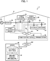
- FIG. 1 is a schematic diagram illustrating an example of an overall configuration of a home system 1 according to an embodiment of the present disclosure.
- the home system 1 includes a power storage apparatus 10 for storing electric power, a power generation apparatus 20 for generating electric power, a breaker 30 for stopping a supply of electric power to a home H, a power measurement device 40 for measuring electric power consumed or generated in the home H, an appliance 50 that consumes electric power in the home H, a power control device 60 for controlling the entire home system 1, and a terminal device 70 for use by a user.
- the bold line in FIG. 1 indicates a power line PL.
- the power storage apparatus 10, the power generation apparatus 20, the breaker 30, and the appliance 50 are connected to the power line PL to receive or provide power via the power line PL.
- Current transformers CT for measuring power flowing through the power line PL are disposed near those devices.
- the dashed lines in FIG. 1 indicate a communication line CL.
- the power storage apparatus 10, the power generation apparatus 20, the power measurement device 40, the appliance 50, the power control device 60, and the terminal device 70 are connected via the communication line CL to a home network N1.
- the communication line CL and the home network N1 may be, for example, a wired or wireless local area network (LAN).
- LAN local area network
- the home system 1 can communicate with a server 80 located outside the home H.
- the server 80 stores an electricity rate table 81 that defines, for example, a rate of electricity (electricity purchase rate) in time periods of the day for a commercial power source PS, that is, commercial power grid.
- the electricity rate table 81 also includes a purchase rate of generated electric power (electricity selling rate). This purchase rate does not need to be uniform, and may be defined in time periods of the day.
- the server 80 further stores weather forecast information 82.
- the weather forecast information 82 may include, for example, forecast weather, a precipitation probability, a forecast temperature, a forecast humidity, and a forecast amount of solar radiation.
- the power control device 60 is communicably connected via an external network N2 to the server 80, and can retrieve the electricity rate table 81 and the weather forecast information 82.
- the power storage apparatus 10 may be, for example, a power storage system including a stationary storage battery (as an example, a lithium-ion battery) and capable of storing (charging) and discharging power.
- the power storage apparatus 10 is controlled via the communication line CL (home network N1) by the power control device 60, and charges and discharges the storage battery.
- the power storage apparatus 10 may be, as another example, a power charge and discharge system using an electric car.
- the power generation apparatus 20 may be, for example, a photovoltaic power generation system including a solar panel for power generation using sunlight and a power conditioner for converting a DC power into an AC power.
- the power generation apparatus 20 is controlled via the communication line CL by the power control device 60, and supplies the generated power to appliances 50 in the home H or causes a reverse power flow of surplus power to the commercial power source PS.
- the power generation apparatus 20 may be a power generation system using wind or a fuel cell.
- the breaker 30 interrupts a supply of power from the commercial power source PS to the power line PL in the home H as appropriate.
- the breaker 30, for example, interrupts an electrical connection between the commercial power source PS and the power line PL when the power supplied from the commercial power source PS to the home H exceeds a rated capacity.
- the capacity of the breaker 30 is determined, for example when a user sets up a contract with an electric power company.
- the breaker 30 may be an earth leakage circuit breaker.
- the breaker 30 may break the connection with the commercial power source PS in case of power outage to achieve a self-sustained operation in the home H.
- the power measurement device 40 detects an amount of power flowing through the power line PL using the current transformer CT described above.
- the power measurement device 40 transmits information of the detected amount of power to the power control device 60. That is, the power measurement device 40 measures, using the current transformer CT, a sold power amount that is a reverse power flow from the power generation apparatus 20 through the power line PL to the commercial power source PS, a purchased power amount that is an inflow from the commercial power source PS to the power line PL, an amount of power generated by the power generation apparatus 20, an amount of power consumed by the appliances 50, an amount of charged power to the power storage apparatus 10, and an amount of discharged power from the power storage apparatus 10 to the power line PL.
- the power measurement device 40 transmits the measurements to the power control device 60, for example, as information of the sold and purchased power amounts, the amount of power generation, the amount of power consumption, and the amounts of charged and discharged power.
- the appliances 50 may be electrical appliances and facility devices, and are power consumed devices that consume power at the home H.
- Examples of the appliances 50 include a heat pump water heater.
- the water heater is also referred to as a heat storage device since it stores electricity as heat.
- FIG. 1 illustrates two appliances 50 located in the home H for ease of description, but the number of appliances 50 can be varied as appropriate in accordance with circumstances.
- the power control device 60 is, for example, a home energy management system (HEMS) controller capable of integrally controlling the appliances 50 in the home H.
- the power control device 60 predicts the amount of power to be generated by the power generation apparatus 20 and an amount of power to be consumed by the appliances 50, and makes an operation plan.
- the operation plan includes a control for the appliances 50 as well as a control for the power storage apparatus 10 to charge and discharge power.
- the power control device 60 controls the power storage apparatus 10 and the appliances 50 in accordance with the operation plan.
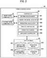
- FIG. 2 is a block diagram illustrating an example of the configuration of the power control device 60.
- the power control device 60 includes an inside-home communicator 61, an outside-home communicator 62, a data storage 63, and a controller 64.
- the inside-home communicator 61 is a communication unit for establishing a connection to the home network N1 through the communication line CL, and communicates, under the control of the controller 64, with the power storage apparatus 10, the power generation apparatus 20, the power measurement device 40, the appliances 50, and the terminal device 70.
- the inside-home communicator 61 for example, receives information of the amount of power sent by the power measurement device 40.
- the inside-home communicator 61 transmits screen data generated by the controller 64, specifically a display controller 644 described later, to the terminal device 70.
- the outside-home communicator 62 is a communication adapter for connection to the external network N2 located outside, and communicates, under the control of the controller 64, with the server 80 located outside.
- the outside-home communicator 62 for example, receives the above-described electricity rate table 81 and weather forecast information 82 from the server 80.
- the data storage 63 may include, for example, non-volatile semiconductor memory, and stores various items of information. Specifically, the data storage 63 stores user setting information 631, management information 632, a prediction model 633, and an operation plan 634.
- the user setting information 631 includes, for example, information of a user schedule and a user preference that are set by a user.
- the user preference is information indicating a course of action referred to when the operation plan is made, and as an example, any preference on economization, energy savings, and comfort is set by the user.
- the management information 632 includes, for example, information received from the server 80, an actual value and a predicted value of the amount of power, and information of the current status of the appliance 50.
- the actual value may be the amount of power generation or the amount of power consumption that is measured by the power measurement device 40.
- the predicted value may be a predicted value of power generation or a predicted value of load that is predicted by the controller 64, specifically a prediction calculator 643 described later.
- the prediction model 633 includes a model for predicting the amount of power to be generated by the power generation apparatus 20 and a model for prediction of the amount of power to be consumed by the appliance 50.
- the prediction model 633 is used by the prediction calculator 643, and the amount of power generation and the amount of power consumption are predicted per unit time, such as every 30 minutes.
- the operation plan 634 is made by the controller 64, specifically an operation planner 645 described later.
- the operation plan 634 includes, for example, details on the energy-saving control for the appliance 50, and details on the power charge and discharge control for the power storage apparatus 10.
- the operation plan 634 is referred to by the controller 64, specifically an appliance controller 646 described later, for control of the appliance 50 and the power storage apparatus 10.
- the controller 64 includes, for example, a central processing unit (CPU), a read only memory (ROM), and a random access memory (RAM), and controls the entire power control device 60.
- the controller 64 includes, as functions thereof, an information acquirer 641, a prediction model updater 642, the prediction calculator 643, the display controller 644, the operation planner 645, and the appliance controller 646. These functions are achieved by use of the RAM by the CPU as working memory to run various programs stored in the ROM as appropriate.
- the information acquirer 641 acquires necessary information.
- the information acquirer 641 also acquires a request for a demand response (DR) or reduction of the amount of power generation that is issued by an aggregator, specifically an electricity retailer through the external network N2.
- the demand response is an incentive system for prompting consumers to reduce or shift their demands, in order to maintain the power demand balance.
- the reduction in the amount of power generation is, for example, a request, issued by the aggregator, for stopping the consumers from selling power when the power supply significantly exceeds the power demand.
- the information acquirer 641 controls the inside-home communicator 61 to acquire, through the home network N1, the amount of power generation and the amount of power consumption from the power measurement device 40, and the user schedule and the user preference from the terminal device 70.
- the information acquirer 641 updates the user setting information 631 and the management information 632 on the basis of the acquired information.
- the prediction model updater 642 updates the prediction model 633 using the predicted values and the actual values.
- the predicted values are the amount of power generation and the amount of power consumption predicted by the prediction calculator 643, and the actual values are the amount of power generation and the amount of power consumption acquired by the information acquirer 641.
- the prediction model updater 642, for example, uses the predicted value per unit time and the actual value corresponding to the predicted value to statistically process an amount of error in the predicted value, and updates the prediction model 633.
- the prediction model updater 642 holds the amount of error in the predicted value as accuracy information for the predicted value per unit time.
- the prediction model updater 642 performs such updating of the prediction model 633 periodically, as an example, once a day.
- the prediction model updater 642 updates the prediction model 633 except for the information of the time period in which the reason has occurred.
- the predetermined reasons may include, for example, an event in which a water heater included in the appliance 50 operates in a time period different from that of the operation plan due to a time shift caused by a user's manual operation, an event of issuance of the demand response (DR request), and an event of issuance of the reduction in the amount of power generation.
- the prediction calculator 643 determines the predicted value using the prediction model 633 updated by the prediction model updater 642.
- the prediction calculator 643 predicts the amount of power to be generated by the power generation apparatus 20 and the amount of power to be consumed by the appliance 50. Specifically, the prediction calculator 643 determines a predicted value per unit time, such as every 30 minutes, and associates the predicted value with the accuracy information.
- the accuracy information is a value represented, in accordance with a relationship between the predicted value per unit time and the actual value, in the form of a dispersion of samples under the same conditions or a hit rate relative to the predicted value. That is, the value being a numerical representation of the relationship between the predicted value and the actual value is used. Thus large dispersion or low hit rate indicates low precision of prediction.
- the prediction calculator 643 may assign a weight to the accuracy in accordance with the weather forecast that differs from the actual value, as an example, the forecast weather or the precipitation probability. Specifically, the prediction calculator 643 assigns a high weight to the accuracy when the condition that the weather is forecast to be clear has a high predictability, or conversely, assigns a low weight to the accuracy when the condition that the weather is forecast to be cloudy has a low predictability. Additionally or alternatively, the prediction calculator 643 may assign a weight to the accuracy on the basis of time, number of elapsed years, and facility condition.
- the prediction calculator 643 may assign a weight to the accuracy in accordance with a proportion of anomalous values in the actual values. Specifically, the prediction calculator 643 assigns a low weight to the accuracy when the proportion of anomalous values is large.
- the prediction calculator 643 may compare the predicted value with the actual value, and reflect the comparison on the accuracy information in accordance with a misprediction degree. When a plurality of predicted values is used, the prediction calculator 643 may provide new accuracy information using accuracy information of each predicted value.
- the prediction calculator 643 performs such prediction calculation, for example at a timing of acquisition of the new weather forecast information 82 from the server 80 or a periodic operation-planning timing.
- the prediction calculator 643 calculates the predicted value of power generation and the predicted value of load with accuracy information associated with the determined predicted values, and then updates management information 632 with the predicted values.
- the display controller 644 generates screen data to be provided on the terminal device 70. Specifically, the display controller 644 generates the screen data including a power generation amount prediction screen P1 as illustrated in FIG. 3A and a power consumption amount prediction screen P2 as illustrated in FIG. 3B .
- FIG. 3A which is the power generation amount prediction screen P1 is a graph showing the predicted value of power generation as a function of time.
- a degree of variance indicates the accuracy of the predicted value.
- a time period with a narrower range of variance indicates that the predicted value in the time period has a higher accuracy, that is, the reliability of the predicted value is high
- a time period with a wider range of variance indicates that the predicted value in the time period has a lower accuracy, that is the reliability of the predicted value is low.
- the display controller 644 generates the power generation amount prediction screen P1 on the basis of the predicted value per unit time and the accuracy information for the amount of power generation determined by the prediction calculator 643 as described above.
- the power consumption amount prediction screen P2 as illustrated in FIG. 3B provides a graph showing the predicted value of load (amount of power consumption) as a function of time. In this graph, the range of variance also indicates the accuracy of the predicted value.
- the display controller 644 generates the power consumption amount prediction screen P2 on the basis of the predicted value per unit time and the accuracy information for the amount of power consumption determined by the prediction calculator 643 as described above.
- the screens P1 and P2 are only examples, and other screens may be used.
- the display controller 644 may, for example, generate a power generation amount prediction screen P3 as illustrated in FIG. 4A and a power consumption amount prediction screen P4 as illustrated in FIG. 4B .
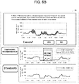
- the power generation amount prediction screen P3 as illustrated in FIG. 4A provides graphs separately showing the predicted value of power generation and the prediction accuracy. Specifically, the predicted value of power generation is presented as a bar graph on a time-period basis, while the prediction accuracy is presented as the graph plotted over time.
- the power consumption amount prediction screen P4 as illustrated in FIG. 4B provides graphs separately showing the predicted value of load (amount of power consumption) and the prediction accuracy. Specifically, the predicted value of load is presented as a graph on a time-period basis, while the prediction accuracy is presented as a graph plotted over time.
- the operation planner 645 makes the operation plan using the predicted values determined by the prediction calculator 643, the user schedule included in the user setting information 631, and the electricity rate table 81 and the weather forecast information 82 received from the server 80.
- the operation planner 645 makes the operation plan only with other information without using the predicted value.
- the operation planner 645 may make the operation plan with a tolerance to the predicted value set higher than the tolerance set when the accuracy of the predicted value is high.
- the operation planner 645 stores the operation plan made as described above in the data storage 63.
- the appliance controller 646 controls the power storage apparatus 10 and the appliance 50 in accordance with the operation plan made by the operation planner 645, that is, the operation plan 634 in the data storage 63.
- the appliance controller 646 periodically acquires the state of appliance 50 by automatic control not based on the operation plan 634, and stores the information of the state by adding to or writing over the management information 632.
- the terminal device 70 which is, for example, a portable terminal, such as a tablet terminal or a smartphone, is used by a user.
- the terminal device 70 displays a screen, for example the power generation amount prediction screen P1 and the power consumption amount prediction screen P2 as described above, on the basis of the screen data transmitted by the power control device 60.
- the terminal device 70 accepts a user's manual operation, and transmits details of the operation to the power control device 60.
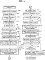
- FIG. 5 is a flowchart illustrating an example of an operation planning process performed by the controller 64.
- the operation planning process starts, for example, periodically or upon request from the user operating the terminal device 70.
- the controller 64 acquires the user preference (step S101). Specifically, the information acquirer 641 acquires from the terminal device 70 the user preference indicating a course of action used for making the operation plan. More specifically, the information acquirer 641 acquires the user preference on any of economization, energy savings, or comfort. Without any additional user request, the information acquirer 641 acquires the previously set user preference from the management information 632.
- the controller 64 changes a parameter (step S102).
- the controller 64 for example, changes a parameter for optimization of power source selection in accordance with the acquired user preference.
- the controller 64 acquires the electricity rate table 81 (step S103). Specifically, the information acquirer 641 controls the outside-home communicator 62 to acquire the electricity rate table 81 via the external network N2 from the server 80. The information acquirer 641 may access the server 80 to confirm whether the electricity rate table 81 is updated, and if not updated, may acquire the previously acquired electricity rate table from the management information 632.
- the controller 64 predicts an amount of power generation (step S104). Specifically, the prediction calculator 643 predicts the amount of power to be generated by the power generation apparatus 20. More specifically, the prediction calculator 643 determines a predicted value per unit time, such as every 30 minutes, and associates the predicted value with accuracy information.
- the controller 64 predicts a load (step S105). Specifically, the prediction calculator 643 predicts an amount of power to be consumed by the appliance 50. In this case, the prediction calculator 643 determines a predicted value per unit time, such as every 30 minutes, and associates the predicted value with the accuracy information.
- the controller 64 may then generate screen data for the predicted values predicted in steps S104 and S105, and cause display of the screen data on the terminal device 70.
- the display controller 644 causes display on the terminal device 70 of the above-described power generation amount prediction screen P1 as illustrated in FIG. 3A and the above-described power consumption amount prediction screen P2 as illustrated in FIG. 3B .
- the degree of variance on each of the screens P1 and P2 indicates the accuracy of the predicted value. Specifically, a time period with a narrower range of variance indicates that the predicted value in the time period has a higher accuracy, while a time period with a wider range of variance indicates that the predicted value in the time period has a lower accuracy. The user thus can easily know the reliability of the predicted value of the amount of power generation and the predicted value of the amount of power consumption.
- the controller 64 determines whether the prediction accuracy is lower than the reference A (step S106).
- the reference A is a predetermined value that is a lower limit for keeping the minimum reliability of the predicted value. That is, the controller 64 determines, on the basis of the accuracy information associated with the predicted value, whether the predicted value falls below the minimum reliability.
- the controller 64 determines whether the prediction accuracy is equal to or higher than the reference A (No in step S106).
- the controller 64 determines whether the prediction accuracy is less than the reference B (step S107).
- the reference B is a predetermined value that is a lower limit for keeping the sufficient reliability of the predicted value. That is, the controller 64 determines whether the predicted value falls below the lower limit for keeping the sufficient reliability.
- step S107 When the controller 64 determines that the prediction accuracy is equal to or higher than the reference B (No in step S107), the processing proceeds to step S109 described later.
- step S108 the controller 64 corrects the predicted value (step S108). Specifically, the controller 64 corrects the predicted value to reduce a possible loss caused by a wrong prediction in consideration of the possibility that the prediction is wrong since the accuracy of the predicted value does not exceed the reference for keeping the sufficient reliability. The controller 64, for example, corrects the predicted value to be lower so as to reduce the amount of electricity to be purchased to cover the shortage of electrical energy.
- the controller 64 makes a heat storage control plan 1 (step S109).
- the operation planner 645 makes an operation plan for a water heater included in the appliance 50, that is, a heat storage device, using the electricity rate table 81 received from the server 80.
- the operation planner 645 makes the operation plan for achieving a time shift for the water heater to heat up water during the daytime.
- the water heater is typically operated late at night, but if the electricity rate table 81 includes a time period with low electricity rate even in the daytime, the operation of the water heater is time-shifted to the time period. In this time-shifting, the operation planner 645 shifts the water heating operation of the water heater, for example provided that the power consumption in the time period to which the operation is shifted does not exceed a peak-cut level.
- the controller 64 makes a heat storage control plan 2 (step S110). Specifically, the operation planner 645 makes an operation plan for the heat storage device to reduce the amount of power generation using the generated power that is estimated to be surplus. For example, when there is a time period in which a surplus of the generated power exceeds the power consumption of the water heater, the operation planner 645, for example, shifts the water heating operation of the water heater to the time period. Specifically, the operation planner 645 shifts the water heating operation of the water heater, provided that the amount of power consumption in the time period to which the operation is shifted does not exceed a predicted amount of power generation.
- step S106 determines in step S106 that the prediction accuracy is lower than the reference A (Yes in step S106), the controller 64 does not shift the water heating operation of the water heater (step S111).
- the controller 64 re-predicts the load (step S112). Specifically, the prediction calculator 643 predicts the amount of power to be consumed by the appliance 50, in accordance with the heat storage control plans 1 and 2 made in steps S109 and S110 as described above. In this case, the prediction calculator 643 also determines a predicted value per unit time, such as every 30 minutes, and associates the predicted value with the accuracy information. The controller 64 may then generate screen data for the re-predicted value, and display the screen data on the terminal device 70.
- the controller 64 determines whether the prediction accuracy is lower than the reference A' (step S113).
- the reference A' is a predetermined value that is a lower limit for keeping the minimum reliability of the predicted value, for example, a limit that is more relaxed than the reference A described above.
- the reference A may be used instead of the reference A'.
- the controller 64 determines whether the prediction accuracy is less than the reference B' (step S114).
- the reference B' is a predetermined value that is a lower limit for keeping the sufficient reliability of the predicted value, for example, a limit that is relaxed more than the reference B described above.
- the reference B may be used instead of the reference B'.
- step S114 determines that the prediction accuracy is equal to or higher than the reference B' (No in step S114).
- the processing proceeds to step S116 described later.
- the controller 64 determines that the prediction accuracy is lower than the reference B' (Yes in step S114)
- the controller 64 corrects the predicted value (step S115).
- the controller 64 makes a power saving control plan 1 (step S116).
- the operation planner 645 makes a time-period based operation plan for energy savings so that the electricity bill cost is within a target.
- the controller 64 makes a power saving control plan 2 (step S117).
- the operation planner 645 makes a time-period based operation plan for power savings in response to the demand response, that is, the DR request.
- the controller 64 re-predicts the load (step S118). Specifically, the prediction calculator 643 predicts the amount of power to be consumed by the appliance 50, in accordance with the power saving control plans 1 and 2 made in steps S116 and S117 as described above. In this case, the prediction calculator 643 also determines a predicted value per unit time, such as every 30 minutes, and associates the predicted value with the accuracy information. The controller 64 may then generate screen data for the re-predicted value, and may cause display of the screen data on the terminal device 70.
- the controller 64 determines whether the prediction accuracy is lower than the reference A" (step S119).
- the reference A" is a predetermined value that is a lower limit for keeping the minimum reliability of the predicted value, for example, a limit that is more relaxed than the reference A described above.
- the reference A may be used instead of the reference A".
- the controller 64 determines whether the prediction accuracy is less than the reference B" (step S120).
- the reference B" is a predetermined value that is a lower limit for keeping the sufficient reliability of the predicted value, for example, a limit that is relaxed more than the reference B described above.
- the reference B may be used instead of the reference B".
- step S120 When the controller 64 determines that the prediction accuracy is equal to or higher than the reference B" (No in step S120), the processing proceeds to step S122 described later. Conversely, when the controller 64 determines that the prediction accuracy is lower than the reference B" (Yes in step S120), the controller 64 corrects the predicted value (step S121).
- the controller 64 optimizes selection of power sources (step S122).
- the controller 64 for example, optimizes a charge and discharge control of the power storage apparatus 10.
- step S119 When the controller 64 determines in step S119 described above that the prediction accuracy is lower than the reference A" (Yes in step S119), the controller 64 notifies the power storage apparatus 10 that there is no change in the charge and discharge control (step S123).
- This operation planning process enables a proper operation plan to be made using the accuracy of the predicted value.
- the power storage and the heat storage are achieved only by the surplus power of the generated power to reduce the amount of power generation, that is, the charge control of the power storage apparatus 10 and the water heater included in the appliance 50 are operated only by the surplus power.
- the amount of power generated by the power generation apparatus 20 varies greatly depending on the weather, which may cause a great difference between the actual value and the predicted value.
- an appliance 50 incapable of easy change of the capability thereof, such as a heat pump water heater is operated on the basis of the predicted value, the amount of power consumption may exceed the surplus power, thereby causing purchase of electricity.
- present disclosure makes the operation plan without the use of the predicted value with the low accuracy or with the use of the predicted value corrected in accordance with the accuracy, which enables prior avoidance of the occurrence of the purchase of electricity.
- the prediction calculator 643 statistically processes a relationship between the predicted value and the actual value, and applies the result to the predicted value as accuracy information. This enables the operation planner 645 to know the reliability of the predicted value and make the operation plan using the reliability of the predicted value. Thus even when a misprediction occurs, the adverse effects that may be caused can be reduced while the appliance 50 keeps the user-preference based operation.
- Improvement in the prediction precision involves increasing functionality of the prediction model 633, which typically raises concerns regarding an increase in the processing load or the required amount of memory in the power control device 60.
- the present disclosure does not need to increase the processing load or the required amount of memory because associating the accuracy information, or an index that indicates reliability, with the predicted value enables the power control device 60 to use the predicted value in various ways in accordance with the accuracy.
- the power control device 60 can thus achieve functions even at relatively low cost.
- the above embodiment describes an example in which the power control device 60 makes an operation plan and uses the operation plan.
- multiple operation plans may be suggested to a user so that the user can select one of the operation plans.
- the power generation amount prediction screen P1 as illustrated in FIG. 3A and the power consumption amount prediction screen P2 illustrated in FIG. 3B may be presented to the user together with the operation plans. The user having recognized the reliability of prediction can then easily select one of the operation plans.
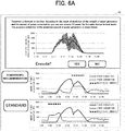
- the display controller 644 may generate an operation plan selection screen P5 as illustrated in FIG. 6A and an operation plan selection screen P6 as illustrated in FIG. 6B , and may cause display of the screen data on the terminal device 70.
- the operation plan selection screens P5 and P6 help make the user recognize the reliability of the prediction, which leads to the user's easy selection of the operation plan.
- the power control device 60 may be provided with a display, and may cause the various screens to be displayed on the display.
- the above embodiment describes the home system 1 by way of example. However, in some embodiments, the present disclosure can be similarly applied to, for example, a building system installed in a building.
- the above embodiment describes an example in which the power control device 60 is installed in the house H.
- the power control device 60 may be installed outside the home H.
- the server 80 illustrated in FIG. 1 may function as the power control device 60. In this case, the cost of consumed power can be properly visualized and displayed.
- an operation program defining the operation of the power control device 60 may be applied to an existing personal computer or an information terminal device, thereby enabling such a personal computer to function as the power control device 60 according to the present disclosure.
- any distribution method of such a program can be selected, and the program may be distributed in a form of a computer-readable recording medium storing the program, such as a compact disc read-only memory (CD-ROM), a digital versatile disc (DVD), a magneto optical disc (MO), a memory card, and the like, or via a communication network, such as the Internet.
- a computer-readable recording medium storing the program, such as a compact disc read-only memory (CD-ROM), a digital versatile disc (DVD), a magneto optical disc (MO), a memory card, and the like
- CD-ROM compact disc read-only memory
- DVD digital versatile disc
- MO magneto optical disc
- the present disclosure can be applied to a power control device, an operation planning method, and a program that can achieve proper use of a predicted value of power.
Landscapes
- Engineering & Computer Science (AREA)
- Power Engineering (AREA)
- Environmental & Geological Engineering (AREA)
- Life Sciences & Earth Sciences (AREA)
- Atmospheric Sciences (AREA)
- Biodiversity & Conservation Biology (AREA)
- Ecology (AREA)
- Environmental Sciences (AREA)
- Supply And Distribution Of Alternating Current (AREA)
- Management, Administration, Business Operations System, And Electronic Commerce (AREA)
- Remote Monitoring And Control Of Power-Distribution Networks (AREA)
Applications Claiming Priority (1)
| Application Number | Priority Date | Filing Date | Title |
|---|---|---|---|
| PCT/JP2015/084661 WO2017098631A1 (fr) | 2015-12-10 | 2015-12-10 | Dispositif régulateur d'énergie, procédé d'élaboration de plans d'exploitation, et programme |
Publications (2)
| Publication Number | Publication Date |
|---|---|
| EP3389162A1 true EP3389162A1 (fr) | 2018-10-17 |
| EP3389162A4 EP3389162A4 (fr) | 2018-12-05 |
Family
ID=59013996
Family Applications (1)
| Application Number | Title | Priority Date | Filing Date |
|---|---|---|---|
| EP15910247.4A Withdrawn EP3389162A4 (fr) | 2015-12-10 | 2015-12-10 | Dispositif régulateur d'énergie, procédé d'élaboration de plans d'exploitation, et programme |
Country Status (6)
| Country | Link |
|---|---|
| US (1) | US11271400B2 (fr) |
| EP (1) | EP3389162A4 (fr) |
| JP (1) | JP6598876B2 (fr) |
| CN (1) | CN108292860B (fr) |
| BR (1) | BR112018008377A2 (fr) |
| WO (1) | WO2017098631A1 (fr) |
Families Citing this family (26)
| Publication number | Priority date | Publication date | Assignee | Title |
|---|---|---|---|---|
| US10444719B2 (en) * | 2016-07-29 | 2019-10-15 | Panasonic Intellectual Property Management Co., Ltd. | Energy management device and energy management method |
| JP6950296B2 (ja) * | 2017-06-22 | 2021-10-13 | 住友電気工業株式会社 | 制御計画作成装置、制御計画作成方法およびコンピュータプログラム |
| JPWO2019082426A1 (ja) * | 2017-10-23 | 2020-11-12 | 住友電気工業株式会社 | エネルギー管理装置、エネルギー管理システム、及び、エネルギー管理方法 |
| US10734811B2 (en) * | 2017-11-27 | 2020-08-04 | Ihi Inc. | System and method for optimal control of energy storage system |
| JP6728323B2 (ja) * | 2018-03-12 | 2020-07-22 | 株式会社E.I.エンジニアリング | 運転支援システム、運転支援方法、これを実行させるためのコンピュータプログラム及びこのプログラムを記録した記録媒体 |
| WO2019187372A1 (fr) * | 2018-03-30 | 2019-10-03 | Necソリューションイノベータ株式会社 | Système de prédiction, ainsi que système, procédé et programme de génération de modèle |
| SE543908C2 (en) * | 2018-07-04 | 2021-09-21 | Epiroc Rock Drills Ab | Method and arrangement for managing power consumption in a mine |
| JP7143148B2 (ja) * | 2018-08-23 | 2022-09-28 | 三菱重工業株式会社 | 予測装置、予測方法、及びプログラム |
| JP7203551B2 (ja) * | 2018-09-28 | 2023-01-13 | 大和ハウス工業株式会社 | 電力供給システム |
| JP7216566B2 (ja) * | 2019-02-19 | 2023-02-01 | 日立造船株式会社 | 情報処理装置、情報処理方法、および情報処理プログラム |
| EP3937346A4 (fr) | 2019-03-04 | 2022-05-04 | Asahi Kasei Kabushiki Kaisha | Dispositif de planification, dispositif de commande, procédé et programme |
| WO2020195525A1 (fr) * | 2019-03-22 | 2020-10-01 | 株式会社カネカ | Système de commande de puissance et procédé de commande de puissance |
| EP3739710B1 (fr) * | 2019-05-13 | 2022-06-29 | Siemens Schweiz AG | Commande de systèmes photovoltaïques |
| DE102019212773A1 (de) * | 2019-08-26 | 2021-03-04 | Technische Hochschule Lübeck | Verfahren zur Stabilisierung eines elektrischen Energienetzes |
| JP7267149B2 (ja) * | 2019-08-26 | 2023-05-01 | 三菱電機株式会社 | 制御装置、給湯システム、給湯機制御方法およびプログラム |
| FR3105516B1 (fr) * | 2019-12-20 | 2021-12-17 | Sagemcom Energy & Telecom Sas | Procédé de délestage de sorties d’une installation de production d’énergie électrique |
| JP2021100326A (ja) * | 2019-12-20 | 2021-07-01 | パナソニックIpマネジメント株式会社 | 電力制御ユニット、及び分電盤システム |
| KR102384980B1 (ko) * | 2020-05-15 | 2022-04-08 | 한국지역난방공사 | 신재생 열병합발전소를 활용한 가상발전소 시스템 및 이를 이용한 가상발전소 운영 방법 |
| US12047029B2 (en) * | 2020-09-10 | 2024-07-23 | Eric Robert ANDERSON | Electricity generation system and method |
| JP7671486B2 (ja) * | 2020-12-28 | 2025-05-02 | 国立大学法人東京科学大学 | 系統協調/分散型エネルギーシステム |
| JP2023008053A (ja) * | 2021-07-05 | 2023-01-19 | 三菱電機株式会社 | エネルギーマネジメントシステム、機器制御サーバ、エネルギーマネジメント方法、及び、プログラム |
| JP2023107061A (ja) * | 2022-01-21 | 2023-08-02 | 株式会社エナリス | 電力協調制御システム、電力協調制御方法及び電力協調制御プログラム |
| JP7824837B2 (ja) * | 2022-07-01 | 2026-03-05 | 株式会社東芝 | 情報処理装置、情報処理方法、コンピュータプログラム及び情報処理システム |
| US20240177068A1 (en) * | 2022-11-29 | 2024-05-30 | Fmr Llc | Predicting user attributes using uncertainty estimate modeling |
| FR3142446A1 (fr) * | 2022-11-30 | 2024-05-31 | Psa Automobiles Sa | Procede de reutilisation de composants d’un systeme de chaine de traction de vehicule electrique dans un systeme d’alimentation electrique autonome non automobile |
| JP2025003189A (ja) * | 2023-06-23 | 2025-01-09 | 株式会社日立製作所 | 電力需給管理装置および電力需給管理方法 |
Family Cites Families (25)
| Publication number | Priority date | Publication date | Assignee | Title |
|---|---|---|---|---|
| JP3994910B2 (ja) * | 2003-05-08 | 2007-10-24 | 株式会社日立製作所 | 電力売買支援システム |
| JP3966236B2 (ja) | 2003-06-19 | 2007-08-29 | 株式会社日立製作所 | 発電設備の運転計画方法及び発電設備の運転計画システム |
| US7860555B2 (en) * | 2005-02-02 | 2010-12-28 | Voyage Medical, Inc. | Tissue visualization and manipulation system |
| JP4245583B2 (ja) | 2005-04-15 | 2009-03-25 | 日本電信電話株式会社 | 分散型エネルギーシステムの制御装置、制御方法、プログラム、および記録媒体 |
| JP4808754B2 (ja) | 2008-08-28 | 2011-11-02 | 三菱電機株式会社 | 自然エネルギー発電制御システム |
| JP5294980B2 (ja) * | 2009-05-20 | 2013-09-18 | 株式会社日立製作所 | プラント運転データ予測システム及び方法 |
| JP5659486B2 (ja) | 2009-12-17 | 2015-01-28 | 富士電機株式会社 | 発電計画作成方法および発電計画作成システム |
| JP2011259656A (ja) | 2010-06-11 | 2011-12-22 | Mitsubishi Heavy Industries Mechatronics Systems Ltd | エネルギー管理装置、エネルギー管理方法、及びエネルギー管理プログラム |
| US8392031B2 (en) * | 2011-02-28 | 2013-03-05 | General Electric Company | System and method for load forecasting |
| US9081374B2 (en) * | 2011-03-10 | 2015-07-14 | Deteotent Inc. | Calibrating algorithms for determining electrical load and lifestyle characteristics |
| JP5740215B2 (ja) * | 2011-06-10 | 2015-06-24 | クラリオン株式会社 | エネルギー消費量計算装置とそのエネルギー消費量計算方法 |
| JP2013012080A (ja) | 2011-06-29 | 2013-01-17 | Sharp Corp | 予測方法及び予測システム |
| US9136706B2 (en) * | 2011-12-28 | 2015-09-15 | Kabushiki Kaisha Toshiba | Power management system and power management method |
| JP5842654B2 (ja) * | 2012-02-14 | 2016-01-13 | オムロン株式会社 | システム制御装置およびシステム制御方法 |
| WO2013136419A1 (fr) | 2012-03-12 | 2013-09-19 | 富士通株式会社 | Procédé pour la création d'un plan de fonctionnement, programme de création d'un plan de fonctionnement et dispositif de création d'un plan de fonctionnement |
| JP5957372B2 (ja) | 2012-11-14 | 2016-07-27 | 株式会社日立製作所 | 日射量計算方法及び供給電力決定方法 |
| US10338622B2 (en) * | 2013-06-27 | 2019-07-02 | Panasonic Corporation | Power adjustment device, power adjustment method, power adjustment system, power storage device, server, program |
| JP6180826B2 (ja) * | 2013-07-02 | 2017-08-16 | 株式会社東芝 | エネルギー管理サーバ、エネルギー管理方法およびプログラム |
| JP6179237B2 (ja) | 2013-07-22 | 2017-08-16 | 富士通株式会社 | 電力消費量予測システム、方法、及びプログラム |
| US9846886B2 (en) * | 2013-11-07 | 2017-12-19 | Palo Alto Research Center Incorporated | Strategic modeling for economic optimization of grid-tied energy assets |
| JP2015162925A (ja) * | 2014-02-26 | 2015-09-07 | 株式会社Nttファシリティーズ | 電力管理システム |
| CN103778486A (zh) * | 2014-02-28 | 2014-05-07 | 国家电网公司 | 一种配电网负荷预测方法 |
| JP6404650B2 (ja) * | 2014-09-11 | 2018-10-10 | 株式会社東芝 | 機器運転設定値決定装置、機器運転設定値決定方法、及び、機器運転設定値決定プログラム |
| JP6414743B2 (ja) * | 2014-11-28 | 2018-10-31 | 富士通株式会社 | 電源制御装置、電源制御プログラム、電源制御方法及び電源制御システム |
| KR101529678B1 (ko) * | 2014-12-31 | 2015-06-19 | 연세대학교 산학협력단 | 태양광 발전량을 극대화할 수 있는 복합식 태양광 추미 방법, 이를 이용한 태양광 추미 장치 및 태양광 발전 블라인드 시스템 |
-
2015
- 2015-12-10 CN CN201580084842.2A patent/CN108292860B/zh not_active Expired - Fee Related
- 2015-12-10 WO PCT/JP2015/084661 patent/WO2017098631A1/fr not_active Ceased
- 2015-12-10 JP JP2017554736A patent/JP6598876B2/ja active Active
- 2015-12-10 BR BR112018008377-1A patent/BR112018008377A2/pt not_active Application Discontinuation
- 2015-12-10 EP EP15910247.4A patent/EP3389162A4/fr not_active Withdrawn
- 2015-12-10 US US15/759,245 patent/US11271400B2/en active Active
Also Published As
| Publication number | Publication date |
|---|---|
| WO2017098631A1 (fr) | 2017-06-15 |
| EP3389162A4 (fr) | 2018-12-05 |
| CN108292860A (zh) | 2018-07-17 |
| US11271400B2 (en) | 2022-03-08 |
| BR112018008377A2 (pt) | 2018-10-23 |
| JPWO2017098631A1 (ja) | 2018-03-22 |
| JP6598876B2 (ja) | 2019-10-30 |
| US20180262003A1 (en) | 2018-09-13 |
| CN108292860B (zh) | 2022-04-08 |
Similar Documents
| Publication | Publication Date | Title |
|---|---|---|
| US11271400B2 (en) | Power control device, operation plan planning method, and recording medium | |
| US10298056B2 (en) | Power control system, power control method, and recording medium | |
| JP5095495B2 (ja) | 電力システムおよびその制御方法 | |
| US11164111B2 (en) | Electric power management system for reducing large and rapid change in power received from electricity delivery system | |
| JP6249895B2 (ja) | 電力制御システム、方法及び電力制御装置 | |
| JP6069738B2 (ja) | 充放電制御システム、充放電制御方法、および充放電制御プログラム | |
| KR101522858B1 (ko) | 건물의 최대 수요전력 제어 기능을 갖는 에너지관리시스템 및 그 제어방법 | |
| US11342751B2 (en) | Power management system for customer connected to power network and having load apparatus and power storage apparatus | |
| JP6403875B2 (ja) | 機器管理装置、機器管理システム、機器管理方法及びプログラム | |
| WO2016088761A1 (fr) | Système de commande d'énergie électrique, procédé de commande d'énergie électrique, et programme | |
| JP2016015846A (ja) | 電力システム、御装置及び充放電制御方法 | |
| US9851734B2 (en) | Alert presentation apparatus and alert presentation method | |
| CN104285353B (zh) | 能量管理设备、能量管理方法 | |
| JP5143209B2 (ja) | 中水利用管理システム | |
| JP6664479B2 (ja) | 制御装置、電力管理システム、充放電の制御方法及びプログラム | |
| WO2016031065A1 (fr) | Dispositif d'estimation de consommation de puissance, système de gestion d'appareils, procédé d'estimation de consommation de puissance, et programme | |
| JP2022066217A (ja) | 給湯方法、及び、制御装置 | |
| JP5969365B2 (ja) | 電力制御システム | |
| JP6543187B2 (ja) | 蓄電池制御方法 | |
| JP2016046916A (ja) | 需給管理システム | |
| KR20170123008A (ko) | 전기 디바이스의 소비 전력 제어 장치 | |
| US9929564B2 (en) | Utility provisioning in an energy resource system |
Legal Events
| Date | Code | Title | Description |
|---|---|---|---|
| PUAI | Public reference made under article 153(3) epc to a published international application that has entered the european phase |
Free format text: ORIGINAL CODE: 0009012 |
|
| 17P | Request for examination filed |
Effective date: 20180327 |
|
| AK | Designated contracting states |
Kind code of ref document: A1 Designated state(s): AL AT BE BG CH CY CZ DE DK EE ES FI FR GB GR HR HU IE IS IT LI LT LU LV MC MK MT NL NO PL PT RO RS SE SI SK SM TR |
|
| AX | Request for extension of the european patent |
Extension state: BA ME |
|
| A4 | Supplementary search report drawn up and despatched |
Effective date: 20181106 |
|
| RIC1 | Information provided on ipc code assigned before grant |
Ipc: H02J 3/38 20060101ALI20181030BHEP Ipc: H02J 3/00 20060101ALI20181030BHEP Ipc: H02J 13/00 20060101AFI20181030BHEP Ipc: H02S 50/10 20140101ALI20181030BHEP Ipc: H02S 50/00 20140101ALI20181030BHEP Ipc: H02J 3/14 20060101ALI20181030BHEP |
|
| DAV | Request for validation of the european patent (deleted) | ||
| DAX | Request for extension of the european patent (deleted) | ||
| 17Q | First examination report despatched |
Effective date: 20200305 |
|
| STAA | Information on the status of an ep patent application or granted ep patent |
Free format text: STATUS: THE APPLICATION HAS BEEN WITHDRAWN |
|
| 18W | Application withdrawn |
Effective date: 20210217 |