EP3389178A1 - Dispositif convertisseur de courant pour une machine électrique, véhicule automobile et procédé de fonctionnement d'un dispositif convertisseur de courant - Google Patents
Dispositif convertisseur de courant pour une machine électrique, véhicule automobile et procédé de fonctionnement d'un dispositif convertisseur de courant Download PDFInfo
- Publication number
- EP3389178A1 EP3389178A1 EP18163260.5A EP18163260A EP3389178A1 EP 3389178 A1 EP3389178 A1 EP 3389178A1 EP 18163260 A EP18163260 A EP 18163260A EP 3389178 A1 EP3389178 A1 EP 3389178A1
- Authority
- EP
- European Patent Office
- Prior art keywords
- measuring means
- switching
- current
- control device
- phase
- Prior art date
- Legal status (The legal status is an assumption and is not a legal conclusion. Google has not performed a legal analysis and makes no representation as to the accuracy of the status listed.)
- Granted
Links
Images

Classifications
-
- H—ELECTRICITY
- H02—GENERATION; CONVERSION OR DISTRIBUTION OF ELECTRIC POWER
- H02M—APPARATUS FOR CONVERSION BETWEEN AC AND AC, BETWEEN AC AND DC, OR BETWEEN DC AND DC, AND FOR USE WITH MAINS OR SIMILAR POWER SUPPLY SYSTEMS; CONVERSION OF DC OR AC INPUT POWER INTO SURGE OUTPUT POWER; CONTROL OR REGULATION THEREOF
- H02M1/00—Details of apparatus for conversion
- H02M1/32—Means for protecting converters other than automatic disconnection
-
- H—ELECTRICITY
- H02—GENERATION; CONVERSION OR DISTRIBUTION OF ELECTRIC POWER
- H02K—DYNAMO-ELECTRIC MACHINES
- H02K11/00—Structural association of dynamo-electric machines with electric components or with devices for shielding, monitoring or protection
- H02K11/30—Structural association with control circuits or drive circuits
- H02K11/33—Drive circuits, e.g. power electronics
-
- H—ELECTRICITY
- H02—GENERATION; CONVERSION OR DISTRIBUTION OF ELECTRIC POWER
- H02P—CONTROL OR REGULATION OF ELECTRIC MOTORS, ELECTRIC GENERATORS OR DYNAMO-ELECTRIC CONVERTERS; CONTROLLING TRANSFORMERS, REACTORS OR CHOKE COILS
- H02P29/00—Arrangements for regulating or controlling electric motors, appropriate for both AC and DC motors
- H02P29/60—Controlling or determining the temperature of the motor or of the drive
- H02P29/68—Controlling or determining the temperature of the motor or of the drive based on the temperature of a drive component or a semiconductor component
-
- H—ELECTRICITY
- H02—GENERATION; CONVERSION OR DISTRIBUTION OF ELECTRIC POWER
- H02K—DYNAMO-ELECTRIC MACHINES
- H02K11/00—Structural association of dynamo-electric machines with electric components or with devices for shielding, monitoring or protection
- H02K11/20—Structural association of dynamo-electric machines with electric components or with devices for shielding, monitoring or protection for measuring, monitoring, testing, protecting or switching
- H02K11/25—Devices for sensing temperature, or actuated thereby
-
- H—ELECTRICITY
- H02—GENERATION; CONVERSION OR DISTRIBUTION OF ELECTRIC POWER
- H02K—DYNAMO-ELECTRIC MACHINES
- H02K11/00—Structural association of dynamo-electric machines with electric components or with devices for shielding, monitoring or protection
- H02K11/20—Structural association of dynamo-electric machines with electric components or with devices for shielding, monitoring or protection for measuring, monitoring, testing, protecting or switching
- H02K11/27—Devices for sensing current, or actuated thereby
-
- H—ELECTRICITY
- H02—GENERATION; CONVERSION OR DISTRIBUTION OF ELECTRIC POWER
- H02P—CONTROL OR REGULATION OF ELECTRIC MOTORS, ELECTRIC GENERATORS OR DYNAMO-ELECTRIC CONVERTERS; CONTROLLING TRANSFORMERS, REACTORS OR CHOKE COILS
- H02P29/00—Arrangements for regulating or controlling electric motors, appropriate for both AC and DC motors
- H02P29/02—Providing protection against overload without automatic interruption of supply
- H02P29/024—Detecting a fault condition, e.g. short circuit, locked rotor, open circuit or loss of load
- H02P29/0241—Detecting a fault condition, e.g. short circuit, locked rotor, open circuit or loss of load the fault being an overvoltage
Definitions
- ISO 26262 defines ASIL D as the accuracy of determining the torque electrical machine, which can be met by a redundant determination of the currents flowing along the phase conductors.
- the invention is based on the idea that, instead of an additional current measuring means for the second phase conductor, at least one second measured value of the short circuit detection device, which is assigned to a switching element, be used for the redundant determination of the current strengths and thus the calculated value formed from the first measured values can be determined on the basis of the second measured value or values plausibility. Since such short circuit detection devices are typically provided for detecting bridge and / or winding short circuits in a power converter device, the at least one second measured value can advantageously be obtained without the provision of additional components.
- the second measured values of the short-circuit detection devices per se, the accuracy requirements for controlling the torque and / or the rotational speed of the electrical machine according to the current state of the art do not meet, but provide sufficient accuracy for the plausibility of the currents along the phase conductors.
- the control device is preferably also designed to determine a boost drift of a current measuring device for plausibility checking.
- a gain drift is to be understood as meaning the proportional deviation of the first measured value from the actual current along the first phase conductor resulting in the event of a fault of the current measuring means. Occurs during the operation of the power converter device such a gain drift, there is a faulty first measured value, which also affects the calculated value. However, this error does not relate to the second measured value of the short circuit detection device, so that the gain drift can be detected on the basis of a lack of plausibility of the calculated value and / or a first measured value with respect to at least one second measured value. An assignment of first and second measured values can be stored in a memory unit of the control device.
- control device is further designed to determine a plausibility deviation of the calculated value of a second measured value with respect to a switching element which generates the current along the second phase line.
- second measured values can be registered with plausible calculated values in a fault-free operating case of the first current measuring means, wherein a deviation of the calculated value from a second measured value can be determined. It is also possible here for an assignment of calculation values to second measured values to be stored in the or a memory unit of the control device.
- a temperature determining device that detects and / or models at least one temperature may be provided, wherein the control device is further designed to take account of the temperature during the plausibility check, in particular to correct the second measured value or values ,
- This measure is based on the knowledge that the second measured values detected with respect to the switching elements are dependent on the temperature of the switching element. For transistors as switching elements, this is, for example, the junction temperature.
- the temperature detection device preferably has a temperature sensor, which detects the temperature at a position of a power module, which realizes the switching elements, wherein from this temperature to the temperature the switching elements is closed. It can also be assigned to each switching means or each switching element, a temperature sensor of the temperature detecting device.
- control device is further configured to output an error signal and / or to deactivate the power converter device if the plausibility check results in the presence of a faulty arithmetic value.
- the control device is further configured to output an error signal and / or to deactivate the power converter device if the plausibility check results in the presence of a faulty arithmetic value.
- the erroneous calculated value can also be corrected on the basis of the second measured values.
- a respective switching means comprises two IGBT or two power MOSFETs as switching elements.
- a motor vehicle comprising an electric machine for partially or completely driving the motor vehicle and a power converter device according to the invention, wherein the phase conductors are connected to the electric machine.
- the object underlying the invention is achieved by a method for operating a power converter device for an electrical machine, comprising a multi-phase alternating current for the electric machine generating switching means with a plurality of switching elements and a plurality of a respective generated by a switching means alternating current to the electrical machine leading phase conductors, wherein a current measuring means is assigned to a number of first phase conductors, which is one less than the total number of phase conductors, and a calculated value describing a current along the second phase conductor is determined from first measured values of the current measuring means.
- the method according to the invention is characterized in that the calculated value is plausibilized on the basis of at least one second measured value of a short circuit detection device assigned to a switching element.
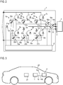
- Fig. 1 shows a circuit diagram of a first embodiment of a power conversion device 1, which converts a voltage applied to its input 2 DC voltage in a three-phase alternating current at its output 3, to which an electric machine 4 is included.
- switching means 5a, 5b, 5c are connected, which are constructed essentially identical and are explained in more detail below by way of example with reference to the switching means 5a.
- Fig. 1 Only for the switching means 5a and their associated components shown connections with a control device 6 of the power conversion device 1, which are not shown for reasons of clarity in the switching means 5b, 5c.
- the switching means 5a has two switching elements 7a, 8a which are connected as half bridges and which are formed by power transistors, for example IGBT or power MOSFET.
- the gate terminals are connected to the controller 6. By controlling the gate terminals controls the controller 6, the torque and the rotational speed of the electric machine. 4
- the switching elements 7a, 8a are each assigned a short-circuit detection device 9a, 10a with a measuring means 11a, 12a for detecting a voltage drop across the switching element 7a, 8a.
- This voltage is a collector-emitter voltage in the case of an IGBT and a drain-source voltage in the case of a power MOSFET.
- the switching means 5a a temperature detection device 13a associated with a temperature-dependent resistor as a temperature sensor, which detects a temperature in the vicinity of the switching elements 7a, 8a and / or from operating parameters of the power converter device 1, from which an instantaneous junction temperature of the transistors can be derived.
- first phase conductors 14a, 14b From the center taps of the switching means 5a, 5b go first phase conductors 14a, 14b, each of which a current measuring means 15a, 15b is assigned. These detect the alternating current flowing along a respective first phase conductor 14a, 14b as the first measured value and are connected to the control device 6 for evaluating the first measured values.
- a second phase conductor 16, which starts from the switching means 5c, no such current measuring means is assigned. The current intensity of the alternating current flowing along the second phase conductor 16 is calculated as arithmetic value by the control device 6 from the first measured values of the current measuring means 15a, 15b.
- the control device 6 is furthermore designed to make the calculation value describing the current along the second phase conductor 16 plausible on the basis of the second measured values of the short-circuit detection devices 9a-c, 10ac. This is necessary because safety requirements according to ISO 26262 are met by a redundant determination of the currents taken into account during the control along the phase conductors 14a, 14b, 16. For this purpose, the control device 6 calculates, based on a characteristic, the current flowing through a respective switching element 7a-c, 8a-c from the voltages described by the second measured values, and the voltages detected by the measuring means 11a-c, 12a-c, and plausibility the calculated value for the current flowing through the second phase conductor 16. If necessary, the control device 6 corrects the second measured values on the basis of the measured values of the temperature determining devices 13a-c.
- the control device 6 determines, for example, a deviation of the first measured values of the current measuring means 15a from the second measured values of the short-circuit detection device 9a and / or from the second measured values of the short-circuit detection device 10a. For this purpose, corresponding second measured values are registered with first measured values for a fault-free operating case of the current measuring means 15a and stored in a look-up table within a memory unit of the control device 6. If a gain drift of the current measuring means 15a now occurs, which has an effect on the calculated value due to the resulting incorrect first measured values, the control device 6 recognizes the gain drift on the basis of the deviation and determines the implausibility of the calculated value.
- erroneous first measured values of the current measuring means 15b can be detected on the basis of a deviation from the second measured values of the short-circuit detection device 9b and / or from the second measured values of the short-circuit detection device 10b.
- Another possibility for plausibility of the calculated value is to determine a deviation of the calculated value from a second measured value of the short circuit detection device 9c and / or the short circuit detection device 10c. If the currents flowing through the switching elements 7c, 8c deviate from the calculated value which describes the alternating current generated by the switching means 5c along the second phase conductor 16, an implausibility of the calculated value can be deduced.
- corresponding calculation values can be registered with second measured values and stored, for example, as a look-up table in the memory unit of the control device 6.
- the control device 6 outputs at an implausible calculated value an error signal via a signal output, not shown. As a further measure, it can deactivate the power converter device 1 in the event of a fault or correct the calculated value on the basis of a plurality of second measured values of a plurality of short-circuit detection devices 9a-c, 10a-c.
- Fig. 2 shows a circuit diagram of a second embodiment of a power conversion device 1, which differs from the in Fig. 1 shown embodiment differs in that the switching elements 7a-c, 8a-c are each formed as a transistor with a sense output 17a-c, 18a-c as a fourth transistor connection.
- the short-circuit detection devices 9a-c, 10a-c each have a resistor 19a-c, 20a-c connected to the sense output 17a-c, 18a-c, through which a measuring current correlating with the collector or drain current flows.
- measuring means 21 ac, 22a-c which detect the voltage dropped across a respective resistor 19a-c, 20a-c.
- Fig. 3 shows a schematic diagram of an embodiment of a motor vehicle 23, comprising an electric machine 4 for the partial or complete drive of the motor vehicle 23 and a power converter device 1 according to one of the embodiments explained above.
- the power converter device 1 is supplied on the input side by a high-voltage battery 24 with a DC voltage.
- the output side phase conductors 14a, 14b, 16 are connected to the electric machine 4.
Landscapes
- Engineering & Computer Science (AREA)
- Power Engineering (AREA)
- Microelectronics & Electronic Packaging (AREA)
- Inverter Devices (AREA)
- Control Of Ac Motors In General (AREA)
Applications Claiming Priority (1)
| Application Number | Priority Date | Filing Date | Title |
|---|---|---|---|
| DE102017206169.3A DE102017206169A1 (de) | 2017-04-11 | 2017-04-11 | Stromrichtereinrichtung für eine elektrische Maschine, Kraftfahrzeug und Verfahren zum Betreiben einer Stromrichtereinrichtung |
Publications (2)
| Publication Number | Publication Date |
|---|---|
| EP3389178A1 true EP3389178A1 (fr) | 2018-10-17 |
| EP3389178B1 EP3389178B1 (fr) | 2020-09-02 |
Family
ID=61750006
Family Applications (1)
| Application Number | Title | Priority Date | Filing Date |
|---|---|---|---|
| EP18163260.5A Active EP3389178B1 (fr) | 2017-04-11 | 2018-03-22 | Dispositif convertisseur de courant pour une machine électrique, véhicule automobile et procédé de fonctionnement d'un dispositif convertisseur de courant |
Country Status (4)
| Country | Link |
|---|---|
| US (1) | US10992208B2 (fr) |
| EP (1) | EP3389178B1 (fr) |
| CN (1) | CN108696233B (fr) |
| DE (1) | DE102017206169A1 (fr) |
Families Citing this family (3)
| Publication number | Priority date | Publication date | Assignee | Title |
|---|---|---|---|---|
| CN113394753B (zh) * | 2020-03-13 | 2025-08-26 | 欧姆龙(上海)有限公司 | 绝缘栅极双极型晶体管的保护装置和方法 |
| DE102021214350A1 (de) | 2021-12-15 | 2023-06-15 | Robert Bosch Gesellschaft mit beschränkter Haftung | Detektion von Kurzschlussströmen in stromgeregelten Endstufen |
| DE102023128896A1 (de) * | 2023-10-20 | 2025-04-24 | Seg Automotive Germany Gmbh | Verfahren zum Betreiben einer Stromrichterschaltung, Stromrichtersteuereinheit und Stromrichteranordnung |
Citations (7)
| Publication number | Priority date | Publication date | Assignee | Title |
|---|---|---|---|---|
| DE10249568A1 (de) * | 2002-10-24 | 2004-05-13 | Robert Bosch Gmbh | Fehleranalyse einer Wechselrichter-Schaltung |
| DE102005045323A1 (de) * | 2004-09-23 | 2006-04-13 | General Motors Corp. (N.D.Ges.D. Staates Delaware), Detroit | Positionssensorstörungstolerante Steuerung für Kraftfahrzeugvortriebssystem |
| US20080304197A1 (en) * | 2007-06-06 | 2008-12-11 | Nissan Motor Co., Ltd. | Drive circuit of voltage driven element |
| US20110221370A1 (en) * | 2010-03-11 | 2011-09-15 | Denso Corporation | Discharge control device for power conversion system |
| US20120068645A1 (en) * | 2010-09-17 | 2012-03-22 | Denso Corporation | Control apparatus for rotary electric machines |
| DE102012209276A1 (de) * | 2012-06-01 | 2013-12-05 | Robert Bosch Gmbh | Steuervorrichtung für Halbleiterschalter eines Wechselrichters und Verfahren zum Ansteuern eines Wechselrichters |
| DE102014107561A1 (de) * | 2013-06-12 | 2014-12-18 | Infineon Technologies Austria Ag | Strommessung und Überstromerkennung |
Family Cites Families (3)
| Publication number | Priority date | Publication date | Assignee | Title |
|---|---|---|---|---|
| US4480312A (en) * | 1981-08-14 | 1984-10-30 | Wingate Steven L | Temperature sensor/controller system |
| CN105388356B (zh) | 2014-08-22 | 2019-03-29 | 比亚迪股份有限公司 | 电流测量装置 |
| JP6191586B2 (ja) * | 2014-12-02 | 2017-09-06 | トヨタ自動車株式会社 | モータコントローラ、電動車両、及び、スイッチング素子の熱ストレス推定方法 |
-
2017
- 2017-04-11 DE DE102017206169.3A patent/DE102017206169A1/de not_active Withdrawn
-
2018
- 2018-03-22 EP EP18163260.5A patent/EP3389178B1/fr active Active
- 2018-04-05 US US15/945,776 patent/US10992208B2/en active Active
- 2018-04-10 CN CN201810314898.8A patent/CN108696233B/zh active Active
Patent Citations (7)
| Publication number | Priority date | Publication date | Assignee | Title |
|---|---|---|---|---|
| DE10249568A1 (de) * | 2002-10-24 | 2004-05-13 | Robert Bosch Gmbh | Fehleranalyse einer Wechselrichter-Schaltung |
| DE102005045323A1 (de) * | 2004-09-23 | 2006-04-13 | General Motors Corp. (N.D.Ges.D. Staates Delaware), Detroit | Positionssensorstörungstolerante Steuerung für Kraftfahrzeugvortriebssystem |
| US20080304197A1 (en) * | 2007-06-06 | 2008-12-11 | Nissan Motor Co., Ltd. | Drive circuit of voltage driven element |
| US20110221370A1 (en) * | 2010-03-11 | 2011-09-15 | Denso Corporation | Discharge control device for power conversion system |
| US20120068645A1 (en) * | 2010-09-17 | 2012-03-22 | Denso Corporation | Control apparatus for rotary electric machines |
| DE102012209276A1 (de) * | 2012-06-01 | 2013-12-05 | Robert Bosch Gmbh | Steuervorrichtung für Halbleiterschalter eines Wechselrichters und Verfahren zum Ansteuern eines Wechselrichters |
| DE102014107561A1 (de) * | 2013-06-12 | 2014-12-18 | Infineon Technologies Austria Ag | Strommessung und Überstromerkennung |
Also Published As
| Publication number | Publication date |
|---|---|
| DE102017206169A1 (de) | 2018-10-11 |
| CN108696233B (zh) | 2022-03-22 |
| US10992208B2 (en) | 2021-04-27 |
| US20180294697A1 (en) | 2018-10-11 |
| CN108696233A (zh) | 2018-10-23 |
| EP3389178B1 (fr) | 2020-09-02 |
Similar Documents
| Publication | Publication Date | Title |
|---|---|---|
| DE102011012588B4 (de) | Verfahren zum Überwachen des Verlusts einer Masseisolierung einer Elektromotorantriebsschaltung | |
| DE102015205627B4 (de) | Lastantriebsgerät | |
| DE102014107561B4 (de) | Strommessung und Überstromerkennung | |
| DE112012004834T5 (de) | Fehlererkennungsvorrichtung für eine Wechselrichterschaltung | |
| DE102014115881B4 (de) | Verfahren und Vorrichtung zum Vergrössern eines Stromerfassungsbereichs in einem System mit einem mehrphasigen Motor | |
| WO2011157468A1 (fr) | Procédé et dispositif pour surveiller la résistance d'isolation dans un réseau électrique non mis à la terre | |
| EP3389178B1 (fr) | Dispositif convertisseur de courant pour une machine électrique, véhicule automobile et procédé de fonctionnement d'un dispositif convertisseur de courant | |
| EP4092431B1 (fr) | Circuit de convertisseur et convertisseur | |
| WO2011157472A1 (fr) | Montage pour déterminer une variation de tension de potentiels de conducteur dans un réseau électrique non mis à la terre | |
| DE102013105439B4 (de) | Floatende beschaltung einer diode zur sperrschichttemperaturmessung | |
| EP3532857B1 (fr) | Dispositif et procédé pour le diagnostic de la détection d'un courant électrique polyphasé | |
| DE102013216831A1 (de) | Wandlerschaltung und Verfahren zum Betrieb einer solchen | |
| EP2510373B1 (fr) | Procédé et dispositif d'étalonnage de la mesure d'une tension sur un circuit de commande pour une machine électrique | |
| DE102019132455B4 (de) | Verfahren zur Strombestimmung und Anordnung zur Umsetzung des Verfahrens | |
| DE102011001185A1 (de) | Strommessung ohne Shunt-Widerstände | |
| DE112014003924T5 (de) | Überstromermittlungsvorrichtung und Überstromermittlungsverfahren | |
| WO2011157470A1 (fr) | Montage pour déterminer une variation de tension de potentiels de conducteur dans un réseau électrique non mis à la terre | |
| DE102017222689B4 (de) | Bidirektionaler Mehrphasengleichspannungswandler, Verfahren zur Funktionsüberwachung bei einem bidirektionalen Mehrphasengleichspannungswandler | |
| DE102017211105A1 (de) | Stromrichter zur Ansteuerung eines Elektromotors | |
| DE102023109195B3 (de) | Verfahren zur Plausibilisierung gemessener elektrischer Messgrößen einer Antriebseinheit | |
| DE102019208954A1 (de) | Verfahren zur Bestimmung von Phasenströmen eines Wechselrichters, Vorrichtung und Fahrzeug | |
| EP4409307B1 (fr) | Procédé et dispositif de détection pour la surveillance de capteurs de courant, et système d'entraînement électrique | |
| DE102024206339B3 (de) | Schaltungsvorrichtung, Stromrichter, elektrischer Achsantrieb, Kraftfahrzeug und Verfahren zum Betreiben einer Schaltungsvorrichtung | |
| DE102015104842A1 (de) | Redundantes Strommessverfahren für einen EPS-Wechselrichter | |
| DE102019100638B4 (de) | Strommesssystem für einen kommutierten Motor |
Legal Events
| Date | Code | Title | Description |
|---|---|---|---|
| PUAI | Public reference made under article 153(3) epc to a published international application that has entered the european phase |
Free format text: ORIGINAL CODE: 0009012 |
|
| STAA | Information on the status of an ep patent application or granted ep patent |
Free format text: STATUS: THE APPLICATION HAS BEEN PUBLISHED |
|
| AK | Designated contracting states |
Kind code of ref document: A1 Designated state(s): AL AT BE BG CH CY CZ DE DK EE ES FI FR GB GR HR HU IE IS IT LI LT LU LV MC MK MT NL NO PL PT RO RS SE SI SK SM TR |
|
| AX | Request for extension of the european patent |
Extension state: BA ME |
|
| STAA | Information on the status of an ep patent application or granted ep patent |
Free format text: STATUS: REQUEST FOR EXAMINATION WAS MADE |
|
| 17P | Request for examination filed |
Effective date: 20190417 |
|
| RBV | Designated contracting states (corrected) |
Designated state(s): AL AT BE BG CH CY CZ DE DK EE ES FI FR GB GR HR HU IE IS IT LI LT LU LV MC MK MT NL NO PL PT RO RS SE SI SK SM TR |
|
| GRAP | Despatch of communication of intention to grant a patent |
Free format text: ORIGINAL CODE: EPIDOSNIGR1 |
|
| STAA | Information on the status of an ep patent application or granted ep patent |
Free format text: STATUS: GRANT OF PATENT IS INTENDED |
|
| RIC1 | Information provided on ipc code assigned before grant |
Ipc: H02P 29/024 20160101AFI20200422BHEP Ipc: H02M 1/32 20070101ALI20200422BHEP |
|
| INTG | Intention to grant announced |
Effective date: 20200507 |
|
| GRAS | Grant fee paid |
Free format text: ORIGINAL CODE: EPIDOSNIGR3 |
|
| GRAA | (expected) grant |
Free format text: ORIGINAL CODE: 0009210 |
|
| STAA | Information on the status of an ep patent application or granted ep patent |
Free format text: STATUS: THE PATENT HAS BEEN GRANTED |
|
| AK | Designated contracting states |
Kind code of ref document: B1 Designated state(s): AL AT BE BG CH CY CZ DE DK EE ES FI FR GB GR HR HU IE IS IT LI LT LU LV MC MK MT NL NO PL PT RO RS SE SI SK SM TR |
|
| REG | Reference to a national code |
Ref country code: GB Ref legal event code: FG4D Free format text: NOT ENGLISH |
|
| REG | Reference to a national code |
Ref country code: AT Ref legal event code: REF Ref document number: 1309975 Country of ref document: AT Kind code of ref document: T Effective date: 20200915 Ref country code: CH Ref legal event code: EP |
|
| REG | Reference to a national code |
Ref country code: DE Ref legal event code: R096 Ref document number: 502018002311 Country of ref document: DE |
|
| REG | Reference to a national code |
Ref country code: IE Ref legal event code: FG4D Free format text: LANGUAGE OF EP DOCUMENT: GERMAN |
|
| REG | Reference to a national code |
Ref country code: LT Ref legal event code: MG4D |
|
| PG25 | Lapsed in a contracting state [announced via postgrant information from national office to epo] |
Ref country code: FI Free format text: LAPSE BECAUSE OF FAILURE TO SUBMIT A TRANSLATION OF THE DESCRIPTION OR TO PAY THE FEE WITHIN THE PRESCRIBED TIME-LIMIT Effective date: 20200902 Ref country code: SE Free format text: LAPSE BECAUSE OF FAILURE TO SUBMIT A TRANSLATION OF THE DESCRIPTION OR TO PAY THE FEE WITHIN THE PRESCRIBED TIME-LIMIT Effective date: 20200902 Ref country code: NO Free format text: LAPSE BECAUSE OF FAILURE TO SUBMIT A TRANSLATION OF THE DESCRIPTION OR TO PAY THE FEE WITHIN THE PRESCRIBED TIME-LIMIT Effective date: 20201202 Ref country code: GR Free format text: LAPSE BECAUSE OF FAILURE TO SUBMIT A TRANSLATION OF THE DESCRIPTION OR TO PAY THE FEE WITHIN THE PRESCRIBED TIME-LIMIT Effective date: 20201203 Ref country code: HR Free format text: LAPSE BECAUSE OF FAILURE TO SUBMIT A TRANSLATION OF THE DESCRIPTION OR TO PAY THE FEE WITHIN THE PRESCRIBED TIME-LIMIT Effective date: 20200902 Ref country code: LT Free format text: LAPSE BECAUSE OF FAILURE TO SUBMIT A TRANSLATION OF THE DESCRIPTION OR TO PAY THE FEE WITHIN THE PRESCRIBED TIME-LIMIT Effective date: 20200902 Ref country code: BG Free format text: LAPSE BECAUSE OF FAILURE TO SUBMIT A TRANSLATION OF THE DESCRIPTION OR TO PAY THE FEE WITHIN THE PRESCRIBED TIME-LIMIT Effective date: 20201202 |
|
| REG | Reference to a national code |
Ref country code: NL Ref legal event code: MP Effective date: 20200902 |
|
| PG25 | Lapsed in a contracting state [announced via postgrant information from national office to epo] |
Ref country code: PL Free format text: LAPSE BECAUSE OF FAILURE TO SUBMIT A TRANSLATION OF THE DESCRIPTION OR TO PAY THE FEE WITHIN THE PRESCRIBED TIME-LIMIT Effective date: 20200902 Ref country code: LV Free format text: LAPSE BECAUSE OF FAILURE TO SUBMIT A TRANSLATION OF THE DESCRIPTION OR TO PAY THE FEE WITHIN THE PRESCRIBED TIME-LIMIT Effective date: 20200902 Ref country code: RS Free format text: LAPSE BECAUSE OF FAILURE TO SUBMIT A TRANSLATION OF THE DESCRIPTION OR TO PAY THE FEE WITHIN THE PRESCRIBED TIME-LIMIT Effective date: 20200902 |
|
| PG25 | Lapsed in a contracting state [announced via postgrant information from national office to epo] |
Ref country code: SM Free format text: LAPSE BECAUSE OF FAILURE TO SUBMIT A TRANSLATION OF THE DESCRIPTION OR TO PAY THE FEE WITHIN THE PRESCRIBED TIME-LIMIT Effective date: 20200902 Ref country code: RO Free format text: LAPSE BECAUSE OF FAILURE TO SUBMIT A TRANSLATION OF THE DESCRIPTION OR TO PAY THE FEE WITHIN THE PRESCRIBED TIME-LIMIT Effective date: 20200902 Ref country code: PT Free format text: LAPSE BECAUSE OF FAILURE TO SUBMIT A TRANSLATION OF THE DESCRIPTION OR TO PAY THE FEE WITHIN THE PRESCRIBED TIME-LIMIT Effective date: 20210104 Ref country code: CZ Free format text: LAPSE BECAUSE OF FAILURE TO SUBMIT A TRANSLATION OF THE DESCRIPTION OR TO PAY THE FEE WITHIN THE PRESCRIBED TIME-LIMIT Effective date: 20200902 Ref country code: EE Free format text: LAPSE BECAUSE OF FAILURE TO SUBMIT A TRANSLATION OF THE DESCRIPTION OR TO PAY THE FEE WITHIN THE PRESCRIBED TIME-LIMIT Effective date: 20200902 |
|
| PG25 | Lapsed in a contracting state [announced via postgrant information from national office to epo] |
Ref country code: ES Free format text: LAPSE BECAUSE OF FAILURE TO SUBMIT A TRANSLATION OF THE DESCRIPTION OR TO PAY THE FEE WITHIN THE PRESCRIBED TIME-LIMIT Effective date: 20200902 Ref country code: AL Free format text: LAPSE BECAUSE OF FAILURE TO SUBMIT A TRANSLATION OF THE DESCRIPTION OR TO PAY THE FEE WITHIN THE PRESCRIBED TIME-LIMIT Effective date: 20200902 Ref country code: IS Free format text: LAPSE BECAUSE OF FAILURE TO SUBMIT A TRANSLATION OF THE DESCRIPTION OR TO PAY THE FEE WITHIN THE PRESCRIBED TIME-LIMIT Effective date: 20210102 |
|
| REG | Reference to a national code |
Ref country code: DE Ref legal event code: R097 Ref document number: 502018002311 Country of ref document: DE |
|
| PG25 | Lapsed in a contracting state [announced via postgrant information from national office to epo] |
Ref country code: SK Free format text: LAPSE BECAUSE OF FAILURE TO SUBMIT A TRANSLATION OF THE DESCRIPTION OR TO PAY THE FEE WITHIN THE PRESCRIBED TIME-LIMIT Effective date: 20200902 |
|
| PLBE | No opposition filed within time limit |
Free format text: ORIGINAL CODE: 0009261 |
|
| STAA | Information on the status of an ep patent application or granted ep patent |
Free format text: STATUS: NO OPPOSITION FILED WITHIN TIME LIMIT |
|
| 26N | No opposition filed |
Effective date: 20210603 |
|
| PG25 | Lapsed in a contracting state [announced via postgrant information from national office to epo] |
Ref country code: SI Free format text: LAPSE BECAUSE OF FAILURE TO SUBMIT A TRANSLATION OF THE DESCRIPTION OR TO PAY THE FEE WITHIN THE PRESCRIBED TIME-LIMIT Effective date: 20200902 Ref country code: DK Free format text: LAPSE BECAUSE OF FAILURE TO SUBMIT A TRANSLATION OF THE DESCRIPTION OR TO PAY THE FEE WITHIN THE PRESCRIBED TIME-LIMIT Effective date: 20200902 |
|
| PG25 | Lapsed in a contracting state [announced via postgrant information from national office to epo] |
Ref country code: IT Free format text: LAPSE BECAUSE OF FAILURE TO SUBMIT A TRANSLATION OF THE DESCRIPTION OR TO PAY THE FEE WITHIN THE PRESCRIBED TIME-LIMIT Effective date: 20200902 Ref country code: MC Free format text: LAPSE BECAUSE OF FAILURE TO SUBMIT A TRANSLATION OF THE DESCRIPTION OR TO PAY THE FEE WITHIN THE PRESCRIBED TIME-LIMIT Effective date: 20200902 |
|
| REG | Reference to a national code |
Ref country code: CH Ref legal event code: PL |
|
| REG | Reference to a national code |
Ref country code: BE Ref legal event code: MM Effective date: 20210331 |
|
| PG25 | Lapsed in a contracting state [announced via postgrant information from national office to epo] |
Ref country code: CH Free format text: LAPSE BECAUSE OF NON-PAYMENT OF DUE FEES Effective date: 20210331 Ref country code: LU Free format text: LAPSE BECAUSE OF NON-PAYMENT OF DUE FEES Effective date: 20210322 Ref country code: LI Free format text: LAPSE BECAUSE OF NON-PAYMENT OF DUE FEES Effective date: 20210331 Ref country code: IE Free format text: LAPSE BECAUSE OF NON-PAYMENT OF DUE FEES Effective date: 20210322 Ref country code: FR Free format text: LAPSE BECAUSE OF NON-PAYMENT OF DUE FEES Effective date: 20210331 |
|
| PG25 | Lapsed in a contracting state [announced via postgrant information from national office to epo] |
Ref country code: BE Free format text: LAPSE BECAUSE OF NON-PAYMENT OF DUE FEES Effective date: 20210331 |
|
| GBPC | Gb: european patent ceased through non-payment of renewal fee |
Effective date: 20220322 |
|
| PG25 | Lapsed in a contracting state [announced via postgrant information from national office to epo] |
Ref country code: GB Free format text: LAPSE BECAUSE OF NON-PAYMENT OF DUE FEES Effective date: 20220322 |
|
| PG25 | Lapsed in a contracting state [announced via postgrant information from national office to epo] |
Ref country code: NL Free format text: LAPSE BECAUSE OF NON-PAYMENT OF DUE FEES Effective date: 20200923 Ref country code: CY Free format text: LAPSE BECAUSE OF FAILURE TO SUBMIT A TRANSLATION OF THE DESCRIPTION OR TO PAY THE FEE WITHIN THE PRESCRIBED TIME-LIMIT Effective date: 20200902 |
|
| P01 | Opt-out of the competence of the unified patent court (upc) registered |
Effective date: 20230530 |
|
| PG25 | Lapsed in a contracting state [announced via postgrant information from national office to epo] |
Ref country code: HU Free format text: LAPSE BECAUSE OF FAILURE TO SUBMIT A TRANSLATION OF THE DESCRIPTION OR TO PAY THE FEE WITHIN THE PRESCRIBED TIME-LIMIT; INVALID AB INITIO Effective date: 20180322 |
|
| PG25 | Lapsed in a contracting state [announced via postgrant information from national office to epo] |
Ref country code: MK Free format text: LAPSE BECAUSE OF FAILURE TO SUBMIT A TRANSLATION OF THE DESCRIPTION OR TO PAY THE FEE WITHIN THE PRESCRIBED TIME-LIMIT Effective date: 20200902 |
|
| REG | Reference to a national code |
Ref country code: AT Ref legal event code: MM01 Ref document number: 1309975 Country of ref document: AT Kind code of ref document: T Effective date: 20230322 |
|
| PG25 | Lapsed in a contracting state [announced via postgrant information from national office to epo] |
Ref country code: TR Free format text: LAPSE BECAUSE OF FAILURE TO SUBMIT A TRANSLATION OF THE DESCRIPTION OR TO PAY THE FEE WITHIN THE PRESCRIBED TIME-LIMIT Effective date: 20200902 |
|
| PG25 | Lapsed in a contracting state [announced via postgrant information from national office to epo] |
Ref country code: AT Free format text: LAPSE BECAUSE OF NON-PAYMENT OF DUE FEES Effective date: 20230322 |
|
| PG25 | Lapsed in a contracting state [announced via postgrant information from national office to epo] |
Ref country code: AT Free format text: LAPSE BECAUSE OF NON-PAYMENT OF DUE FEES Effective date: 20230322 |
|
| PG25 | Lapsed in a contracting state [announced via postgrant information from national office to epo] |
Ref country code: MT Free format text: LAPSE BECAUSE OF FAILURE TO SUBMIT A TRANSLATION OF THE DESCRIPTION OR TO PAY THE FEE WITHIN THE PRESCRIBED TIME-LIMIT Effective date: 20200902 |
|
| PGFP | Annual fee paid to national office [announced via postgrant information from national office to epo] |
Ref country code: DE Payment date: 20260331 Year of fee payment: 9 |
|
| PGFP | Annual fee paid to national office [announced via postgrant information from national office to epo] |
Ref country code: AT Payment date: 20260410 Year of fee payment: 5 |