EP3389268B1 - Procédé et appareil d'acquisition d'informations de profondeur, et dispositif de collecte d'image - Google Patents
Procédé et appareil d'acquisition d'informations de profondeur, et dispositif de collecte d'image Download PDFInfo
- Publication number
- EP3389268B1 EP3389268B1 EP16884334.0A EP16884334A EP3389268B1 EP 3389268 B1 EP3389268 B1 EP 3389268B1 EP 16884334 A EP16884334 A EP 16884334A EP 3389268 B1 EP3389268 B1 EP 3389268B1
- Authority
- EP
- European Patent Office
- Prior art keywords
- image
- camera
- shooting object
- lens
- offset
- Prior art date
- Legal status (The legal status is an assumption and is not a legal conclusion. Google has not performed a legal analysis and makes no representation as to the accuracy of the status listed.)
- Active
Links
Images



Classifications
-
- H—ELECTRICITY
- H04—ELECTRIC COMMUNICATION TECHNIQUE
- H04N—PICTORIAL COMMUNICATION, e.g. TELEVISION
- H04N23/00—Cameras or camera modules comprising electronic image sensors; Control thereof
- H04N23/50—Constructional details
-
- H—ELECTRICITY
- H04—ELECTRIC COMMUNICATION TECHNIQUE
- H04N—PICTORIAL COMMUNICATION, e.g. TELEVISION
- H04N23/00—Cameras or camera modules comprising electronic image sensors; Control thereof
- H04N23/60—Control of cameras or camera modules
- H04N23/68—Control of cameras or camera modules for stable pick-up of the scene, e.g. compensating for camera body vibrations
- H04N23/682—Vibration or motion blur correction
- H04N23/685—Vibration or motion blur correction performed by mechanical compensation
- H04N23/687—Vibration or motion blur correction performed by mechanical compensation by shifting the lens or sensor position
-
- H—ELECTRICITY
- H04—ELECTRIC COMMUNICATION TECHNIQUE
- H04N—PICTORIAL COMMUNICATION, e.g. TELEVISION
- H04N13/00—Stereoscopic video systems; Multi-view video systems; Details thereof
- H04N13/20—Image signal generators
- H04N13/204—Image signal generators using stereoscopic image cameras
- H04N13/246—Calibration of cameras
-
- H—ELECTRICITY
- H04—ELECTRIC COMMUNICATION TECHNIQUE
- H04N—PICTORIAL COMMUNICATION, e.g. TELEVISION
- H04N17/00—Diagnosis, testing or measuring for television systems or their details
- H04N17/002—Diagnosis, testing or measuring for television systems or their details for television cameras
-
- G—PHYSICS
- G06—COMPUTING OR CALCULATING; COUNTING
- G06T—IMAGE DATA PROCESSING OR GENERATION, IN GENERAL
- G06T7/00—Image analysis
- G06T7/50—Depth or shape recovery
- G06T7/55—Depth or shape recovery from multiple images
-
- G—PHYSICS
- G06—COMPUTING OR CALCULATING; COUNTING
- G06T—IMAGE DATA PROCESSING OR GENERATION, IN GENERAL
- G06T7/00—Image analysis
- G06T7/50—Depth or shape recovery
- G06T7/55—Depth or shape recovery from multiple images
- G06T7/593—Depth or shape recovery from multiple images from stereo images
-
- G—PHYSICS
- G06—COMPUTING OR CALCULATING; COUNTING
- G06T—IMAGE DATA PROCESSING OR GENERATION, IN GENERAL
- G06T7/00—Image analysis
- G06T7/80—Analysis of captured images to determine intrinsic or extrinsic camera parameters, i.e. camera calibration
- G06T7/85—Stereo camera calibration
-
- H—ELECTRICITY
- H04—ELECTRIC COMMUNICATION TECHNIQUE
- H04N—PICTORIAL COMMUNICATION, e.g. TELEVISION
- H04N13/00—Stereoscopic video systems; Multi-view video systems; Details thereof
- H04N13/20—Image signal generators
- H04N13/204—Image signal generators using stereoscopic image cameras
- H04N13/239—Image signal generators using stereoscopic image cameras using two two-dimensional [2D] image sensors having a relative position equal to or related to the interocular distance
-
- H—ELECTRICITY
- H04—ELECTRIC COMMUNICATION TECHNIQUE
- H04N—PICTORIAL COMMUNICATION, e.g. TELEVISION
- H04N13/00—Stereoscopic video systems; Multi-view video systems; Details thereof
- H04N13/20—Image signal generators
- H04N13/204—Image signal generators using stereoscopic image cameras
- H04N13/243—Image signal generators using stereoscopic image cameras using three or more two-dimensional [2D] image sensors
-
- H—ELECTRICITY
- H04—ELECTRIC COMMUNICATION TECHNIQUE
- H04N—PICTORIAL COMMUNICATION, e.g. TELEVISION
- H04N23/00—Cameras or camera modules comprising electronic image sensors; Control thereof
- H04N23/45—Cameras or camera modules comprising electronic image sensors; Control thereof for generating image signals from two or more image sensors being of different type or operating in different modes, e.g. with a CMOS sensor for moving images in combination with a charge-coupled device [CCD] for still images
-
- H—ELECTRICITY
- H04—ELECTRIC COMMUNICATION TECHNIQUE
- H04N—PICTORIAL COMMUNICATION, e.g. TELEVISION
- H04N23/00—Cameras or camera modules comprising electronic image sensors; Control thereof
- H04N23/50—Constructional details
- H04N23/55—Optical parts specially adapted for electronic image sensors; Mounting thereof
-
- H—ELECTRICITY
- H04—ELECTRIC COMMUNICATION TECHNIQUE
- H04N—PICTORIAL COMMUNICATION, e.g. TELEVISION
- H04N23/00—Cameras or camera modules comprising electronic image sensors; Control thereof
- H04N23/60—Control of cameras or camera modules
- H04N23/67—Focus control based on electronic image sensor signals
-
- H—ELECTRICITY
- H04—ELECTRIC COMMUNICATION TECHNIQUE
- H04N—PICTORIAL COMMUNICATION, e.g. TELEVISION
- H04N23/00—Cameras or camera modules comprising electronic image sensors; Control thereof
- H04N23/60—Control of cameras or camera modules
- H04N23/68—Control of cameras or camera modules for stable pick-up of the scene, e.g. compensating for camera body vibrations
- H04N23/682—Vibration or motion blur correction
Definitions
- Embodiments of the present invention relate to the field of electronic technologies, and specifically, to a depth information obtaining method and apparatus, and an image acquisition device.
- depth information is related information of a perpendicular distance between a lens (Lens) of a camera module in an image acquisition device and a shooting object.
- the camera module may control movement of the lens according to the depth information, to implement focusing on the shooting object. Therefore, focusing accuracy depends on depth information obtaining accuracy.
- Optical image stabilization Optical Image Stabilization, OIS
- OIS Optical Image Stabilization
- US2015022669A describes that real-time registration of a camera array in an image capture device may be implemented in the field by adjusting a selected subset of independent parameters in a mapping function, termed registration coefficients, which have been determined to have the largest contribution to registration errors so that the array can be maintained in its initial factory-optimized calibrated state.
- registration coefficients a mapping function
- Such simplified pattern matching may be performed using images that are captured during normal camera array usage so that registration may be performed in real-time in the field without the need for specialized calibration targets.
- US2013162784A discloses a stereo camera which corrects for the effects of tolerances in the focal lengths of camera modules by using independent autofocus control for each lens.
- Embodiments of the present invention disclose a depth information obtaining method and apparatus, and an image acquisition device, so that depth information may be obtained accurately when multiple camera modules perform OIS, thereby implementing focusing accurately and quickly.
- a first aspect of the present invention is a depth information obtaining method according to appended claim 1.
- a second aspect of the present invention is a depth information obtaining apparatus according to appended claim 2.
- the depth information obtaining apparatus corrects the distance between the same shooting object in the two images respectively obtained by the two cameras, so that the image acquisition device finally obtains a relatively accurate depth of the object. This improves focusing accuracy of the cameras.
- the depth information obtaining apparatus when detecting that the cameras shake, may obtain the images captured by the first camera and the second camera, detect the initial distance between the target shooting object in the two images, correct the initial distance by using the offset difference between the first image and the second image, and finally substitute the corrected initial distance into a depth calculation formula, to determine the depth of the target shooting object.
- the depth information obtaining apparatus may correct the distance between the same shooting object in the images obtained by the two cameras, so that depth information, finally obtained according to the corrected distance, of the shooting object is relatively accurate. This can accurately and quickly implement focusing on the shooting object.
- the embodiments of the present invention disclose a depth information obtaining method and apparatus, and an image acquisition device, so that depth information may be obtained accurately when multiple camera modules perform OIS, thereby implementing focusing accurately and quickly.
- FIG. 1 is a schematic structural diagram of a camera module according to an embodiment of the present invention.
- the camera module includes: 1 a protective film, 2 a lens group, 3 a focus motor, 4 a light filter, and 5 a photosensitive element.
- the protective film 1 is configured to protect the lens group.
- the lens group 2 generally includes multiple lenses, and has an imaging function. Generally, the lens group has an OIS function.
- a relatively clear image may be obtained by moving the lens (collectively referred to as a lens in the embodiments of the present invention, and also referred to as the lens) of the lens group left and right.
- the focus motor 3 is mainly configured to drive the lens to move for focus assist.
- the light filter 4 is mainly configured to filter infrared rays, making a finally displayed image have a relatively small color difference.
- the photosensitive element 5 is mainly configured to convert an image obtained by the lens group 2 into an electronic image. A location of the photosensitive element is fixed. For an image acquisition device with multiple camera modules, it may be considered that photosensitive elements corresponding to all cameras are on a same plane.
- an image acquisition device with photographing and shooting functions such as a smartphone, a tablet computer, a personal digital assistant (Personal Digital Assistant, PDA), a mobile Internet device (Mobile Internet Device, MID), and a digital camera.
- PDA Personal Digital Assistant
- MID Mobile Internet Device
- digital camera a digital camera
- the image acquisition device includes multiple camera modules, the multiple camera modules are arranged side by side in the image acquisition device.
- the multiple camera modules may all have the OIS function, or only one camera has the OIS function. This is not limited in this embodiment of the present invention.
- the image acquisition device may calculate depth information of each shooting object in the image.
- the image acquisition device may perform focusing on the shooting object according to a depth of the shooting object.
- the image acquisition device includes the multiple camera modules, images captured by the multiple camera modules are finally fused into one image, so that the captured image is more clear, and can better satisfy a shooting requirement of a user. It should be noted that this solution is proposed on a basis that multiple cameras perform OIS.
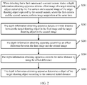
- FIG. 2 is a schematic flowchart of the depth information obtaining method according to this embodiment of the present invention.
- the method shown in FIG. 2 may be applied to an image acquisition device.
- the image acquisition device includes a first camera and a second camera.
- the depth information obtaining method may include the following steps.
- a depth information obtaining apparatus obtains a first image of a target shooting object captured by the first camera and a second image of the target shooting object captured by the second camera, where the first camera and the second camera perform image acquisition at the same time.
- the first camera and the second camera capture images in respective fields of view in real time.
- the first camera and the second camera shake at the same time. Therefore, when the depth information obtaining apparatus detects that the first camera and the second camera shake (specifically, a gyroscope may be used to detect whether shaking occurs), the first camera and the second camera capture images from a current environment at the same time, and obtain a first image of the first camera and a second image of the second camera respectively, so that the depth information obtaining apparatus obtains the first image and the second image.
- Both the first image and the second image include a target shooting object.
- the first image and the second image are electronic images obtained by converting, by photosensitive elements of the first camera and the second camera, images obtained by lenses of the cameras.
- the target shooting object is any shooting object existing in both the first image and the second image, such as a human face, a building, or an animal. This is not limited in this embodiment of the present invention.
- the first camera includes a first lens
- the second camera includes a second lens.
- the depth information obtaining apparatus obtains a moving distance af_offset 1 of the first lens and a moving distance af_offset 2 of the second lens.
- af_offset 1 is a scalar distance between a current location of the first lens and a first start location of the first lens on a Z-axis of a three-dimensional coordinate system, that is, a relative moving distance between the current location at which the first lens captures the first image and the first start location of the first lens.
- af_offset 2 is a scalar distance between a current location of the second lens and a second start location of the second lens on the Z-axis of the three-dimensional coordinate system, that is, a relative moving distance between the current location at which the second lens captures the second image and the second start location of the second lens.
- the first start location is mainly a location, of the first lens, at which a perpendicular distance between the first lens and the photosensitive element of the first camera is one times a focal length of the first lens.
- the second start location is mainly a location, of the second lens, at which a perpendicular distance between the second lens and the photosensitive element of the second camera is one times a focal length of the second lens.
- a minimum distance between the first lens and the photosensitive element of the first camera is generally a distance of one times the focal length of the first lens.
- a minimum distance between the second camera and the photosensitive element of the second lens is similarly a distance of one times the focal length of the second lens.
- the depth information obtaining apparatus detects an initial distance between the target shooting object in the first image and the target shooting object in the second image.
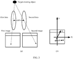
- FIG. 3 is a schematic diagram of a dual-camera shooting scenario according to an embodiment of the present invention.
- the depth information obtaining apparatus may create a three-dimensional coordinate system by using a plane on which the photosensitive elements of the cameras are located as an XY-plane and using a direction along which the lenses of the cameras are perpendicular to the photosensitive elements as a Z-axis.
- a location of an origin of the three-dimensional coordinate system is not limited in this embodiment of the present invention. Therefore, when obtaining the first image captured by the first lens and the second image captured by the second lens (as shown in FIG. (a) of FIG. 3 ), the depth information obtaining apparatus may make the first image and the second image overlapped and mapped on the XY-plane of the three-dimensional coordinate system (as shown in FIG. (b) of FIG. 3 ).
- the depth information obtaining apparatus may detect the initial distance between the target shooting object in the first image and the target shooting object in the second image.
- the initial distance is generally a vector distance and is represented by d 0 .
- the initial distance is specifically a coordinate distance, obtained by the depth information obtaining apparatus after the depth information obtaining apparatus makes the first image and the second image overlapped and mapped onto the XY-plane, between the target shooting object in the two images (that is, a distance d0 between two black spots in the first image and the second image shown in FIG. (b) of FIG. 3 ).
- the initial distance d 0 may be a vector distance, obtained by the depth information obtaining apparatus after the depth information obtaining apparatus makes the two images overlapped and mapped onto the XY-plane of the three-dimensional coordinate system, between coordinates of a same characteristic pixel of the target shooting object in the two images.
- the initial distance d 0 may be a distance obtained as follows: On the XY-plane, the depth information obtaining apparatus selects multiple characteristic pixels from the first image; for each of the characteristic pixels, selects, from the second image, a pixel with a same characteristic as the characteristic pixel; calculates a vector distance between coordinates of the two pixels; and finally uses an average value of vector distances of multiple groups of pixels with same characteristics as the initial distance d 0 between the target shooting object in the first image and the target shooting object in the second image. This is not limited in this embodiment of the present invention.
- a specific manner of detecting the initial distance between the target shooting object in the first image and the target shooting object in the second image by the depth information obtaining apparatus may be: detecting the initial distance d 0 between the target shooting object in the first image and the target shooting object in the second image that are mapped on the XY-plane of the three-dimensional coordinate system. On the XY-plane of the three-dimensional coordinate system created in FIG.
- the depth information obtaining apparatus may first make the first image and the second image overlap with each other; select a characteristic pixel P 1 from the target shooting object in the first image, with coordinates, say (P 1x ,P 1y ); and select, from the target shooting object in the second image, a pixel P 2 with a same characteristic as the characteristic pixel, with coordinates, say (P 2x ,P 2y ).
- the depth information obtaining apparatus may calculate, according to the coordinates of P 1 and P 2 , the initial vector distance d 0 , say (d 0x ,d 0y ), of the two pixels.
- d 0x may be P 1x - P 2x or P 2x - P 1x .
- the depth information obtaining apparatus may further use a central point of the first image in the photosensitive element of the first camera to create a three-dimensional coordinate system; use a central point of the second image in the photosensitive element of the second camera to create another three-dimensional coordinate system; then separately obtain coordinates, in the two coordinate systems, of a same characteristic pixel of the target shooting object in the first image and the target shooting object in the second image; and finally calculate a vector distance between coordinates of the target shooting object in the first image and coordinates of the target shooting object in the second image.
- the two coordinate systems have a same unit distance and same X-, Y-, and Z-axis directions except different origins of coordinates.
- the depth information obtaining apparatus may create a three-dimensional coordinate system for each of the two cameras, or may create only one three-dimensional coordinate system. This is not limited in this embodiment of the present invention. For ease of description, creating one three-dimensional coordinate system is used for description in this specification. Details are not further described in this embodiment of the present invention.
- the depth information obtaining apparatus determines an offset difference between the first image and the second image.
- the offset difference between the first image and the second image can be understood as a difference between an offset value of the first image and an offset value of the second image.
- the depth information obtaining apparatus may separately determine coordinates locations of the first image and the second image on the XY-plane of the three-dimensional coordinate system; obtain a coordinates location of a third image captured by the first camera and a coordinates location of a fourth image captured by the second camera, where the coordinates locations are prerecorded when the cameras do not shake; separately calculate a relative coordinates offset, say d 1 , between the coordinates location of the first image and the coordinates location of the third image, and a relative coordinates offset, say d 2 , between the coordinates location of the second image and the coordinates location of the fourth image.
- a difference between d 1 and d 2 is the offset difference between the first image and the second image.
- d 1 , d 2 , and the offset difference all are vectors.
- the offset value d 1 is generally a relative vector offset between the first image and an image that is captured by the first lens at the first start location
- the offset value d 2 is generally a relative vector offset between the second image and an image that is captured by the second lens at the second start location.
- the depth information obtaining apparatus prerecords coordinates of an image, captured by the first lens at one times of a focal length (that is, the first start location) of the first lens, mapped on the XY-plane in the three-dimensional coordinate system (which may be specifically recording a coordinates location of each pixel in the image).
- the first camera performs OIS
- the first lens moves on the XY-plane of the three-dimensional coordinate system.
- a relative offset between the first image captured by the first camera and an image captured at the first start location may occur on the XY-plane.
- the depth information obtaining apparatus selects, from the first image, a pixel at a same location as the pixel in the image captured at the first start location, with coordinates, say (q' 1x ,q' 1y ).
- the offset difference is d 1 - d 2 .
- the offset difference is d 2 - d 1 .
- a method for calculating an offset difference needs to be consistent with that for calculating d 0 .
- the initial distance may be a relative vector distance between the target shooting object in the first image and the target shooting object in the second image
- the offset difference is a relative offset difference between the offset value of the first image and the offset value of the second image
- the initial distance may be a relative vector distance between the target shooting object in the second image and the target shooting object in the first image
- the offset difference is a relative offset difference between the offset value of the second image and the offset value of the first image. This is not limited in this embodiment of the present invention.
- the depth information obtaining apparatus corrects the initial distance by using the offset difference.
- the depth information obtaining apparatus may correct d 0 by using the offset difference to obtain a corrected distance d 0 ', that is, (d 0x ', d 0y ').
- the depth information obtaining apparatus determines a depth of the target shooting object according to the corrected initial distance.
- an actual distance between the first lens and the second lens is D 0 ' (as shown in FIG. 3 ).
- the depth information apparatus generally cannot directly obtain the actual distance between the two lenses. Therefore, generally, in the prior art, when the depth of the shooting object is calculated, a vector distance between the first start location and the second start location is generally used as an actual vector distance between the first lens and the second lens. As a result, finally obtained depth information is not accurate, or even there is a large difference between the finally obtained depth information and actual depth information.
- the depth information obtaining apparatus may generally directly obtain the vector distance D 0 between the first start location and the second start location.
- the vector distance D 0 on the XY-plane may be represented as (D 0x ,D 0y ). Therefore, the depth information obtaining apparatus may calculate the depth of the target shooting object by using the corrected distance d 0 ' and D 0 . In this way, the finally obtained depth information is relatively accurate.
- D 0 may be obtained by subtracting coordinates of the second start location on the XY-plane from coordinates of the first start location on the XY-plane, or may be obtained by subtracting coordinates of the first start location on the XY-plane from coordinates of the second start location on the XY-plane.
- a method for calculating D 0 also needs to be consistent with that for calculating d 0 . Details are not further described herein in this embodiment of the present invention.
- the depth information obtaining apparatus may calculate the depth of the target shooting object according to the depth calculation formula.
- both the first camera and the second camera have the OIS function
- OIS the offset value of the first image
- d 2 of the second image is 0.
- the offset value d 1 is not 0, and the offset value d 2 of the second image captured by the camera with no OIS function (the second camera) is 0. That is, this solution is not only applicable to an image acquisition device of which two cameras have the OIS function, but also applicable to an image acquisition device of which only one camera has the OIS function. This is not limited in this embodiment of the present invention.
- this solution can be not only applicable to an image acquisition device that has two cameras and of which at least one of the cameras has the OIS function, but also applicable to an image acquisition device that has three or more cameras and of which at least one of the cameras has the OIS function.
- the depth information obtaining apparatus may combine every two of the three cameras, and obtain depths of the target shooting object by using two cameras in each combination, to obtain three depths.
- the depth information obtaining apparatus may use an average depth of the three depths as an actual depth of the target shooting object. This is not limited in this depths of the target shooting object by using two cameras in each combination, to obtain three depths.
- the depth information obtaining apparatus may use an average depth of the three depths as an actual depth of the target shooting object. This is not limited in this embodiment of the present invention.
- the depth information obtaining apparatus may obtain the images captured by the first camera and the second camera, detect the initial distance between the target shooting object in the two images, correct the initial distance by using the offset difference between the first image and the second image, and finally substitute the corrected initial distance into the depth calculation formula, to determine the depth of the target shooting object.
- the depth information obtaining apparatus may correct the distance between the same shooting object in the images obtained by the two cameras, so that depth information, finally obtained according to the corrected distance, of the shooting object is relatively accurate. This can accurately and quickly implement focusing on the shooting object.
- FIG. 4 is a schematic flowchart of the another depth information obtaining method according to this embodiment of the present invention.
- the method shown in FIG. 4 may be applied to an image acquisition device.
- the image acquisition device includes a first camera and a second camera.
- the depth information obtaining method may include the following steps.
- a depth information obtaining apparatus obtains a first image of a target shooting object captured by the first camera and a second image of the target shooting object captured by the second camera, where the first camera and the second camera perform image acquisition at the same time.
- the depth information obtaining apparatus detects an initial distance between the target shooting object in the first image and the target shooting object in the second image.
- the depth information obtaining apparatus determines an offset difference between the first image and the second image.
- a specific manner of determining the offset difference between the first image and the second image by the depth information obtaining apparatus may include the following steps.
- the depth information obtaining apparatus When detecting that the first camera and the second camera shake, the depth information obtaining apparatus obtains a first offset of a first lens and a second offset of a second lens.
- the depth information obtaining apparatus determines an offset value of the first image according to the first offset, determines an offset value of the second image according to the second offset, and obtains an offset difference between the offset value of the first image and the offset value of the second image.
- the first offset of the first lens may be understood as a vector offset between a current location of the first lens and a first start location on the XY-plane, where the vector offset is marked as L 1 .
- the second offset of the second lens may be understood as a vector offset between a current location of the second lens and a second start location on the XY-plane, where the vector offset is marked as L 2 .
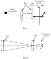
- FIG. 5 is a schematic diagram of a scenario in which a lens moves when a camera performs OIS according to an embodiment of the present invention.
- a location, represented by a dotted line, of a lens is a start location of the lens
- a location, represented by a solid line, of the lens is a lens location (that is, a current location of the lens) at which the lens captures an image with the target shooting object while performing OIS.
- coordinates of the start location on the XY-plane is subtracted from coordinates of the current location of the lens on the XY-plane to obtain a relative offset L between the lens and the start location, and the offset is a vector.
- a Z-axis coordinate of the start location is subtracted from a Z-axis coordinate of the current location of the lens to obtain a moving distance af_offset between the lens and the start location.
- the first lens is used as an example.
- the start location shown in FIG. 5 is a first start location (assuming that coordinates are (L 1x , L 1y , L 1z )) of the first lens
- the current location shown in FIG. 5 is a current location (assuming that coordinates are (L' 1x , L' 1y , L' 1z )) of the first lens.
- a moving distance af_offset 1 on the Z-axis between the current location of the first lens and the first start location is
- the first offset L 1 on the XY-plane between the current location of the first lens and the first start location is (L' 1x - L 1x , L' 1y - L 1y ), which is a vector distance.
- a moving distance af_offset 2 of the second lens may be obtained, that is
- the second offset L 2 of the second lens may be obtained, that is (L' 2x - L 2x , L' 2y - L 2y ).
- both the moving distance and the offset of the lens mentioned in this specification refer to a distance between optical centers of the lens (convex lens). Details are not further described in this embodiment of the present invention.
- the depth information obtaining apparatus records offset scales of the first lens and the second lens on the XY-plane by mainly using Hall effect sensors or lasers.
- offset directions may be recorded. Offsets of the lenses are obtained according to the offset directions of the lenses and distances corresponding to the scales.
- the depth information obtaining apparatus may further calibrate a Hall scale.
- a specific manner may be as follows: For each camera (a focal length is given, marked as f), the depth information obtaining apparatus may control a lens of the camera to capture a table whose shooting depth is given (marked as S), controls the lens to move along a primary optical axis of the lens. First, the lens is moved one Hall scale, and the table is captured, so that a width (marked as d) of the table on a photosensitive element may be obtained.
- the depth information obtaining apparatus can separately calculate the offset value d 1 of the first image and the offset value d 2 of the second image according to a relationship between an offset of a lens and an offset of an image.
- the offsets of the first lens and the second lens are first obtained, and the offset value of the first image and the offset value of the second image are separately calculated according to the foregoing calculation formulas, then an offset difference between the two images are obtained. Therefore, correction of a distance between the target shooting object in the two images is more accurate, thereby improving accuracy of depth information.
- the depth information obtaining apparatus corrects the initial distance by using the offset difference.
- the depth information obtaining apparatus determines a depth of the target shooting object according to the corrected initial distance.
- the depth information obtaining apparatus may further calibrate focal lengths of the first lens and the second lens in advance.
- a specific manner may be as follows:
- FIG. 6 is a schematic diagram of a focal length calibration method of a lens according to an embodiment of the present invention.
- the depth information obtaining apparatus may control a lens of the camera to capture a table whose shooting depth is given (marked as S) and whose width is given (marked as D), and control the lens to move along a primary optical axis of the lens.
- the lens is moved to a location at which an image has a highest contrast, the table is captured, and a width (marked as d) of the table on the photosensitive element may be obtained.
- the depth information obtaining apparatus may obtain a moving distance af_offset of the lens on the Z-axis relative to a start location of the lens.
- the depth information obtaining apparatus may further calculate a focal length of each camera in this manner.
- a difference between focal lengths of the two cameras may be managed and controlled.
- a difference between focal lengths, calibrated in the foregoing manner, of the two cameras is set to not greater than a preset focal length threshold.
- the preset focal length threshold may be 0.01. If the difference is greater than the preset focal length threshold, for example, f 1 ⁇ f 2 f 1 > 0.01 or f 2 ⁇ f 1 f 2 > 0.01 , it indicates that focal length calibration fails this time, and a camera or a lens is replaced in the production line.
- the depth information obtaining apparatus may calculate the depth of the target shooting object in the image by using a calibrated focal length.
- the depth information obtaining apparatus receives an instruction for focusing on the target shooting object.
- the depth information obtaining apparatus may obtain a depth of each shooting object in the foregoing manner of obtaining the depth of the target shooting object
- Mobile phone photographing is used as an example.
- the depth information obtaining apparatus may receive an instruction for focusing on the target shooting object. That is, the focusing instruction received by the depth information obtaining apparatus may be triggered by the user, or may be obtained by means of image analysis. This is not limited in this embodiment of the present invention.
- the mobile phone when the mobile phone starts a portrait mode for photographing, after obtaining a depth of each shooting object in a current scenario, the mobile phone may automatically identify that the target shooting object is a person, and an instruction for focusing on the person in the current scenario may be generated. If the user wants to focus on a plant in the background, the user may tap the plant on the image preview screen of the mobile phone, the depth information obtaining apparatus receives an instruction for focusing on the plant.
- the depth information obtaining apparatus obtains a first moving distance that is of the first lens and that is corresponding to the depth, and obtains a second moving distance that is of the second lens and that is corresponding to the depth.
- the depth information obtaining apparatus may calculate, according to the obtained depth Depth of the target shooting object, the first moving distance af_offset 1 ' of the first lens on the Z-axis relative to the first start location. Similarly, the depth information obtaining apparatus may obtain the second moving distance af_offset 2 ' of the second lens on the Z-axis relative to the second start location.
- the depth Depth of the target shooting object is S in FIG. 6
- af_offset 2 ′ f 2 ⁇ f 2 + af _ offset 2 ⁇ D 0 f 2 + af _ offset 2 ⁇ D 0 ⁇ f 2 ⁇ d 0 ′ .
- the depth information obtaining apparatus determines a focus location of the first lens according to the first moving distance, determines a focus location of the second lens according to the second moving distance, and controls the first lens and the second lens to move to respective focus locations.
- the depth information obtaining apparatus may determine, according to the first moving distance af_offset 1 ', the focus location at which the first lens performs focusing on the target shooting object; determine, according to the second moving distance af_offset 2 ', the focus location at which the second lens performs focusing on the target shooting object, and control the first lens and the second lens to move to respective focus locations, to implement focusing on the target shooting object.
- the depth information obtaining apparatus may further blur another shooting object according to a difference between a depth of the another shooting object and the depth of the target shooting object. Specifically, the depth information obtaining apparatus blurs the another shooting object that is different from the target shooting object (that is, a focus point) by using a blurring algorithm, a shooting object farther away from the target shooting object receives a higher degree of blurring, and a shooting object nearer by the target shooting object receives a lower degree of blurring.
- the depth information obtaining apparatus may detect the first offset of the first lens on the XY-plane relative to the first start location and the second offset of the second lens on the XY-plane relative to the second start location, to determine the offset value of the first image and the offset value of the second image.
- the initial distance between the target shooting object in the first image and the target shooting object in the second image can be corrected more accurately, and the finally calculated depth of the target shooting object is more accurate.
- the depth of the target shooting object is relatively accurate. Therefore, focusing accuracy and a focusing speed of the target shooting object can be increased, and imaging quality of the image acquisition device can be improved.
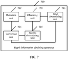
- FIG. 7 is a schematic structural diagram of the depth information obtaining apparatus according to this embodiment of the present invention.
- the depth information obtaining apparatus 700 shown in FIG. 7 may be applied to an image acquisition device.
- the image acquisition device includes a first camera and a second camera.
- the depth information obtaining apparatus 700 may include the following units:
- the initial distance may be a relative vector distance between the target shooting object in the first image and the target shooting object in the second image, and the offset difference is a relative offset difference between an offset value of the first image and an offset value of the second image.
- the initial distance may be a relative vector distance between the target shooting object in the second image and the target shooting object in the first image, and the offset difference is a relative offset difference between the offset value of the second image and the offset value of the first image. This is not limited in this embodiment of the present invention.
- the depth information obtaining apparatus corrects the distance between the same shooting object in the two images respectively obtained by the two cameras, so that the image acquisition device finally obtains a relatively accurate depth of the object. This improves focusing accuracy of the cameras.
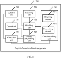
- FIG. 8 is a schematic structural diagram of another depth information obtaining apparatus according to an embodiment of the present invention.
- the depth information obtaining apparatus 700 shown in FIG. 8 is obtained by means of optimization performed based on the depth information obtaining apparatus 700 shown in FIG. 7 .
- the depth information obtaining apparatus 700 may further include the following units.
- a receiving unit 706 is configured to receive an instruction for focusing on the target shooting object.
- the obtaining unit 701 is further configured to: in response to the focusing instruction, obtain a first moving distance that is of a first lens and that is corresponding to the depth, and obtain a second moving distance that is of a second lens and that is corresponding to the depth.
- the second determining unit 705 is further configured to determine a focus location of the first lens according to the first moving distance, and determine a focus location of the second lens according to the second moving distance.
- a control unit 707 is configured to control the first lens and the second lens to move to respective focus locations.
- the depth information obtaining apparatus 700 may obtain distances for which the lenses need to move and that are corresponding to the depth, determine focus locations of the lenses according to respective moving distances, and then move the lenses to the focus locations respectively corresponding to the distances. This can accurately and quickly implement focusing on the target shooting object.
- the first determining unit 703 may include an obtaining subunit 7031 and a determining subunit 7032.
- the obtaining subunit 7031 is configured to: when the depth information obtaining apparatus 700 detects that the first camera and the second camera shake, obtain a first offset of the first lens and a second offset of the second lens.
- the determining subunit 7032 is configured to determine an offset value of the first image according to the first offset, and determine an offset value of the second image according to the second offset, to obtain an offset difference between the offset value of the first image and the offset value of the second image.
- the depth information obtaining apparatus when detecting that the cameras shake, may obtain the images captured by the first camera and the second camera, detect the initial distance between the target shooting object in the two images, correct the initial distance by using the offset difference between the first image and the second image, and finally substitute the corrected initial distance into a depth calculation formula to determine the depth of the target shooting object.
- the depth information obtaining apparatus may correct the distance between the same shooting object in the images obtained by the two cameras, so that depth information, finally obtained according to the corrected distance, of the shooting object is relatively accurate. This can accurately and quickly implement focusing on the shooting object.
- FIG. 9 is a schematic structural diagram of the image acquisition device according to this embodiment of the present invention.
- the image acquisition device 900 shown in FIG. 9 may include: a first camera 901, a second camera 902, at least one processor 903 such as a CPU, a receiver 904, a sender 905, a display screen 906, and a communications bus 907.
- the sender 905 is configured to send various data signals such as an image to an external device.
- the display screen 906 is configured to display images captured by the first camera 901 and the second camera 902.
- the display screen may be a touch display screen.
- the communications bus 907 is configured to implement communication connections among these components such as the first camera 901, the second camera 902, the processor 903, the receiver 904, the sender 905, and the display screen 906.
- the first camera 901 is configured to: when the image acquisition device 900 detects that the first camera and the second camera shake, capture a first image of a target shooting object.
- the second camera 902 is configured to: when the image acquisition device 900 detects that the first camera and the second camera shake, capture a second image of the target shooting object, where the first camera and the second camera perform image acquisition at the same time.
- the processor 903 is configured to obtain the first image and the second image, and detect an initial distance between the target shooting object in the first image and the target shooting object in the second image.
- the processor 903 is further configured to determine an offset difference between the first image and the second image, and correct the initial distance by using the offset difference.
- the processor 903 is further configured to determine a depth of the target shooting object according to the corrected initial distance.
- the initial distance may be a relative vector distance between the target shooting object in the first image and the target shooting object in the second image, and the offset difference is a relative offset difference between an offset value of the first image and an offset value of the second image.
- the initial distance may be a relative vector distance between the target shooting object in the second image and the target shooting object in the first image, and the offset difference is a relative offset difference between the offset value of the second image and the offset value of the first image. This is not limited in this embodiment of the present invention.
- the image acquisition device 900 corrects the distance between the same shooting object in the two images respectively obtained by the two cameras, so that the image acquisition device finally obtains a relatively accurate depth of the object. This improves focusing accuracy of the cameras.
- a specific manner of determining the offset difference between the first image and the second image by the processor 903 may be:
- the receiver 904 is configured to receive an instruction for focusing on the target shooting object.
- the processor 903 is further configured to: in response to the focusing instruction, obtain a first moving distance that is of the first lens and that is corresponding to the depth, and obtain a second moving distance that is of the second lens and that is corresponding to the depth.
- the processor 903 is further configured to determine a focus location of the first lens according to the first moving distance, and determine a focus location of the second lens according to the second moving distance.
- the processor 903 is further configured to control the first lens and the second lens moving distances, and then move the lenses to the respective focus locations. This can accurately and quickly implement focusing on the target shooting object.
- the image acquisition device may include the first camera, the second camera, the processor, and the receiver.
- the first camera and the second camera may capture the first image and the second image of the target shooting object, respectively.
- the processor may obtain the first image and the second image, detect the initial distance between the target shooting object in the two images, correct the initial distance by using the offset difference between the first image and the second image, and finally substitute the corrected initial distance into a depth calculation formula, to determine the depth of the target shooting object.
- the image acquisition device may correct the distance between the same shooting object in the images obtained by the two cameras, so that depth information, finally obtained according to the corrected distance, of the shooting object is relatively accurate. This can accurately and quickly implement focusing on the shooting object.
- the units of the embodiments of the present invention may be implemented by using a universal integrated circuit, such as a CPU (Central Processing Unit, central processing unit) or an ASIC (Application Specific Integrated Circuit, application-specific integrated circuit).
- a universal integrated circuit such as a CPU (Central Processing Unit, central processing unit) or an ASIC (Application Specific Integrated Circuit, application-specific integrated circuit).
- a person of ordinary skill in the art may understand that all or a part of the processes of the methods in the embodiments may be implemented by a computer program instructing relevant hardware.
- the program may be stored in a computer-readable storage medium. When the program runs, the processes of the methods in the embodiments are performed.
- the foregoing storage medium may be a magnetic disk, an optical disc, a read-only memory (Read-Only Memory, ROM), or a random access memory (Random Access Memory, RAM).
Landscapes
- Engineering & Computer Science (AREA)
- Signal Processing (AREA)
- Multimedia (AREA)
- Theoretical Computer Science (AREA)
- General Physics & Mathematics (AREA)
- Physics & Mathematics (AREA)
- Computer Vision & Pattern Recognition (AREA)
- Health & Medical Sciences (AREA)
- Biomedical Technology (AREA)
- General Health & Medical Sciences (AREA)
- Human Computer Interaction (AREA)
- Studio Devices (AREA)
- Measurement Of Optical Distance (AREA)
- Automatic Focus Adjustment (AREA)
- Adjustment Of Camera Lenses (AREA)
- Focusing (AREA)
- Length Measuring Devices By Optical Means (AREA)
Claims (2)
- Procédé d'obtention d'informations de profondeur, pour un dispositif d'acquisition d'images, dans lequel le dispositif d'acquisition d'images comprend un premier appareil photo comprenant une première lentille et un second appareil photo comprenant une seconde lentille, les lentilles ayant des longueurs focales légèrement différentes, le procédé comprenant :la détection (S201) du tremblement du premier appareil photo et du second appareil photo à l'aide d'un gyroscope commun au premier appareil photo et au second appareil photo,l'obtention d'une première image d'un objet de prise de vue cible capturée par le premier appareil photo et d'une deuxième image de l'objet de prise de vue cible capturée par le second appareil photo, dans lequel le premier appareil photo et le second appareil photo effectuent simultanément une acquisition d'image ;si un tremblement de l'appareil photo est détecté :
la détection (S202) d'une distance initiale entre l'objet de prise de vue cible dans la première image et l'objet de prise de vue cible dans la deuxième image ; en superposant la première image et la deuxième image et en mappant la première et la deuxième images sur un plan XY d'un système de coordonnées tridimensionnelles et en identifiant une distance vectorielle entre les deux mêmes pixels caractéristiques de l'objet de prise de vue cible dans les première et deuxième images la détermination (S203) d'une différence de décalage entre la première image et la deuxième image ; dans lequel la détermination (S203) d'une différence de décalage comprend :
après l'obtention de la première image et de la deuxième image, la détermination des emplacements de coordonnées de la première image et de la deuxième image sur le plan XY du système de coordonnées tridimensionnelles ; l'obtention d'un emplacement de coordonnées d'une troisième image capturée par le premier appareil photo et d'un emplacement de coordonnées d'une quatrième image capturée par le second appareil photo, où les emplacements de coordonnées sont préenregistrés lorsque les appareils photo ne tremblent pas ; le calcul d'un décalage de coordonnées relatif d1 entre l'emplacement de coordonnées de la première image et l'emplacement de coordonnées de la troisième image et d'un décalage de coordonnées relatif d2 entre l'emplacement de coordonnées de la deuxième image et l'emplacement de coordonnées de la quatrième image ; et le calcul de la différence entre d1 et d2 comme différence de décalage entre la première image et la deuxième image ;
la correction (S204) de la distance initiale à l'aide de la différence de décalage pour obtenir une distance correcte ;
la détermination (S205) d'une profondeur de l'objet de prise de vue cible en fonction de la distance initiale corrigée ; et
la mise au point du premier appareil photo et du second appareil photo en fonction de la profondeur de l'objet de prise de vue cible. - Appareil d'obtention d'informations de profondeur, pour un dispositif d'acquisition d'images, le dispositif d'acquisition d'images comportant un premier appareil photo comprenant une première lentille et un second appareil photo comprenant une seconde lentille, les lentilles ayant des longueurs focales légèrement différentes, l'appareil comprenant :une unité d'obtention (701), configurée pour : détecter le tremblement du premier appareil photo et du second appareil photo à l'aide d'un gyroscope commun au premier appareil photo et au second appareil photo, obtenir une première image d'un objet de prise de vue cible capturée par le premier appareil photo et une deuxième image de l'objet de prise de vue cible capturée par le second appareil photo, dans lequel le premier appareil photo et le second appareil photo effectuent simultanément une acquisition d'image ;une unité de détection (702) configurée, si un tremblement de l'appareil photo est détecté, pour détecter une distance initiale entre l'objet de prise de vue cible dans la première image et l'objet de prise de vue cible dans la deuxième image en superposant la première image et la deuxième image et en mappant la première et la deuxième images sur un plan XY d'un système de coordonnées tridimensionnelles et en identifiant une distance vectorielle entre un même pixel caractéristique de l'objet de prise de vue cible dans les première et deuxième images ;une première unité de détermination (703), configurée pour déterminer une différence de décalage entre la première image et la deuxième image ; dans lequel la première unité de détermination (703) est configurée pour déterminer la différence de décalage par : après l'obtention de la première image et de la deuxième image, la détermination d'emplacements de coordonnées de la première image et de la deuxième image sur le plan XY du système de coordonnées tridimensionnelles ; l'obtention d'un emplacement de coordonnées d'une troisième image capturée par le premier appareil photo et d'un emplacement de coordonnées d'une quatrième image capturée par le second appareil photo, où les emplacements de coordonnées sont préenregistrés lorsque les appareils photo ne tremblent pas ;le calcul d'un décalage de coordonnées relatif d1 entre l'emplacement de coordonnées de la première image et l'emplacement de coordonnées de la troisième image et d'un décalage de coordonnées relatif d2 entre l'emplacement de coordonnées de la deuxième image et l'emplacement de coordonnées de la quatrième image ; et le calcul de la différence entre d1 et d2 comme différence de décalage entre la première image et la deuxième image ;une unité de correction (704), configurée pour corriger la distance initiale à l'aide de la différence de décalage pour obtenir une différence corrigée ; etune seconde unité de détermination (705), configurée pour déterminer une profondeur de l'objet de prise de vue cible en fonction de la distance initiale corrigée ; etune unité de mise au point configurée pour la mise au point du premier appareil photo et du second appareil photo en fonction de la profondeur de l'objet de prise de vue cible.
Applications Claiming Priority (1)
| Application Number | Priority Date | Filing Date | Title |
|---|---|---|---|
| PCT/CN2016/070707 WO2017120771A1 (fr) | 2016-01-12 | 2016-01-12 | Procédé et appareil d'acquisition d'informations de profondeur, et dispositif de collecte d'image |
Publications (3)
| Publication Number | Publication Date |
|---|---|
| EP3389268A1 EP3389268A1 (fr) | 2018-10-17 |
| EP3389268A4 EP3389268A4 (fr) | 2018-12-19 |
| EP3389268B1 true EP3389268B1 (fr) | 2021-05-12 |
Family
ID=59310688
Family Applications (1)
| Application Number | Title | Priority Date | Filing Date |
|---|---|---|---|
| EP16884334.0A Active EP3389268B1 (fr) | 2016-01-12 | 2016-01-12 | Procédé et appareil d'acquisition d'informations de profondeur, et dispositif de collecte d'image |
Country Status (6)
| Country | Link |
|---|---|
| US (1) | US10506164B2 (fr) |
| EP (1) | EP3389268B1 (fr) |
| JP (1) | JP6663040B2 (fr) |
| KR (1) | KR102143456B1 (fr) |
| CN (1) | CN107223330B (fr) |
| WO (1) | WO2017120771A1 (fr) |
Families Citing this family (22)
| Publication number | Priority date | Publication date | Assignee | Title |
|---|---|---|---|---|
| US20170358101A1 (en) * | 2016-06-10 | 2017-12-14 | Apple Inc. | Optical Image Stabilization for Depth Sensing |
| CN109429004B (zh) * | 2017-08-29 | 2021-06-04 | 中兴通讯股份有限公司 | 一种拍照方法、装置及移动终端 |
| CN108154466B (zh) * | 2017-12-19 | 2021-12-07 | 北京小米移动软件有限公司 | 图像处理方法及装置 |
| US10313654B1 (en) * | 2018-03-19 | 2019-06-04 | Htc Corporation | Image processing method, electronic device, and non-transitory computer readable storage medium |
| CN108769545A (zh) * | 2018-06-12 | 2018-11-06 | Oppo(重庆)智能科技有限公司 | 一种图像处理方法、图像处理装置及移动终端 |
| CN108769528B (zh) * | 2018-06-15 | 2020-01-10 | Oppo广东移动通信有限公司 | 图像补偿方法和装置、计算机可读存储介质和电子设备 |
| CN108737734B (zh) * | 2018-06-15 | 2020-12-01 | Oppo广东移动通信有限公司 | 图像补偿方法和装置、计算机可读存储介质和电子设备 |
| CN108876739B (zh) * | 2018-06-15 | 2020-11-24 | Oppo广东移动通信有限公司 | 一种图像补偿方法、电子设备及计算机可读存储介质 |
| CN108737735B (zh) * | 2018-06-15 | 2019-09-17 | Oppo广东移动通信有限公司 | 图像校正方法、电子设备及计算机可读存储介质 |
| CN108769529B (zh) * | 2018-06-15 | 2021-01-15 | Oppo广东移动通信有限公司 | 一种图像校正方法、电子设备及计算机可读存储介质 |
| CN109194945A (zh) * | 2018-08-02 | 2019-01-11 | 维沃移动通信有限公司 | 一种图像处理方法及终端 |
| CN110830707B (zh) * | 2018-08-10 | 2022-01-14 | 华为技术有限公司 | 镜头控制方法、装置及终端 |
| CN109714536B (zh) * | 2019-01-23 | 2021-02-23 | Oppo广东移动通信有限公司 | 图像校正方法、装置、电子设备及计算机可读存储介质 |
| US11122248B1 (en) * | 2020-07-20 | 2021-09-14 | Black Sesame International Holding Limited | Stereo vision with weakly aligned heterogeneous cameras |
| WO2022040940A1 (fr) * | 2020-08-25 | 2022-03-03 | 深圳市大疆创新科技有限公司 | Procédé et dispositif d'étalonnage, plateforme mobile et support de stockage |
| CN112489116A (zh) * | 2020-12-07 | 2021-03-12 | 青岛科美创视智能科技有限公司 | 一种使用单相机估算目标距离的方法及系统 |
| CN112950691B (zh) * | 2021-02-10 | 2024-08-09 | Oppo广东移动通信有限公司 | 测量深度信息的控制方法、装置、电子设备及存储介质 |
| KR20230039351A (ko) | 2021-09-14 | 2023-03-21 | 삼성전자주식회사 | 이미지에 보케 효과를 적용하는 전자 장치 및 그 동작 방법 |
| CN114147727B (zh) * | 2022-02-07 | 2022-05-20 | 杭州灵西机器人智能科技有限公司 | 一种机器人位姿校正的方法、装置和系统 |
| CN114554086B (zh) * | 2022-02-10 | 2024-06-25 | 支付宝(杭州)信息技术有限公司 | 一种辅助拍摄方法、装置及电子设备 |
| CN116612171B (zh) * | 2023-04-07 | 2025-09-30 | 智道网联科技(北京)有限公司 | 单目相机绝对深度获取方法、装置、设备及存储介质 |
| WO2025211704A1 (fr) * | 2024-04-02 | 2025-10-09 | 삼성전자 주식회사 | Dispositif électronique comprenant de multiples caméras, procédé de capture d'image par dispositif électronique et support de stockage non transitoire |
Family Cites Families (16)
| Publication number | Priority date | Publication date | Assignee | Title |
|---|---|---|---|---|
| US7561789B2 (en) * | 2006-06-29 | 2009-07-14 | Eastman Kodak Company | Autofocusing still and video images |
| WO2011114572A1 (fr) * | 2010-03-19 | 2011-09-22 | 富士フイルム株式会社 | Dispositif, procédé et programme d'imagerie et support d'enregistrement associé |
| US20110261166A1 (en) * | 2010-04-21 | 2011-10-27 | Eduardo Olazaran | Real vision 3D, video and photo graphic system |
| US8274552B2 (en) | 2010-12-27 | 2012-09-25 | 3Dmedia Corporation | Primary and auxiliary image capture devices for image processing and related methods |
| US9041791B2 (en) * | 2011-02-01 | 2015-05-26 | Roche Diagnostics Hematology, Inc. | Fast auto-focus in imaging |
| JP5768684B2 (ja) * | 2011-11-29 | 2015-08-26 | 富士通株式会社 | ステレオ画像生成装置、ステレオ画像生成方法及びステレオ画像生成用コンピュータプログラム |
| JP5948856B2 (ja) * | 2011-12-21 | 2016-07-06 | ソニー株式会社 | 撮像装置とオートフォーカス方法並びにプログラム |
| TWI551113B (zh) * | 2011-12-27 | 2016-09-21 | 鴻海精密工業股份有限公司 | 3d成像模組及3d成像方法 |
| US20130258044A1 (en) | 2012-03-30 | 2013-10-03 | Zetta Research And Development Llc - Forc Series | Multi-lens camera |
| CN103246130B (zh) | 2013-04-16 | 2016-01-20 | 广东欧珀移动通信有限公司 | 一种对焦方法及装置 |
| US9210417B2 (en) * | 2013-07-17 | 2015-12-08 | Microsoft Technology Licensing, Llc | Real-time registration of a stereo depth camera array |
| US9600925B2 (en) * | 2014-01-06 | 2017-03-21 | Oculus Vr, Llc | Calibration of multiple rigid bodies in a virtual reality system |
| CN104811688B (zh) * | 2014-01-28 | 2017-09-01 | 聚晶半导体股份有限公司 | 图像获取装置及其图像形变检测方法 |
| US9247117B2 (en) | 2014-04-07 | 2016-01-26 | Pelican Imaging Corporation | Systems and methods for correcting for warpage of a sensor array in an array camera module by introducing warpage into a focal plane of a lens stack array |
| CN104093014A (zh) * | 2014-07-21 | 2014-10-08 | 宇龙计算机通信科技(深圳)有限公司 | 图像处理方法和图像处理装置 |
| CN104469086B (zh) * | 2014-12-19 | 2017-06-20 | 北京奇艺世纪科技有限公司 | 一种视频去抖动方法及装置 |
-
2016
- 2016-01-12 US US16/069,523 patent/US10506164B2/en active Active
- 2016-01-12 EP EP16884334.0A patent/EP3389268B1/fr active Active
- 2016-01-12 CN CN201680002783.4A patent/CN107223330B/zh active Active
- 2016-01-12 KR KR1020187022702A patent/KR102143456B1/ko not_active Expired - Fee Related
- 2016-01-12 JP JP2018554610A patent/JP6663040B2/ja not_active Expired - Fee Related
- 2016-01-12 WO PCT/CN2016/070707 patent/WO2017120771A1/fr not_active Ceased
Non-Patent Citations (1)
| Title |
|---|
| None * |
Also Published As
| Publication number | Publication date |
|---|---|
| US20190028646A1 (en) | 2019-01-24 |
| KR102143456B1 (ko) | 2020-08-12 |
| WO2017120771A1 (fr) | 2017-07-20 |
| JP6663040B2 (ja) | 2020-03-11 |
| CN107223330A (zh) | 2017-09-29 |
| EP3389268A1 (fr) | 2018-10-17 |
| EP3389268A4 (fr) | 2018-12-19 |
| KR20180101466A (ko) | 2018-09-12 |
| CN107223330B (zh) | 2020-06-26 |
| JP2019510234A (ja) | 2019-04-11 |
| US10506164B2 (en) | 2019-12-10 |
Similar Documents
| Publication | Publication Date | Title |
|---|---|---|
| US10506164B2 (en) | Depth information obtaining method and apparatus, and image acquisition device | |
| US9313419B2 (en) | Image processing apparatus and image pickup apparatus where image processing is applied using an acquired depth map | |
| US9092875B2 (en) | Motion estimation apparatus, depth estimation apparatus, and motion estimation method | |
| JP4852591B2 (ja) | 立体画像処理装置、方法及び記録媒体並びに立体撮像装置 | |
| JP6585006B2 (ja) | 撮影装置および車両 | |
| US9531938B2 (en) | Image-capturing apparatus | |
| CN111147741A (zh) | 基于对焦处理的防抖方法和装置、电子设备、存储介质 | |
| EP3073733A1 (fr) | Procédé de génération d'image, et dispositif à double objectif | |
| CN111932636A (zh) | 双目摄像头的标定及图像矫正方法、装置、存储介质、终端、智能设备 | |
| US20180120687A1 (en) | Ranging method, automatic focusing method and device | |
| US20170134649A1 (en) | Imaging device and imaging method | |
| US9619886B2 (en) | Image processing apparatus, imaging apparatus, image processing method and program | |
| CN109963080B (zh) | 图像采集方法、装置、电子设备和计算机存储介质 | |
| US12141947B2 (en) | Image processing method, electronic device, and computer-readable storage medium | |
| JP2008241491A (ja) | 3次元計測装置 | |
| CN108260360B (zh) | 场景深度计算方法、装置及终端 | |
| CN104102069B (zh) | 一种成像系统的对焦方法及装置、成像系统 | |
| WO2014171304A1 (fr) | Dispositif d'imagerie, procédé de commande de dispositif d'imagerie, et programme de commande de dispositif d'imagerie | |
| US9300860B2 (en) | Image-capturing apparatus | |
| JP5857712B2 (ja) | ステレオ画像生成装置、ステレオ画像生成方法及びステレオ画像生成用コンピュータプログラム | |
| US20190132518A1 (en) | Image processing apparatus, imaging apparatus and control method thereof | |
| EP4013030A1 (fr) | Procédé et appareil de traitement d'image, et dispositif électronique et support d'informations lisible par ordinateur | |
| JP6486453B2 (ja) | 画像処理装置、画像処理方法、プログラム | |
| WO2016194576A1 (fr) | Dispositif et procédé de traitement d'informations | |
| JP2012022716A (ja) | 立体画像処理装置、方法及びプログラム並びに立体撮像装置 |
Legal Events
| Date | Code | Title | Description |
|---|---|---|---|
| STAA | Information on the status of an ep patent application or granted ep patent |
Free format text: STATUS: THE INTERNATIONAL PUBLICATION HAS BEEN MADE |
|
| PUAI | Public reference made under article 153(3) epc to a published international application that has entered the european phase |
Free format text: ORIGINAL CODE: 0009012 |
|
| STAA | Information on the status of an ep patent application or granted ep patent |
Free format text: STATUS: REQUEST FOR EXAMINATION WAS MADE |
|
| 17P | Request for examination filed |
Effective date: 20180713 |
|
| AK | Designated contracting states |
Kind code of ref document: A1 Designated state(s): AL AT BE BG CH CY CZ DE DK EE ES FI FR GB GR HR HU IE IS IT LI LT LU LV MC MK MT NL NO PL PT RO RS SE SI SK SM TR |
|
| AX | Request for extension of the european patent |
Extension state: BA ME |
|
| A4 | Supplementary search report drawn up and despatched |
Effective date: 20181121 |
|
| RIC1 | Information provided on ipc code assigned before grant |
Ipc: H04N 13/243 20180101ALI20181115BHEP Ipc: H04N 5/232 20060101ALI20181115BHEP Ipc: G06T 7/73 20170101ALI20181115BHEP Ipc: H04N 5/225 20060101ALI20181115BHEP Ipc: H04N 13/246 20180101ALI20181115BHEP Ipc: H04N 13/239 20180101ALI20181115BHEP Ipc: G06T 7/593 20170101ALI20181115BHEP Ipc: G06T 7/80 20170101ALI20181115BHEP Ipc: H04N 17/00 20060101AFI20181115BHEP |
|
| DAV | Request for validation of the european patent (deleted) | ||
| DAX | Request for extension of the european patent (deleted) | ||
| STAA | Information on the status of an ep patent application or granted ep patent |
Free format text: STATUS: EXAMINATION IS IN PROGRESS |
|
| 17Q | First examination report despatched |
Effective date: 20200407 |
|
| GRAP | Despatch of communication of intention to grant a patent |
Free format text: ORIGINAL CODE: EPIDOSNIGR1 |
|
| STAA | Information on the status of an ep patent application or granted ep patent |
Free format text: STATUS: GRANT OF PATENT IS INTENDED |
|
| INTG | Intention to grant announced |
Effective date: 20201203 |
|
| GRAS | Grant fee paid |
Free format text: ORIGINAL CODE: EPIDOSNIGR3 |
|
| GRAA | (expected) grant |
Free format text: ORIGINAL CODE: 0009210 |
|
| STAA | Information on the status of an ep patent application or granted ep patent |
Free format text: STATUS: THE PATENT HAS BEEN GRANTED |
|
| AK | Designated contracting states |
Kind code of ref document: B1 Designated state(s): AL AT BE BG CH CY CZ DE DK EE ES FI FR GB GR HR HU IE IS IT LI LT LU LV MC MK MT NL NO PL PT RO RS SE SI SK SM TR |
|
| REG | Reference to a national code |
Ref country code: GB Ref legal event code: FG4D |
|
| REG | Reference to a national code |
Ref country code: CH Ref legal event code: EP |
|
| REG | Reference to a national code |
Ref country code: DE Ref legal event code: R096 Ref document number: 602016057895 Country of ref document: DE |
|
| REG | Reference to a national code |
Ref country code: IE Ref legal event code: FG4D |
|
| REG | Reference to a national code |
Ref country code: AT Ref legal event code: REF Ref document number: 1392967 Country of ref document: AT Kind code of ref document: T Effective date: 20210615 |
|
| REG | Reference to a national code |
Ref country code: LT Ref legal event code: MG9D |
|
| REG | Reference to a national code |
Ref country code: AT Ref legal event code: MK05 Ref document number: 1392967 Country of ref document: AT Kind code of ref document: T Effective date: 20210512 |
|
| REG | Reference to a national code |
Ref country code: NL Ref legal event code: MP Effective date: 20210512 |
|
| PG25 | Lapsed in a contracting state [announced via postgrant information from national office to epo] |
Ref country code: BG Free format text: LAPSE BECAUSE OF FAILURE TO SUBMIT A TRANSLATION OF THE DESCRIPTION OR TO PAY THE FEE WITHIN THE PRESCRIBED TIME-LIMIT Effective date: 20210812 Ref country code: AT Free format text: LAPSE BECAUSE OF FAILURE TO SUBMIT A TRANSLATION OF THE DESCRIPTION OR TO PAY THE FEE WITHIN THE PRESCRIBED TIME-LIMIT Effective date: 20210512 Ref country code: HR Free format text: LAPSE BECAUSE OF FAILURE TO SUBMIT A TRANSLATION OF THE DESCRIPTION OR TO PAY THE FEE WITHIN THE PRESCRIBED TIME-LIMIT Effective date: 20210512 Ref country code: LT Free format text: LAPSE BECAUSE OF FAILURE TO SUBMIT A TRANSLATION OF THE DESCRIPTION OR TO PAY THE FEE WITHIN THE PRESCRIBED TIME-LIMIT Effective date: 20210512 Ref country code: FI Free format text: LAPSE BECAUSE OF FAILURE TO SUBMIT A TRANSLATION OF THE DESCRIPTION OR TO PAY THE FEE WITHIN THE PRESCRIBED TIME-LIMIT Effective date: 20210512 |
|
| PG25 | Lapsed in a contracting state [announced via postgrant information from national office to epo] |
Ref country code: PL Free format text: LAPSE BECAUSE OF FAILURE TO SUBMIT A TRANSLATION OF THE DESCRIPTION OR TO PAY THE FEE WITHIN THE PRESCRIBED TIME-LIMIT Effective date: 20210512 Ref country code: NO Free format text: LAPSE BECAUSE OF FAILURE TO SUBMIT A TRANSLATION OF THE DESCRIPTION OR TO PAY THE FEE WITHIN THE PRESCRIBED TIME-LIMIT Effective date: 20210812 Ref country code: PT Free format text: LAPSE BECAUSE OF FAILURE TO SUBMIT A TRANSLATION OF THE DESCRIPTION OR TO PAY THE FEE WITHIN THE PRESCRIBED TIME-LIMIT Effective date: 20210913 Ref country code: RS Free format text: LAPSE BECAUSE OF FAILURE TO SUBMIT A TRANSLATION OF THE DESCRIPTION OR TO PAY THE FEE WITHIN THE PRESCRIBED TIME-LIMIT Effective date: 20210512 Ref country code: SE Free format text: LAPSE BECAUSE OF FAILURE TO SUBMIT A TRANSLATION OF THE DESCRIPTION OR TO PAY THE FEE WITHIN THE PRESCRIBED TIME-LIMIT Effective date: 20210512 Ref country code: LV Free format text: LAPSE BECAUSE OF FAILURE TO SUBMIT A TRANSLATION OF THE DESCRIPTION OR TO PAY THE FEE WITHIN THE PRESCRIBED TIME-LIMIT Effective date: 20210512 Ref country code: IS Free format text: LAPSE BECAUSE OF FAILURE TO SUBMIT A TRANSLATION OF THE DESCRIPTION OR TO PAY THE FEE WITHIN THE PRESCRIBED TIME-LIMIT Effective date: 20210912 Ref country code: GR Free format text: LAPSE BECAUSE OF FAILURE TO SUBMIT A TRANSLATION OF THE DESCRIPTION OR TO PAY THE FEE WITHIN THE PRESCRIBED TIME-LIMIT Effective date: 20210813 |
|
| PG25 | Lapsed in a contracting state [announced via postgrant information from national office to epo] |
Ref country code: NL Free format text: LAPSE BECAUSE OF FAILURE TO SUBMIT A TRANSLATION OF THE DESCRIPTION OR TO PAY THE FEE WITHIN THE PRESCRIBED TIME-LIMIT Effective date: 20210512 |
|
| PG25 | Lapsed in a contracting state [announced via postgrant information from national office to epo] |
Ref country code: EE Free format text: LAPSE BECAUSE OF FAILURE TO SUBMIT A TRANSLATION OF THE DESCRIPTION OR TO PAY THE FEE WITHIN THE PRESCRIBED TIME-LIMIT Effective date: 20210512 Ref country code: CZ Free format text: LAPSE BECAUSE OF FAILURE TO SUBMIT A TRANSLATION OF THE DESCRIPTION OR TO PAY THE FEE WITHIN THE PRESCRIBED TIME-LIMIT Effective date: 20210512 Ref country code: DK Free format text: LAPSE BECAUSE OF FAILURE TO SUBMIT A TRANSLATION OF THE DESCRIPTION OR TO PAY THE FEE WITHIN THE PRESCRIBED TIME-LIMIT Effective date: 20210512 Ref country code: RO Free format text: LAPSE BECAUSE OF FAILURE TO SUBMIT A TRANSLATION OF THE DESCRIPTION OR TO PAY THE FEE WITHIN THE PRESCRIBED TIME-LIMIT Effective date: 20210512 Ref country code: ES Free format text: LAPSE BECAUSE OF FAILURE TO SUBMIT A TRANSLATION OF THE DESCRIPTION OR TO PAY THE FEE WITHIN THE PRESCRIBED TIME-LIMIT Effective date: 20210512 Ref country code: SK Free format text: LAPSE BECAUSE OF FAILURE TO SUBMIT A TRANSLATION OF THE DESCRIPTION OR TO PAY THE FEE WITHIN THE PRESCRIBED TIME-LIMIT Effective date: 20210512 Ref country code: SM Free format text: LAPSE BECAUSE OF FAILURE TO SUBMIT A TRANSLATION OF THE DESCRIPTION OR TO PAY THE FEE WITHIN THE PRESCRIBED TIME-LIMIT Effective date: 20210512 |
|
| REG | Reference to a national code |
Ref country code: DE Ref legal event code: R097 Ref document number: 602016057895 Country of ref document: DE |
|
| PLBE | No opposition filed within time limit |
Free format text: ORIGINAL CODE: 0009261 |
|
| STAA | Information on the status of an ep patent application or granted ep patent |
Free format text: STATUS: NO OPPOSITION FILED WITHIN TIME LIMIT |
|
| 26N | No opposition filed |
Effective date: 20220215 |
|
| PG25 | Lapsed in a contracting state [announced via postgrant information from national office to epo] |
Ref country code: IS Free format text: LAPSE BECAUSE OF FAILURE TO SUBMIT A TRANSLATION OF THE DESCRIPTION OR TO PAY THE FEE WITHIN THE PRESCRIBED TIME-LIMIT Effective date: 20210912 Ref country code: AL Free format text: LAPSE BECAUSE OF FAILURE TO SUBMIT A TRANSLATION OF THE DESCRIPTION OR TO PAY THE FEE WITHIN THE PRESCRIBED TIME-LIMIT Effective date: 20210512 |
|
| PG25 | Lapsed in a contracting state [announced via postgrant information from national office to epo] |
Ref country code: IT Free format text: LAPSE BECAUSE OF FAILURE TO SUBMIT A TRANSLATION OF THE DESCRIPTION OR TO PAY THE FEE WITHIN THE PRESCRIBED TIME-LIMIT Effective date: 20210512 |
|
| PG25 | Lapsed in a contracting state [announced via postgrant information from national office to epo] |
Ref country code: MC Free format text: LAPSE BECAUSE OF FAILURE TO SUBMIT A TRANSLATION OF THE DESCRIPTION OR TO PAY THE FEE WITHIN THE PRESCRIBED TIME-LIMIT Effective date: 20210512 |
|
| REG | Reference to a national code |
Ref country code: CH Ref legal event code: PL |
|
| REG | Reference to a national code |
Ref country code: BE Ref legal event code: MM Effective date: 20220131 |
|
| PG25 | Lapsed in a contracting state [announced via postgrant information from national office to epo] |
Ref country code: LU Free format text: LAPSE BECAUSE OF NON-PAYMENT OF DUE FEES Effective date: 20220112 |
|
| PG25 | Lapsed in a contracting state [announced via postgrant information from national office to epo] |
Ref country code: FR Free format text: LAPSE BECAUSE OF NON-PAYMENT OF DUE FEES Effective date: 20220131 Ref country code: BE Free format text: LAPSE BECAUSE OF NON-PAYMENT OF DUE FEES Effective date: 20220131 |
|
| PG25 | Lapsed in a contracting state [announced via postgrant information from national office to epo] |
Ref country code: LI Free format text: LAPSE BECAUSE OF NON-PAYMENT OF DUE FEES Effective date: 20220131 Ref country code: CH Free format text: LAPSE BECAUSE OF NON-PAYMENT OF DUE FEES Effective date: 20220131 |
|
| PG25 | Lapsed in a contracting state [announced via postgrant information from national office to epo] |
Ref country code: IE Free format text: LAPSE BECAUSE OF NON-PAYMENT OF DUE FEES Effective date: 20220112 |
|
| PG25 | Lapsed in a contracting state [announced via postgrant information from national office to epo] |
Ref country code: HU Free format text: LAPSE BECAUSE OF FAILURE TO SUBMIT A TRANSLATION OF THE DESCRIPTION OR TO PAY THE FEE WITHIN THE PRESCRIBED TIME-LIMIT; INVALID AB INITIO Effective date: 20160112 |
|
| PG25 | Lapsed in a contracting state [announced via postgrant information from national office to epo] |
Ref country code: MK Free format text: LAPSE BECAUSE OF FAILURE TO SUBMIT A TRANSLATION OF THE DESCRIPTION OR TO PAY THE FEE WITHIN THE PRESCRIBED TIME-LIMIT Effective date: 20210512 Ref country code: CY Free format text: LAPSE BECAUSE OF FAILURE TO SUBMIT A TRANSLATION OF THE DESCRIPTION OR TO PAY THE FEE WITHIN THE PRESCRIBED TIME-LIMIT Effective date: 20210512 |
|
| PG25 | Lapsed in a contracting state [announced via postgrant information from national office to epo] |
Ref country code: MT Free format text: LAPSE BECAUSE OF FAILURE TO SUBMIT A TRANSLATION OF THE DESCRIPTION OR TO PAY THE FEE WITHIN THE PRESCRIBED TIME-LIMIT Effective date: 20210512 |
|
| PG25 | Lapsed in a contracting state [announced via postgrant information from national office to epo] |
Ref country code: TR Free format text: LAPSE BECAUSE OF FAILURE TO SUBMIT A TRANSLATION OF THE DESCRIPTION OR TO PAY THE FEE WITHIN THE PRESCRIBED TIME-LIMIT Effective date: 20210512 |
|
| PGFP | Annual fee paid to national office [announced via postgrant information from national office to epo] |
Ref country code: GB Payment date: 20251204 Year of fee payment: 11 |
|
| PGFP | Annual fee paid to national office [announced via postgrant information from national office to epo] |
Ref country code: DE Payment date: 20251203 Year of fee payment: 11 |