EP3389320A1 - Endgerätevorrichtung und positionierungssystem - Google Patents
Endgerätevorrichtung und positionierungssystem Download PDFInfo
- Publication number
- EP3389320A1 EP3389320A1 EP15912021.1A EP15912021A EP3389320A1 EP 3389320 A1 EP3389320 A1 EP 3389320A1 EP 15912021 A EP15912021 A EP 15912021A EP 3389320 A1 EP3389320 A1 EP 3389320A1
- Authority
- EP
- European Patent Office
- Prior art keywords
- reference signal
- antenna elements
- reference signals
- specified
- terminal device
- Prior art date
- Legal status (The legal status is an assumption and is not a legal conclusion. Google has not performed a legal analysis and makes no representation as to the accuracy of the status listed.)
- Withdrawn
Links
Images





Classifications
-
- G—PHYSICS
- G01—MEASURING; TESTING
- G01S—RADIO DIRECTION-FINDING; RADIO NAVIGATION; DETERMINING DISTANCE OR VELOCITY BY USE OF RADIO WAVES; LOCATING OR PRESENCE-DETECTING BY USE OF THE REFLECTION OR RERADIATION OF RADIO WAVES; ANALOGOUS ARRANGEMENTS USING OTHER WAVES
- G01S5/00—Position-fixing by co-ordinating two or more direction or position line determinations; Position-fixing by co-ordinating two or more distance determinations
- G01S5/02—Position-fixing by co-ordinating two or more direction or position line determinations; Position-fixing by co-ordinating two or more distance determinations using radio waves
- G01S5/10—Position of receiver fixed by co-ordinating a plurality of position lines defined by path-difference measurements, e.g. omega or decca systems
-
- H—ELECTRICITY
- H04—ELECTRIC COMMUNICATION TECHNIQUE
- H04B—TRANSMISSION
- H04B7/00—Radio transmission systems, i.e. using radiation field
- H04B7/02—Diversity systems; Multi-antenna system, i.e. transmission or reception using multiple antennas
- H04B7/04—Diversity systems; Multi-antenna system, i.e. transmission or reception using multiple antennas using two or more spaced independent antennas
- H04B7/06—Diversity systems; Multi-antenna system, i.e. transmission or reception using multiple antennas using two or more spaced independent antennas at the transmitting station
- H04B7/0613—Diversity systems; Multi-antenna system, i.e. transmission or reception using multiple antennas using two or more spaced independent antennas at the transmitting station using simultaneous transmission
-
- H—ELECTRICITY
- H04—ELECTRIC COMMUNICATION TECHNIQUE
- H04L—TRANSMISSION OF DIGITAL INFORMATION, e.g. TELEGRAPHIC COMMUNICATION
- H04L1/00—Arrangements for detecting or preventing errors in the information received
- H04L1/0001—Systems modifying transmission characteristics according to link quality, e.g. power backoff
- H04L1/0023—Systems modifying transmission characteristics according to link quality, e.g. power backoff characterised by the signalling
- H04L1/0026—Transmission of channel quality indication
-
- H—ELECTRICITY
- H04—ELECTRIC COMMUNICATION TECHNIQUE
- H04W—WIRELESS COMMUNICATION NETWORKS
- H04W64/00—Locating users or terminals or network equipment for network management purposes, e.g. mobility management
-
- H—ELECTRICITY
- H04—ELECTRIC COMMUNICATION TECHNIQUE
- H04W—WIRELESS COMMUNICATION NETWORKS
- H04W64/00—Locating users or terminals or network equipment for network management purposes, e.g. mobility management
- H04W64/003—Locating users or terminals or network equipment for network management purposes, e.g. mobility management locating network equipment
-
- G—PHYSICS
- G01—MEASURING; TESTING
- G01S—RADIO DIRECTION-FINDING; RADIO NAVIGATION; DETERMINING DISTANCE OR VELOCITY BY USE OF RADIO WAVES; LOCATING OR PRESENCE-DETECTING BY USE OF THE REFLECTION OR RERADIATION OF RADIO WAVES; ANALOGOUS ARRANGEMENTS USING OTHER WAVES
- G01S2205/00—Position-fixing by co-ordinating two or more direction or position line determinations; Position-fixing by co-ordinating two or more distance determinations
- G01S2205/01—Position-fixing by co-ordinating two or more direction or position line determinations; Position-fixing by co-ordinating two or more distance determinations specially adapted for specific applications
- G01S2205/02—Indoor
-
- G—PHYSICS
- G01—MEASURING; TESTING
- G01S—RADIO DIRECTION-FINDING; RADIO NAVIGATION; DETERMINING DISTANCE OR VELOCITY BY USE OF RADIO WAVES; LOCATING OR PRESENCE-DETECTING BY USE OF THE REFLECTION OR RERADIATION OF RADIO WAVES; ANALOGOUS ARRANGEMENTS USING OTHER WAVES
- G01S5/00—Position-fixing by co-ordinating two or more direction or position line determinations; Position-fixing by co-ordinating two or more distance determinations
- G01S5/0009—Transmission of position information to remote stations
- G01S5/0018—Transmission from mobile station to base station
- G01S5/0036—Transmission from mobile station to base station of measured values, i.e. measurement on mobile and position calculation on base station
-
- G—PHYSICS
- G01—MEASURING; TESTING
- G01S—RADIO DIRECTION-FINDING; RADIO NAVIGATION; DETERMINING DISTANCE OR VELOCITY BY USE OF RADIO WAVES; LOCATING OR PRESENCE-DETECTING BY USE OF THE REFLECTION OR RERADIATION OF RADIO WAVES; ANALOGOUS ARRANGEMENTS USING OTHER WAVES
- G01S5/00—Position-fixing by co-ordinating two or more direction or position line determinations; Position-fixing by co-ordinating two or more distance determinations
- G01S5/02—Position-fixing by co-ordinating two or more direction or position line determinations; Position-fixing by co-ordinating two or more distance determinations using radio waves
- G01S5/0205—Details
- G01S5/0226—Transmitters
Definitions
- the present invention relates to the field of wireless communications technologies, and in particular, to a terminal device and a positioning system.
- location services are playing an important role as an indispensable part of mobile communications and personal communications services.
- An accurate and efficient positioning method is required for all location services based on a location of a mobile terminal, for example, intelligent traffic, vehicle navigation, traveling guidance, emergency alarming, and network planning and optimization.
- GPS Global Positioning System, Global Positioning System
- Some indoor positioning technologies for example, indoor positioning technologies based on a wireless local area network, Bluetooth, and the like, can implement indoor positioning, but require installation of massive third-party devices. This not only leads to high installation and maintenance costs, but also results in unstable system performance due to great environmental impact.
- using a mobile telecommunications network to perform indoor positioning has become a popular positioning approach.
- a frequently used positioning method based on a mobile telecommunications network is the OTDOA (Observed Time Difference of Arrival, observed time difference of arrival) technology.
- OTDOA Observed Time Difference of Arrival, observed time difference of arrival
- a terminal device After receiving different PRSs (Positioning Reference Signal, positioning reference signal) sent by a plurality of base stations, a terminal device calculates a time difference between each two received PRSs, to obtain a plurality of time differences, and sends, to a positioning server, the plurality of time differences and a base station identifier corresponding to each of the time differences.
- PRSs Positioning Reference Signal
- the positioning server calculates a hyperbolic positioning area based on the time difference and a base station location corresponding to the base station identifier, to finally obtain a plurality of hyperbolic positioning areas. Then, location information of the terminal device is obtained by calculating an intersection point of the plurality of hyperbolic positioning areas.
- a node participating in positioning is a macro base station.
- a propagation environment such as a multipath environment or an NLOS (Non Line Of Sight, non line of sight) environment
- quality of a signal received by a terminal device is weak, or even no signal is received.
- accurate positioning cannot be implemented, and therefore positioning accuracy is poor.
- embodiments of the present invention provide a terminal device and a positioning system.
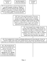
- a terminal device includes a receiver, a transmitter, a processor, and a memory; the receiver, the transmitter, and the memory are separately connected to the processor; and the processor is configured to: obtain, based on auxiliary data configured by a network device, identifiers of at least two antenna elements and attribute information of a reference signal corresponding to each of the at least two antenna elements; receive at least two reference signals based on the attribute information, where the at least two reference signals are sent by corresponding antenna elements of the at least two antenna elements, respectively; obtain positioning information by measuring the at least two reference signals; and send, to the network device, the positioning information and identification information of antenna elements corresponding to the positioning information.
- the terminal device can identify which antenna element a received reference signal comes from. Therefore, an improved distributed antenna system can implement terminal device positioning, and improve indoor positioning accuracy.
- the positioning information includes a time difference of arrival
- the processor is configured to obtain a time difference of arrival between reference signals sent by each two antenna elements, of the at least two reference signals. Because the terminal device can identify an antenna element that sends each reference signal, the observed time difference of arrival positioning method can be applied to a distributed positioning system, to implement indoor positioning.
- the processor is configured to receive the auxiliary data sent by the network device. Because the reference signals sent by the antenna elements can be received and distinguished between based on the auxiliary data, indoor positioning can be implemented.
- a positioning information sending apparatus includes: an obtaining module, configured to obtain, based on auxiliary data configured by a network device, identifiers of at least two antenna elements and attribute information of a reference signal corresponding to each of the at least two antenna elements; a receiving module, configured to receive at least two reference signals based on the attribute information, where the at least two reference signals are sent by corresponding antenna elements of the at least two antenna elements, respectively; a measurement module, configured to obtain positioning information by measuring the at least two reference signals; and a sending module, configured to send, to the network device, the positioning information and identification information of antenna elements corresponding to the positioning information.
- a terminal device can identify which antenna element a received reference signal comes from. Therefore, an improved distributed antenna system can implement terminal device positioning, and improve indoor positioning accuracy.
- the positioning information includes a time difference of arrival
- the measurement module is configured to obtain a time difference of arrival between reference signals sent by each two antenna elements, of the at least two reference signals. Because the terminal device can identify an antenna element that sends each reference signal, the observed time difference of arrival positioning method can be applied to a distributed positioning system, to implement indoor positioning.
- the receiving module is further configured to receive the auxiliary data sent by the network device. Because the reference signals sent by the antenna elements can be received and distinguished between based on the auxiliary data, indoor positioning can be implemented.
- a network device includes a receiver, a transmitter, a processor, and a memory, the receiver, the transmitter, and the memory are separately connected to the processor, and the processor is configured to generate a specified quantity of reference signals, where each reference signal has different attribute information; and the network device further includes a frequency conversion module and a local oscillator module, where the local oscillator module is connected to the frequency conversion module, and the frequency conversion module is connected to the transmitter; and the frequency conversion module is configured to respectively convert, based on different local frequencies generated by the local oscillator module, carrier frequencies of the generated specified quantity of reference signals to different carrier frequencies, where the specified quantity of reference signals are sent through the transmitter to a specified quantity of antenna elements.
- the network device uses a frequency domain separation approach to allocate reference signals having different attribute information to different antenna elements, so that a terminal device can identify which antenna element a received reference signal comes from. Therefore, an improved distributed antenna system can implement terminal device positioning, and improve indoor positioning accuracy.
- a network device includes a receiver, a transmitter, a processor, and a memory, the receiver, the transmitter, and the memory are separately connected to the processor, and the processor is configured to: obtain a specified quantity of scrambling codes, and generate a specified quantity of reference signals, where each reference signal is scrambled by a different scrambling code, and each reference signal has different attribute information; and the network device further includes a scrambling module and a scrambling code generation module, where the scrambling module is connected to the scrambling code generation module, and the scrambling module is connected to the transmitter; the scrambling code generation module is configured to generate a specified quantity of scrambling codes; and the scrambling module is configured to generate a specified quantity of reference signals, where each reference signal is scrambled by a different scrambling code, and the specified quantity of reference signals are sent through the transmitter to a specified quantity of antenna elements.
- the network device uses a code domain separation approach to allocate different reference signals to different antenna elements
- a positioning system including a network device and a plurality of antenna elements; the network device is configured to: generate a plurality of reference signals, respectively convert carrier frequencies of the plurality of reference signals to different carrier frequencies, and send the plurality of reference signals to the plurality of antenna elements, where each reference signal has different attribute information; and each of the plurality of antenna elements is configured to: perform, after receiving the plurality of reference signals sent by the network device, frequency mixing processing on a reference signal carried on a carrier frequency corresponding to the antenna element, to obtain a specified reference signal; and send the specified reference signal to a terminal device.
- Reference signals obtained by different antenna elements are different, so that the terminal device can identify which antenna element a received reference signal comes from. Therefore, an improved distributed antenna system can implement terminal device positioning, and improve indoor positioning accuracy.
- each antenna element is further configured to: perform, after obtaining the specified reference signal, polarization processing on the specified reference signal by using a specified polarization type; and send the polarized specified reference signal to the terminal device.
- Different antenna elements may polarize reference signals by using different polarization types. Therefore, the terminal device can recognize, based on a polarization type of a reference signal, an antenna element that sends the reference signal. In this way, positioning accuracy is improved.
- a positioning system including a network device and a plurality of antenna elements; the network device is configured to: obtain a specified quantity of scrambling codes, and generate a plurality of reference signals, where each reference signal is scrambled by a different scrambling code, and each reference signal has different attribute information; and send the plurality of reference signals to the plurality of antenna elements; and each of the plurality of antenna elements is configured to: perform, after receiving the plurality of reference signals, descrambling processing on a reference signal corresponding to a scrambling code of the antenna element, to obtain a specified reference signal; and send the specified reference signal to a terminal device.
- Reference signals obtained by different antenna elements are different, so that the terminal device can identify which antenna element a received positioning signal comes from. Therefore, an improved distributed antenna system can implement terminal device positioning, and improve indoor positioning accuracy.
- each antenna element is further configured to: perform, after obtaining the specified reference signal, polarization processing on the specified reference signal by using a specified polarization type; and send the polarized specified reference signal to the terminal device.
- Different antenna elements may polarize reference signals by using different polarization types. Therefore, the terminal device can recognize, based on a polarization type of a reference signal, an antenna element that sends the reference signal. In this way, positioning accuracy is improved.
- a positioning system including a network device and a plurality of antenna elements; the network device is configured to: generate a reference signal, and send the reference signal to the plurality of antenna elements; and each of the plurality of antenna elements is configured to: perform, after receiving the reference signal, polarization processing on the reference signal by using a specified polarization type, to obtain a plurality of reference signals of different polarization types; and send the plurality of reference signals to a terminal device.
- Different antenna elements may use different polarization types to polarize the reference signal, so that the terminal device can tell, based on a polarization type, which antenna element a received reference signal comes from. Therefore, an improved distributed antenna system can implement terminal device positioning, and improve indoor positioning accuracy.
- a positioning information sending method includes: obtaining, based on auxiliary data configured by a network device, identifiers of at least two antenna elements and attribute information of a reference signal corresponding to each of the at least two antenna elements; receiving at least two reference signals based on the attribute information, where the at least two reference signals are sent by corresponding antenna elements of the at least two antenna elements, respectively; obtaining positioning information by measuring the at least two reference signals; and sending, to the network device, the positioning information and identification information of antenna elements corresponding to the positioning information.
- a terminal device can identify which antenna element a received reference signal comes from. Therefore, an improved distributed antenna system can implement terminal device positioning, and improve indoor positioning accuracy.
- the positioning information includes a time difference of arrival
- the method further includes: obtaining a time difference of arrival between reference signals sent by each two antenna elements, of the at least two reference signals. Because the terminal device can identify an antenna element that sends each reference signal, the observed time difference of arrival positioning method can be applied to a distributed positioning system, to implement indoor positioning.
- the method further includes: receiving the auxiliary data sent by the network device. Because the reference signals sent by the antenna elements can be received and distinguished between based on the auxiliary data, indoor positioning can be implemented.
- a reference signal sending method includes: generating a specified quantity of reference signals, where each reference signal has different attribute information; and respectively converting carrier frequencies of the generated specified quantity of reference signals to different carrier frequencies based on different local frequencies, and sending the specified quantity of reference signals to a specified quantity of antenna elements.
- a network device uses a frequency domain separation approach to allocate reference signals having different attribute information to different antenna elements, so that a terminal device can identify which antenna element a received reference signal comes from. Therefore, an improved distributed antenna system can implement terminal device positioning, and improve indoor positioning accuracy.
- frequency spectra of the different carrier frequencies do not interfere with each other, so that the reference signals carried on the different carrier frequencies are separated from each other and do not interfere with each other.
- a reference signal sending method includes: performing, after receiving a plurality of reference signals sent by a network device, frequency mixing processing on a reference signal carried on a corresponding carrier frequency, to obtain a specified reference signal; and sending the specified reference signal to a terminal device.
- An antenna element can obtain a reference signal on a carrier frequency corresponding to the antenna element, so that the terminal device can identify which antenna element a received reference signal comes from. Therefore, an improved distributed antenna system can implement terminal device positioning, and improve indoor positioning accuracy.
- the method further includes: performing polarization processing on the specified reference signal by using a specified polarization type; and sending the polarized specified reference signal to the terminal device.
- Different antenna elements may polarize reference signals by using different polarization types. Therefore, the terminal device can recognize, based on a polarization type of a reference signal, an antenna element that sends the reference signal. In this way, positioning accuracy is improved.
- a reference signal sending method includes: obtaining a specified quantity of scrambling codes, and generating a plurality of reference signals, where each reference signal is scrambled by a different scrambling code, and each reference signal has different attribute information; and sending the plurality of reference signals to a plurality of antenna elements, where each of the specified quantity of antenna elements obtains a reference signal carried on a carrier frequency corresponding to the antenna element.
- a network device uses a code domain separation approach to allocate reference signals having different attribute information to different antenna elements, so that a terminal device can identify which antenna element a received reference signal comes from. Therefore, an improved distributed antenna system can implement terminal device positioning, and improve indoor positioning accuracy.
- the different scrambling codes are orthogonal to each other, so that reference signals scrambled by different scrambling codes do not interfere with each other.
- a reference signal sending method includes: performing, after receiving a plurality of reference signals, descrambling processing on a reference signal corresponding to a scrambling code, to obtain a specified reference signal, and sending the specified reference signal to a terminal device.
- Reference signals obtained by different antenna elements are different, so that the terminal device can identify which antenna element a received positioning signal comes from. Therefore, an improved distributed antenna system can implement terminal device positioning, and improve indoor positioning accuracy.
- the method further includes: performing polarization processing on the specified reference signal by using a specified polarization type; and sending the polarized specified reference signal to the terminal device.
- Different antenna elements may polarize reference signals by using different polarization types. Therefore, the terminal device can recognize, based on a polarization type of a reference signal, an antenna element that sends the reference signal. In this way, positioning accuracy is improved.
- a positioning information sending method includes: obtaining, based on auxiliary data configured by a network device, identifiers of at least two antenna elements and a polarization type of a reference signal corresponding to each of the at least two antenna elements; receiving at least two reference signals based on the polarization types, where the at least two reference signals are sent by corresponding antenna elements of the at least two antenna elements, respectively; obtaining positioning information by measuring the at least two reference signals; and sending, to the network device, the positioning information and identification information of antenna elements corresponding to the positioning information.
- a terminal device can identify which antenna element a received reference signal comes from. Therefore, an improved distributed antenna system can implement terminal device positioning, and improve indoor positioning accuracy.
- a reference signal sending method includes: performing, after receiving a reference signal, polarization processing on a reference signal by using a specified polarization type, and sending the polarized reference signal to a terminal device.
- Different antenna elements may polarize reference signals by using different polarization types. Therefore, the terminal device can recognize, based on a polarization type of a reference signal, an antenna element that sends the reference signal. In this way, positioning accuracy is improved.
- an antenna element configured to: generate a specified local frequency; and perform, based on the specified local frequency after receiving a specified quantity of reference signals by using the divider, frequency mixing processing on a reference signal carried on a carrier frequency corresponding to the antenna element, to obtain a specified reference signal, where the specified reference signal is sent by the antenna to a terminal device.
- An antenna element can obtain a reference signal on a carrier frequency corresponding to the antenna element, so that the terminal device can identify which antenna element a received reference signal comes from. Therefore, an improved distributed antenna system can implement terminal device positioning, and improve indoor positioning accuracy.
- an antenna element includes a divider, a descrambling module, and an antenna; and the descrambling module is configured to: generate a specified scrambling code, and perform, based on the specified scrambling code after receiving a specified quantity of reference signals transmitted by the divider, descrambling processing on a reference signal corresponding to a scrambling code of the antenna element, to obtain a specified reference signal, where the specified reference signal is sent by the antenna to a terminal device.
- Reference signals obtained by different antenna elements are different, so that the terminal device can identify which antenna element a received reference signal comes from. Therefore, an improved distributed antenna system can implement terminal device positioning, and improve indoor positioning accuracy.
- an antenna element includes a polarization module and an antenna; and the polarization module is configured to perform, after receiving a reference signal, polarization processing on the reference signal by using a specified polarization type, to obtain a specified reference signal, where the specified reference signal is sent by the antenna to a terminal device.
- the antenna element includes a polarization module and an antenna; and the polarization module is configured to perform, after receiving a reference signal, polarization processing on the reference signal by using a specified polarization type, to obtain a specified reference signal, where the specified reference signal is sent by the antenna to a terminal device.
- Different antenna elements may use different polarization types to polarize the reference signal, so that the terminal device can tell, based on a polarization type, which antenna element a received reference signal comes from. Therefore, an improved distributed antenna system can implement terminal device positioning, and improve indoor positioning accuracy.
- FIG. 1 is a structural diagram of a distributed antenna system, including a network device and a plurality of antenna elements.
- the plurality of antenna elements are located indoors and are connected to the network device.
- the network device (for example, a base station in FIG. 1 ) in the existing distributed antenna system can send only a same reference signal to all antenna elements connected to the network device.
- Each antenna element sends a received reference signal to a terminal device. Because all the reference signals are the same, after receiving the reference signals indoors, the terminal device cannot distinguish between the antenna elements that send the reference signals.
- the existing distributed antenna system cannot be used to implement indoor positioning.
- the existing distributed antenna system is improved, so that an improved distributed antenna system can implement indoor positioning, and improve indoor positioning accuracy of a mobile network.
- FIG. 2 is a structural diagram of a positioning system according to an embodiment of the present invention.
- the positioning system is a distributed antenna system.
- a frequency domain separation method is used to improve an existing distributed antenna system.
- the distributed antenna system includes a network device and a specified quantity of antenna elements. A frequency conversion module and a local oscillator module are added at a port at which the network device sends signals to the antenna elements.
- the local oscillator module is configured to generate different local frequencies.
- the network device is configured to: generate a specified quantity of reference signals having different attribute information, and respectively convert carrier frequencies of the specified quantity of reference signals to different carrier frequencies based on different local frequencies, which means separating different reference signals in frequency domain; and then send the specified quantity of reference signals in different frequency domains to the specified quantity of antenna elements.
- Each antenna element includes a divider, a frequency mixing module, an antenna, and the like, or includes parts having same functions.
- the frequency mixing module may generate a specified local frequency, and is configured to: perform frequency mixing processing on a reference signal on a carrier frequency corresponding to the antenna element, and send an obtained specified reference signal to a terminal device. Finally, different antenna elements send different reference signals to the terminal device.
- a correspondence between an identifier of each antenna element and attribute information of each reference signal is stored in the network device.
- connections between the network device and the specified quantity of antenna elements may be physical connections, for example, coaxial cable or optical cable connections, or may be wireless connections. This is not specifically limited in this embodiment of the present invention.
- the distributed antenna system shown in FIG. 2 further includes couplers. The couplers and the dividers of the antenna elements are configured to make a signal transmit power allocated to all antenna elements as uniformly as possible, so that transmit powers of all the antenna elements are essentially the same.
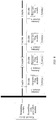
- FIG. 3 is a flowchart of a positioning method provided with reference to the positioning system in FIG. 2 according to an embodiment of the present invention. Included interacting entities are a network device, a specified quantity of antenna elements, and a terminal device. Referring to FIG. 3 , a process of the method provided in this embodiment of the present invention includes the following steps.
- the network device respectively converts carrier frequencies of a specified quantity of reference signals to different carrier frequencies after generating the specified quantity of reference signals, and sends the specified quantity of reference signals to the specified quantity of antenna elements.
- the network device is connected to the specified quantity of antenna elements to form a distributed antenna system.
- the network device is a physical or logical entity in the distributed antenna system that is configured to generate a reference signal and process the reference signal and that has a function of positioning a terminal device.
- a specific form of the network device is not limited in this embodiment of the present invention.
- the network device generates the specified quantity of reference signals. Each reference signal has different attribute information.
- the attribute information includes a pseudorandom sequence, a resource mapping manner, or the like for generating the reference signal, so that the terminal device can restore the corresponding reference signal based on the attribute information.
- the frequencies of the specified quantity of reference signals are converted to the different carrier frequencies, and the specified quantity of reference signals are sent to the specified quantity of antenna elements.
- a specific implementation process is as follows:
- the network device first generates the specified quantity of reference signals. All the reference signals have a same fixed initial carrier frequency. After the specified quantity of reference signals having the same fixed carrier frequency are transferred to a frequency conversion module, the frequency conversion module converts, based on different local frequencies generated by a local oscillator module, frequencies of the generated specified quantity of reference signals to the different carrier frequencies to obtain the specified quantity of reference signals carried on the different carrier frequencies, and the specified quantity of reference signals carried on the different carrier frequencies are sent to the specified quantity of antenna elements.
- the network device first generates three reference signals S1, S2, and S3.
- S1, S2, and S3 have different identification information and a same fixed initial carrier frequency F1.
- the local oscillator module generates two local frequencies F4 and F5.
- the frequency conversion module may be used to respectively convert carrier frequencies of the different reference signals to different carrier frequencies.
- the frequency conversion module mixes the initial carrier frequency F1 of S2 and the local frequency F4, so that a frequency of the reference signal S2 is converted to the carrier frequency F2.
- the frequency conversion module mixes the initial carrier frequency F1 of S3 and the local frequency F5, so that a frequency of the reference signal S3 is converted to the carrier frequency F3.
- a carrier frequency of the reference signal S1 is F1
- a carrier frequency of the reference signal S2 is F2
- a carrier frequency of the reference signal S3 is F3. In this way, frequencies of different reference signals are converted to different carrier frequencies.
- Frequency spectra of the different carrier frequencies do not interfere with each other.
- a quantity of the reference signals generated by the network device is not specifically limited in this embodiment of the present invention.
- a quantity of the local frequencies generated by the local oscillator module may be the same as the specified quantity of the reference signals generated by the network device, or may be the specified quantity minus 1. This is not specifically limited in this embodiment of the present invention.
- the quantity of the local frequencies is the specified quantity minus 1
- no frequency conversion processing is performed on a carrier frequency of one of the specified quantity of reference signals.
- the carrier frequency is always a fixed carrier frequency.
- frequency conversion processing is performed on a carrier frequency of each of the specified quantity of reference signals.
- Each of the specified quantity of antenna elements performs, after receiving the specified quantity of reference signals, frequency mixing processing on a reference signal carried on a carrier frequency corresponding to the antenna element, to obtain a specified reference signal; and sends the specified reference signal to the terminal device.
- the frequency mixing module is further configured to restore a carrier frequency of a reference signal to a fixed carrier frequency.
- Each of the specified quantity of antenna elements performs, after receiving the specified quantity of reference signals, frequency mixing processing on a reference signal carried on a carrier frequency corresponding to the antenna element, to obtain the specified reference signal.
- a frequency mixing module in each antenna element After receiving the specified quantity of reference signals by using a divider, a frequency mixing module in each antenna element performs, based on a specified local frequency, frequency mixing processing on a reference signal carried on a carrier frequency corresponding to the antenna element, to obtain the specified reference signal.
- the carrier frequency corresponding to the antenna element is a carrier frequency that can be mixed with the local frequency to obtain the fixed carrier frequency.
- the system includes three antenna elements A1, A2, and A3.
- a frequency mixing module in the antenna element A2 generates a local frequency F4, and a frequency mixing module in the antenna element A3 generates a local frequency F5.
- the antenna element A2 mixes the carrier frequency F2 and the local frequency F4, to obtain the reference signal S2 whose carrier frequency is the fixed carrier frequency F1;
- the antenna element A3 performs mixes the carrier frequency F3 and the local frequency F5, to obtain the reference signal S3 whose carrier frequency is the fixed carrier frequency F1; and after the antenna element A1 receives the specified quantity of reference signals, a frequency mixing module in the antenna element A1 directly obtains, through filtering, the reference signal S1 whose carrier frequency is the fixed carrier frequency F1.
- each antenna element obtains a specified reference signal having different identification information, and sends the specified reference signal to the terminal device.
- the antenna element A1 sends the reference signal S1 to the terminal device
- the antenna element A2 sends the reference signal S2 to the terminal device
- the antenna element A3 sends the reference signal S3 to the terminal device.
- local frequencies generated by frequency mixing modules in all the antenna elements shall be equal to local frequencies for performing frequency conversion processing on all reference signals by the network device correspondingly in a one-to-one manner.
- Each antenna element can obtain a different specified reference signal only in this way.
- each antenna element may further include a polarization module.
- the polarization module is configured to perform polarization processing on the specified reference signal, and send the polarized specified reference signal to the terminal device.
- Polarization types indicated by polarization modules in different antenna elements are different.
- the polarization types may be horizontal polarization, perpendicular polarization, circular polarization, elliptical polarization, polarization with a specified angle, and the like. This is not limited in this embodiment of the present invention.
- the terminal device obtains, based on auxiliary data configured by the network device, identifiers of at least two antenna elements and attribute information of a reference signal corresponding to each of the at least two antenna elements, and receives at least two reference signals based on the attribute information.
- a terminal device positioning process may be initiated by a terminal device side, or may be initiated by a network device side. This is not limited in this embodiment of the present invention.
- the network device After receiving a positioning request sent by the terminal device, the network device sends positioning capability request signaling to the terminal device. After receiving the signaling, the terminal device replies with corresponding positioning capability information including an available hardware resource, a positioning computation capability, signal quality, or the like. Then, the terminal device sends an auxiliary data request to the network device. The network device returns configured auxiliary data after receiving the auxiliary data request.
- the auxiliary data includes the identifiers of the at least two antenna elements and the attribute information of the reference signal corresponding to each of the at least two antenna elements.
- the auxiliary data may further include a polarization type of the reference signal corresponding to each of the at least two antenna elements.
- the terminal device restores the at least two reference signals based on the attribute information of each reference signal. Then, the terminal device receives, from the plurality of reference signals sent by the plurality of antenna elements, a reference signal that is the same as each restored reference signal, and obtains identification information of the corresponding antenna element.
- the identification information of the antenna element may be a name, a device number, an ID (Identifier, identifier) number, a physical address, an IP (Internet Protocol, Internet Protocol) address, or the like of the antenna element. This is not limited in this embodiment of the present invention.
- an antenna element identifier is any piece of the foregoing antenna element identification information. Distinguishing between an antenna element identifier and antenna element identification information is intended to describe that one antenna element may have different unique identifiers. In a process in which the terminal device communicates with the network device, different identifiers of one antenna element may be used for communication.
- the auxiliary data sent by the network device to the terminal device may further include a reference signal receiving time window, so that after receiving the reference signal receiving time window, the terminal device receives, based on the attribute information, only a reference signal within the reference signal receiving time window. In this way, electricity consumption of the terminal device can be reduced.
- the auxiliary data may further include the identifiers of the at least two antenna elements and a polarization type of the reference signal corresponding to each of the at least two antenna elements.
- the terminal device receives the at least two reference signals based on the polarization types.
- the terminal device obtains positioning information by measuring the at least two reference signals, and sends, to the network device, the positioning information and identification information of antenna elements corresponding to the positioning information.
- the auxiliary data sent by the network device may further include a positioning method that needs to be used.
- the positioning method may be a time difference of arrival measurement positioning method, an angle detection positioning method, or a field strength detection positioning method. This is not limited in this embodiment of the present invention.
- the following uses the time difference of arrival measurement positioning method as an example to describe a process in which the terminal device obtains positioning information by measuring the at least two reference signals.
- the terminal device obtains, after obtaining the at least two reference signals and the identification information of the antenna element corresponding to each of the reference signals, a time difference of arrival between reference signals sent by each two antenna elements, of the at least two reference signals, records identification information of the two antenna elements corresponding to the time difference of arrival, and generates the positioning information.
- the positioning information includes the time difference of arrival.
- the positioning information and the identification information of the antenna elements corresponding to the positioning information are sent to the network device.
- the identification information of the antenna elements corresponding to the positioning information is identification information of two antenna elements corresponding to each time difference of arrival.
- the auxiliary data sent by the network device to the terminal device may further include a comparison reference signal.
- the terminal device records a first time of arrival at which a reference signal having same identification information as the comparison reference signal is received, and after receiving any reference signal based on the attribute information, calculates a second time of arrival of the any reference signal, and determines a time difference between the first time of arrival and the second time of arrival as a time difference of arrival of the any reference signal.
- the network device positions the terminal device based on the received positioning information and the identification information of the antenna elements corresponding to the positioning information.
- the network device is capable of positioning the terminal device based on the received positioning information and the identification information of the antenna elements corresponding to the positioning information.
- the time difference of arrival measurement positioning method is used as an example.
- the network device stores a correspondence between the identification information of each antenna element connected to the network device and a physical location of the antenna element. After receiving the positioning information and the identification information of the antenna elements corresponding to the positioning information that are sent by the terminal device, the network device obtains, based on the identification information of the antenna elements, physical locations of the antenna elements corresponding to the identification information of the antenna elements. Then, the location of the terminal device is obtained based on each time difference of arrival and physical locations of corresponding antenna elements.
- the terminal device when the terminal device is positioned by using the time difference of arrival measurement positioning method, the terminal device sends, to the network device, at least two time differences of arrival and identification information of antenna elements corresponding to each time difference of arrival, so that the network device may obtain at least two hyperbolic positioning areas based on each time of arrival and physical locations of antenna elements corresponding to the time of arrival, and calculate an intersection location of the at least two hyperbolic positioning areas to determine the location of the terminal device. Then, positioning of the terminal device is completed.
- the network device converts the frequencies of the specified quantity of reference signals to the different carrier frequencies after generating the specified quantity of reference signals, and sends the specified quantity of reference signals to the specified quantity of antenna elements; each of the specified quantity of antenna elements performs, after receiving the specified quantity of reference signals, frequency mixing processing on the reference signal carried on the carrier frequency corresponding to the antenna element, to obtain the specified reference signal; and sends the specified reference signal to the terminal device; and the terminal device obtains, based on the auxiliary data configured by the network device, the identifiers of the at least two antenna elements and the attribute information of the reference signal corresponding to each of the at least two antenna elements, receives the at least two reference signals based on the attribute information, obtains the positioning information by measuring the at least two reference signals, and sends, to the network device, the positioning information and the identification information of the antenna elements corresponding to the positioning information.
- Reference signals obtained by different antenna elements are different, so that the terminal device can identify which antenna element a received reference signal comes from. Therefore,
- FIG. 4 is a structural diagram of a positioning system according to an embodiment of the present invention.
- the positioning system is a distributed antenna system.
- a code domain separation method is used to improve an existing distributed antenna system.
- the distributed antenna system includes a network device and a specified quantity of antenna elements connected to the network device. A scrambling module and a scrambling code generation module are added at a port at which the network device sends signals to the antenna elements.
- the scrambling code generation module is configured to generate different scrambling codes.
- the network device is configured to generate a specified quantity of reference signals based on the different scrambling codes. Each reference signal is scrambled by a different scrambling code. To be specific, different reference signals are separated into different code domains. Then the specified quantity of reference signals in different code domains are sent to the specified quantity of antenna elements.
- Each antenna element includes a divider, a descrambling module, an antenna, and the like, or includes parts having same functions.
- the descrambling module may generate a specified scrambling code, and is configured to: descramble a scrambling code of a reference signal corresponding to an antenna element, and send the obtained specified reference signal to the terminal device by using the antenna. Finally, different antenna elements send different reference signals to the terminal device. In addition, a correspondence between an identifier of each antenna element and attribute information of each reference signal is stored in the network device.
- connections between the network device and the specified quantity of antenna elements may be physical connections, for example, coaxial cable or optical cable connections, or may be wireless connections. This is not limited in this embodiment of the present invention.
- the distributed antenna system shown in FIG. 4 further includes couplers. The couplers and the dividers are configured to make a signal transmit power allocated to all antenna elements as uniformly as possible, so that transmit powers of all the antenna elements are essentially the same.
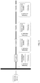
- FIG. 5 is a flowchart of a positioning method provided with reference to the positioning system in FIG. 4 according to an embodiment of the present invention. Included interacting entities are a network device, a specified quantity of antenna elements, and a terminal device. Referring to FIG. 5 , a process of the method provided in this embodiment of the present invention includes the following steps.
- the network device generates a specified quantity of reference signals after obtaining a specified quantity of scrambling codes, and sends the specified quantity of reference signals to the specified quantity of antenna elements.
- the network device is connected to the specified quantity of antenna elements to form a distributed antenna system.
- the network device is a physical or logical entity in the distributed antenna system that is configured to generate a reference signal and process the reference signal and that has a function of positioning a terminal device.
- a specific form of the network device is not limited in this embodiment of the present invention.
- the network device After obtaining the specified quantity of scrambling codes, the network device generates the specified quantity of reference signals. Each reference signal is scrambled by a different scrambling code. Each reference signal has different attribute information.
- the attribute information includes a pseudorandom sequence, a resource mapping manner, or the like for generating the reference signal, so that the terminal device can restore the corresponding reference signal based on the attribute information.
- the specified quantity of reference signals are sent to the specified quantity of antenna elements.
- a specific implementation process is as follows:
- the network device first generates a specified quantity of initial reference signals having different signal identifiers.
- the specified quantity of initial reference signals have different identification information.
- Each initial reference signal is included in a fixed codeword.
- the scrambling module scrambles, based on different scrambling codes generated by a scrambling code generation module, the specified quantity of initial reference signals into different codewords, to obtain the specified quantity of reference signals, and sends the specified quantity of reference signals to the specified quantity of antenna elements.
- the network device first generates three initial reference signals S1, S2, and S3.
- S1, S2, and S3 have different identification information, and all are included in a fixed codeword C1.
- the scrambling code generation module generates two scrambling codes C4 and C5.
- the scrambling module may be used to scramble different initial reference signals into different codewords.
- the scrambling module scrambles the fixed codeword C1 including S2 by using the scrambling code C4 to obtain a codeword C2 including S2, and the scrambling module scrambles the fixed codeword C1 including S3 by using the scrambling code C5 to obtain a codeword C3 including S3.
- a carrier frequency of the reference signal S1 is C1
- a carrier frequency of the reference signal S2 is C2
- a carrier frequency of the reference signal S3 is C3. In this way, frequencies of different reference signals are converted to different carrier frequencies.
- a quantity of the initial reference signals generated by the network device is not specifically limited in this embodiment of the present invention.
- a quantity of the scrambling codes generated by the scrambling code generation module may be the same as the specified quantity of the initial reference signals generated by the network device, or may be the specified quantity minus 1. This is not limited in this embodiment of the present invention.
- the quantity of the scrambling codes is the specified quantity minus 1
- no scrambling processing is performed by the scrambling code module on one of the specified quantity of initial reference signals.
- the quantity of the scrambling codes is the specified quantity, scrambling processing is performed by the scrambling code module on each of the specified quantity of initial reference signals.
- the network device directly obtains a specified quantity of scrambling codes, generates, based on the specified quantity of scrambling codes, a specified quantity of reference signals having different codewords, and then sends the specified quantity of reference signals to the specified quantity of antenna elements.
- Each of the specified quantity of antenna elements performs, after receiving the specified quantity of reference signals, descrambling processing on a reference signal corresponding to a scrambling code of the antenna element, to obtain a specified reference signal; and sends the specified reference signal to the terminal device.
- each of the specified quantity of antenna elements performs, after receiving the specified quantity of reference signals, descrambling processing on a reference signal corresponding to a scrambling code of the antenna element, to obtain the specified reference signal.
- a detailed process is as follows:
- a descrambling module in each antenna element performs, based on the specified scrambling code after receiving the specified quantity of reference signals by using the divider, descrambling processing on the reference signal corresponding to the scrambling code of the antenna element, to obtain the specified reference signal whose codeword is a fixed codeword.
- the reference signal corresponding to the scrambling code of the antenna element is a reference signal obtained after the network device scrambles any initial reference signal by using a scrambling code that is the same as the specified scrambling code.
- a descrambling module in the antenna element A2 generates a scrambling code C4, and a descrambling module in the antenna element A3 generates a scrambling code C5.
- the antenna element A2 descrambles the codeword C2 by using the scrambling code C4, to obtain the reference signal S2 whose codeword is a fixed codeword C1;
- the antenna element A3 descrambles the codeword C3 by using the scrambling code C5, to obtain the reference signal S3 whose codeword is the fixed codeword C1; and after the antenna element A1 receives the specified quantity of reference signals, a descrambling module included in the antenna element A1 directly obtains the reference signal S1 whose codeword is the fixed codeword C1.
- each antenna element obtains a specified reference signal having different identification information, and sends the specified reference signal to the terminal device.
- the antenna element A1 sends the reference signal S1 to the terminal device
- the antenna element A2 sends the reference signal S2 to the terminal device
- the antenna element A3 sends the reference signal S3 to the terminal device.
- the scrambling codes generated by descrambling modules in all the antenna elements shall be equal to scrambling codes for performing scrambling processing on all reference signals by the network device correspondingly in a one-to-one manner. Each antenna element can obtain a different specified reference signal only in this way.
- each antenna element may further include a polarization module.
- the polarization module is configured to perform polarization processing on the specified reference signal, and send the polarized specified reference signal to the terminal device.
- Polarization types indicated by polarization modules in different antenna elements are different.
- the polarization types may be horizontal polarization, perpendicular polarization, circular polarization, elliptical polarization, polarization with a specified angle, and the like. This is not limited in this embodiment of the present invention.
- the terminal device obtains, based on auxiliary data configured by the network device, identifiers of at least two antenna elements and attribute information of a reference signal corresponding to each of the at least two antenna elements, and receives at least two reference signals based on the attribute information.
- this step is the same as the process in step 303 in which the terminal device obtains, based on auxiliary data configured by the network device, identifiers of at least two antenna elements and attribute information of a reference signal corresponding to each of the at least two antenna elements, and receives at least two reference signals based on the attribute information. No details are repeated herein.
- the terminal device obtains positioning information by measuring the at least two reference signals, and sends, to the network device, the positioning information and identification information of antenna elements corresponding to the positioning information.
- this step is the same as the process in step 304 in which the terminal device obtains positioning information by measuring the at least two reference signals, and sends, to the network device, the positioning information and identification information of antenna elements corresponding to the positioning information. No details are repeated herein.
- the network device positions the terminal device based on the received positioning information and the identification information of the antenna elements corresponding to the positioning information.
- this step is the same as the process in step 305 in which the network device positions the terminal device based on received positioning data. No details are repeated herein.
- the network device generates the specified quantity of reference signals based on the specified quantity of scrambling codes, where each reference signal is scrambled by a different scrambling code; and then sends the specified quantity of reference signals to the specified quantity of antenna elements; each of the specified quantity of antenna elements performs, after receiving the specified quantity of reference signals, descrambling processing on the reference signal corresponding to the scrambling code of the antenna element, to obtain the specified reference signal; and sends the specified reference signal to the terminal device; and the terminal device obtains, based on the auxiliary data configured by the network device, the identifiers of the at least two antenna elements and the attribute information of the reference signal corresponding to each of the at least two antenna elements, receives the at least two reference signals based on the attribute information, obtains the positioning information by measuring the at least two reference signals, and sends, to the network device, the positioning information and the identification information of the antenna elements corresponding to the positioning information.
- Reference signals obtained by different antenna elements are different, so that the terminal
- FIG. 6 is a structural diagram of a positioning system according to an embodiment of the present invention.
- the positioning system is a distributed antenna system.
- a polarization separation method is used to improve an existing distributed antenna system.
- the distributed antenna system includes a network device and a specified quantity of antenna elements. The network device is configured to: generate a reference signal, and send the reference signal to the specified quantity of antenna elements.
- Each antenna element includes a polarization module, an antenna, and the like, or includes parts having same functions.
- the polarization module is configured to polarize the reference signal by using a specified polarization type, to obtain a specified reference signal.
- Polarization types indicated by polarization modules in different antenna elements are different.
- the polarization types may be horizontal polarization, perpendicular polarization, circular polarization, elliptical polarization, polarization with a specified angle, and the like. This is not limited in this embodiment of the present invention.
- the obtained specified reference signal is sent to the terminal device by using the antenna.
- different antenna elements send reference signals of different polarization types to the terminal device.
- a correspondence between an identifier of each antenna element and a polarization type of a reference signal corresponding to the antenna element is stored in the network device.
- connections between the network device and the specified quantity of antenna elements may be physical connections, for example, coaxial cable or optical cable connections, or may be wireless connections. This is not limited in this embodiment of the present invention.
- the distributed antenna system shown in FIG. 6 further includes couplers that are configured to make a signal transmit power allocated to all antenna elements as uniformly as possible, so that transmit powers of all the antenna elements are essentially the same.
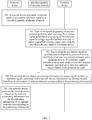
- FIG. 7 is a flowchart of a positioning method provided with reference to the positioning system in FIG. 6 according to an embodiment of the present invention. Included interacting entities are a network device, a specified quantity of antenna elements, and a terminal device. Referring to FIG. 7 , a process of the method provided in this embodiment of the present invention includes the following steps.
- the network device generates a reference signal, and sends the reference signal to the specified quantity of antenna elements.
- the network device is connected to the specified quantity of antenna elements to form a distributed antenna system.
- the network device is a physical or logical entity in the distributed antenna system that is configured to generate a reference signal and process the reference signal and that has a function of positioning a terminal device.
- a specific form of the network device is not limited in this embodiment of the present invention.
- Each of the specified quantity of antenna elements performs, after receiving the reference signal, polarization processing on the reference signal by using a specified polarization type, to obtain a specified reference signal; and sends the specified reference signal to the terminal device.
- polarization modules in different antenna elements in the system indicate different polarization types.
- the polarization types may be horizontal polarization, perpendicular polarization, circular polarization, elliptical polarization, polarization with a specified angle, and the like. This is not limited in this embodiment of the present invention.
- Each antenna element performs, after receiving the reference signal, polarization processing on the specified signal by using the polarization module and a specified polarization type, to obtain the specified reference signal; and sends the specified reference signal to the terminal device. After the specified quantity of antenna elements perform polarization processing on the reference signal, specified reference signals of different polarization types are obtained.
- the system includes three antenna elements A1, A2, and A3.
- a polarization type corresponding to a polarization module P1 in the antenna element A1 is horizontal polarization
- a polarization type corresponding to a polarization module P2 in the antenna element A2 is circular polarization
- a polarization type corresponding to a polarization module P3 in the antenna element A3 is perpendicular polarization.
- the antenna element A1 horizontally polarizes, after receiving the reference signal, the reference signal by using the polarization module P1, and sends the horizontally polarized reference signal to the terminal device.
- the antenna element A2 circularly polarizes, after receiving the reference signal, the reference signal by using the polarization module P2, and sends the circularly polarized reference signal to the terminal device.
- the antenna element A3 perpendicularly polarizes, after receiving the reference signal, the reference signal by using the polarization module P3, and sends the perpendicularly polarized reference signal to the terminal device.
- different antenna elements have sent reference signals of different polarization types to the terminal device, so that the terminal device may determine, based on the different polarization types, antenna elements corresponding to the received reference signals. For details about a specific process, refer to step 703.
- antenna elements are used as an only example for description in this embodiment of the present invention. A specific quantity of antenna elements is not limited during actual application.
- the terminal device obtains, based on auxiliary data configured by the network device, identifiers of at least two antenna elements and a polarization type of a reference signal corresponding to each of the at least two antenna elements, and receives at least two reference signals based on the polarization types.
- a terminal device positioning process may be initiated by a terminal device side, or may be initiated by a network device side. This is not limited in this embodiment of the present invention.
- the network device After receiving a positioning request sent by the terminal device, the network device sends positioning capability request signaling to the terminal device. After receiving the signaling, the terminal device replies with corresponding positioning capability information including an available hardware resource, a positioning computation capability, signal quality, or the like. Then, the terminal device sends an auxiliary data request to the network device. The network device returns configured auxiliary data after receiving the auxiliary data request.
- the auxiliary data includes the identifiers of the at least two antenna elements and a polarization type of a reference signal corresponding to each of the at least two antenna elements.
- the terminal device obtains, based on the auxiliary data configured by the network device, the identifiers of the at least two antenna elements and the polarization type of the reference signal corresponding to each of the at least two antenna elements, and receives at least two reference signals based on the polarization types.
- Table 1 Antenna element identifier Reference signal polarization type A1 P1 A2 P2 A3 P3
- the terminal device may obtain, based on the correspondence shown in Table 1, the antenna element identifier A1 corresponding to P1. Similarly, the terminal device may obtain the antenna element identifier A2 corresponding to a reference signal whose polarization type is P2, and the antenna element identifier A3 corresponding to a reference signal whose polarization type is P3.
- the auxiliary data sent by the network device to the terminal device may further include a reference signal receiving time window, so that after receiving the reference signal receiving time window, the terminal device receives, based on the polarization type, only a reference signal within the reference signal receiving time window. In this way, electricity consumption of the terminal device can be reduced.
- the terminal device obtains positioning information by measuring the at least two reference signals, and sends, to the network device, the positioning information and identification information of antenna elements corresponding to the positioning information.
- this step is the same as the process in step 304 in which the terminal device obtains positioning information by measuring the at least two reference signals, and sends, to the network device, the positioning information and identification information of antenna elements corresponding to the positioning information. No details are repeated herein.
- the network device positions the terminal device based on the received positioning information and the identification information of the antenna elements corresponding to the positioning information.
- this step is the same as the process in step 305 in which the network device positions the terminal device based on received positioning data. No details are repeated herein.
- the network device sends the generated reference signal to the specified quantity of antenna elements; each of the specified quantity of antenna elements performs, after receiving the reference signal, polarization processing on the reference signal by using the specified polarization type, to obtain the specified reference signal; and sends the specified reference signal to the terminal device; and the terminal device obtains, based on the auxiliary data configured by the network device, the identifiers of the at least two antenna elements and the a polarization type of the reference signal corresponding to each of the at least two antenna elements, receives the at least two reference signals based on the attribute information, obtains the positioning information by measuring the at least two reference signals, and sends, to the network device, the positioning information and the identification information of the antenna elements corresponding to the positioning information.
- Different antenna elements may use different polarization types to polarize reference signals, so that the terminal device can tell, based on a polarization type, which antenna element a received reference signal comes from. Therefore, an improved distributed antenna system can implement terminal device positioning, and improve indoor positioning accuracy.
- FIG. 8 is a schematic structural diagram of a terminal device according to an embodiment of the present invention.
- the terminal device includes a receiver 801, a transmitter 802, a processor 803, and a memory 804.
- the receiver 801, the transmitter 802, and the memory 804 are separately connected to the processor 803, and the processor 803 is configured to: obtain, based on auxiliary data configured by a network device, identifiers of at least two antenna elements and attribute information of a reference signal corresponding to each of the at least two antenna elements; receive at least two reference signals based on the attribute information, where the at least two reference signals are sent by corresponding antenna elements of the at least two antenna elements, respectively; obtain positioning information by measuring the at least two reference signals; and send, to the network device, the positioning information and identification information of antenna elements corresponding to the positioning information.
- the positioning information includes a time difference of arrival
- the processor 803 is configured to obtain a time difference of arrival between reference signals sent by each two antenna elements, of the at least two reference signals. Because the terminal device can identify an antenna element that sends each reference signal, the observed time difference of arrival positioning method can be applied to a distributed positioning system, to implement indoor positioning.
- the processor 803 is configured to receive the auxiliary data sent by the network device. Because the reference signals sent by the antenna elements can be received and distinguished between based on the auxiliary data, indoor positioning can be implemented.
- the terminal device obtaineds, based on the auxiliary data configured by the network device, the identifiers of the at least two antenna elements and the attribute information of the reference signal corresponding to each of the at least two antenna elements; receives the at least two reference signals based on the attribute information, where the at least two reference signals are sent by corresponding antenna elements of the at least two antenna elements, respectively; obtains the positioning information by measuring the at least two reference signals; and sends, to the network device, the positioning information and the identification information of the antenna elements corresponding to the positioning information.
- the terminal device can identify which antenna element a received reference signal comes from. Therefore, an improved distributed antenna system can implement terminal device positioning, and improve indoor positioning accuracy.
- FIG. 9 is a block diagram of a positioning information sending apparatus according to an embodiment of the present invention.
- the apparatus includes an obtaining module 901, a receiving module 902, a measurement module 903, and a sending module 904.
- the obtaining module 901 is connected to the receiving module 902, and is configured to obtain, based on auxiliary data configured by a network device, identifiers of at least two antenna elements and attribute information of a reference signal corresponding to each of the at least two antenna elements.
- the receiving module 902 is connected to the measurement module 903, and is configured to receive at least two reference signals based on the attribute information.
- the at least two reference signals are sent by corresponding antenna elements of the at least two antenna elements, respectively.
- the measurement module 903 is connected to the sending module 904, and is configured to obtain positioning information by measuring the at least two reference signals.
- the sending module 904 is configured to send, to the network device, the positioning information and identification information of antenna elements corresponding to the positioning information.
- the positioning information includes a time difference of arrival.
- the measurement module 903 is configured to obtain a time difference of arrival between reference signals sent by each two antenna elements, of the at least two reference signals. Because the terminal device can identify an antenna element that sends each reference signal, the observed time difference of arrival positioning method can be applied to a distributed positioning system, to implement indoor positioning.
- the receiving module 902 is further configured to receive the auxiliary data sent by the network device. Because the reference signals sent by the antenna elements can be received and distinguished between based on the auxiliary data, indoor positioning can be implemented.
- the apparatus provided in this embodiment of the present invention obtains, based on the auxiliary data configured by the network device, the identifiers of the at least two antenna elements and the attribute information of the reference signal corresponding to each of the at least two antenna elements; receives the at least two reference signals based on the attribute information, where the at least two reference signals are sent by corresponding antenna elements of the at least two antenna elements, respectively; obtains the positioning information by measuring the at least two reference signals; and sends, to the network device, the positioning information and the identification information of the antenna elements corresponding to the positioning information.
- the terminal device can identify which antenna element a received reference signal comes from. Therefore, an improved distributed antenna system can implement terminal device positioning, and improve indoor positioning accuracy.
- FIG. 10 is a schematic structural diagram of a network device according to an embodiment of the present invention.
- the network device includes a receiver 1001, a transmitter 1002, a memory 1003, and a processor 1004.
- the receiver 1001, the transmitter 1002, and the memory 1003 are separately connected to the processor 1004, and the processor 1004 is configured to generate a specified quantity of reference signals.
- Each reference signal has different attribute information.
- the network device further includes a frequency conversion module 1005 and a local oscillator module 1006.
- the local oscillator module is connected to the frequency conversion module, and the frequency conversion module is connected to the transmitter.
- the frequency conversion module is configured to respectively convert, based on different local frequencies generated by the local oscillator module, carrier frequencies of the generated specified quantity of reference signals to different carrier frequencies, where the specified quantity of reference signals are sent through the transmitter to a specified quantity of antenna elements.
- the network device provided in this embodiment of the present invention generates the specified quantity of reference signals, where each reference signal has different identification information; and converts the frequencies of the specified quantity of reference signals to the different carrier frequencies, and sends the specified quantity of reference signals to the specified quantity of antenna elements.
- Each of the specified quantity of antenna elements obtains a reference signal carried on a carrier frequency corresponding to the antenna element.
- the network device uses a frequency domain separation approach to allocate reference signals having different identification information to different antenna elements, so that a terminal device can identify which antenna element a received reference signal comes from. Therefore, an improved distributed antenna system can implement terminal device positioning, and improve indoor positioning accuracy.
- FIG. 11 is a schematic structural diagram of a network device according to an embodiment of the present invention.
- the network device includes a receiver 1101, a transmitter 1102, a memory 1103, and a processor 1104.
- the receiver 1101, the transmitter 1102, and the memory 1103 are separately connected to the processor 1104, and the processor 1104 is configured to: obtain a specified quantity of scrambling codes, and generate a specified quantity of reference signals. Each reference signal is scrambled by a different scrambling code.
- the network device further includes a scrambling module 1105 and a scrambling code generation module 1106.
- the scrambling module is connected to the scrambling code generation module, and the scrambling module is connected to the transmitter.
- the scrambling code generation module is configured to generate a specified quantity of scrambling codes.
- the scrambling module is configured to generate a specified quantity of reference signals. Each reference signal is scrambled by a different scrambling code.
- the specified quantity of reference signals are sent through the transmitter to a specified quantity of antenna elements.
- the network device obtained in this embodiment of the present invention obtains the specified quantity of scrambling codes; generates the specified quantity of reference signals, where all the reference signals are scrambled by the different scrambling codes; and sends the specified quantity of reference signals to the specified quantity of antenna elements.
- Each of the specified quantity of antenna elements obtains a reference signal corresponding to a scrambling code of the antenna element.
- the network device uses a code domain separation approach to allocate reference signals having different identification information to different antenna elements, so that a terminal device can identify which antenna element a received reference signal comes from. Therefore, an improved distributed antenna system can implement terminal device positioning, and improve indoor positioning accuracy.
- the present invention further provides a positioning system.
- the system includes a network device and a plurality of antenna elements.
- the network device is configured to: generate a plurality of reference signals having different identification information, respectively convert carrier frequencies of the plurality of reference signals to different carrier frequencies, and send the plurality of reference signals to the plurality of antenna elements.
- the plurality of reference signals are different positioning reference signals.
- Each of the plurality of antenna elements is configured to: perform, after receiving the plurality of reference signals sent by the network device, frequency mixing processing on a reference signal carried on a carrier frequency corresponding to the antenna element, to obtain a specified reference signal; and send the specified reference signal to a terminal device.
- each antenna element is further configured to: perform, after obtaining the specified reference signal, polarization processing on the specified reference signal by using a specified polarization type; and send the polarized specified reference signal to the terminal device.
- Different antenna elements may polarize reference signals by using different polarization types. Therefore, the terminal device can recognize, based on a polarization type of a reference signal, an antenna element that sends the reference signal. In this way, positioning accuracy is improved.
- the network device converts the frequencies of the specified quantity of reference signals to the different carrier frequencies after generating the specified quantity of reference signals, and sends the specified quantity of reference signals to the specified quantity of antenna elements.
- Each of the specified quantity of antenna elements performs, after receiving the specified quantity of reference signals, frequency mixing processing on the reference signal carried on the carrier frequency corresponding to the antenna element, to obtain the specified reference signal; and sends the specified reference signal to the terminal device.
- Reference signals obtained by different antenna elements are different, so that the terminal device can identify which antenna element a received reference signal comes from. Therefore, an improved distributed antenna system can implement terminal device positioning, and improve indoor positioning accuracy.
- the present invention further provides a positioning system.
- the system includes a network device and a plurality of antenna elements.
- the network device is configured to: obtain a specified quantity of scrambling codes, and generate a plurality of reference signals, where each reference signal is scrambled by a different scrambling code; and send the plurality of reference signals to the plurality of antenna elements.
- Each of the plurality of antenna elements is configured to: perform, after receiving the plurality of reference signals, descrambling processing on a reference signal corresponding to a scrambling code of the antenna element, to obtain a specified reference signal; and send the specified reference signal to a terminal device.
- each antenna element is further configured to: perform, after obtaining the specified reference signal, polarization processing on the specified reference signal by using a specified polarization type; and send the polarized specified reference signal to the terminal device.
- Different antenna elements may polarize reference signals by using different polarization types. Therefore, the terminal device can recognize, based on a polarization type of a reference signal, an antenna element that sends the reference signal. In this way, positioning accuracy is improved.
- the network device generates the specified quantity of reference signals based on the specified quantity of scrambling codes, where all the reference signals are scrambled by the different scrambling codes; and then sends the specified quantity of reference signals to the specified quantity of antenna elements.
- Each of the specified quantity of antenna elements performs, after receiving the specified quantity of reference signals, descrambling processing on the reference signal corresponding to the scrambling code of the antenna element, to obtain the specified reference signal; and sends the specified reference signal to the terminal device.
- Reference signals obtained by different antenna elements are different, so that the terminal device can identify which antenna element a received reference signal comes from. Therefore, an improved distributed antenna system can implement terminal device positioning, and improve indoor positioning accuracy.
- the present invention further provides a positioning system.
- the system includes a network device and a plurality of antenna elements.
- the network device is configured to: generate a reference signal, and send the reference signal to the plurality of antenna elements.
- Each of the plurality of antenna elements is configured to: perform, after receiving the reference signal, polarization processing on the reference signal by using a specified polarization type, to obtain a plurality of reference signals of different polarization types; and send the plurality of reference signals to a terminal device.
- the network device sends the generated reference signal to the specified quantity of antenna elements; and each of the specified quantity of antenna elements performs, after receiving the reference signal, polarization processing on the reference signal by using the specified polarization type, to obtain the specified reference signal; and sends the specified reference signal to the terminal device.
- Different antenna elements may use different polarization types to polarize reference signals, so that the terminal device can tell, based on a polarization type, which antenna element a received reference signal comes from. Therefore, an improved distributed antenna system can implement terminal device positioning, and improve indoor positioning accuracy.
- the antenna element includes a divider, a frequency mixing module, and an antenna.
- the frequency mixing module is configured to: generate a specified local frequency; and perform, based on the specified local frequency after receiving a specified quantity of reference signals by using the divider, frequency mixing processing on a reference signal carried on a carrier frequency corresponding to the antenna element, to obtain a specified reference signal, where the specified reference signal is sent by the antenna to a terminal device.
- the antenna element provided in this embodiment of the present invention performs, after receiving the specified quantity of reference signals, frequency mixing processing on the reference signal carried on the carrier frequency corresponding to the antenna element, to obtain the specified reference signal; and sends the specified reference signal to the terminal device.
- An antenna element can obtain a reference signal on a carrier frequency corresponding to the antenna element, so that the terminal device can identify which antenna element a received reference signal comes from. Therefore, an improved distributed antenna system can implement terminal device positioning, and improve indoor positioning accuracy.
- an embodiment of the present invention further provides an antenna element.
- the antenna element includes a divider, a descrambling module, and an antenna.
- the descrambling module is configured to: generate a specified scrambling code, and perform, based on the specified scrambling code after receiving a specified quantity of reference signals transmitted by the divider, descrambling processing on a reference signal corresponding to a scrambling code of the antenna element, to obtain a specified reference signal, where the specified reference signal is sent by the antenna to a terminal device.
- the descrambling module is configured to generate the specified scrambling code, and perform, based on the specified scrambling code after receiving the specified quantity of reference signals transmitted by the divider, descrambling processing on the reference signal corresponding to the scrambling code of the antenna element, to obtain a specified reference signal, where the specified reference signal is sent by the antenna to the terminal device.
- Reference signals obtained by different antenna elements are different, so that the terminal device can identify which antenna element a received reference signal comes from. Therefore, an improved distributed antenna system can implement terminal device positioning, and improve indoor positioning accuracy.
- the antenna element includes a polarization module and an antenna.
- the polarization module is configured to perform, after receiving a reference signal, polarization processing on the reference signal by using a specified polarization type, to obtain a specified reference signal.
- the specified reference signal is sent by the antenna to a terminal device.
- Different antenna elements may use different polarization types to polarize reference signals, so that the terminal device can tell, based on a polarization type, which antenna element a received reference signal comes from. Therefore, an improved distributed antenna system can implement terminal device positioning, and improve indoor positioning accuracy.
- the program may be stored in a computer-readable storage medium.
- the storage medium may include a read-only memory, a magnetic disk, an optical disc, or the like.
Landscapes
- Engineering & Computer Science (AREA)
- Computer Networks & Wireless Communication (AREA)
- Signal Processing (AREA)
- Quality & Reliability (AREA)
- Physics & Mathematics (AREA)
- General Physics & Mathematics (AREA)
- Radar, Positioning & Navigation (AREA)
- Remote Sensing (AREA)
- Position Fixing By Use Of Radio Waves (AREA)
Applications Claiming Priority (1)
| Application Number | Priority Date | Filing Date | Title |
|---|---|---|---|
| PCT/CN2015/100320 WO2017113397A1 (zh) | 2015-12-31 | 2015-12-31 | 终端设备及定位系统 |
Publications (2)
| Publication Number | Publication Date |
|---|---|
| EP3389320A1 true EP3389320A1 (de) | 2018-10-17 |
| EP3389320A4 EP3389320A4 (de) | 2018-12-12 |
Family
ID=59224426
Family Applications (1)
| Application Number | Title | Priority Date | Filing Date |
|---|---|---|---|
| EP15912021.1A Withdrawn EP3389320A4 (de) | 2015-12-31 | 2015-12-31 | Endgerätevorrichtung und positionierungssystem |
Country Status (5)
| Country | Link |
|---|---|
| US (1) | US10684351B2 (de) |
| EP (1) | EP3389320A4 (de) |
| JP (1) | JP2019505781A (de) |
| CN (1) | CN108541393A (de) |
| WO (1) | WO2017113397A1 (de) |
Families Citing this family (6)
| Publication number | Priority date | Publication date | Assignee | Title |
|---|---|---|---|---|
| US10727970B2 (en) * | 2016-05-13 | 2020-07-28 | Telefonaktiebolaget Lm Ericsson (Publ) | Methods and user equipment, radio transmitter and network node for managing positioning reference signals |
| WO2021217457A1 (zh) * | 2020-04-28 | 2021-11-04 | 华为技术有限公司 | 一种定位信息的确定方法及通信装置 |
| CN114765853B (zh) * | 2021-01-15 | 2025-01-10 | 大唐移动通信设备有限公司 | 信息指示方法、装置、终端设备、网络设备及存储介质 |
| CN117063497A (zh) * | 2021-04-14 | 2023-11-14 | 华为技术有限公司 | 用于侧行链路定位的用户设备和方法 |
| CN116033543A (zh) * | 2021-10-26 | 2023-04-28 | 展讯通信(上海)有限公司 | 定位方法、终端设备、网络设备、存储介质及程序产品 |
| CN114114151A (zh) * | 2021-10-29 | 2022-03-01 | 宁波同讯精密工业有限公司 | 室内定位系统 |
Family Cites Families (20)
| Publication number | Priority date | Publication date | Assignee | Title |
|---|---|---|---|---|
| US6230018B1 (en) * | 1998-05-14 | 2001-05-08 | Nortel Networks Limited | Devices and processing in a mobile radio communication network having calibration terminals |
| WO2002060076A1 (en) * | 2001-01-23 | 2002-08-01 | Jyoti Prasad | A polarization division multiplex access system |
| CN1266976C (zh) | 2002-10-15 | 2006-07-26 | 华为技术有限公司 | 一种移动台定位方法及其直放站 |
| US7260408B2 (en) * | 2004-02-20 | 2007-08-21 | Airespace, Inc. | Wireless node location mechanism using antenna pattern diversity to enhance accuracy of location estimates |
| US7567822B2 (en) * | 2005-10-11 | 2009-07-28 | Cisco Technology, Inc. | Automated configuration of RF WLANs via selected sensors |
| JP4684249B2 (ja) * | 2007-02-06 | 2011-05-18 | 中国電力株式会社 | 自律移動支援システム及びその制御方法 |
| JP2010011068A (ja) * | 2008-06-26 | 2010-01-14 | Toshiba Corp | 通信端末、通信端末を使用したサービスシステム、及び通信端末を使用したサービス提供方法 |
| US8259692B2 (en) | 2008-07-11 | 2012-09-04 | Nokia Corporation | Method providing positioning and navigation inside large buildings |
| US8180368B2 (en) * | 2008-11-11 | 2012-05-15 | Trueposition, Inc. | Femto-cell location by direct methods |
| JP5149257B2 (ja) | 2009-10-02 | 2013-02-20 | シャープ株式会社 | 無線通信システム、通信装置および無線通信方法 |
| US8600398B2 (en) * | 2009-11-03 | 2013-12-03 | Telefonaktiebolaget Lm Ericsson (Publ) | Method, apparatus and system for defining positioning configuration in a wireless network |
| US8315647B2 (en) * | 2010-12-28 | 2012-11-20 | Trueposition, Inc. | Time and power based wireless location detection system |
| KR20120082711A (ko) * | 2011-01-14 | 2012-07-24 | 주식회사 팬택 | 이종 통신 시스템에서의 위치 참조 신호 송수신 장치 및 방법 |
| BR112013022758A2 (pt) | 2011-03-07 | 2016-12-06 | Intel Corp | método implementado por computador, dispositivo de máquina para máquina, sistema de computador e sistema de máquina para máquina |
| CN102958154B (zh) * | 2011-08-24 | 2015-05-27 | 华为技术有限公司 | 用户设备的定位方法及装置 |
| CN102736062A (zh) * | 2012-06-28 | 2012-10-17 | 北京邮电大学 | 室内定位方法和系统、以及终端、室内合路器、室内天线 |
| US9651653B2 (en) * | 2012-12-24 | 2017-05-16 | Qualcomm Incorporated | Positioning reference signal (PRS) generation for multiple transmit antenna systems |
| WO2014135921A1 (en) * | 2013-03-06 | 2014-09-12 | Here Global B.V. | Selection of radiomap data sets based on mobile terminal information |
| EP3275254B1 (de) * | 2015-03-27 | 2019-02-13 | PCMS Holdings, Inc. | System und verfahren zur innen lokalisierung unter verwendung von beacons |
| US10390249B2 (en) * | 2015-04-03 | 2019-08-20 | Lg Electronics Inc. | Method for receiving or transmitting pilot signal in wireless communication system, and apparatus therefor |
-
2015
- 2015-12-31 CN CN201580085581.6A patent/CN108541393A/zh active Pending
- 2015-12-31 EP EP15912021.1A patent/EP3389320A4/de not_active Withdrawn
- 2015-12-31 WO PCT/CN2015/100320 patent/WO2017113397A1/zh not_active Ceased
- 2015-12-31 JP JP2018534606A patent/JP2019505781A/ja active Pending
-
2018
- 2018-06-28 US US16/022,495 patent/US10684351B2/en active Active
Also Published As
| Publication number | Publication date |
|---|---|
| CN108541393A (zh) | 2018-09-14 |
| WO2017113397A1 (zh) | 2017-07-06 |
| EP3389320A4 (de) | 2018-12-12 |
| US10684351B2 (en) | 2020-06-16 |
| JP2019505781A (ja) | 2019-02-28 |
| US20180306896A1 (en) | 2018-10-25 |
Similar Documents
| Publication | Publication Date | Title |
|---|---|---|
| US10684351B2 (en) | Terminal device and positioning system | |
| CN106171020B (zh) | 定位参数的协调装置、系统及方法 | |
| EP3541126A1 (de) | Positionierungsverfahren, positionierungsbasisstation, positionierungsserver und positionierungssystem | |
| US20170006417A1 (en) | Ground-based location systems and methods | |
| CN113728693A (zh) | 用于装置的定位的方法和装置 | |
| WO2005012939A1 (ja) | 端末位置特定方法及びそのシステム | |
| CN102905364A (zh) | 基于wlan的定位系统 | |
| CN108093360A (zh) | 一种ue、基站和服务中心中的方法和设备 | |
| US9936371B2 (en) | Discovery message transmission for device to device communication | |
| CN108064056A (zh) | 一种ue、基站和服务中心的用于定位的方法和设备 | |
| CN115918186B (zh) | 一种协作定位方法、装置、计算机可读存储介质和芯片 | |
| AU2020300339B2 (en) | A device, a system, a method and computer program product for identifying interfering devices in position measurements | |
| US10725181B2 (en) | In-band pseudolite wireless positioning method, system and device | |
| JP2020504520A (ja) | ビーム選択方法、装置およびシステム | |
| EP4460076A1 (de) | Verfahren und vorrichtung zur konfiguration von sidelink-positionierungsreferenzsignalen (slprs) | |
| US10649062B2 (en) | Terminal positioning method and apparatus | |
| WO2020006123A1 (en) | Method and apparatus for determining a position of a terminal | |
| CN107645771B (zh) | 一种定位方法及装置 | |
| JP2017517718A (ja) | 位置決め装置および方法 | |
| CN107404757B (zh) | 一种用户设备ue的定位方法和系统 | |
| CN105372689B (zh) | 基于卫星的定位方法和系统 | |
| WO2014205852A1 (zh) | 信号测量方法和装置 | |
| CN112399329B (zh) | 一种参考信号的合成发送与接收处理方法、设备及装置 | |
| EP4569348A1 (de) | Verfahren zur identifizierung von synchronisationsquellen für sidelink-positionierung | |
| JP2021532651A (ja) | 標的送信デバイスの範囲内にある端末の位置情報を取得するための方法及びシステム |
Legal Events
| Date | Code | Title | Description |
|---|---|---|---|
| STAA | Information on the status of an ep patent application or granted ep patent |
Free format text: STATUS: THE INTERNATIONAL PUBLICATION HAS BEEN MADE |
|
| PUAI | Public reference made under article 153(3) epc to a published international application that has entered the european phase |
Free format text: ORIGINAL CODE: 0009012 |
|
| STAA | Information on the status of an ep patent application or granted ep patent |
Free format text: STATUS: REQUEST FOR EXAMINATION WAS MADE |
|
| 17P | Request for examination filed |
Effective date: 20180711 |
|
| AK | Designated contracting states |
Kind code of ref document: A1 Designated state(s): AL AT BE BG CH CY CZ DE DK EE ES FI FR GB GR HR HU IE IS IT LI LT LU LV MC MK MT NL NO PL PT RO RS SE SI SK SM TR |
|
| AX | Request for extension of the european patent |
Extension state: BA ME |
|
| A4 | Supplementary search report drawn up and despatched |
Effective date: 20181113 |
|
| RIC1 | Information provided on ipc code assigned before grant |
Ipc: H04W 64/00 20090101AFI20181107BHEP Ipc: G01S 5/10 20060101ALI20181107BHEP Ipc: G01S 5/02 20100101ALN20181107BHEP Ipc: H04B 7/06 20060101ALI20181107BHEP Ipc: H04L 1/00 20060101ALI20181107BHEP |
|
| DAV | Request for validation of the european patent (deleted) | ||
| DAX | Request for extension of the european patent (deleted) | ||
| STAA | Information on the status of an ep patent application or granted ep patent |
Free format text: STATUS: EXAMINATION IS IN PROGRESS |
|
| 17Q | First examination report despatched |
Effective date: 20191127 |
|
| GRAP | Despatch of communication of intention to grant a patent |
Free format text: ORIGINAL CODE: EPIDOSNIGR1 |
|
| STAA | Information on the status of an ep patent application or granted ep patent |
Free format text: STATUS: GRANT OF PATENT IS INTENDED |
|
| RIC1 | Information provided on ipc code assigned before grant |
Ipc: H04W 64/00 20090101ALI20200710BHEP Ipc: G01S 5/00 20060101ALI20200710BHEP Ipc: G01S 5/10 20060101AFI20200710BHEP Ipc: G01S 5/02 20100101ALI20200710BHEP |
|
| INTG | Intention to grant announced |
Effective date: 20200813 |
|
| GRAS | Grant fee paid |
Free format text: ORIGINAL CODE: EPIDOSNIGR3 |
|
| STAA | Information on the status of an ep patent application or granted ep patent |
Free format text: STATUS: THE APPLICATION IS DEEMED TO BE WITHDRAWN |
|
| 18D | Application deemed to be withdrawn |
Effective date: 20201224 |