EP3389751B1 - Systeme d'administration de fluide - Google Patents
Systeme d'administration de fluide Download PDFInfo
- Publication number
- EP3389751B1 EP3389751B1 EP17713466.5A EP17713466A EP3389751B1 EP 3389751 B1 EP3389751 B1 EP 3389751B1 EP 17713466 A EP17713466 A EP 17713466A EP 3389751 B1 EP3389751 B1 EP 3389751B1
- Authority
- EP
- European Patent Office
- Prior art keywords
- fluid
- storage container
- infusion
- pressure
- fluid storage
- Prior art date
- Legal status (The legal status is an assumption and is not a legal conclusion. Google has not performed a legal analysis and makes no representation as to the accuracy of the status listed.)
- Active
Links
Images


Classifications
-
- A—HUMAN NECESSITIES
- A61—MEDICAL OR VETERINARY SCIENCE; HYGIENE
- A61M—DEVICES FOR INTRODUCING MEDIA INTO, OR ONTO, THE BODY; DEVICES FOR TRANSDUCING BODY MEDIA OR FOR TAKING MEDIA FROM THE BODY; DEVICES FOR PRODUCING OR ENDING SLEEP OR STUPOR
- A61M3/00—Medical syringes, e.g. enemata; Irrigators
- A61M3/02—Enemata; Irrigators
- A61M3/0202—Enemata; Irrigators with electronic control means or interfaces
-
- A—HUMAN NECESSITIES
- A61—MEDICAL OR VETERINARY SCIENCE; HYGIENE
- A61F—FILTERS IMPLANTABLE INTO BLOOD VESSELS; PROSTHESES; DEVICES PROVIDING PATENCY TO, OR PREVENTING COLLAPSING OF, TUBULAR STRUCTURES OF THE BODY, e.g. STENTS; ORTHOPAEDIC, NURSING OR CONTRACEPTIVE DEVICES; FOMENTATION; TREATMENT OR PROTECTION OF EYES OR EARS; BANDAGES, DRESSINGS OR ABSORBENT PADS; FIRST-AID KITS
- A61F9/00—Methods or devices for treatment of the eyes; Devices for putting in contact-lenses; Devices to correct squinting; Apparatus to guide the blind; Protective devices for the eyes, carried on the body or in the hand
- A61F9/0008—Introducing ophthalmic products into the ocular cavity or retaining products therein
- A61F9/0017—Introducing ophthalmic products into the ocular cavity or retaining products therein implantable in, or in contact with, the eye, e.g. ocular inserts
-
- A—HUMAN NECESSITIES
- A61—MEDICAL OR VETERINARY SCIENCE; HYGIENE
- A61M—DEVICES FOR INTRODUCING MEDIA INTO, OR ONTO, THE BODY; DEVICES FOR TRANSDUCING BODY MEDIA OR FOR TAKING MEDIA FROM THE BODY; DEVICES FOR PRODUCING OR ENDING SLEEP OR STUPOR
- A61M3/00—Medical syringes, e.g. enemata; Irrigators
- A61M3/02—Enemata; Irrigators
- A61M3/0204—Physical characteristics of the irrigation fluid, e.g. conductivity or turbidity
-
- A—HUMAN NECESSITIES
- A61—MEDICAL OR VETERINARY SCIENCE; HYGIENE
- A61M—DEVICES FOR INTRODUCING MEDIA INTO, OR ONTO, THE BODY; DEVICES FOR TRANSDUCING BODY MEDIA OR FOR TAKING MEDIA FROM THE BODY; DEVICES FOR PRODUCING OR ENDING SLEEP OR STUPOR
- A61M5/00—Devices for bringing media into the body in a subcutaneous, intra-vascular or intramuscular way; Accessories therefor, e.g. filling or cleaning devices, arm-rests
- A61M5/36—Devices for bringing media into the body in a subcutaneous, intra-vascular or intramuscular way; Accessories therefor, e.g. filling or cleaning devices, arm-rests with means for eliminating or preventing injection or infusion of air into body
- A61M5/38—Devices for bringing media into the body in a subcutaneous, intra-vascular or intramuscular way; Accessories therefor, e.g. filling or cleaning devices, arm-rests with means for eliminating or preventing injection or infusion of air into body using hydrophilic or hydrophobic filters
- A61M5/385—Devices for bringing media into the body in a subcutaneous, intra-vascular or intramuscular way; Accessories therefor, e.g. filling or cleaning devices, arm-rests with means for eliminating or preventing injection or infusion of air into body using hydrophilic or hydrophobic filters using hydrophobic filters
-
- A—HUMAN NECESSITIES
- A61—MEDICAL OR VETERINARY SCIENCE; HYGIENE
- A61F—FILTERS IMPLANTABLE INTO BLOOD VESSELS; PROSTHESES; DEVICES PROVIDING PATENCY TO, OR PREVENTING COLLAPSING OF, TUBULAR STRUCTURES OF THE BODY, e.g. STENTS; ORTHOPAEDIC, NURSING OR CONTRACEPTIVE DEVICES; FOMENTATION; TREATMENT OR PROTECTION OF EYES OR EARS; BANDAGES, DRESSINGS OR ABSORBENT PADS; FIRST-AID KITS
- A61F9/00—Methods or devices for treatment of the eyes; Devices for putting in contact-lenses; Devices to correct squinting; Apparatus to guide the blind; Protective devices for the eyes, carried on the body or in the hand
- A61F9/007—Methods or devices for eye surgery
-
- A—HUMAN NECESSITIES
- A61—MEDICAL OR VETERINARY SCIENCE; HYGIENE
- A61M—DEVICES FOR INTRODUCING MEDIA INTO, OR ONTO, THE BODY; DEVICES FOR TRANSDUCING BODY MEDIA OR FOR TAKING MEDIA FROM THE BODY; DEVICES FOR PRODUCING OR ENDING SLEEP OR STUPOR
- A61M2205/00—General characteristics of the apparatus
- A61M2205/75—General characteristics of the apparatus with filters
-
- A—HUMAN NECESSITIES
- A61—MEDICAL OR VETERINARY SCIENCE; HYGIENE
- A61M—DEVICES FOR INTRODUCING MEDIA INTO, OR ONTO, THE BODY; DEVICES FOR TRANSDUCING BODY MEDIA OR FOR TAKING MEDIA FROM THE BODY; DEVICES FOR PRODUCING OR ENDING SLEEP OR STUPOR
- A61M2210/00—Anatomical parts of the body
- A61M2210/06—Head
- A61M2210/0612—Eyes
-
- A—HUMAN NECESSITIES
- A61—MEDICAL OR VETERINARY SCIENCE; HYGIENE
- A61M—DEVICES FOR INTRODUCING MEDIA INTO, OR ONTO, THE BODY; DEVICES FOR TRANSDUCING BODY MEDIA OR FOR TAKING MEDIA FROM THE BODY; DEVICES FOR PRODUCING OR ENDING SLEEP OR STUPOR
- A61M3/00—Medical syringes, e.g. enemata; Irrigators
- A61M3/02—Enemata; Irrigators
- A61M3/0201—Cassettes therefor
-
- A—HUMAN NECESSITIES
- A61—MEDICAL OR VETERINARY SCIENCE; HYGIENE
- A61M—DEVICES FOR INTRODUCING MEDIA INTO, OR ONTO, THE BODY; DEVICES FOR TRANSDUCING BODY MEDIA OR FOR TAKING MEDIA FROM THE BODY; DEVICES FOR PRODUCING OR ENDING SLEEP OR STUPOR
- A61M3/00—Medical syringes, e.g. enemata; Irrigators
- A61M3/02—Enemata; Irrigators
- A61M3/0233—Enemata; Irrigators characterised by liquid supply means, e.g. from pressurised reservoirs
- A61M3/0245—Containers therefor, e.g. with heating means or with storage means for cannula
-
- A—HUMAN NECESSITIES
- A61—MEDICAL OR VETERINARY SCIENCE; HYGIENE
- A61M—DEVICES FOR INTRODUCING MEDIA INTO, OR ONTO, THE BODY; DEVICES FOR TRANSDUCING BODY MEDIA OR FOR TAKING MEDIA FROM THE BODY; DEVICES FOR PRODUCING OR ENDING SLEEP OR STUPOR
- A61M3/00—Medical syringes, e.g. enemata; Irrigators
- A61M3/02—Enemata; Irrigators
- A61M3/0233—Enemata; Irrigators characterised by liquid supply means, e.g. from pressurised reservoirs
- A61M3/0254—Enemata; Irrigators characterised by liquid supply means, e.g. from pressurised reservoirs the liquid being pumped
- A61M3/0258—Enemata; Irrigators characterised by liquid supply means, e.g. from pressurised reservoirs the liquid being pumped by means of electric pumps
Definitions
- the present disclosure is directed to systems for performing ophthalmic surgical procedures, and more particularly, to systems for providing pressurized fluid for infusion into a patient's eye.
- Fluids are typically injected into a patient's eye during an ophthalmic surgery in order to maintain the intraocular pressure of the eye at an acceptable level.
- Some ophthalmic surgical systems provide such fluid from a bag placed under physical pressure by an actuator mechanism. The actuator mechanism squeezes the bag to push fluid out of the bag and into an infusion line. The infusion line provides fluid communication between the bag and the ophthalmic surgical tool that injects the fluid into the patient's eye.
- Some ophthalmic surgical systems provide such fluid through use of a bottle.
- the bottle has an infusion outflow port at the bottom of the bottle, which can be connected to the fluid infusion line.
- the bottle also has a pressure inlet at the top of the bottle.
- the pressure inlet is connected to a pressurized fluid source such as a pressurized gas.
- a pressurized fluid source such as a pressurized gas.
- the pressurized gas When the pressurized gas is injected into the bottle, it pushes fluid out of the infusion outflow port.
- the fluid is pushed into a cassette chamber. In some examples, the fluid is pushed into the fluid infusion line.
- the ophthalmic surgical systems that provide fluid infusion typically do so through use of a fluid delivery system integrated with a console.
- the fluid delivery system for an ophthalmic surgical system may include a space for placing the bag or bottle while the bag or bottle is connected to the fluid delivery system.
- the bags or bottles may come packaged with the infusion fluid therein.
- such fluid is not typically degassed.
- An infusion fluid that is not degassed may introduce gas bubbles into the patient's eye during the infusion process. Such gas bubbles may obscure an operator's vision during the ophthalmic surgical operation being performed.
- US20100331779 and WO2013/151904 discloses a medical fluid injection system, comprising: two medical fluid reservoirs and two pressurizing units.
- a fluid delivery system includes a pressure source capable of producing both positive and negative fluid pressure, a fluid infusion line, and a first fluid storage container.
- the first fluid storage container includes a chamber, a fluid outflow port that is connectable to the fluid infusion line to provide fluid communication between the chamber and the fluid infusion line, a pressure inlet that is connectable to the pressure source, and a filter disposed between the pressure inlet and the chamber.
- the fluid delivery system further includes a control system configured to cause the fluid pressure source to apply both negative pressure and positive pressure.
- a method includes connecting a pressure source of a fluid delivery system to a pressure inlet of a fluid storage container, the pressure inlet comprising a filter that allows gas to pass therethrough, connecting a fluid infusion line of the fluid delivery system to a fluid outflow port of the fluid storage container, and applying a negative pressure to the fluid storage container to degas a liquid within the fluid storage container.
- a fluid delivery system includes a pressure source capable of producing both positive and negative fluid pressure, a fluid infusion line, a fluid source, and a first fluid storage container.
- the first fluid storage container includes a first fluid storage chamber, a first infusion outflow port that is connectable to the fluid infusion line, a first fluid inflow port that is connectable to the fluid source, and a first pressure inlet that is connectable to the fluid pressure source, the first pressure inlet comprising a first filter.
- the fluid delivery system further includes a control system configured to fill the fluid storage chamber with infusion fluid for a first period of time and cause the fluid pressure source to apply a negative pressure to the first fluid storage container for a second period of time following the first period of time.
- the present disclosure is directed to a fluid delivery system and a fluid storage container adapted to degas a fluid within a fluid storage container before that fluid is infused into the patient's eye.
- the fluid storage container includes an infusion outflow port and a pressure inlet.
- the pressure inlet includes a filter such as a semi-permeable membrane.
- a vacuum is applied through the filter.
- the filter prevents the liquid infusion fluid from exiting the bag, while permitting passage of gas bubbles through the filter. In this manner, the infusion fluid can be degassed before it is infused into the patient's eye.
- the fluid delivery system and fluid storage container will be described in further detail below.
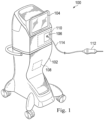
- Fig. 1 is a diagram showing an illustrative ophthalmic surgical system 100.
- the ophthalmic surgical system 100 includes a surgical console 102 and an ophthalmic surgical tool 112.
- the ophthalmic surgical tool 112 is in fluid communication with the console 102 through a fluid infusion line 114.
- the surgical console 102 includes a display screen 104 and a fluid delivery system 110.
- the surgical console 102 is configured to be mobile and may be used by a user, such as a health care provider, to perform ophthalmic surgical procedures.
- the surgical console 102 may also include a control system 108 that may be configured to process, receive, and store data to perform various functions associated with the ophthalmic surgical tool 112.
- the display screen 104 may communicate information to the user, and in some implementations, may show data relating to system operation and performance during a surgical procedure.
- the display screen 104 is a touchscreen that allows the operator to interact with the surgical console 102 through a graphical user interface.
- the fluid delivery system 110 may include a cassette 106 that is removably insertable into the fluid delivery system 100.
- the cassette 106 may include components of the fluid delivery system 110 that may come into contact with patient fluids and tissue.
- the cassette 106 may include a fluid storage container and the fluid infusion line 114.
- the cassette 106 may include components of other systems such as an aspiration system (not shown).
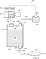
- Fig. 2 is a diagram showing an illustrative fluid delivery system 200 with a fluid storage container 202.
- the fluid delivery system 200 may correspond to the fluid delivery system 110 described above.
- the fluid delivery system 200 includes a pressure source 212 having a pump 226, a fluid source 214, and a fluid infusion line 224.
- the fluid storage container 202 includes a fluid chamber 204 for storing infusion fluid 206, a pressure inlet 208 with a filter 220, a fluid inflow port 210, and a fluid outflow port 222.
- the fluid delivery system 200 may utilize a cassette (e.g. 106, Fig. 1 ) that is insertable into the surgical console (e.g. 102, Fig. 1 ).
- the cassette may include the fluid storage container 202 and the fluid infusion line 224.
- the cassette may be structurally configured such that, when inserted into the console, the fluid inflow port 210 and pressure inlet 208 are appropriately connected to the fluid source 214 and the pressure source 212, respectively.
- the pressure source 212 may be a compressor or pump that is integrated into the surgical console (e.g., 102, Fig. 1 ).
- the pressure source 212 may be provided by a machine (e.g., a pump) separate from the console that is connectable to the surgical console through a pressure line.
- the pressure source 212 is connectable to the pressure inlet 208 of the fluid storage container 202 through the pressure line 216, such as a conduit.
- the pressure line 216 provides fluid communication between the pressure inlet 208 and the pressure source 212.
- the pressure source 212 is configured to apply both positive and negative pressure relative to atmospheric pressure to the fluid storage container 202 through the pressure inlet 208. Specifically, the pressure source 212 is adapted to apply a negative pressure (i.e., a vacuum) to the fluid storage container 202 to degas the infusion fluid 206 stored therein. The pressure source 212 is also adapted to apply positive pressure to push the infusion fluid 206 out of the fluid storage container 202, through the fluid infusion line 224 and into a patient's eye.
- a negative pressure i.e., a vacuum
- the pressure source 212 utilizes a Venturi pump 226 to apply negative pressure to the fluid storage container.
- the pressure source causes a fluid to flow from the pressure source 212, through the Venturi pump 226, and to a muffler 228.
- the Venturi pump 226 includes a narrower portion of tubing. Because speed increases through the narrow portion, pressure drops, thereby creating a vacuum. In this manner, the pressure source 212 can apply negative pressure to the pressure inlet 208.
- Other types of pumps for providing a vacuum may be used as well.
- exemplary implementation in Fig. 2 uses a single interface between the container 202 and the pressure source 212
- other implementations include two separate pressure interfaces; one for having positive pressure applied and one for having negative pressure applied.
- two separate pressure lines may connect the two pressure interfaces to the pressure source 212.
- the pressure source that provides a positive pressure may be a separate piece of machinery than the pressure source that provides a negative pressure.
- a pump may provide vacuum or negative pressure and a compressor may provide positive pressure.
- the fluid source 214 provides an infusion fluid to the fluid storage container 202.
- the infusion fluid may be, for example, a balanced salt solution (BSS).
- BSS balanced salt solution
- the infusion fluid may be provided to the fluid storage container 202 in any of a variety of manners.
- the fluid source 214 may include a fluid tank that is sized to hold a substantially larger quantity of fluid than the fluid storage container 202. Such a fluid tank may then be used to fill the fluid storage container 202 with the infusion fluid as needed.
- the fluid source 214 may be a fluid tank that is external to the surgical console 102. In either case, the fluid storage container 202 is connectable to the fluid source 214 through a fluid line 218. The fluid line 218 thus provides fluid communication between the fluid source 214 and the fluid inflow interface 210 of the fluid storage container 202.
- the chamber 204 of the fluid storage container 202 is filled with an infusion fluid 206.
- the chamber 204 may be sized such that the amount of fluid within the chamber 206 is generally sufficient for a single surgical procedure. In some examples, however, the chamber 204 may be sized to hold a smaller quantity of infusion fluid. In such a case, the chamber 204 may be refilled during a surgical procedure.
- the pressure inlet 208 may include a pressure interface 207 that allows the pressure inlet 208 to connect with the pressure line 216 such that a fluid-tight seal is formed.
- the pressure interface 207 may be a selectively attachable interface, such as a quick disconnect fitting or other interface. In some examples, the pressure interface 207 is a Luer fitting.
- the pressure inlet 208 allows fluid communication between the chamber 204 and the pressure source 212.
- the pressure inlet 208 includes the filter 220.
- the filter 220 is structurally configured to allow gaseous fluid to pass therethrough and prevent liquid fluid from passing therethrough.
- the infusion fluid 206 i.e., BSS
- BSS infusion fluid
- the fluid inflow port 210 includes an interface 209 that allows the fluid inflow port 210 to connect to the fluid line 218 such that a fluid-tight seal is formed.
- the interface 209 may be a selectively attachable interface, such as a quick disconnect fitting or other interface. In some examples, the interface 209 is a Luer fitting.
- the fluid line 218 provides fluid communication between the fluid source 214 and the fluid inflow port 210.
- the fluid inflow port 210 allows fluid communication between the chamber 204 and the fluid line 218.
- the fluid inflow port 210 may include a one-way valve that allows fluid to flow into the chamber 204 but prevents fluid from flowing out of the chamber 204.
- the fluid outflow port 222 includes an interface 211 that allows the fluid outflow port 222 to connect to the fluid infusion line 224 such that a fluid-tight seal is formed.
- the fluid outflow port 222 thus provides fluid communication between the chamber 204 and the fluid infusion line 224.
- the fluid infusion line 224 provides fluid communication between the fluid outflow port 222 and the ophthalmic surgical tool 112 that injects the infusion fluid into the patient's eye.
- the fluid outflow port 222 may include a one-way valve that allows fluid to flow out of the chamber 204 but prevents fluid from flowing into the chamber 204.
- the fluid outflow port 222 may also include a stop valve 223 or check valve to selectively prevent or allow fluid from flowing through the fluid outflow port 222.
- the control system may manage the various components to direct fluid as desired.
- the chamber 204 may be empty.
- the control system 108 may operate a pump 230 to cause the fluid from the fluid source 214 to be pumped into the chamber 204 to fill the chamber.
- the stop valve 223 of the fluid outflow port 222 may be closed so as to prevent fluid from flowing out of the fluid outflow port 222.
- the infusion fluid 206 may be pumped into the chamber 204 until the fluid level reaches a certain threshold level 225 that is lower than the top of the chamber 204.
- control system 108 may apply a negative pressure to the pressure inlet 208 through use of the pressure source 212 and the pump 226.
- the negative pressure, or vacuum, that is applied can degas the infusion fluid 206 stored within the chamber 204. In other words, gas bubbles within the infusion fluid solution may be removed from the infusion fluid solution.
- the solution may be ready for infusion into the patient's eye.
- the control system 108 may thus apply positive pressure to the pressure inlet 208.
- the stop valve 223 of the fluid outflow port 222 may be open so as to allow fluid flow therethrough.
- the positive pressure at the pressure inlet 208 causes the infusion fluid to be pushed out of the chamber 204, into the fluid infusion line 224, through the ophthalmic surgical tool 112, and into the patient's eye.
- the magnitude of the positive pressure may be controlled so as to provide the desired flow rate of infusion fluid 206 to the patient's eye.
- the control system 108 may include a processor and a memory.
- the memory may store machine readable instructions that when executed by the processor, cause the control system 108 to perform various tasks.
- the control system 108 may send control signals to the pressure source 212 and the fluid source 214. Such control signals may activate either the pressure source 212 or the fluid source 214 to behave as desired at designated points in time.
- the control system 108 may cause the fluid source 214 to fill the fluid storage container 202 with fluid 206.
- the control system 108 may cause the pressure source 212 to apply a negative pressure to degas the fluid 206 within the fluid storage container 202.
- the control system 108 may then cause the pressure source 212 to apply positive pressure to the fluid storage container 202 to push the fluid 206 out of the fluid storage container 202.
- Fig. 3 is a diagram showing an embodiment of a fluid delivery system 300 with dual fluid storage containers 202, 302.
- the second fluid storage container 302 includes a chamber 304 adapted to hold a quantity of fluid 306, a pressure inlet 308 with a filter 320, a fluid inflow port 310, and a fluid outflow port 322.
- the fluid line 218 includes a switch valve 318 that allows fluid from the fluid source 214 to be directed to either the first fluid storage container 202 or the second fluid storage container 302.
- the fluid infusion line 224 includes a switch valve 324 that allows fluid from either the first fluid storage container 202 or the second fluid storage container 302 to be directed to the ophthalmic surgical tool 112.
- the pressure lines 301, 303 connect the pressure source to the pressure inlets 208, 308 of the fluid storage containers 202, 302 through a switch valve 316.
- the first pressure line 301 may be used for applying positive pressure and the second pressure line 303 may be used for applying negative pressure.
- positive pressure may be applied to one fluid storage container while negative pressure is applied to the other and vice versa.
- Fig. 4 is a flowchart showing a process 400 for providing fluid through the fluid delivery system 300 that includes the two fluid storage containers 202, 302. Steps performed on the first fluid storage container 202 are shown in the left column 402 and the steps performed on the second fluid storage container 302 are shown in the right column 404. Reference numeral 406 identifies a starting point in time, where the first fluid storage container 202 is filled with infusion fluid and the second fluid storage container 302 is empty.
- infusion fluid is pushed out of the first fluid storage container 202 by applying positive pressure to the pressure inlet 208 of the first fluid storage container 202.
- steps 414 and 416 are performed on the second fluid storage container 302.
- the second fluid storage container 302 is filled with infusion fluid.
- the infusion fluid solution within the second fluid storage container 302 is degassed by applying a negative pressure to the pressure inlet 308 of the second fluid storage container 302.
- the process 400 switches. Specifically, between time points 408 and 410, at step 422, infusion fluid is pushed out of the second fluid storage container 302 by applying positive pressure to the pressure inlet 308. Meanwhile, steps 418 and 420 are performed on the first fluid storage container 202. At step 418, the first fluid storage container 202 is filled with infusion fluid. After the first fluid storage container 202 is appropriately filled, at step 420, the infusion fluid solution within the first fluid storage container 202 is degassed by applying a negative pressure to the pressure inlet 208 of the first fluid storage container 202.
- the first fluid storage container 202 is filled with degassed fluid and the second fluid storage container 302 is empty.
- the process 400 may continue by switching between the fluid storage containers 202, 302 as described above. Specifically, while infusion fluid is being pressurized out of one fluid storage container, the other fluid storage container is being filled and degassed. Thus, a steady flow of degassed infusion fluid can be provided to the patient's eye.
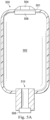
- Figs. 5A and 5B are diagrams showing illustrative fluid delivery bags capable of being degassed before infusion.
- the fluid delivery bags may store an infusion fluid.
- the bags may be flexible so that when squeezed, the infusion fluid within is pressed out of the bag and into the patient's eye.
- some surgical consoles e.g., 102, Fig. 1
- Fig. 5A illustrates an example in which the degassing interface 504 is at a top 501 of a bag 500.
- the bag 500 includes the degassing interface 504 with a filter 506, an interior chamber 502, and a fluid outflow port 510 with an outflow interface 508.
- the outflow interface 508 may be connectable to a fluid infusion line (e.g., 224, Fig. 2 ).
- the degassing interface 504 may be connectable to a pressure source (e.g. 212, Fig. 2 ) through a pressure line.
- the degassing interface 504 includes a filter 506 that may allow gaseous fluids to pass through preventing liquid fluids from passing through.
- the filter 506 may be, for example, a semipermeable membrane.
- gas bubbles within the infusion fluid solution may be pulled out of the solution. But, the infusion fluid does not pass through the filter 506. Thus, the infusion fluid solution within the chamber 502 can be degassed.
- Fig. 5B illustrates an example in which the degassing interface 512 is at a bottom 503 of a bag 520.
- the bag 520 includes the degassing interface 512 with a filter 514, and a fluid outflow port 510 with an outflow interface 508.
- the bag also includes a snorkel 516 that extends into the center portion of the chamber 502.
- the fluid outflow port 510 may include an annular channel 518 that surrounds the snorkel 516.
- the outflow interface 508 may be connectable to a fluid infusion line (e.g., 224, Fig. 2 ).
- fluid flowing out of the chamber 502 passes through the annular channel 518, through the outflow interface 508, and into a fluid infusion line.
- the degassing interface 512 may be connectable to a pressure source (e.g. 212, Fig. 2 ) through a pressure line.
- the degassing interface 504 includes a filter 514 that may allow gaseous fluids to pass through preventing liquid fluids from passing through.
- the filter 514 may be, for example, a semipermeable membrane.
- the snorkel 516 may be any suitable length.
- the snorkel 516 may be relatively short and extend only a small distance from the bottom 503 of the bag 520.
- the snorkel 516 may be relatively long and extend to a point near the top 501 of the bag 520.
- both degassing interface 504 as illustrated in Fig. 5A and degassing interface 512 as illustrated in Fig. 5B may be included within a single bag.
- Fig. 6 is a flowchart illustrating a method 600 for degassing fluid before infusion into a patient's eye.
- the method includes a step 602 for connecting a fluid outflow port of a fluid storage container to a fluid infusion line.
- the fluid infusion line provides fluid communication between the fluid storage container and an ophthalmic surgical tool.
- the pressure inlet of the fluid storage container is connected to a pressure source.
- the pressure source is capable of applying both positive and negative pressure to the fluid storage container.
- the pressure inlet includes a filter, such as a semipermeable membrane, that allows gas to pass therethrough but prevents liquid from flowing therethrough.
- the pressure source applies negative pressure to the pressure inlet.
- gas within the chamber of the fluid storage container will exit the chamber through the membrane. Additionally, gas bubbles within the infusion fluid solution will exit the chamber. In other words, the infusion fluid solution is degassed.
Landscapes
- Health & Medical Sciences (AREA)
- Life Sciences & Earth Sciences (AREA)
- Public Health (AREA)
- Biomedical Technology (AREA)
- Heart & Thoracic Surgery (AREA)
- Engineering & Computer Science (AREA)
- Veterinary Medicine (AREA)
- Animal Behavior & Ethology (AREA)
- General Health & Medical Sciences (AREA)
- Anesthesiology (AREA)
- Hematology (AREA)
- Vascular Medicine (AREA)
- Emergency Medicine (AREA)
- Ophthalmology & Optometry (AREA)
- Infusion, Injection, And Reservoir Apparatuses (AREA)
Claims (6)
- Système de distribution de fluide (200) pour fournir un fluide sous pression destiné à être perfusé dans l'œil d'un patient, comprenant :une source de pression (212) capable de produire sélectivement une pression de fluide positive et négative dans un premier récipient de stockage de fluide et un second récipient de stockage de fluide ;une source de fluide de perfusion (214) ;une ligne de perfusion de fluide (224) ;un premier récipient de stockage de fluide (202) comprenant :une première chambre (204) ;un premier orifice de sortie de fluide (222) en communication avec la ligne de perfusion de fluide pour fournir une communication fluidique entre la première chambre et la ligne de perfusion de fluide ;une première entrée de pression (208) en communication avec la source de pression (212) ; etun premier filtre (220) disposé entre la première entrée de pression et la première chambre ; etun second récipient de stockage de fluide (302) comprenant :une seconde chambre (304) ;un second orifice de sortie de fluide (322) en communication avec la ligne de perfusion de fluide pour fournir une communication fluidique entre la seconde chambre et la ligne de perfusion de fluide ;une seconde entrée de pression (308) en communication avec la source de pression (212) ; etun second filtre (320) disposé entre la seconde entrée de pression (308) et la seconde chambre (304) ;la source de fluide de perfusion (214) étant en communication avec les premier et second récipients de stockage de fluide ; etun système de commande (108) configuré pour remplir le premier récipient de stockage de fluide (202) et le second récipient de stockage de fluide (302) avec du fluide de perfusion provenant de la source de fluide de perfusion (214) ; etle système de commande (108) étant configuré pour amener la source de pression à appliquer sélectivement une pression négative ou une pression positive à la première chambre (204) et à la seconde chambre (304) de telle sorte que la pression négative agisse sur le fluide de perfusion dans l'une des première et seconde chambres pour dégazer le fluide de perfusion et que la pression positive agisse pour pousser le fluide de perfusion hors de l'autre des première et seconde chambres et dans la ligne de perfusion de fluide (224) ;le système de commande (108) étant configuré pour appliquer une pression positive au premier récipient de stockage de fluide (202) pendant une période de temps et, pendant la période de temps, provoquer séquentiellement le remplissage du second récipient de stockage de fluide (302) avec du fluide de perfusion et appliquer une pression négative au second récipient de stockage de fluide (302).
- Système de distribution de fluide selon la revendication 1, le premier récipient de stockage de fluide (202) et le second récipient de stockage de fluide (302) comprenant en outre des orifices d'entrée de fluide (210) pouvant être reliés à la source de fluide.
- Système de distribution de fluide selon la revendication 1, les premier et second filtres (320) comprenant une membrane semi-perméable.
- Procédé de fonctionnement du système (200) pour fournir un fluide sous pression destiné à être perfusé dans l'œil d'un patient selon la revendication 1,
le procédé comprenant :le remplissage (406) du premier récipient de stockage de fluide (202) avec du fluide de perfusion provenant de la source de fluide de perfusion (214) ;l'application d'une pression négative au premier récipient de stockage de fluide (202) pour dégazer le fluide de perfusion à l'intérieur du premier récipient de stockage de fluide ;avec la source de pression (212), l'application (412) d'une pression positive au premier récipient de stockage de fluide (202) pour pousser le fluide de perfusion hors du premier récipient de stockage de fluide à travers le premier orifice de sortie de fluide (222) et dans la ligne de perfusion de fluide (224) ;pendant l'application d'une pression positive au premier récipient de stockage de fluide (202), le remplissage (414) d'un second récipient de stockage de fluide (302) avec du fluide de perfusion et l'application (416) d'une pression négative au second récipient de stockage de fluide pour dégazer le fluide de perfusion dans le second récipient de stockage de fluide (302) ;l'arrêt de l'application de la pression positive au premier récipient de stockage de fluide (202) ;avec la source de pression (212), l'application (422) d'une pression positive au second récipient de stockage de fluide (202) pour pousser le fluide hors du second récipient de stockage de fluide (302) à travers le second orifice de sortie de fluide (322) et dans la ligne de perfusion de fluide (224). - Procédé selon la revendication 4, comprenant en outre :la liaison d'un orifice d'entrée de fluide (210) du premier récipient de stockage de fluide à une source de fluide du système de distribution de fluide ; etavant l'application de la pression négative, le remplissage du premier récipient de stockage de fluide avec du fluide de perfusion provenant de la source de fluide.
- Procédé selon la revendication 4, comprenant en outre l'action de pousser (422) le fluide hors d'un second récipient de stockage de fluide (302) tout en remplissant (418) le premier récipient de stockage de fluide (202) et en dégazant (420) le fluide dans le premier récipient de stockage de fluide.
Applications Claiming Priority (2)
| Application Number | Priority Date | Filing Date | Title |
|---|---|---|---|
| US15/077,575 US20170273826A1 (en) | 2016-03-22 | 2016-03-22 | Fluid storage container degassing systems and methods |
| PCT/IB2017/051664 WO2017163202A1 (fr) | 2016-03-22 | 2017-03-22 | Systèmes et procédés de dégazage de récipient de stockage de fluide |
Publications (2)
| Publication Number | Publication Date |
|---|---|
| EP3389751A1 EP3389751A1 (fr) | 2018-10-24 |
| EP3389751B1 true EP3389751B1 (fr) | 2024-12-11 |
Family
ID=58410402
Family Applications (1)
| Application Number | Title | Priority Date | Filing Date |
|---|---|---|---|
| EP17713466.5A Active EP3389751B1 (fr) | 2016-03-22 | 2017-03-22 | Systeme d'administration de fluide |
Country Status (7)
| Country | Link |
|---|---|
| US (1) | US20170273826A1 (fr) |
| EP (1) | EP3389751B1 (fr) |
| JP (1) | JP6962925B2 (fr) |
| CN (1) | CN108697865A (fr) |
| AU (1) | AU2017236690A1 (fr) |
| CA (1) | CA3012965A1 (fr) |
| WO (1) | WO2017163202A1 (fr) |
Families Citing this family (9)
| Publication number | Priority date | Publication date | Assignee | Title |
|---|---|---|---|---|
| US9205186B2 (en) | 2013-03-14 | 2015-12-08 | Abbott Medical Optics Inc. | System and method for providing pressurized infusion |
| US11357907B2 (en) * | 2017-02-10 | 2022-06-14 | Johnson & Johnson Surgical Vision, Inc. | Apparatus, system, and method of gas infusion to allow for pressure control of irrigation in a surgical system |
| NL2019884B1 (en) * | 2017-11-10 | 2019-05-17 | Crea Ip B V | Pressure control unit for an ophthalmic surgical system |
| NL2019887B1 (en) | 2017-11-10 | 2019-05-17 | Crea Ip B V | Method and system for active irrigation of an ophthalmic surgical site |
| US11154421B2 (en) * | 2018-04-20 | 2021-10-26 | Johnson & Johnson Surgical Vision, Inc. | System and method for providing pressurized infusion transfer reservoirs |
| CN109276772A (zh) * | 2018-11-24 | 2019-01-29 | 陕西省人民医院 | 一种泌尿外科用可控温度和流速膀胱冲洗装置 |
| US20210178031A1 (en) * | 2019-12-17 | 2021-06-17 | Johnson & Johnson Surgical Vision, Inc. | Rotary valve configuration for a surgical cassette |
| AU2020410412A1 (en) | 2019-12-17 | 2022-08-11 | Johnson & Johnson Surgical Vision, Inc. | Systems and methods for providing a pulseless peristaltic pump |
| WO2022130213A1 (fr) | 2020-12-17 | 2022-06-23 | Alcon Inc. | Soupape automatique de perfusion |
Family Cites Families (15)
| Publication number | Priority date | Publication date | Assignee | Title |
|---|---|---|---|---|
| US5032111A (en) * | 1987-09-22 | 1991-07-16 | Vitreoretinal Development, Inc. | Method and apparatus for ocular perfusion |
| US4976707A (en) * | 1988-05-04 | 1990-12-11 | Sherwood Medical Company | Fluid collection, storage and infusion apparatus |
| CN2624930Y (zh) * | 2003-06-17 | 2004-07-14 | 江西洪达医疗器械集团有限公司 | 滴斗可变量式输液器 |
| CN2712346Y (zh) * | 2004-04-18 | 2005-07-27 | 吕海洋 | 医用配药器 |
| US7326183B2 (en) * | 2005-09-28 | 2008-02-05 | Alcon, Inc. | Intraocular pressure control |
| CN2936272Y (zh) * | 2006-06-09 | 2007-08-22 | 株洲市人民医院 | 一种加压输液、排气泵 |
| WO2008157674A1 (fr) * | 2007-06-19 | 2008-12-24 | Yablon, Jay, R. | Système de suppression d'affaissement de la chambre suite à une occlusion pour un appareil chirurgical et procédé d'utilisation |
| US8696626B2 (en) * | 2008-07-30 | 2014-04-15 | Claudia F. E. Kirsch | Debubbler |
| US8343098B2 (en) * | 2009-06-29 | 2013-01-01 | Acist Medical Systems, Inc. | Method and system for removing air from a flow path of a fluid injection device |
| US8771228B2 (en) * | 2011-01-06 | 2014-07-08 | Carefusion 303, Inc. | IV pump adapted for generic tubing |
| US8795231B2 (en) * | 2011-05-10 | 2014-08-05 | Medtronic Minimed, Inc. | Automated reservoir fill system |
| US9421129B2 (en) * | 2012-04-02 | 2016-08-23 | Ocuject, Llc | Intraocular delivery devices and methods therefor |
| US9132229B2 (en) * | 2012-09-13 | 2015-09-15 | Alcon Research, Ltd. | System and method of priming a surgical cassette |
| KR102431008B1 (ko) * | 2013-05-23 | 2022-08-09 | 뉴아이브이 메디컬 코퍼레이션 | 공압적으로 결합된 직접 구동 유체 제어 시스템 및 방법 |
| US10537471B2 (en) * | 2014-04-17 | 2020-01-21 | Novartis Ag | Hydraulic pump for ophthalmic surgery |
-
2016
- 2016-03-22 US US15/077,575 patent/US20170273826A1/en not_active Abandoned
-
2017
- 2017-03-22 AU AU2017236690A patent/AU2017236690A1/en not_active Abandoned
- 2017-03-22 JP JP2018543392A patent/JP6962925B2/ja active Active
- 2017-03-22 WO PCT/IB2017/051664 patent/WO2017163202A1/fr not_active Ceased
- 2017-03-22 CN CN201780010164.4A patent/CN108697865A/zh active Pending
- 2017-03-22 CA CA3012965A patent/CA3012965A1/fr not_active Abandoned
- 2017-03-22 EP EP17713466.5A patent/EP3389751B1/fr active Active
Also Published As
| Publication number | Publication date |
|---|---|
| WO2017163202A1 (fr) | 2017-09-28 |
| US20170273826A1 (en) | 2017-09-28 |
| CN108697865A (zh) | 2018-10-23 |
| JP2019509097A (ja) | 2019-04-04 |
| JP6962925B2 (ja) | 2021-11-05 |
| CA3012965A1 (fr) | 2017-09-28 |
| AU2017236690A1 (en) | 2018-08-02 |
| EP3389751A1 (fr) | 2018-10-24 |
Similar Documents
| Publication | Publication Date | Title |
|---|---|---|
| EP3389751B1 (fr) | Systeme d'administration de fluide | |
| EP0343286B1 (fr) | Pompe volumétrique pour perfusion parentérale | |
| EP2802366B1 (fr) | Systèmes de distribution de fluide à un pansement de traitement de plaie | |
| CN101277735B (zh) | 用于控制眼内压力的显微外科系统 | |
| CA2799463C (fr) | Ensemble de tubulure comportant une porte amelioree pour la connexion de flacons | |
| CN102711864B (zh) | 具有用于连接药瓶的门的管组 | |
| CN101969896B (zh) | 眼科手术系统 | |
| EP3723679B1 (fr) | Systèmes et procédés de mélange de gaz dans un équipement chirurgical oculaire | |
| US9233196B2 (en) | Method for pre-filling a hemodialysis apparatus | |
| JP6923162B2 (ja) | 輸液装置 | |
| US10576197B2 (en) | Blood purification device and priming method | |
| US20090118680A1 (en) | Automatic gas filling consumable | |
| JP2017520365A (ja) | 血液処理セッションの完了後に流量増加によって血液フィルタから流体を除去するための方法及び該方法を実行するための処理機器 | |
| JP2019181061A (ja) | 輸液セットのプライミング方法及び輸液セット | |
| US11590334B2 (en) | Blood circuit adapter set and blood circuit | |
| JP7499542B1 (ja) | 気泡除去機構 | |
| KR102710202B1 (ko) | 복막 투석 환자의 정적 압력을 결정하기 위한 장치 | |
| JP2025501172A (ja) | 静脈内圧力アセンブリ | |
| CN108697838B (zh) | 用于执行体外的血液治疗的设备 | |
| JP2006223570A (ja) | 医療用容器 | |
| HK40023696B (en) | Treatment apparatus for withdrawing blood from an extracorporeal blood circuit | |
| CN106730137A (zh) | 医用输液装置 | |
| CN106902413A (zh) | 医用输液装置 | |
| JP2011217945A (ja) | 点滴筒 | |
| CN106730135A (zh) | 医用输液装置 |
Legal Events
| Date | Code | Title | Description |
|---|---|---|---|
| STAA | Information on the status of an ep patent application or granted ep patent |
Free format text: STATUS: UNKNOWN |
|
| STAA | Information on the status of an ep patent application or granted ep patent |
Free format text: STATUS: THE INTERNATIONAL PUBLICATION HAS BEEN MADE |
|
| PUAI | Public reference made under article 153(3) epc to a published international application that has entered the european phase |
Free format text: ORIGINAL CODE: 0009012 |
|
| STAA | Information on the status of an ep patent application or granted ep patent |
Free format text: STATUS: REQUEST FOR EXAMINATION WAS MADE |
|
| 17P | Request for examination filed |
Effective date: 20180719 |
|
| AK | Designated contracting states |
Kind code of ref document: A1 Designated state(s): AL AT BE BG CH CY CZ DE DK EE ES FI FR GB GR HR HU IE IS IT LI LT LU LV MC MK MT NL NO PL PT RO RS SE SI SK SM TR |
|
| AX | Request for extension of the european patent |
Extension state: BA ME |
|
| RIN1 | Information on inventor provided before grant (corrected) |
Inventor name: SANCHEZ, JR., ROBERT JOSEPH |
|
| DAV | Request for validation of the european patent (deleted) | ||
| DAX | Request for extension of the european patent (deleted) | ||
| RAP1 | Party data changed (applicant data changed or rights of an application transferred) |
Owner name: ALCON INC. |
|
| STAA | Information on the status of an ep patent application or granted ep patent |
Free format text: STATUS: EXAMINATION IS IN PROGRESS |
|
| 17Q | First examination report despatched |
Effective date: 20201125 |
|
| P01 | Opt-out of the competence of the unified patent court (upc) registered |
Effective date: 20230507 |
|
| REG | Reference to a national code |
Ref country code: DE Ref legal event code: R079 Ref document number: 602017086680 Country of ref document: DE Free format text: PREVIOUS MAIN CLASS: A61M0005360000 Ipc: A61F0009000000 |
|
| GRAP | Despatch of communication of intention to grant a patent |
Free format text: ORIGINAL CODE: EPIDOSNIGR1 |
|
| STAA | Information on the status of an ep patent application or granted ep patent |
Free format text: STATUS: GRANT OF PATENT IS INTENDED |
|
| RIC1 | Information provided on ipc code assigned before grant |
Ipc: A61M 5/38 20060101ALI20240621BHEP Ipc: A61M 5/36 20060101ALI20240621BHEP Ipc: A61M 3/02 20060101ALI20240621BHEP Ipc: A61F 9/00 20060101AFI20240621BHEP |
|
| INTG | Intention to grant announced |
Effective date: 20240710 |
|
| GRAS | Grant fee paid |
Free format text: ORIGINAL CODE: EPIDOSNIGR3 |
|
| GRAA | (expected) grant |
Free format text: ORIGINAL CODE: 0009210 |
|
| STAA | Information on the status of an ep patent application or granted ep patent |
Free format text: STATUS: THE PATENT HAS BEEN GRANTED |
|
| AK | Designated contracting states |
Kind code of ref document: B1 Designated state(s): AL AT BE BG CH CY CZ DE DK EE ES FI FR GB GR HR HU IE IS IT LI LT LU LV MC MK MT NL NO PL PT RO RS SE SI SK SM TR |
|
| REG | Reference to a national code |
Ref country code: GB Ref legal event code: FG4D |
|
| REG | Reference to a national code |
Ref country code: CH Ref legal event code: EP |
|
| REG | Reference to a national code |
Ref country code: IE Ref legal event code: FG4D |
|
| REG | Reference to a national code |
Ref country code: DE Ref legal event code: R096 Ref document number: 602017086680 Country of ref document: DE |
|
| REG | Reference to a national code |
Ref country code: NL Ref legal event code: FP |
|
| REG | Reference to a national code |
Ref country code: LT Ref legal event code: MG9D |
|
| PG25 | Lapsed in a contracting state [announced via postgrant information from national office to epo] |
Ref country code: HR Free format text: LAPSE BECAUSE OF FAILURE TO SUBMIT A TRANSLATION OF THE DESCRIPTION OR TO PAY THE FEE WITHIN THE PRESCRIBED TIME-LIMIT Effective date: 20241211 |
|
| PG25 | Lapsed in a contracting state [announced via postgrant information from national office to epo] |
Ref country code: FI Free format text: LAPSE BECAUSE OF FAILURE TO SUBMIT A TRANSLATION OF THE DESCRIPTION OR TO PAY THE FEE WITHIN THE PRESCRIBED TIME-LIMIT Effective date: 20241211 |
|
| PG25 | Lapsed in a contracting state [announced via postgrant information from national office to epo] |
Ref country code: BG Free format text: LAPSE BECAUSE OF FAILURE TO SUBMIT A TRANSLATION OF THE DESCRIPTION OR TO PAY THE FEE WITHIN THE PRESCRIBED TIME-LIMIT Effective date: 20241211 |
|
| PG25 | Lapsed in a contracting state [announced via postgrant information from national office to epo] |
Ref country code: ES Free format text: LAPSE BECAUSE OF FAILURE TO SUBMIT A TRANSLATION OF THE DESCRIPTION OR TO PAY THE FEE WITHIN THE PRESCRIBED TIME-LIMIT Effective date: 20241211 |
|
| PG25 | Lapsed in a contracting state [announced via postgrant information from national office to epo] |
Ref country code: NO Free format text: LAPSE BECAUSE OF FAILURE TO SUBMIT A TRANSLATION OF THE DESCRIPTION OR TO PAY THE FEE WITHIN THE PRESCRIBED TIME-LIMIT Effective date: 20250311 |
|
| PG25 | Lapsed in a contracting state [announced via postgrant information from national office to epo] |
Ref country code: LV Free format text: LAPSE BECAUSE OF FAILURE TO SUBMIT A TRANSLATION OF THE DESCRIPTION OR TO PAY THE FEE WITHIN THE PRESCRIBED TIME-LIMIT Effective date: 20241211 Ref country code: GR Free format text: LAPSE BECAUSE OF FAILURE TO SUBMIT A TRANSLATION OF THE DESCRIPTION OR TO PAY THE FEE WITHIN THE PRESCRIBED TIME-LIMIT Effective date: 20250312 |
|
| PG25 | Lapsed in a contracting state [announced via postgrant information from national office to epo] |
Ref country code: RS Free format text: LAPSE BECAUSE OF FAILURE TO SUBMIT A TRANSLATION OF THE DESCRIPTION OR TO PAY THE FEE WITHIN THE PRESCRIBED TIME-LIMIT Effective date: 20250311 |
|
| REG | Reference to a national code |
Ref country code: AT Ref legal event code: MK05 Ref document number: 1749793 Country of ref document: AT Kind code of ref document: T Effective date: 20241211 |
|
| PG25 | Lapsed in a contracting state [announced via postgrant information from national office to epo] |
Ref country code: SM Free format text: LAPSE BECAUSE OF FAILURE TO SUBMIT A TRANSLATION OF THE DESCRIPTION OR TO PAY THE FEE WITHIN THE PRESCRIBED TIME-LIMIT Effective date: 20241211 |
|
| PG25 | Lapsed in a contracting state [announced via postgrant information from national office to epo] |
Ref country code: PL Free format text: LAPSE BECAUSE OF FAILURE TO SUBMIT A TRANSLATION OF THE DESCRIPTION OR TO PAY THE FEE WITHIN THE PRESCRIBED TIME-LIMIT Effective date: 20241211 |
|
| PG25 | Lapsed in a contracting state [announced via postgrant information from national office to epo] |
Ref country code: IS Free format text: LAPSE BECAUSE OF FAILURE TO SUBMIT A TRANSLATION OF THE DESCRIPTION OR TO PAY THE FEE WITHIN THE PRESCRIBED TIME-LIMIT Effective date: 20250411 |
|
| PG25 | Lapsed in a contracting state [announced via postgrant information from national office to epo] |
Ref country code: PT Free format text: LAPSE BECAUSE OF FAILURE TO SUBMIT A TRANSLATION OF THE DESCRIPTION OR TO PAY THE FEE WITHIN THE PRESCRIBED TIME-LIMIT Effective date: 20250411 |
|
| PG25 | Lapsed in a contracting state [announced via postgrant information from national office to epo] |
Ref country code: EE Free format text: LAPSE BECAUSE OF FAILURE TO SUBMIT A TRANSLATION OF THE DESCRIPTION OR TO PAY THE FEE WITHIN THE PRESCRIBED TIME-LIMIT Effective date: 20241211 |
|
| PG25 | Lapsed in a contracting state [announced via postgrant information from national office to epo] |
Ref country code: AT Free format text: LAPSE BECAUSE OF FAILURE TO SUBMIT A TRANSLATION OF THE DESCRIPTION OR TO PAY THE FEE WITHIN THE PRESCRIBED TIME-LIMIT Effective date: 20241211 Ref country code: RO Free format text: LAPSE BECAUSE OF FAILURE TO SUBMIT A TRANSLATION OF THE DESCRIPTION OR TO PAY THE FEE WITHIN THE PRESCRIBED TIME-LIMIT Effective date: 20241211 |
|
| PG25 | Lapsed in a contracting state [announced via postgrant information from national office to epo] |
Ref country code: SK Free format text: LAPSE BECAUSE OF FAILURE TO SUBMIT A TRANSLATION OF THE DESCRIPTION OR TO PAY THE FEE WITHIN THE PRESCRIBED TIME-LIMIT Effective date: 20241211 |
|
| PG25 | Lapsed in a contracting state [announced via postgrant information from national office to epo] |
Ref country code: CZ Free format text: LAPSE BECAUSE OF FAILURE TO SUBMIT A TRANSLATION OF THE DESCRIPTION OR TO PAY THE FEE WITHIN THE PRESCRIBED TIME-LIMIT Effective date: 20241211 |
|
| PG25 | Lapsed in a contracting state [announced via postgrant information from national office to epo] |
Ref country code: SE Free format text: LAPSE BECAUSE OF FAILURE TO SUBMIT A TRANSLATION OF THE DESCRIPTION OR TO PAY THE FEE WITHIN THE PRESCRIBED TIME-LIMIT Effective date: 20241211 |
|
| REG | Reference to a national code |
Ref country code: DE Ref legal event code: R097 Ref document number: 602017086680 Country of ref document: DE |
|
| PG25 | Lapsed in a contracting state [announced via postgrant information from national office to epo] |
Ref country code: DK Free format text: LAPSE BECAUSE OF FAILURE TO SUBMIT A TRANSLATION OF THE DESCRIPTION OR TO PAY THE FEE WITHIN THE PRESCRIBED TIME-LIMIT Effective date: 20241211 |
|
| PG25 | Lapsed in a contracting state [announced via postgrant information from national office to epo] |
Ref country code: MC Free format text: LAPSE BECAUSE OF FAILURE TO SUBMIT A TRANSLATION OF THE DESCRIPTION OR TO PAY THE FEE WITHIN THE PRESCRIBED TIME-LIMIT Effective date: 20241211 |
|
| PLBE | No opposition filed within time limit |
Free format text: ORIGINAL CODE: 0009261 |
|
| STAA | Information on the status of an ep patent application or granted ep patent |
Free format text: STATUS: NO OPPOSITION FILED WITHIN TIME LIMIT |
|
| REG | Reference to a national code |
Ref country code: CH Ref legal event code: L10 Free format text: ST27 STATUS EVENT CODE: U-0-0-L10-L00 (AS PROVIDED BY THE NATIONAL OFFICE) Effective date: 20251022 |
|
| REG | Reference to a national code |
Ref country code: CH Ref legal event code: H13 Free format text: ST27 STATUS EVENT CODE: U-0-0-H10-H13 (AS PROVIDED BY THE NATIONAL OFFICE) Effective date: 20251023 |
|
| PG25 | Lapsed in a contracting state [announced via postgrant information from national office to epo] |
Ref country code: LU Free format text: LAPSE BECAUSE OF NON-PAYMENT OF DUE FEES Effective date: 20250322 |
|
| 26N | No opposition filed |
Effective date: 20250912 |
|
| GBPC | Gb: european patent ceased through non-payment of renewal fee |
Effective date: 20250322 |
|
| REG | Reference to a national code |
Ref country code: BE Ref legal event code: MM Effective date: 20250331 |
|
| PG25 | Lapsed in a contracting state [announced via postgrant information from national office to epo] |
Ref country code: GB Free format text: LAPSE BECAUSE OF NON-PAYMENT OF DUE FEES Effective date: 20250322 |
|
| PG25 | Lapsed in a contracting state [announced via postgrant information from national office to epo] |
Ref country code: FR Free format text: LAPSE BECAUSE OF NON-PAYMENT OF DUE FEES Effective date: 20250331 |
|
| PG25 | Lapsed in a contracting state [announced via postgrant information from national office to epo] |
Ref country code: BE Free format text: LAPSE BECAUSE OF NON-PAYMENT OF DUE FEES Effective date: 20250331 |
|
| PG25 | Lapsed in a contracting state [announced via postgrant information from national office to epo] |
Ref country code: CH Free format text: LAPSE BECAUSE OF NON-PAYMENT OF DUE FEES Effective date: 20250331 |
|
| PG25 | Lapsed in a contracting state [announced via postgrant information from national office to epo] |
Ref country code: IE Free format text: LAPSE BECAUSE OF NON-PAYMENT OF DUE FEES Effective date: 20250322 |
|
| PGFP | Annual fee paid to national office [announced via postgrant information from national office to epo] |
Ref country code: NL Payment date: 20260227 Year of fee payment: 10 |
|
| PGFP | Annual fee paid to national office [announced via postgrant information from national office to epo] |
Ref country code: DE Payment date: 20260218 Year of fee payment: 10 |
|
| PGFP | Annual fee paid to national office [announced via postgrant information from national office to epo] |
Ref country code: IT Payment date: 20260226 Year of fee payment: 10 |