EP3390077B1 - Reifen mit verbesserten abnutzungseigenschaften - Google Patents
Reifen mit verbesserten abnutzungseigenschaften Download PDFInfo
- Publication number
- EP3390077B1 EP3390077B1 EP16819626.9A EP16819626A EP3390077B1 EP 3390077 B1 EP3390077 B1 EP 3390077B1 EP 16819626 A EP16819626 A EP 16819626A EP 3390077 B1 EP3390077 B1 EP 3390077B1
- Authority
- EP
- European Patent Office
- Prior art keywords
- tread
- tyre
- reinforcing elements
- width
- measured
- Prior art date
- Legal status (The legal status is an assumption and is not a legal conclusion. Google has not performed a legal analysis and makes no representation as to the accuracy of the status listed.)
- Active
Links
Images


Classifications
-
- B—PERFORMING OPERATIONS; TRANSPORTING
- B60—VEHICLES IN GENERAL
- B60C—VEHICLE TYRES; TYRE INFLATION; TYRE CHANGING; CONNECTING VALVES TO INFLATABLE ELASTIC BODIES IN GENERAL; DEVICES OR ARRANGEMENTS RELATED TO TYRES
- B60C9/00—Reinforcements or ply arrangement of pneumatic tyres
- B60C9/18—Structure or arrangement of belts or breakers, crown-reinforcing or cushioning layers
- B60C9/20—Structure or arrangement of belts or breakers, crown-reinforcing or cushioning layers built-up from rubberised plies each having all cords arranged substantially parallel
- B60C9/2003—Structure or arrangement of belts or breakers, crown-reinforcing or cushioning layers built-up from rubberised plies each having all cords arranged substantially parallel characterised by the materials of the belt cords
- B60C9/2006—Structure or arrangement of belts or breakers, crown-reinforcing or cushioning layers built-up from rubberised plies each having all cords arranged substantially parallel characterised by the materials of the belt cords consisting of steel cord plies only
-
- B—PERFORMING OPERATIONS; TRANSPORTING
- B60—VEHICLES IN GENERAL
- B60C—VEHICLE TYRES; TYRE INFLATION; TYRE CHANGING; CONNECTING VALVES TO INFLATABLE ELASTIC BODIES IN GENERAL; DEVICES OR ARRANGEMENTS RELATED TO TYRES
- B60C11/00—Tyre tread bands; Tread patterns; Anti-skid inserts
- B60C11/03—Tread patterns
- B60C11/032—Patterns comprising isolated recesses
- B60C11/0323—Patterns comprising isolated recesses tread comprising channels under the tread surface, e.g. for draining water
-
- B—PERFORMING OPERATIONS; TRANSPORTING
- B60—VEHICLES IN GENERAL
- B60C—VEHICLE TYRES; TYRE INFLATION; TYRE CHANGING; CONNECTING VALVES TO INFLATABLE ELASTIC BODIES IN GENERAL; DEVICES OR ARRANGEMENTS RELATED TO TYRES
- B60C11/00—Tyre tread bands; Tread patterns; Anti-skid inserts
- B60C11/03—Tread patterns
- B60C11/12—Tread patterns characterised by the use of narrow slits or incisions, e.g. sipes
- B60C11/1272—Width of the sipe
- B60C11/1281—Width of the sipe different within the same sipe, i.e. enlarged width portion at sipe bottom or along its length
-
- B—PERFORMING OPERATIONS; TRANSPORTING
- B60—VEHICLES IN GENERAL
- B60C—VEHICLE TYRES; TYRE INFLATION; TYRE CHANGING; CONNECTING VALVES TO INFLATABLE ELASTIC BODIES IN GENERAL; DEVICES OR ARRANGEMENTS RELATED TO TYRES
- B60C9/00—Reinforcements or ply arrangement of pneumatic tyres
- B60C9/18—Structure or arrangement of belts or breakers, crown-reinforcing or cushioning layers
- B60C9/20—Structure or arrangement of belts or breakers, crown-reinforcing or cushioning layers built-up from rubberised plies each having all cords arranged substantially parallel
- B60C9/22—Structure or arrangement of belts or breakers, crown-reinforcing or cushioning layers built-up from rubberised plies each having all cords arranged substantially parallel the plies being arranged with all cords disposed along the circumference of the tyre
-
- B—PERFORMING OPERATIONS; TRANSPORTING
- B60—VEHICLES IN GENERAL
- B60C—VEHICLE TYRES; TYRE INFLATION; TYRE CHANGING; CONNECTING VALVES TO INFLATABLE ELASTIC BODIES IN GENERAL; DEVICES OR ARRANGEMENTS RELATED TO TYRES
- B60C2200/00—Tyres specially adapted for particular applications
- B60C2200/06—Tyres specially adapted for particular applications for heavy duty vehicles
Definitions
- the present invention relates to a tire with a radial carcass reinforcement and more particularly to a tire intended for fitting vehicles carrying heavy loads and traveling at sustained speed, such as, for example, trucks, tractors, trailers or road buses.
- the carcass reinforcement is anchored on both sides in the bead zone and is surmounted radially by a crown reinforcement made up of at least two superimposed layers. and formed of parallel wires or cables in each layer and crossed from one layer to the next making angles of between 10 ° and 45 ° with the circumferential direction.
- Said working layers, forming the working reinforcement can also be covered with at least one so-called protective layer and formed of reinforcing elements which are advantageously metallic and extensible, called elastic.
- triangulation ply can also comprise a layer of low extensibility metal wires or cables forming an angle of between 45 ° and 90 ° with the circumferential direction, this ply, called triangulation ply, being located radially between the carcass reinforcement and the first ply of so-called working top, formed of parallel wires or cables having angles at most equal to 45 ° in absolute value.
- the triangulation ply forms with at least said working ply a triangulated reinforcement, which has, under the various stresses that it undergoes, little deformation, the triangulation ply having the essential role of taking up the transverse compressive forces of which is the 'object all the reinforcement elements in the region of the crown of the tire.
- Circumferential reinforcing elements are reinforcing elements which form angles with the circumferential direction in the range + 2.5 °, - 2.5 ° around 0 °.
- the circumferential direction of the tire is the direction corresponding to the periphery of the tire and defined by the rolling direction of the tire.
- the transverse or axial direction of the tire is parallel to the axis of rotation of the tire.
- the axis of rotation of the tire is the axis around which it rotates in normal use.
- the tires thus produced effectively improve performance, in particular in terms of endurance.
- the layer of circumferential reinforcing elements is usually formed by at least one metallic cable wound to form a turn, the laying angle of which with respect to the circumferential direction is less than 2.5 °.
- the document WO 2013/053877 further describes a tire comprising a layer of circumferential reinforcing elements associated with two working layers.
- the tread that is to say the part of the tire intended to come into contact with the ground during rolling and to wear out during rolling, of a sculpture formed of elements in relief delimited by grooves whether they are of circumferential, transverse or oblique orientation.
- the objective of such a tread is to give the tread good performance when driving on dry pavement and on pavement coated with water, in particular in rainy weather.
- ridges oriented transversely or obliquely in order to cut the film of water on a roadway.
- One means of obtaining such ridges consists in providing the strip with a plurality of cutouts, these cutouts having the form of grooves or the form of incisions.
- the incisions of the grooves in that the incisions have an appropriate width to allow during rolling at least partial contact between the vis-à-vis walls delimiting these incisions and in particular during passage through contact with the ground, which cannot be the case for the grooves under normal conditions of tire use.
- partial wear of a tread is meant a state of wear corresponding to a tread thickness at most equal to the total thickness of the tread that can be worn before having to change the tire, in particular for regulatory reasons. .
- the patent application WO 02/38399-A2 describes a tread for a heavy vehicle tire, this tread comprising a plurality of circumferential and transverse grooves.
- the transverse grooves are formed by alternating recessed areas and incisions so as to have a volume of opening recesses on the tread surface when new and a volume of hidden hollows, these hidden hollows being intended to open after partial wear of the same tread.
- the presence of hidden hollows - appearing with wear allows for greater rigidity in the initial state while ensuring grip performance regardless of the level of wear of the belt.
- the documents FR 2 950 565 and WO 2010/030276 describe, for example, cutouts with longitudinal orientation in which the ratio of the width measured at the bottom of the cutout to the width measured at the surface of the tread is greater than 1.2 and cutouts with transverse orientation in which the ratio of the measured width at the bottom of the cutout over the width measured at the surface of the tread is greater than 1.
- the documents FR 3 014 022 and WO 2014/102136 describe, for example, cutouts with longitudinal orientation and cutouts with transverse orientation.
- An aim of the invention is to provide tires whose wear properties and more specifically the regularity of wear are preserved or improved whatever the use, the tires comprising a combination of longitudinal and transverse cutouts comprising hidden hollows. present on the tread.
- a tire with a radial carcass reinforcement comprising a crown reinforcement formed of at least two working crown layers of reinforcing elements, itself radially capped with a tread, said tread being joined to two beads by means of two sidewalls, the crown reinforcement comprising at least one layer of circumferential reinforcing elements, said tread comprising a tread surface intended to come into contact with a pavement and form a contact surface, said tread consisting of at least one central part extending at least in the region of the equatorial plane and two axially outer parts and having at least in said central part at least one cutout of longitudinal orientation and at least one cutout of transverse orientation, the depth, measured on a new tire in at least said central part, of said at least one cutout of longitudinal orientation being greater than or equal to 40% of the thickness of the tread, the ratio of the width measured at the bottom of said at least one cutout of longitudinal orientation over the width measured at the surface of the tread on a new tire of said at least one cutout of longitudinal orientation being
- a cutout of transverse orientation is a cutout whose mean plane of at least part of the walls of said cutout forms an angle with a radial plane of less than 35 °. This angle formed with a radial plane can be oriented in one direction or the other with respect to said radial plane.
- a cutout of transverse orientation can also be a cutout which runs continuously on either side of a mean plane as has just been described; it may also be a cutout, the walls of which undulate or zigzag around a mean plane such as has just been described.
- the depth of a cutout is the radial distance measured on a new tire between the surface of the tread and the radially innermost point of said cutout.
- the thickness of the tread is the distance measured on a new tire between a point on the surface of the tread and the orthogonal projection of said point on the surface. radially outside the crown reinforcement.
- the width between the walls of a cutout is measured on a new tire, in a section plane perpendicular to the mean plane of the walls and to the plane tangent to the surface of the tread. It is measured in a direction parallel to the plane tangent to the surface of the tread.
- a measurement at the bottom of a cutout corresponds to the largest measurement in the radially inner part of the cutout and more exactly to the largest measurement taken in a zone lying radially between the radially innermost point of said cutout and a point located at a distance from the surface of the tread equal to 25% of the depth of said cutout.
- the central part of the tread extending at least in the zone of the equatorial plane has an axial width at least as great as that of the layer of circumferential reinforcing elements.
- the inventors have indeed been able to demonstrate that the combination of cutouts with longitudinal orientation and cutouts with transverse orientation, the depth of which is greater than 40% of the thickness of the tread and the ratio of the width measured to bottom of said longitudinal cutouts over the width measured at the surface of the tread of said cutouts is greater than 1.2 and of which the ratio of the width measured at the bottom of said transverse cutouts to the width measured at the surface of the tread of said cutouts is greater or equal to 1, leads to local deformations of the crown reinforcement during the manufacture of the tire and in particular during the curing of the latter.
- the inventors intend to interpret this deformation of the crown reinforcement due to creep of uncontrolled elastomeric materials at said cutouts comprising hidden hollows during the molding and curing of said tire.
- the inventors have further demonstrated that the hollows hidden within cutouts oriented in the longitudinal direction with relatively small dimensions since they are associated with a series of transverse cutouts not comprising hidden hollows, which they '' acts of grooves or transverse incisions, also lead to a deformation in the radial direction of the constituent layers of the crown reinforcement.
- the inventors intend to interpret the results obtained with the tires according to the invention by the presence of a layer of circumferential reinforcing elements which seems to be able to reduce or even avoid said local deformations of the crown reinforcement during the curing of tires comprising longitudinal and transverse orientation cutouts the depth of which is greater than or equal to 40% of the thickness of the tread and the ratio of the width measured at the bottom of the longitudinal orientation cutouts to the width measured at the surface of the tread of the longitudinal orientation cutouts is greater than 1.2 and the ratio of the width measured at the bottom of said transverse cutouts to the width measured at the surface of the tread of said cutouts is greater than or equal to 1.
- the layer of circumferential reinforcing elements which is usually present to limit the effects of shearing between the working crown layers, seems to allow better control of the movements of the mixtures forming the tread during the curing of the tread.
- a tire comprising cutouts of longitudinal orientation comprising hidden hollows and cutouts of transverse orientation including or without hidden hollows.
- the ratio of the width measured at the bottom of said at least one cutout of transverse orientation to the width measured at the surface of the tread on a new tire of said at least one cutout transverse orientation is strictly greater than 1.2.
- the transverse orientation cutout preferably has a ratio of the width measured at the bottom of said at least one transverse orientation cutout to the width of said at least one orientation cutout. transverse measured in surface area of the tread on a new tire greater than 1.2 over its entire length.
- this condition on the ratio of the width measured at the bottom of said at least one cutout of transverse orientation over the width of said at least one cutout of transverse orientation measured at the surface of the strip bearing capacity on new tires greater than 1.2 may only be checked over part of the length of the transverse orientation cutout.
- the width measured at the bottom of said at least one transverse orientation cutout is strictly greater than 2 mm.
- the width measured at the bottom of said at least one transverse orientation cutout is less than 10 mm.
- the cutout of longitudinal orientation has a ratio of the width measured at the bottom of said at least one cutout of longitudinal orientation to the width of said at least one cutout of longitudinal orientation measured in tread surface area on a new tire greater than 1.2 over its entire length.
- this condition on the ratio of the width measured at the bottom of said at least one cutout of longitudinal orientation over the width of said at least one cutout of longitudinal orientation measured at the surface of the strip bearing on new tires greater than 1.2 may only be checked over part of the length of the longitudinal orientation cutout.
- this condition on the ratio of the width measured at the bottom of said at least one cutout of longitudinal orientation on the width of said at least one cutout of longitudinal orientation measured at the surface of the tread on a new tire greater than 1.2 can be checked intermittently over the length of the cutout of longitudinal orientation.
- the width measured at the bottom of said at least one cutout of longitudinal orientation is less than 10 mm.
- the volume notch ratio of the tread is defined according to the invention on a new tire by the ratio of the volume of cutouts to the total volume of the tread.
- the total volume of the tread is for its part defined in the sense of the invention by the volume, including the volume of all the cutouts, evaluated between the tread surface and a surface parallel to this tread surface passing through the bottom. the innermost recess of the strip.
- the axially widest working crown layer is radially inside the other working crown layers.
- the layer of circumferential reinforcing elements has an axial width greater than 0.5 ⁇ W.
- the axial widths of the layers of reinforcing elements are measured on a cross section of a tire, the tire therefore being in an uninflated state.
- At least two working crown layers have different axial widths, the difference between the axial width of the axially widest working crown layer and the axial width of the crown layer.
- axially the narrowest work being between 10 and 30 mm.
- the reinforcing elements of at least one layer of circumferential reinforcing elements are metallic reinforcing elements having a secant modulus at 0.7% elongation of between 10 and 120 GPa and a maximum tangent modulus of less than 150 GPa.
- the secant modulus of the reinforcing elements at 0.7% elongation is less than 100 GPa and greater than 20 GPa, preferably between 30 and 90 GPa and more preferably still below 80 GPa.
- the substantially constant and steep slope appears from a relative elongation of between 0.1% and 0.5%.
- the invention also advantageously provides, in order to reduce the tensile stresses acting on the axially outermost circumferential elements that the angle formed with the circumferential direction by the reinforcing elements of the working crown layers is less than 30 ° and preferably less than 25 °.
- a preferred embodiment of the invention also provides that the crown reinforcement is completed radially on the outside by at least one additional layer, called protective, of so-called elastic reinforcing elements, oriented with respect to the circumferential direction with an angle between 10 ° and 45 ° and in the same direction as the angle formed by the inextensible elements of the working layer which is radially adjacent to it.
- protective of so-called elastic reinforcing elements
- the protective layer may have an axial width less than the axial width of the narrowest working layer.
- Said protective layer may also have an axial width greater than the axial width of the narrower working layer, such that it covers the edges of the narrower working layer and, in the case of the radially upper layer as being the narrowest, as it is coupled, in the axial extension of the additional reinforcement, with the widest working crown layer over an axial width, in order to then be, axially on the outside, decoupled from said widest working layer by profiles with a thickness of at least 2 mm.
- the protective layer formed of elastic reinforcing elements may, in the case cited above, on the one hand possibly be decoupled from the edges of said narrower working layer by profiles of thickness substantially less than the thickness. profiles separating the edges of the two working layers, and on the other hand have an axial width less than or greater than the axial width of the widest crown layer.
- the crown frame is itself capped with a tread 6.
- the axial width L 41 of the first working layer 41 is equal to 252 mm.
- the axial width L 43 of the second working layer 43 is equal to 232 mm.
- the axial width L 42 of the layer of circumferential reinforcing elements 42 is equal to 194 mm.
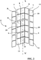
- the cutouts 8 and 10 form an incision in the surface of the tread which, in accordance with the definition given above, has a width of less than 2 mm.
- the hollow hidden under said incision reveals a groove.
- the incision makes it possible to form ridges while retaining a high rigidity of the tread, the walls coming into contact with one another at the time of contact with the ground.
- the hidden hollow forms a groove and therefore ridges, the loss of rigidity being limited due to the lesser depth of the cutout in the tread.
- the reference tires comply with figures 2-4 and their crown architecture differs in that the crown reinforcement does not include a layer of circumferential reinforcing elements.
- the reference tires show wear irregularities. Such wear irregularities can under certain conditions have negative effects on the grip properties of the tire because the surface of the contact patch can be modified. These wear irregularities can also generate vibrations, perceptible by the user and therefore a situation of discomfort for the latter. In addition, the appearance of such irregularities in wear leads to an increase in the rate of wear of the tires and therefore a shorter period of use than expected.
Landscapes
- Engineering & Computer Science (AREA)
- Mechanical Engineering (AREA)
- Tires In General (AREA)
Claims (13)
- Reifen (1) mit radialer Karkassenbewehrung (2), welcher eine Scheitelbewehrung (4) umfasst, die von wenigstens zwei Arbeitsscheitelschichten von Verstärkungselementen (41, 43) gebildet wird und ihrerseits radial von einem Laufstreifen (5) bedeckt wird, wobei der Laufstreifen über zwei Seitenwände mit zwei Wülsten verbunden ist, wobei die Scheitelbewehrung (4) wenigstens eine Schicht von Umfangsverstärkungselementen (42) aufweist, wobei der Laufstreifen (5) eine Lauffläche (6) aufweist, die dazu bestimmt ist, mit einer Fahrbahn in Kontakt zu kommen und eine Kontaktfläche zu bilden, dadurch gekennzeichnet, dass der Laufstreifen (5) aus wenigstens einem mittleren Teil, der sich wenigstens im Bereich der Äquatorialebene (XX') erstreckt, und zwei axial äußeren Teilen besteht und wenigstens in dem mittleren Teil wenigstens einen längs ausgerichteten Ausschnitt (7, 8) aufweist, der von einander zugewandten Materialwänden begrenzt wird und dessen Mittelebene wenigstens eines Teils der Wände des wenigstens einen Ausschnitts einen Winkel mit einer Längsebene bildet, der kleiner als 10° ist, und wenigstens einen quer ausgerichteten Ausschnitt (9, 10), der von einander zugewandten Materialwänden begrenzt wird und dessen Mittelebene wenigstens eines Teils der Wände des wenigstens einen Ausschnitts einen Winkel mit einer radialen Ebene bildet, der kleiner als 35° ist, dadurch, dass die Tiefe des wenigstens einen längs ausgerichteten Ausschnitts (8), gemessen an einem neuen Reifen in wenigstens dem mittleren Teil, größer oder gleich 40 % der Dicke des Laufstreifens (5) ist, dadurch, dass das Verhältnis der am Boden gemessenen Breite (Df) des wenigstens einen längs ausgerichteten Ausschnitts (8) zur in der Fläche (6) des Laufstreifens am neuen Reifen gemessenen Breite (ds) des wenigstens einen längs ausgerichteten Ausschnitts (8) größer als 1,2 ist, dadurch, dass die Tiefe des wenigstens einen quer ausgerichteten Ausschnitts (10), gemessen an einem neuen Reifen in wenigstens dem mittleren Teil, größer oder gleich 40 % der Dicke des Laufstreifens (5) ist, und dadurch, dass das Verhältnis der am Boden gemessenen Breite (D'f) des wenigstens einen quer ausgerichteten Ausschnitts (10) zur in der Fläche (6) des Laufstreifens am neuen Reifen gemessenen Breite (d's) des wenigstens einen quer ausgerichteten Ausschnitts (10) größer oder gleich 1 ist.
- Reifen (1) nach Anspruch 1, dadurch gekennzeichnet, dass das Verhältnis der am Boden gemessenen Breite (D'f) des wenigstens einen quer ausgerichteten Ausschnitts (10) zur in der Fläche (6) des Laufstreifens am neuen Reifen gemessenen Breite (d's) des wenigstens einen quer ausgerichteten Ausschnitts (10) größer als 1,2 ist.
- Reifen (1) nach Anspruch 1 oder 2, dadurch gekennzeichnet, dass die am Boden gemessene Breite (D'f) des wenigstens einen quer ausgerichteten Ausschnitts (10) streng größer als 2 mm ist.
- Reifen (1) nach Anspruch 3, dadurch gekennzeichnet, dass die am Boden gemessene Breite (D'f) des wenigstens einen quer ausgerichteten Ausschnitts (10) vorzugsweise kleiner als 10 mm ist.
- Reifen (1) nach Anspruch 1 bis 4, dadurch gekennzeichnet, dass die am Boden gemessene Breite (Df) des wenigstens einen längs ausgerichteten Ausschnitts (8) streng größer als 3 mm ist.
- Reifen (1) nach Anspruch 5, dadurch gekennzeichnet, dass die am Boden gemessene Breite (Df) des wenigstens einen längs ausgerichteten Ausschnitts (8) kleiner als 10 mm ist.
- Reifen (1) nach einem der vorhergehenden Ansprüche, dadurch gekennzeichnet, dass die Schicht von Umfangsverstärkungselementen (42) radial zwischen zwei Arbeitsscheitelschichten (41, 43) angeordnet ist.
- Reifen (1) nach einem der vorhergehenden Ansprüche, dadurch gekennzeichnet, dass die axialen Breiten der Arbeitsscheitelschichten (41, 43), die der Schicht von Umfangsverstärkungselementen (42) radial benachbart sind, größer als die axiale Breite der Schicht von Umfangsverstärkungselementen (42) sind.
- Reifen (1) nach Anspruch 8, dadurch gekennzeichnet, dass die Arbeitsscheitelschichten (41, 43), die der Schicht von Umfangsverstärkungselementen (42) benachbart sind, beiderseits der Äquatorialebene und in der unmittelbaren axialen Verlängerung der Schicht von Umfangsverstärkungselementen (42) auf einer axialen Breite gekoppelt sind, um anschließend durch Profilteile aus Kautschukmischung auf wenigstens dem restlichen Teil der gemeinsamen Breite der zwei Arbeitsschichten entkoppelt zu sein.
- Reifen (1) nach einem der vorhergehenden Ansprüche, dadurch gekennzeichnet, dass die Scheitelbewehrung (4) von wenigstens zwei Arbeitsscheitelschichten (41, 43) von Verstärkungselementen gebildet wird, die vorzugsweise nicht dehnbar sind und sich von einer Schicht zur anderen überkreuzen, wobei sie mit der Umfangsrichtung Winkel zwischen 10° und 45° bilden.
- Reifen (1) nach einem der vorhergehenden Ansprüche, dadurch gekennzeichnet, dass die Verstärkungselemente wenigstens einer Schicht von Umfangsverstärkungselementen (42) metallische Verstärkungselemente sind, die einen Sekantenmodul bei 0,7 % Dehnung zwischen 10 und 120 GPa und einen maximalen Tangentenmodul von weniger als 150 GPa aufweisen.
- Reifen (1) nach einem der vorhergehenden Ansprüche, dadurch gekennzeichnet, dass die Scheitelbewehrung (4) radial außen durch wenigstens eine zusätzliche Lage (44), Schutzlage genannt, von sogenannten elastischen Verstärkungselementen ergänzt wird, die in Bezug auf die Umfangsrichtung mit einem Winkel zwischen 10° und 45° ausgerichtet sind, der dieselbe Richtung wie der Winkel hat, der von den nicht dehnbaren Elementen der Arbeitslage gebildet wird, welche ihr radial benachbart ist.
- Reifen (1) nach einem der vorhergehenden Ansprüche, dadurch gekennzeichnet, dass die Scheitelbewehrung (4) außerdem eine Triangulationsschicht aufweist, die von metallischen Verstärkungselementen gebildet wird, die mit der Umfangsrichtung Winkel bilden, die größer als 45° sind.
Applications Claiming Priority (2)
| Application Number | Priority Date | Filing Date | Title |
|---|---|---|---|
| FR1562469A FR3045492B1 (fr) | 2015-12-16 | 2015-12-16 | Pneumatique presentant des proprietes d'usure ameliorees |
| PCT/FR2016/053376 WO2017103432A1 (fr) | 2015-12-16 | 2016-12-14 | Pneumatique presentant des proprietes d'usure ameliorees |
Publications (2)
| Publication Number | Publication Date |
|---|---|
| EP3390077A1 EP3390077A1 (de) | 2018-10-24 |
| EP3390077B1 true EP3390077B1 (de) | 2020-08-05 |
Family
ID=55361773
Family Applications (1)
| Application Number | Title | Priority Date | Filing Date |
|---|---|---|---|
| EP16819626.9A Active EP3390077B1 (de) | 2015-12-16 | 2016-12-14 | Reifen mit verbesserten abnutzungseigenschaften |
Country Status (6)
| Country | Link |
|---|---|
| EP (1) | EP3390077B1 (de) |
| CN (1) | CN108367604B (de) |
| BR (1) | BR112018012167B1 (de) |
| CA (1) | CA3003079C (de) |
| FR (1) | FR3045492B1 (de) |
| WO (1) | WO2017103432A1 (de) |
Cited By (1)
| Publication number | Priority date | Publication date | Assignee | Title |
|---|---|---|---|---|
| US11001103B2 (en) | 2018-01-31 | 2021-05-11 | The Goodyear Tire & Rubber Company | Tread for a tire |
Families Citing this family (1)
| Publication number | Priority date | Publication date | Assignee | Title |
|---|---|---|---|---|
| JP7666027B2 (ja) * | 2021-03-08 | 2025-04-22 | 住友ゴム工業株式会社 | 空気入りタイヤ |
Family Cites Families (12)
| Publication number | Priority date | Publication date | Assignee | Title |
|---|---|---|---|---|
| FR2857620B1 (fr) * | 2003-07-18 | 2005-08-19 | Michelin Soc Tech | Pneumatique pour vehicules lourds |
| FR2912081B1 (fr) * | 2007-02-06 | 2009-04-24 | Michelin Soc Tech | Pneumatique pour vehicules lourds |
| MX2011002468A (es) * | 2008-09-11 | 2011-04-05 | Michelin Rech Tech | Llanta para neumatico de area superficial variable y neumatico. |
| FR2950565B1 (fr) * | 2009-09-29 | 2012-08-31 | Michelin Soc Tech | Bande de roulement pour pneu de rigidite amelioree |
| JP5210334B2 (ja) * | 2010-02-05 | 2013-06-12 | 住友ゴム工業株式会社 | 重荷重用タイヤ |
| FR2956354A1 (fr) * | 2010-02-12 | 2011-08-19 | Michelin Soc Tech | Pneumatique pour vehicules a deux roues comportant une bande de roulement presentant des incisions. |
| FR2981298B1 (fr) * | 2011-10-13 | 2014-05-02 | Soc Tech Michelin | Pneumatique comportant une couche d'elements de renforcement circonferentiels |
| FR2981297B1 (fr) * | 2011-10-13 | 2013-10-25 | Michelin Soc Tech | Pneumatique comportant une couche d'elements de renforcement circonferentiels |
| FR2989031B1 (fr) * | 2012-04-05 | 2014-05-02 | Michelin & Cie | Bande de roulement de pneu pour essieu moteur de poids lourd |
| FR3000433B1 (fr) * | 2012-12-27 | 2015-04-24 | Michelin & Cie | Bande de roulement amelioree pour pneu de vehicule poids lourd |
| FR3014022B1 (fr) * | 2013-12-02 | 2016-07-08 | Michelin & Cie | Bande de roulement evolutive pour pneu |
| JP5846227B2 (ja) * | 2014-02-06 | 2016-01-20 | 横浜ゴム株式会社 | 空気入りタイヤ |
-
2015
- 2015-12-16 FR FR1562469A patent/FR3045492B1/fr not_active Expired - Fee Related
-
2016
- 2016-12-14 BR BR112018012167-3A patent/BR112018012167B1/pt active IP Right Grant
- 2016-12-14 CA CA3003079A patent/CA3003079C/fr active Active
- 2016-12-14 CN CN201680071454.5A patent/CN108367604B/zh active Active
- 2016-12-14 WO PCT/FR2016/053376 patent/WO2017103432A1/fr not_active Ceased
- 2016-12-14 EP EP16819626.9A patent/EP3390077B1/de active Active
Non-Patent Citations (1)
| Title |
|---|
| None * |
Cited By (1)
| Publication number | Priority date | Publication date | Assignee | Title |
|---|---|---|---|---|
| US11001103B2 (en) | 2018-01-31 | 2021-05-11 | The Goodyear Tire & Rubber Company | Tread for a tire |
Also Published As
| Publication number | Publication date |
|---|---|
| FR3045492A1 (fr) | 2017-06-23 |
| FR3045492B1 (fr) | 2017-12-22 |
| CA3003079A1 (fr) | 2017-06-22 |
| BR112018012167B1 (pt) | 2021-09-28 |
| WO2017103432A1 (fr) | 2017-06-22 |
| CA3003079C (fr) | 2023-10-24 |
| BR112018012167A2 (pt) | 2018-11-27 |
| EP3390077A1 (de) | 2018-10-24 |
| CN108367604A (zh) | 2018-08-03 |
| CN108367604B (zh) | 2020-10-20 |
Similar Documents
| Publication | Publication Date | Title |
|---|---|---|
| EP2509801B1 (de) | Reifen für schwerlastfahrzeuge mit einer schicht aus umlaufenden verstärkungselementen aus einem zentralen teil und zwei ausseraxialen teilen | |
| WO2014090620A1 (fr) | Pneumatique comportant une bande de roulement constituee de plusieurs melanges elastomeriques | |
| EP3390076B1 (de) | Reifen mit verbesserten abnutzungseigenschaften | |
| EP3390079B1 (de) | Reifen mit verbesserten abnutzungseigenschaften | |
| EP3390077B1 (de) | Reifen mit verbesserten abnutzungseigenschaften | |
| EP3390105B1 (de) | Reifen mit verbesserten abnutzungseigenschaften | |
| EP3317125B1 (de) | Reifen mit drei arbeitsschichten | |
| EP3655261B1 (de) | Reifen mit verbesserten abnutzungs- und rollwiderstandseigenschaften | |
| EP3390078B1 (de) | Reifen mit verbesserten abnutzungseigenschaften | |
| CA3003081C (fr) | Pneumatique presentant des proprietes d'usure ameliorees | |
| EP4065385B1 (de) | Reifen mit einer lauffläche aus mehreren elastomermischungen | |
| EP4065384A1 (de) | Luftreifen-bodenverstärkung, bestehend aus zwei arbeits-bodenlagen und einer lage aus umlaufenden verstärkungselementen | |
| FR3006240A1 (fr) | Pneumatique pour vehicules lourds comportant une armature de sommet renforcee | |
| WO2016184759A1 (fr) | Pneumatique comportant une couche de protection constituee de fils unitaires |
Legal Events
| Date | Code | Title | Description |
|---|---|---|---|
| STAA | Information on the status of an ep patent application or granted ep patent |
Free format text: STATUS: UNKNOWN |
|
| STAA | Information on the status of an ep patent application or granted ep patent |
Free format text: STATUS: THE INTERNATIONAL PUBLICATION HAS BEEN MADE |
|
| PUAI | Public reference made under article 153(3) epc to a published international application that has entered the european phase |
Free format text: ORIGINAL CODE: 0009012 |
|
| STAA | Information on the status of an ep patent application or granted ep patent |
Free format text: STATUS: REQUEST FOR EXAMINATION WAS MADE |
|
| 17P | Request for examination filed |
Effective date: 20180716 |
|
| AK | Designated contracting states |
Kind code of ref document: A1 Designated state(s): AL AT BE BG CH CY CZ DE DK EE ES FI FR GB GR HR HU IE IS IT LI LT LU LV MC MK MT NL NO PL PT RO RS SE SI SK SM TR |
|
| AX | Request for extension of the european patent |
Extension state: BA ME |
|
| RAP1 | Party data changed (applicant data changed or rights of an application transferred) |
Owner name: COMPAGNIE GENERALE DES ETABLISSEMENTS MICHELIN |
|
| DAV | Request for validation of the european patent (deleted) | ||
| DAX | Request for extension of the european patent (deleted) | ||
| STAA | Information on the status of an ep patent application or granted ep patent |
Free format text: STATUS: EXAMINATION IS IN PROGRESS |
|
| 17Q | First examination report despatched |
Effective date: 20190409 |
|
| GRAP | Despatch of communication of intention to grant a patent |
Free format text: ORIGINAL CODE: EPIDOSNIGR1 |
|
| STAA | Information on the status of an ep patent application or granted ep patent |
Free format text: STATUS: GRANT OF PATENT IS INTENDED |
|
| INTG | Intention to grant announced |
Effective date: 20200312 |
|
| GRAS | Grant fee paid |
Free format text: ORIGINAL CODE: EPIDOSNIGR3 |
|
| GRAA | (expected) grant |
Free format text: ORIGINAL CODE: 0009210 |
|
| STAA | Information on the status of an ep patent application or granted ep patent |
Free format text: STATUS: THE PATENT HAS BEEN GRANTED |
|
| AK | Designated contracting states |
Kind code of ref document: B1 Designated state(s): AL AT BE BG CH CY CZ DE DK EE ES FI FR GB GR HR HU IE IS IT LI LT LU LV MC MK MT NL NO PL PT RO RS SE SI SK SM TR |
|
| REG | Reference to a national code |
Ref country code: GB Ref legal event code: FG4D Free format text: NOT ENGLISH |
|
| REG | Reference to a national code |
Ref country code: CH Ref legal event code: EP |
|
| REG | Reference to a national code |
Ref country code: AT Ref legal event code: REF Ref document number: 1298210 Country of ref document: AT Kind code of ref document: T Effective date: 20200815 |
|
| REG | Reference to a national code |
Ref country code: DE Ref legal event code: R096 Ref document number: 602016041549 Country of ref document: DE |
|
| REG | Reference to a national code |
Ref country code: IE Ref legal event code: FG4D Free format text: LANGUAGE OF EP DOCUMENT: FRENCH |
|
| REG | Reference to a national code |
Ref country code: LT Ref legal event code: MG4D |
|
| REG | Reference to a national code |
Ref country code: NL Ref legal event code: MP Effective date: 20200805 |
|
| REG | Reference to a national code |
Ref country code: AT Ref legal event code: MK05 Ref document number: 1298210 Country of ref document: AT Kind code of ref document: T Effective date: 20200805 |
|
| PG25 | Lapsed in a contracting state [announced via postgrant information from national office to epo] |
Ref country code: AT Free format text: LAPSE BECAUSE OF FAILURE TO SUBMIT A TRANSLATION OF THE DESCRIPTION OR TO PAY THE FEE WITHIN THE PRESCRIBED TIME-LIMIT Effective date: 20200805 Ref country code: NO Free format text: LAPSE BECAUSE OF FAILURE TO SUBMIT A TRANSLATION OF THE DESCRIPTION OR TO PAY THE FEE WITHIN THE PRESCRIBED TIME-LIMIT Effective date: 20201105 Ref country code: GR Free format text: LAPSE BECAUSE OF FAILURE TO SUBMIT A TRANSLATION OF THE DESCRIPTION OR TO PAY THE FEE WITHIN THE PRESCRIBED TIME-LIMIT Effective date: 20201106 Ref country code: PT Free format text: LAPSE BECAUSE OF FAILURE TO SUBMIT A TRANSLATION OF THE DESCRIPTION OR TO PAY THE FEE WITHIN THE PRESCRIBED TIME-LIMIT Effective date: 20201207 Ref country code: SE Free format text: LAPSE BECAUSE OF FAILURE TO SUBMIT A TRANSLATION OF THE DESCRIPTION OR TO PAY THE FEE WITHIN THE PRESCRIBED TIME-LIMIT Effective date: 20200805 Ref country code: ES Free format text: LAPSE BECAUSE OF FAILURE TO SUBMIT A TRANSLATION OF THE DESCRIPTION OR TO PAY THE FEE WITHIN THE PRESCRIBED TIME-LIMIT Effective date: 20200805 Ref country code: FI Free format text: LAPSE BECAUSE OF FAILURE TO SUBMIT A TRANSLATION OF THE DESCRIPTION OR TO PAY THE FEE WITHIN THE PRESCRIBED TIME-LIMIT Effective date: 20200805 Ref country code: BG Free format text: LAPSE BECAUSE OF FAILURE TO SUBMIT A TRANSLATION OF THE DESCRIPTION OR TO PAY THE FEE WITHIN THE PRESCRIBED TIME-LIMIT Effective date: 20201105 Ref country code: LT Free format text: LAPSE BECAUSE OF FAILURE TO SUBMIT A TRANSLATION OF THE DESCRIPTION OR TO PAY THE FEE WITHIN THE PRESCRIBED TIME-LIMIT Effective date: 20200805 Ref country code: HR Free format text: LAPSE BECAUSE OF FAILURE TO SUBMIT A TRANSLATION OF THE DESCRIPTION OR TO PAY THE FEE WITHIN THE PRESCRIBED TIME-LIMIT Effective date: 20200805 |
|
| PG25 | Lapsed in a contracting state [announced via postgrant information from national office to epo] |
Ref country code: IS Free format text: LAPSE BECAUSE OF FAILURE TO SUBMIT A TRANSLATION OF THE DESCRIPTION OR TO PAY THE FEE WITHIN THE PRESCRIBED TIME-LIMIT Effective date: 20201205 Ref country code: LV Free format text: LAPSE BECAUSE OF FAILURE TO SUBMIT A TRANSLATION OF THE DESCRIPTION OR TO PAY THE FEE WITHIN THE PRESCRIBED TIME-LIMIT Effective date: 20200805 Ref country code: RS Free format text: LAPSE BECAUSE OF FAILURE TO SUBMIT A TRANSLATION OF THE DESCRIPTION OR TO PAY THE FEE WITHIN THE PRESCRIBED TIME-LIMIT Effective date: 20200805 Ref country code: PL Free format text: LAPSE BECAUSE OF FAILURE TO SUBMIT A TRANSLATION OF THE DESCRIPTION OR TO PAY THE FEE WITHIN THE PRESCRIBED TIME-LIMIT Effective date: 20200805 Ref country code: NL Free format text: LAPSE BECAUSE OF FAILURE TO SUBMIT A TRANSLATION OF THE DESCRIPTION OR TO PAY THE FEE WITHIN THE PRESCRIBED TIME-LIMIT Effective date: 20200805 |
|
| PG25 | Lapsed in a contracting state [announced via postgrant information from national office to epo] |
Ref country code: SM Free format text: LAPSE BECAUSE OF FAILURE TO SUBMIT A TRANSLATION OF THE DESCRIPTION OR TO PAY THE FEE WITHIN THE PRESCRIBED TIME-LIMIT Effective date: 20200805 Ref country code: EE Free format text: LAPSE BECAUSE OF FAILURE TO SUBMIT A TRANSLATION OF THE DESCRIPTION OR TO PAY THE FEE WITHIN THE PRESCRIBED TIME-LIMIT Effective date: 20200805 Ref country code: RO Free format text: LAPSE BECAUSE OF FAILURE TO SUBMIT A TRANSLATION OF THE DESCRIPTION OR TO PAY THE FEE WITHIN THE PRESCRIBED TIME-LIMIT Effective date: 20200805 Ref country code: CZ Free format text: LAPSE BECAUSE OF FAILURE TO SUBMIT A TRANSLATION OF THE DESCRIPTION OR TO PAY THE FEE WITHIN THE PRESCRIBED TIME-LIMIT Effective date: 20200805 Ref country code: DK Free format text: LAPSE BECAUSE OF FAILURE TO SUBMIT A TRANSLATION OF THE DESCRIPTION OR TO PAY THE FEE WITHIN THE PRESCRIBED TIME-LIMIT Effective date: 20200805 |
|
| REG | Reference to a national code |
Ref country code: DE Ref legal event code: R097 Ref document number: 602016041549 Country of ref document: DE |
|
| PG25 | Lapsed in a contracting state [announced via postgrant information from national office to epo] |
Ref country code: AL Free format text: LAPSE BECAUSE OF FAILURE TO SUBMIT A TRANSLATION OF THE DESCRIPTION OR TO PAY THE FEE WITHIN THE PRESCRIBED TIME-LIMIT Effective date: 20200805 |
|
| PLBE | No opposition filed within time limit |
Free format text: ORIGINAL CODE: 0009261 |
|
| STAA | Information on the status of an ep patent application or granted ep patent |
Free format text: STATUS: NO OPPOSITION FILED WITHIN TIME LIMIT |
|
| PG25 | Lapsed in a contracting state [announced via postgrant information from national office to epo] |
Ref country code: SK Free format text: LAPSE BECAUSE OF FAILURE TO SUBMIT A TRANSLATION OF THE DESCRIPTION OR TO PAY THE FEE WITHIN THE PRESCRIBED TIME-LIMIT Effective date: 20200805 |
|
| 26N | No opposition filed |
Effective date: 20210507 |
|
| PG25 | Lapsed in a contracting state [announced via postgrant information from national office to epo] |
Ref country code: IT Free format text: LAPSE BECAUSE OF FAILURE TO SUBMIT A TRANSLATION OF THE DESCRIPTION OR TO PAY THE FEE WITHIN THE PRESCRIBED TIME-LIMIT Effective date: 20200805 |
|
| REG | Reference to a national code |
Ref country code: CH Ref legal event code: PL |
|
| GBPC | Gb: european patent ceased through non-payment of renewal fee |
Effective date: 20201214 |
|
| PG25 | Lapsed in a contracting state [announced via postgrant information from national office to epo] |
Ref country code: MC Free format text: LAPSE BECAUSE OF FAILURE TO SUBMIT A TRANSLATION OF THE DESCRIPTION OR TO PAY THE FEE WITHIN THE PRESCRIBED TIME-LIMIT Effective date: 20200805 Ref country code: SI Free format text: LAPSE BECAUSE OF FAILURE TO SUBMIT A TRANSLATION OF THE DESCRIPTION OR TO PAY THE FEE WITHIN THE PRESCRIBED TIME-LIMIT Effective date: 20200805 |
|
| REG | Reference to a national code |
Ref country code: BE Ref legal event code: MM Effective date: 20201231 |
|
| PG25 | Lapsed in a contracting state [announced via postgrant information from national office to epo] |
Ref country code: LU Free format text: LAPSE BECAUSE OF NON-PAYMENT OF DUE FEES Effective date: 20201214 Ref country code: IE Free format text: LAPSE BECAUSE OF NON-PAYMENT OF DUE FEES Effective date: 20201214 |
|
| PG25 | Lapsed in a contracting state [announced via postgrant information from national office to epo] |
Ref country code: GB Free format text: LAPSE BECAUSE OF NON-PAYMENT OF DUE FEES Effective date: 20201214 Ref country code: LI Free format text: LAPSE BECAUSE OF NON-PAYMENT OF DUE FEES Effective date: 20201231 Ref country code: CH Free format text: LAPSE BECAUSE OF NON-PAYMENT OF DUE FEES Effective date: 20201231 |
|
| PG25 | Lapsed in a contracting state [announced via postgrant information from national office to epo] |
Ref country code: IS Free format text: LAPSE BECAUSE OF FAILURE TO SUBMIT A TRANSLATION OF THE DESCRIPTION OR TO PAY THE FEE WITHIN THE PRESCRIBED TIME-LIMIT Effective date: 20201205 Ref country code: TR Free format text: LAPSE BECAUSE OF FAILURE TO SUBMIT A TRANSLATION OF THE DESCRIPTION OR TO PAY THE FEE WITHIN THE PRESCRIBED TIME-LIMIT Effective date: 20200805 Ref country code: MT Free format text: LAPSE BECAUSE OF FAILURE TO SUBMIT A TRANSLATION OF THE DESCRIPTION OR TO PAY THE FEE WITHIN THE PRESCRIBED TIME-LIMIT Effective date: 20200805 Ref country code: CY Free format text: LAPSE BECAUSE OF FAILURE TO SUBMIT A TRANSLATION OF THE DESCRIPTION OR TO PAY THE FEE WITHIN THE PRESCRIBED TIME-LIMIT Effective date: 20200805 |
|
| PG25 | Lapsed in a contracting state [announced via postgrant information from national office to epo] |
Ref country code: MK Free format text: LAPSE BECAUSE OF FAILURE TO SUBMIT A TRANSLATION OF THE DESCRIPTION OR TO PAY THE FEE WITHIN THE PRESCRIBED TIME-LIMIT Effective date: 20200805 |
|
| PG25 | Lapsed in a contracting state [announced via postgrant information from national office to epo] |
Ref country code: BE Free format text: LAPSE BECAUSE OF NON-PAYMENT OF DUE FEES Effective date: 20201231 |
|
| PGFP | Annual fee paid to national office [announced via postgrant information from national office to epo] |
Ref country code: DE Payment date: 20251211 Year of fee payment: 10 |
|
| PGFP | Annual fee paid to national office [announced via postgrant information from national office to epo] |
Ref country code: FR Payment date: 20251229 Year of fee payment: 10 |