EP3390141B1 - Elektrofahrzeug und fahrzeugmontiertes ladegerät und verfahren zur steuerung davon - Google Patents
Elektrofahrzeug und fahrzeugmontiertes ladegerät und verfahren zur steuerung davon Download PDFInfo
- Publication number
- EP3390141B1 EP3390141B1 EP16874893.7A EP16874893A EP3390141B1 EP 3390141 B1 EP3390141 B1 EP 3390141B1 EP 16874893 A EP16874893 A EP 16874893A EP 3390141 B1 EP3390141 B1 EP 3390141B1
- Authority
- EP
- European Patent Office
- Prior art keywords
- bridge
- switch tube
- manner
- controlling
- discharging
- Prior art date
- Legal status (The legal status is an assumption and is not a legal conclusion. Google has not performed a legal analysis and makes no representation as to the accuracy of the status listed.)
- Active
Links
Images





Classifications
-
- B—PERFORMING OPERATIONS; TRANSPORTING
- B60—VEHICLES IN GENERAL
- B60L—PROPULSION OF ELECTRICALLY-PROPELLED VEHICLES; SUPPLYING ELECTRIC POWER FOR AUXILIARY EQUIPMENT OF ELECTRICALLY-PROPELLED VEHICLES; ELECTRODYNAMIC BRAKE SYSTEMS FOR VEHICLES IN GENERAL; MAGNETIC SUSPENSION OR LEVITATION FOR VEHICLES; MONITORING OPERATING VARIABLES OF ELECTRICALLY-PROPELLED VEHICLES; ELECTRIC SAFETY DEVICES FOR ELECTRICALLY-PROPELLED VEHICLES
- B60L58/00—Methods or circuit arrangements for monitoring or controlling batteries or fuel cells, specially adapted for electric vehicles
- B60L58/10—Methods or circuit arrangements for monitoring or controlling batteries or fuel cells, specially adapted for electric vehicles for monitoring or controlling batteries
- B60L58/24—Methods or circuit arrangements for monitoring or controlling batteries or fuel cells, specially adapted for electric vehicles for monitoring or controlling batteries for controlling the temperature of batteries
-
- B—PERFORMING OPERATIONS; TRANSPORTING
- B60—VEHICLES IN GENERAL
- B60L—PROPULSION OF ELECTRICALLY-PROPELLED VEHICLES; SUPPLYING ELECTRIC POWER FOR AUXILIARY EQUIPMENT OF ELECTRICALLY-PROPELLED VEHICLES; ELECTRODYNAMIC BRAKE SYSTEMS FOR VEHICLES IN GENERAL; MAGNETIC SUSPENSION OR LEVITATION FOR VEHICLES; MONITORING OPERATING VARIABLES OF ELECTRICALLY-PROPELLED VEHICLES; ELECTRIC SAFETY DEVICES FOR ELECTRICALLY-PROPELLED VEHICLES
- B60L53/00—Methods of charging batteries, specially adapted for electric vehicles; Charging stations or on-board charging equipment therefor; Exchange of energy storage elements in electric vehicles
- B60L53/10—Methods of charging batteries, specially adapted for electric vehicles; Charging stations or on-board charging equipment therefor; Exchange of energy storage elements in electric vehicles characterised by the energy transfer between the charging station and the vehicle
- B60L53/14—Conductive energy transfer
-
- B—PERFORMING OPERATIONS; TRANSPORTING
- B60—VEHICLES IN GENERAL
- B60L—PROPULSION OF ELECTRICALLY-PROPELLED VEHICLES; SUPPLYING ELECTRIC POWER FOR AUXILIARY EQUIPMENT OF ELECTRICALLY-PROPELLED VEHICLES; ELECTRODYNAMIC BRAKE SYSTEMS FOR VEHICLES IN GENERAL; MAGNETIC SUSPENSION OR LEVITATION FOR VEHICLES; MONITORING OPERATING VARIABLES OF ELECTRICALLY-PROPELLED VEHICLES; ELECTRIC SAFETY DEVICES FOR ELECTRICALLY-PROPELLED VEHICLES
- B60L53/00—Methods of charging batteries, specially adapted for electric vehicles; Charging stations or on-board charging equipment therefor; Exchange of energy storage elements in electric vehicles
- B60L53/20—Methods of charging batteries, specially adapted for electric vehicles; Charging stations or on-board charging equipment therefor; Exchange of energy storage elements in electric vehicles characterised by converters located in the vehicle
- B60L53/22—Constructional details or arrangements of charging converters specially adapted for charging electric vehicles
-
- B—PERFORMING OPERATIONS; TRANSPORTING
- B60—VEHICLES IN GENERAL
- B60L—PROPULSION OF ELECTRICALLY-PROPELLED VEHICLES; SUPPLYING ELECTRIC POWER FOR AUXILIARY EQUIPMENT OF ELECTRICALLY-PROPELLED VEHICLES; ELECTRODYNAMIC BRAKE SYSTEMS FOR VEHICLES IN GENERAL; MAGNETIC SUSPENSION OR LEVITATION FOR VEHICLES; MONITORING OPERATING VARIABLES OF ELECTRICALLY-PROPELLED VEHICLES; ELECTRIC SAFETY DEVICES FOR ELECTRICALLY-PROPELLED VEHICLES
- B60L53/00—Methods of charging batteries, specially adapted for electric vehicles; Charging stations or on-board charging equipment therefor; Exchange of energy storage elements in electric vehicles
- B60L53/60—Monitoring or controlling charging stations
-
- B—PERFORMING OPERATIONS; TRANSPORTING
- B60—VEHICLES IN GENERAL
- B60L—PROPULSION OF ELECTRICALLY-PROPELLED VEHICLES; SUPPLYING ELECTRIC POWER FOR AUXILIARY EQUIPMENT OF ELECTRICALLY-PROPELLED VEHICLES; ELECTRODYNAMIC BRAKE SYSTEMS FOR VEHICLES IN GENERAL; MAGNETIC SUSPENSION OR LEVITATION FOR VEHICLES; MONITORING OPERATING VARIABLES OF ELECTRICALLY-PROPELLED VEHICLES; ELECTRIC SAFETY DEVICES FOR ELECTRICALLY-PROPELLED VEHICLES
- B60L58/00—Methods or circuit arrangements for monitoring or controlling batteries or fuel cells, specially adapted for electric vehicles
- B60L58/10—Methods or circuit arrangements for monitoring or controlling batteries or fuel cells, specially adapted for electric vehicles for monitoring or controlling batteries
-
- H—ELECTRICITY
- H02—GENERATION; CONVERSION OR DISTRIBUTION OF ELECTRIC POWER
- H02M—APPARATUS FOR CONVERSION BETWEEN AC AND AC, BETWEEN AC AND DC, OR BETWEEN DC AND DC, AND FOR USE WITH MAINS OR SIMILAR POWER SUPPLY SYSTEMS; CONVERSION OF DC OR AC INPUT POWER INTO SURGE OUTPUT POWER; CONTROL OR REGULATION THEREOF
- H02M7/00—Conversion of AC power input into DC power output; Conversion of DC power input into AC power output
- H02M7/42—Conversion of DC power input into AC power output without possibility of reversal
- H02M7/44—Conversion of DC power input into AC power output without possibility of reversal by static converters
- H02M7/48—Conversion of DC power input into AC power output without possibility of reversal by static converters using discharge tubes with control electrode or semiconductor devices with control electrode
- H02M7/53—Conversion of DC power input into AC power output without possibility of reversal by static converters using discharge tubes with control electrode or semiconductor devices with control electrode using devices of a triode or transistor type requiring continuous application of a control signal
- H02M7/537—Conversion of DC power input into AC power output without possibility of reversal by static converters using discharge tubes with control electrode or semiconductor devices with control electrode using devices of a triode or transistor type requiring continuous application of a control signal using semiconductor devices only, e.g. single switched pulse inverters
- H02M7/5387—Conversion of DC power input into AC power output without possibility of reversal by static converters using discharge tubes with control electrode or semiconductor devices with control electrode using devices of a triode or transistor type requiring continuous application of a control signal using semiconductor devices only, e.g. single switched pulse inverters in a bridge configuration
-
- H—ELECTRICITY
- H02—GENERATION; CONVERSION OR DISTRIBUTION OF ELECTRIC POWER
- H02M—APPARATUS FOR CONVERSION BETWEEN AC AND AC, BETWEEN AC AND DC, OR BETWEEN DC AND DC, AND FOR USE WITH MAINS OR SIMILAR POWER SUPPLY SYSTEMS; CONVERSION OF DC OR AC INPUT POWER INTO SURGE OUTPUT POWER; CONTROL OR REGULATION THEREOF
- H02M7/00—Conversion of AC power input into DC power output; Conversion of DC power input into AC power output
- H02M7/42—Conversion of DC power input into AC power output without possibility of reversal
- H02M7/44—Conversion of DC power input into AC power output without possibility of reversal by static converters
- H02M7/48—Conversion of DC power input into AC power output without possibility of reversal by static converters using discharge tubes with control electrode or semiconductor devices with control electrode
- H02M7/53—Conversion of DC power input into AC power output without possibility of reversal by static converters using discharge tubes with control electrode or semiconductor devices with control electrode using devices of a triode or transistor type requiring continuous application of a control signal
- H02M7/537—Conversion of DC power input into AC power output without possibility of reversal by static converters using discharge tubes with control electrode or semiconductor devices with control electrode using devices of a triode or transistor type requiring continuous application of a control signal using semiconductor devices only, e.g. single switched pulse inverters
- H02M7/539—Conversion of DC power input into AC power output without possibility of reversal by static converters using discharge tubes with control electrode or semiconductor devices with control electrode using devices of a triode or transistor type requiring continuous application of a control signal using semiconductor devices only, e.g. single switched pulse inverters with automatic control of output wave form or frequency
- H02M7/5395—Conversion of DC power input into AC power output without possibility of reversal by static converters using discharge tubes with control electrode or semiconductor devices with control electrode using devices of a triode or transistor type requiring continuous application of a control signal using semiconductor devices only, e.g. single switched pulse inverters with automatic control of output wave form or frequency by pulse-width modulation
-
- H—ELECTRICITY
- H02—GENERATION; CONVERSION OR DISTRIBUTION OF ELECTRIC POWER
- H02M—APPARATUS FOR CONVERSION BETWEEN AC AND AC, BETWEEN AC AND DC, OR BETWEEN DC AND DC, AND FOR USE WITH MAINS OR SIMILAR POWER SUPPLY SYSTEMS; CONVERSION OF DC OR AC INPUT POWER INTO SURGE OUTPUT POWER; CONTROL OR REGULATION THEREOF
- H02M7/00—Conversion of AC power input into DC power output; Conversion of DC power input into AC power output
- H02M7/66—Conversion of AC power input into DC power output; Conversion of DC power input into AC power output with possibility of reversal
- H02M7/68—Conversion of AC power input into DC power output; Conversion of DC power input into AC power output with possibility of reversal by static converters
- H02M7/72—Conversion of AC power input into DC power output; Conversion of DC power input into AC power output with possibility of reversal by static converters using discharge tubes with control electrode or semiconductor devices with control electrode
- H02M7/79—Conversion of AC power input into DC power output; Conversion of DC power input into AC power output with possibility of reversal by static converters using discharge tubes with control electrode or semiconductor devices with control electrode using devices of a triode or transistor type requiring continuous application of a control signal
- H02M7/793—Conversion of AC power input into DC power output; Conversion of DC power input into AC power output with possibility of reversal by static converters using discharge tubes with control electrode or semiconductor devices with control electrode using devices of a triode or transistor type requiring continuous application of a control signal using discharge tubes only
-
- B—PERFORMING OPERATIONS; TRANSPORTING
- B60—VEHICLES IN GENERAL
- B60L—PROPULSION OF ELECTRICALLY-PROPELLED VEHICLES; SUPPLYING ELECTRIC POWER FOR AUXILIARY EQUIPMENT OF ELECTRICALLY-PROPELLED VEHICLES; ELECTRODYNAMIC BRAKE SYSTEMS FOR VEHICLES IN GENERAL; MAGNETIC SUSPENSION OR LEVITATION FOR VEHICLES; MONITORING OPERATING VARIABLES OF ELECTRICALLY-PROPELLED VEHICLES; ELECTRIC SAFETY DEVICES FOR ELECTRICALLY-PROPELLED VEHICLES
- B60L2210/00—Converter types
- B60L2210/30—AC to DC converters
-
- B—PERFORMING OPERATIONS; TRANSPORTING
- B60—VEHICLES IN GENERAL
- B60Y—INDEXING SCHEME RELATING TO ASPECTS CROSS-CUTTING VEHICLE TECHNOLOGY
- B60Y2200/00—Type of vehicle
- B60Y2200/90—Vehicles comprising electric prime movers
- B60Y2200/91—Electric vehicles
-
- H—ELECTRICITY
- H02—GENERATION; CONVERSION OR DISTRIBUTION OF ELECTRIC POWER
- H02M—APPARATUS FOR CONVERSION BETWEEN AC AND AC, BETWEEN AC AND DC, OR BETWEEN DC AND DC, AND FOR USE WITH MAINS OR SIMILAR POWER SUPPLY SYSTEMS; CONVERSION OF DC OR AC INPUT POWER INTO SURGE OUTPUT POWER; CONTROL OR REGULATION THEREOF
- H02M1/00—Details of apparatus for conversion
- H02M1/0048—Circuits or arrangements for reducing losses
- H02M1/0054—Transistor switching losses
-
- H—ELECTRICITY
- H02—GENERATION; CONVERSION OR DISTRIBUTION OF ELECTRIC POWER
- H02M—APPARATUS FOR CONVERSION BETWEEN AC AND AC, BETWEEN AC AND DC, OR BETWEEN DC AND DC, AND FOR USE WITH MAINS OR SIMILAR POWER SUPPLY SYSTEMS; CONVERSION OF DC OR AC INPUT POWER INTO SURGE OUTPUT POWER; CONTROL OR REGULATION THEREOF
- H02M1/00—Details of apparatus for conversion
- H02M1/32—Means for protecting converters other than automatic disconnection
- H02M1/327—Means for protecting converters other than automatic disconnection against abnormal temperatures
-
- H—ELECTRICITY
- H02—GENERATION; CONVERSION OR DISTRIBUTION OF ELECTRIC POWER
- H02M—APPARATUS FOR CONVERSION BETWEEN AC AND AC, BETWEEN AC AND DC, OR BETWEEN DC AND DC, AND FOR USE WITH MAINS OR SIMILAR POWER SUPPLY SYSTEMS; CONVERSION OF DC OR AC INPUT POWER INTO SURGE OUTPUT POWER; CONTROL OR REGULATION THEREOF
- H02M7/00—Conversion of AC power input into DC power output; Conversion of DC power input into AC power output
- H02M7/02—Conversion of AC power input into DC power output without possibility of reversal
- H02M7/04—Conversion of AC power input into DC power output without possibility of reversal by static converters
- H02M7/12—Conversion of AC power input into DC power output without possibility of reversal by static converters using discharge tubes with control electrode or semiconductor devices with control electrode
- H02M7/21—Conversion of AC power input into DC power output without possibility of reversal by static converters using discharge tubes with control electrode or semiconductor devices with control electrode using devices of a triode or transistor type requiring continuous application of a control signal
- H02M7/217—Conversion of AC power input into DC power output without possibility of reversal by static converters using discharge tubes with control electrode or semiconductor devices with control electrode using devices of a triode or transistor type requiring continuous application of a control signal using semiconductor devices only
- H02M7/219—Conversion of AC power input into DC power output without possibility of reversal by static converters using discharge tubes with control electrode or semiconductor devices with control electrode using devices of a triode or transistor type requiring continuous application of a control signal using semiconductor devices only in a bridge configuration
- H02M7/2195—Conversion of AC power input into DC power output without possibility of reversal by static converters using discharge tubes with control electrode or semiconductor devices with control electrode using devices of a triode or transistor type requiring continuous application of a control signal using semiconductor devices only in a bridge configuration the switches being synchronously commutated at the same frequency of the AC input voltage
-
- Y—GENERAL TAGGING OF NEW TECHNOLOGICAL DEVELOPMENTS; GENERAL TAGGING OF CROSS-SECTIONAL TECHNOLOGIES SPANNING OVER SEVERAL SECTIONS OF THE IPC; TECHNICAL SUBJECTS COVERED BY FORMER USPC CROSS-REFERENCE ART COLLECTIONS [XRACs] AND DIGESTS
- Y02—TECHNOLOGIES OR APPLICATIONS FOR MITIGATION OR ADAPTATION AGAINST CLIMATE CHANGE
- Y02T—CLIMATE CHANGE MITIGATION TECHNOLOGIES RELATED TO TRANSPORTATION
- Y02T10/00—Road transport of goods or passengers
- Y02T10/60—Other road transportation technologies with climate change mitigation effect
- Y02T10/70—Energy storage systems for electromobility, e.g. batteries
-
- Y—GENERAL TAGGING OF NEW TECHNOLOGICAL DEVELOPMENTS; GENERAL TAGGING OF CROSS-SECTIONAL TECHNOLOGIES SPANNING OVER SEVERAL SECTIONS OF THE IPC; TECHNICAL SUBJECTS COVERED BY FORMER USPC CROSS-REFERENCE ART COLLECTIONS [XRACs] AND DIGESTS
- Y02—TECHNOLOGIES OR APPLICATIONS FOR MITIGATION OR ADAPTATION AGAINST CLIMATE CHANGE
- Y02T—CLIMATE CHANGE MITIGATION TECHNOLOGIES RELATED TO TRANSPORTATION
- Y02T10/00—Road transport of goods or passengers
- Y02T10/60—Other road transportation technologies with climate change mitigation effect
- Y02T10/7072—Electromobility specific charging systems or methods for batteries, ultracapacitors, supercapacitors or double-layer capacitors
-
- Y—GENERAL TAGGING OF NEW TECHNOLOGICAL DEVELOPMENTS; GENERAL TAGGING OF CROSS-SECTIONAL TECHNOLOGIES SPANNING OVER SEVERAL SECTIONS OF THE IPC; TECHNICAL SUBJECTS COVERED BY FORMER USPC CROSS-REFERENCE ART COLLECTIONS [XRACs] AND DIGESTS
- Y02—TECHNOLOGIES OR APPLICATIONS FOR MITIGATION OR ADAPTATION AGAINST CLIMATE CHANGE
- Y02T—CLIMATE CHANGE MITIGATION TECHNOLOGIES RELATED TO TRANSPORTATION
- Y02T10/00—Road transport of goods or passengers
- Y02T10/60—Other road transportation technologies with climate change mitigation effect
- Y02T10/72—Electric energy management in electromobility
-
- Y—GENERAL TAGGING OF NEW TECHNOLOGICAL DEVELOPMENTS; GENERAL TAGGING OF CROSS-SECTIONAL TECHNOLOGIES SPANNING OVER SEVERAL SECTIONS OF THE IPC; TECHNICAL SUBJECTS COVERED BY FORMER USPC CROSS-REFERENCE ART COLLECTIONS [XRACs] AND DIGESTS
- Y02—TECHNOLOGIES OR APPLICATIONS FOR MITIGATION OR ADAPTATION AGAINST CLIMATE CHANGE
- Y02T—CLIMATE CHANGE MITIGATION TECHNOLOGIES RELATED TO TRANSPORTATION
- Y02T10/00—Road transport of goods or passengers
- Y02T10/80—Technologies aiming to reduce greenhouse gasses emissions common to all road transportation technologies
- Y02T10/92—Energy efficient charging or discharging systems for batteries, ultracapacitors, supercapacitors or double-layer capacitors specially adapted for vehicles
-
- Y—GENERAL TAGGING OF NEW TECHNOLOGICAL DEVELOPMENTS; GENERAL TAGGING OF CROSS-SECTIONAL TECHNOLOGIES SPANNING OVER SEVERAL SECTIONS OF THE IPC; TECHNICAL SUBJECTS COVERED BY FORMER USPC CROSS-REFERENCE ART COLLECTIONS [XRACs] AND DIGESTS
- Y02—TECHNOLOGIES OR APPLICATIONS FOR MITIGATION OR ADAPTATION AGAINST CLIMATE CHANGE
- Y02T—CLIMATE CHANGE MITIGATION TECHNOLOGIES RELATED TO TRANSPORTATION
- Y02T90/00—Enabling technologies or technologies with a potential or indirect contribution to GHG emissions mitigation
- Y02T90/10—Technologies relating to charging of electric vehicles
- Y02T90/12—Electric charging stations
-
- Y—GENERAL TAGGING OF NEW TECHNOLOGICAL DEVELOPMENTS; GENERAL TAGGING OF CROSS-SECTIONAL TECHNOLOGIES SPANNING OVER SEVERAL SECTIONS OF THE IPC; TECHNICAL SUBJECTS COVERED BY FORMER USPC CROSS-REFERENCE ART COLLECTIONS [XRACs] AND DIGESTS
- Y02—TECHNOLOGIES OR APPLICATIONS FOR MITIGATION OR ADAPTATION AGAINST CLIMATE CHANGE
- Y02T—CLIMATE CHANGE MITIGATION TECHNOLOGIES RELATED TO TRANSPORTATION
- Y02T90/00—Enabling technologies or technologies with a potential or indirect contribution to GHG emissions mitigation
- Y02T90/10—Technologies relating to charging of electric vehicles
- Y02T90/14—Plug-in electric vehicles
-
- Y—GENERAL TAGGING OF NEW TECHNOLOGICAL DEVELOPMENTS; GENERAL TAGGING OF CROSS-SECTIONAL TECHNOLOGIES SPANNING OVER SEVERAL SECTIONS OF THE IPC; TECHNICAL SUBJECTS COVERED BY FORMER USPC CROSS-REFERENCE ART COLLECTIONS [XRACs] AND DIGESTS
- Y02—TECHNOLOGIES OR APPLICATIONS FOR MITIGATION OR ADAPTATION AGAINST CLIMATE CHANGE
- Y02T—CLIMATE CHANGE MITIGATION TECHNOLOGIES RELATED TO TRANSPORTATION
- Y02T90/00—Enabling technologies or technologies with a potential or indirect contribution to GHG emissions mitigation
- Y02T90/10—Technologies relating to charging of electric vehicles
- Y02T90/16—Information or communication technologies improving the operation of electric vehicles
Definitions
- the present invention relates to the technical field of electric vehicles, in particular to a method for controlling a vehicle-mounted charger of an electric vehicle, a vehicle-mounted charger of an electric vehicle, and an electric vehicle.
- a monophase H bridge off-grid conversion control method is mostly adopted in related arts, which includes a dual-polarity control method and a mono-polarity control method.
- CN 104 600 998 A and EP 2 731 252 A1 each disclose a method for controlling a vehicle-mounted charger of an electric vehicle, wherein the vehicle-mounted charger comprises an H bridge, the H bridge comprises a first switch tube, a second switch tube, a third switch tube, and a fourth switch tube, and the method comprises: performing an alternate control on the H bridge in a first manner or a second manner to perform temperature balanced control over the first switch tube, the second switch tube, the third switch tube, and the fourth switch tube.
- a first objective of the present invention is to provide a method for controlling a vehicle-mountable charger of an electric vehicle, which is capable of enabling heating of a first switch tube, a second switch tube, a third switch tube and a fourth switch tube in an H bridge to be relatively balanced, and improving a service life of the switch tubes in the H bridge.
- a second objective of the present invention is to provide a vehicle-mountable charger of an electric vehicle.
- a third objective of the present invention is to provide an electric vehicle.
- a method for controlling a vehicle-mountable charger of an electric vehicle according to claim 1.
- the first total discharging time for controlling the H bridge in the first manner and the second total discharging time for controlling the H bridge in the second manner are obtained, and the first discharging predetermined time for controlling the H bridge in the first manner and the second discharging predetermined time for controlling the H bridge in the second manner are also obtained; and the manner for controlling the H bridge is selected according to the relation between the first total discharging time and the second total discharging time; finally, the alternate control on the H bridge in the first manner or the second manner is performed according to the first discharging predetermined time and the second discharging predetermined time, so as to perform the temperature balanced control over the first switch tube, the second switch tube, the third switch tube and the fourth switch tube,
- a vehicle-mountable charger of an electric vehicle when the power battery discharges via the vehicle-mountable charger every time, the controller is configured to obtain the first total discharging time for controlling the H bridge in the first manner and the second total discharging time for controlling the H bridge in the second manner, to obtain the first discharging predetermined time for controlling the H bridge in the first manner and the second discharging predetermined time for controlling the H bridge in the second manner; and to select the manner for controlling the H bridge according to the relation between the first total discharging time and the second total discharging time, finally, to perform the alternate control on the H bridge in the first manner or the second manner according to the first discharging predetermined time and the second discharging predetermined time, so as to perform the temperature balanced control over the first switch tube, the second switch tube, the third switch tube and the fourth switch tube, such that the heating of each switch tube
- an embodiment of the present invention also provides an electric vehicle, including the vehicle-mountable charger of an electric vehicle.
- the temperature balanced control over the first switch tube, the second switch tube, the third switch tube and the fourth switch tube in the H bridge can be realized, such that the heating of each switch tube is balanced, the service life of the switch tubes in the H bridge is prolonged, and thus the service time of the vehicle-mountable charger is prolonged.
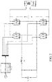
- Figs. 1 to 3 show a connecting manner of a vehicle-mounted charger of an electric vehicle according to an embodiment of the present invention.
- the vehicle-mounted charger of an electric vehicle according to embodiments of the present invention includes an H bridge.
- the H bridge includes a first switch tube T1, a second switch tube T2, a third switch tube T3 and a fourth switch tube T4.
- first inductor L1 includes a first inductor L1 and a second inductor L2, in which a first end of the first inductor L1 is connected to one end of a load or an anode end of an alternating current power grid AC, and a first end of the second inductor L2 is connected to the other end of the load or a cathode end of the alternating current power grid AC, and a second end of the first inductor L1 and a second end of the second inductor L2 are connected to the H bridge.
- the vehicle-mounted charger of an electric vehicle as shown in Fig.
- the vehicle-mounted charger of an electric vehicle as shown in Fig. 3 merely includes an inductor, for example, the first inductor LI, in which a first end of the first inductor L1 is connected to the other end of the load or a cathode end of the alternating current power grid AC, and a second end of the first inductor L1 is connected to the H bridge.
- Fig. 4 is a flow chart of a method for controlling a vehicle-mounted charger of an electric vehicle according to an embodiment of the present invention. As shown in Fig. 4 , the method for controlling a vehicle-mounted charger of an electric vehicle in an embodiment of the present invention includes the following.
- a first total discharging time TC for controlling the H bridge in a first manner and a second total discharging time TD for controlling the H bridge in a second manner are obtained, when the power battery discharges via the vehicle-mounted charger.
- the H bridge is controlled in the first manner A, and when an outward discharging transient voltage value of the vehicle-mounted charger is smaller than 0, the first switch tube T1 is controlled to be ON, the second switch tube T2 is controlled to be OFF, and the third switch tube T3 and the fourth switch tube T4 are controlled to be ON and OFF complementarily and alternately.
- the PWM waveform of the third switch tube T3 and the PWM waveform of the fourth switch tube T4 are controlled to be complementary with each other, and a duty ratio of the PWM waveform of the third switch tube T3 is controlled from large to small and then to large, and a duty ratio of the PWM waveform of the fourth switch tube T4 is controlled from small to large and then to small; when the outward discharging transient voltage value of the vehicle-mounted charger is larger than 0, the third switch tube T3 is controlled to be ON, the fourth switch tube T4 is controlled to be OFF, and the first switch tube T1 and the second switch tube T2 are controlled to be ON and OFF complementarily and alternately.
- the PWM waveform of the first switch tube T1 and the PWM waveform of the second switch tube T2 are controlled to be complementary with each other, and a duty ratio of the PWM waveform of the first switch tube T1 is controlled from large to small and then to large, and a duty ratio of the PWM waveform of the second switch tube T2 is controlled from small to large and then to small.
- the H bridge is controlled in the second manner B, and when an outward discharging transient voltage value of the vehicle-mounted charger is larger than 0, the second switch tube T2 is controlled to be ON, the first switch tube T1 is controlled to be OFF, and the third switch tube T3 and the fourth switch tube T4 are controlled to be ON and OFF complementarily and alternately.
- the PWM waveform of the third switch tube T3 and the PWM waveform of the fourth switch tube T4 are controlled to be complementary with each other, and a duty ratio of the PWM waveform of the third switch tube T3 is controlled from small to large and then to small, and a duty ratio of the PWM waveform of the fourth switch tube T4 is controlled from large to small and then to large; when the outward discharging transient voltage value of the
- the fourth switch tube T4 is controlled to be ON
- the third switch tube T3 is controlled to be OFF
- the first switch tube T1 and the second switch tube T2 are controlled to be ON and OFF complementarily and alternately.
- the PWM waveform of the first switch tube T1 and the PWM waveform of the second switch tube T2 are controlled to be complementary with each other, and a duty ratio of the PWM waveform of the first switch tube T1 is controlled from small to large and then to small, and a duty ratio of the PWM waveform of the second switch tube T2 is controlled from large to small and then to large.
- a first discharging predetermined time Tm for controlling the H bridge in the first manner and a second discharging predetermined time Tn for controlling the H bridge in the second manner are obtained.
- a manner for controlling the H bridge is selected according to a relation between the first total discharging time TC and the second total discharging time TD.
- step S4 an alternate control on the H bridge in the first manner or the second manner is performed according to the first discharging predetermined time Tm and the second discharging predetermined time Tn, so as to perform the temperature balanced control over the first switch tube, the second switch tube, the third switch tube and the fourth switch tube.
- the first discharging predetermined time Tm and the second discharging predetermined time Tn are preset for each discharging cycle of a discharging process of the power battery.
- the H bridge is only controlled by using the second manner B, when the outward discharging transient voltage value is larger than 0, the first switch tube T1 is kept OFF always, the second switch tube T2 is kept ON always, and the third switch tube T3 and fourth switch tube T4 are ON and OFF alternately and complementarily, and the inductor in the vehicle-mounted charger is charged when the fourth switch tube T4 is OFF and the third switch tube T3 is ON, and discharges when the fourth switch tube T4 is ON and the third switch tube T3 is OFF; when the outward discharging transient voltage value is smaller than 0, the fourth switch tube T4 is kept ON always, the third switch tube T3 is kept OFF always, and the first switch tube T1 and second switch tube T2 are ON and OFF alternately and complementarily, and the inductor in the vehicle-mounted charger is charged when the second switch tube T2 is OFF and the first switch tube T1 is ON, and discharges when
- the inductor Since the inductor is charged when the first tube T1 and the third tube T3 are ON, the first switch tube T1 and the third switch tube T3 are OFF with current, and hard switching is performed, therefore, the first switch tube T1 and the third switch tube T3 are overheated.
- the H bridge when the H bridge is controlled by using the first manner A to enable to discharge from the power battery via the vehicle-mounted charger, the time that the H bridge is controlled in the first manner A is recorded, thus the first total discharging time TC of controlling the H bridge in the first manner A is obtained, and then is stored; when the H bridge is controlled by using the second manner B enable to discharge from the power battery via the vehicle-mounted charger, the time that the H bridge is controlled in the second manner B is recorded, thus the second total discharging time TD of controlling the H bridge in the second manner B is obtained, and then is stored.
- the relation between the first total discharging time TC and the second total discharging time TD is determined.
- the manner of controlling the H bridge is selected when the power battery discharges via the vehicle-mounted charger according to the relation between the first total discharging time TC and the second total discharging time TD, thereby realizing the temperature balanced control over the first switch tube, the second switch tube, the third switch tube and the fourth switch tube.
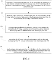
- Fig. 5 is a flow chart of a method for controlling a vehicle-mounted charger of an electric vehicle according to another embodiment of the present invention.
- step S3 further includes followings.
- the manner from the first manner and the second manner for controlling the H bridge is selected according to the relation between the first total discharging time TC and the second total discharging time TD.
- the H bridge is controlled in the selected manner, until the first total discharging time TC is equal to the second total discharging time TD.
- selecting the manner of controlling the H bridge according to the relation between the first total discharging time TC and the second total discharging time TD includes: if the first total discharging time TC is larger than the second total discharging time TD, the second manner B for controlling the H bridge is selected when the power battery discharges via the vehicle-mounted charger, and then the H bridge is controlled in the second manner B until the first total discharging time TC is equal to the second total discharging time TD, and then the alternate control is performed on the H bridge according to the first discharging predetermined time Tm and the second discharging predetermined time Tn; if the second total discharging time TD is larger than the first total discharging time TC, the first manner A for controlling the H bridge is selected when the power battery discharges via the vehicle-mounted charger, and then the H bridge is controlled in the first manner A until the first total discharging time TC is equal to the second total discharging time TD, and then the alternate control is performed on the H bridge
- the alternate control on the H bridge is performed according to the first discharging predetermined time Tm and the second discharging predetermined time Tn when the power battery discharges via the vehicle-mounted charger includes: when a time of controlling the H bridge in the first manner A reaches the first discharging predetermined time Tm, the H bridge in the second manner B is controlled till a time of controlling the H bridge in the second manner B reaches the second discharging predetermined time Tn; or when a time of controlling the H bridge in the second manner B reaches the second discharging predetermined time Tn, the H bridge in the first manner A is controlled till a time of controlling the H bridge in the first manner A reaches the first discharging predetermined time Tm.
- the first total discharging time TC that the H bridge is controlled in the first manner A as well as the second total discharging time TD that the H bridge is controlled in the second manner B are obtained from a storage region.
- the first discharging predetermined time Tm and the second discharging predetermined time Tn are preset. Then the relation between the first total discharging time TC and the second total discharging time TD is determined, the first manner A for controlling the H bridge firstly or the second manner B for controlling the H bridge firstly is determined according the relation.
- the first total discharging time TC and the second total discharging time TD are obtained from the storage region, an aim to determine the relation between the first total discharging time TC and the second total discharging time TD is to determine the selected manner for controlling the H bridge firstly when the power battery discharges via the vehicle-mounted charger.
- the H bridge is controlled by selecting the second manner B because the obtained time TC is greater than the obtained time TD, so as to enable to discharge from the power battery via the vehicle-mounted charger.
- the H bridge is switched to be controlled by using the first manner A, so as to discharge from the power battery via the vehicle-mounted charger till the time that the H bridge is controlled in the first manner A reaches Tm, then the H bridge is switched to be controlled by using the second manner B till the time that the H bridge is controlled in the second manner B reaches Tn, thereby finishing one discharging cycle (i.e., the time of one discharging cycle equals to Tm+Tn); then the H bridge is switched to be controlled by using the first manner A to enable to discharge from the power battery via the vehicle-mounted charger till the time that the H bridge is controlled by using the first manner A reaches Tm, then the H bridge is switched to be controlled by using the second manner B to enable to discharge from the power battery via the vehicle-mounted charger till the time that the H bridge is controlled by using the second manner B reaches Tn, ..., and the like, thereby realizing the alternative control over the H bridge, and further performing the temperature balanced control over the first switch tube, the second switch tube, the third switch
- the H bridge is controlled by selecting the first manner A because the obtained time TD is greater than the obtained time TC, so as to enable to discharge from the power battery via the vehicle-mounted charger.
- the H bridge is switched to be controlled by using the second manner B, so as to discharge from the power battery via the vehicle-mounted charger till the time that the H bridge is controlled by the second manner B reaches Tn, then the H bridge is switched to be controlled by using the first manner A till the time that the H bridge is controlled by the first manner A reaches Tm, thereby finishing one discharging cycle (i.e., the time of one discharging cycle equals to Tm+Tn); then the H bridge is switched to be controlled by using the second manner B to enable to discharge from the power battery via the vehicle-mounted charger till the time that the H bridge is controlled by using the second manner B reaches Tn, then the H bridge is switched to be controlled by using the first manner A to enable to discharge from the power battery via the vehicle-mounted charger till the time that the H bridge is controlled by using the first manner A reaches Tm, ..., and the like, thereby realizing the alternative control over the H bridge, and further performing the temperature balanced control over the first switch tube, the second switch tube, the third switch
- the H bridge can be controlled by selecting the first manner A to enable to discharge from the power battery via the vehicle-mounted charger till the time that the H bridge is controlled in the first manner A reaches Tm, then the H bridge is switched to be controlled by using the second manner B till the time that the H bridge is controlled in the second manner B reaches Tn, thereby finishing one discharging cycle (i.e., the time of one discharging cycle equals to Tm+Tn); then the H bridge is switched to be controlled by using the first manner A to enable to discharge from the power battery via the vehicle-mounted charger till the time that the H bridge is controlled by using the first manner A reaches Tm, then the H bridge is switched to be controlled by using the second manner B to enable to discharge from the power battery via the vehicle-mounted charger till the time that the H bridge is controlled by using the second manner B reaches Tn, ..., and the like, thereby realizing the alternative control
- the H bridge can be controlled by selecting the second manner B to enable to discharge from the power battery via the vehicle-mounted charger till the time that the H bridge is controlled by the second manner B reaches Tn, then the H bridge is switched to be controlled by using the first manner A till the time that the H bridge is controlled by the first manner A reaches Tm, thereby finishing one discharging cycle (i.e., the time of one discharging cycle equals to Tm+Tn); then the H bridge is switched to be controlled by using the second manner B to enable to discharge from the power battery via the vehicle-mounted charger till the time that the H bridge is controlled by using the second manner B reaches Tn, then the H bridge is switched to be controlled by using the first manner A to enable to discharge from the power battery via the vehicle-mounted charger till the time that the H bridge is controlled by using the first manner A reaches Tm, ..., and the like, thereby realizing the alternative control over the
- the H bridge is controlled to discharge from the power battery according to a fixed manner, i.e., the first or second manner, the total discharging time is recorded when the manner is switched, for example, when the H bridge is firstly controlled by using the first manner, the first total discharging time is recorded in this manner switching, and then the first total discharging time is obtained from the storage region when this discharging starts plus the discharging time recorded in the discharging cycle of this time.
- the first discharging predetermined time Tm that the H bridge is controlled in the first manner A is equal to the second discharging predetermined time Tn that the H bridge is controlled in the second manner B, thereby precisely controlling heating of the first switch tube T1, the second switch tube T2, the third switch tube T3 and the fourth switch tube T4 to be relatively balanced.
- the method for controlling a vehicle-mounted charger of an electric vehicle includes the following steps.
- a discharging wave is opened, i.e., when the power battery discharges via the vehicle-mounted charger, a control waveform needs to be output to control the switch tubes in the H bridge.
- a first total discharging time TC in the first manner A and a second total discharging time TD in the second manner B are obtained.
- a first discharging predetermined time Tm and a second discharging predetermined time Tn are set.
- step S504 it is judged whether the first total discharging time TC is larger than the second total discharging time TD, step S505 is executed if yes, and step S506 is executed if not.
- step S505 the second manner B is selected to control the H bridge till the first total discharging time TC is equal to the second total discharging time TD, then step S508 is executed.
- step S506 it is judged whether the first total discharging time TC is smaller than the second total discharging time TD, step S507 is executed if yes and step S508 or step S509 is executed if not.
- step S507 the first manner A is selected to control the H bridge till the first total discharging time TC is equal to the second total discharging time TD, then step S509 is executed.
- step S508 the first manner A is adopted to control the H bridge to enable to discharge from the power battery via the vehicle-mounted charger, then step S510 is executed.
- step S509 the second manner B is adopted to control the H bridge to enable to discharge from the power battery via the vehicle-mounted charger, then step S511 is executed.
- step S510 it is judged whether the time that the H bridge is controlled by using the first manner A reaches Tm, step S512 is executed if yes, and it is returned to step S508 if not.
- step S513 it is judged whether the time that the H bridge is controlled by using the second manner B reaches Tn, step S513 is executed if yes, and it is returned to step S509 if not.
- step S512 it is judged whether the discharging of this time ends during the discharging process, step S514 if yes and it is returned to continue to judge in step 509 if not.
- step S514 it is judged whether the discharging of this time ends during the discharging process, step S514 if yes and it is returned to continue to judge in step 508 if not.
- the heating of the first switch tube, the second switch tube, the third switch tube and the fourth switch tube is enabled to be relative balanced, and the service life of the vehicle-mounted charger is prolonged.
- the first total discharging time for controlling the H bridge in the first manner and the second total discharging time for controlling the H bridge in the second manner are obtained, and the first discharging predetermined time for controlling the H bridge in the first manner and the second discharging predetermined time for controlling the H bridge in the second manner are also obtained; and the manner from the first manner and the second manner for controlling the H bridge is selected according to the relation between the first total discharging time and the second total discharging time when the power battery discharges via the vehicle-mounted charger; finally, the alternate control on the H bridge in the first manner or the second manner is performed according to the first discharging predetermined time and the second discharging predetermined time, so as to perform the temperature balanced control over the first switch tube, the second switch tube, the third switch tube and the fourth switch tube, such that the heating of each switch tube is relatively balanced, the service life of the switch tubes in the
- a vehicle-mounted charger includes an H bridge and a controller such as an MCU (Micro Control Unit).
- the H bridge includes a first switch tube T1, a second switch tube T2, a third switch tube T3 and a fourth switch tube T4.
- the controller is configured to obtain a first total discharging time TC for controlling the H bridge in a first manner, and a second total discharging time TD for controlling the H bridge in a second manner when the power battery discharges via the vehicle-mounted charger; to obtain a first discharging predetermined time Tm for controlling the H bridge in the first manner and a second discharging predetermined time Tn for controlling the H bridge in the second manner; to select a manner for controlling the H bridge according to a relation between the first total discharging time TC and the second total discharging time TD; and to perform an alternate control on the H bridge in the first manner or the second manner according to the first discharging predetermined time Tm and the second discharging predetermined time Tn to perform temperature balanced control over the first switch tube, the second switch tube, the third switch tube and the fourth switch tube, in which the first discharging predetermined time Tm and the second discharging predetermined time Tn are preset for each discharging cycle of a discharging process of the power battery.
- the controller is configured to control the H bridge in the first manner A, such that when the power battery discharges via the vehicle-mounted charger, the time that the H bridge is controlled in the first manner A is recorded, thus the first total discharging time TC of controlling the H bridge in the first manner A is obtained, and then is stored;
- the controller is configured to control the H bridge in the second manner B, such that when the power battery discharges via the vehicle-mounted charger, the time that the H bridge is controlled in the second manner B is recorded, thus the second total discharging time TD of controlling the H bridge in the second manner B is obtained, and then is stored.
- the controller determines the relation between the first total discharging time TC and the second total discharging time TD every time.
- the manner of controlling the H bridge is selected according to the relation between the first total discharging time TC and the second total discharging time TD when the power battery discharges via the vehicle-mounted charger, thereby realizing the temperature balanced control over the first switch tube, the second switch tube, the third switch tube and the fourth switch tube.
- the controller is configured to select the manner from the first manner and the second manner for controlling the H bridge according to the relation between the first total discharging time TC and the second total discharging time TD; and control the H bridge in the selected manner, until the first total discharging time TC is equal to the second total discharging time TD.
- the controller is configured to select the manner of controlling the H bridge according to the relation between the first total discharging time TC and the second total discharging time TD by steps of: if the first total discharging time TC is larger than the second total discharging time TD, the second manner B for controlling the H bridge is selected when the power battery discharges via the vehicle-mounted charger, and then the H bridge is controlled in the second manner B until the first total discharging time TC is equal to the second total discharging time TD, and then the alternate control is performed on the H bridge according to the first discharging predetermined time Tm and the second discharging predetermined time Tn; if the second total discharging time TD is larger than the first total discharging time TC, the first manner A for controlling the H bridge is selected when the power battery discharges via the vehicle-mounted charger, and then the H bridge is controlled in the first manner A until the first total discharging time TC is equal to the second total discharging time TD, and then the alternate
- the controller is configured to perform the alternate control on the H bridge according to the first discharging predetermined time Tm and the second discharging predetermined time Tn when the power battery discharges via the vehicle-mounted charger by steps of: when a time of controlling the H bridge in the first manner A reaches the first discharging predetermined time Tm, controlling the H bridge in the second manner B till a time of controlling the H bridge in the second manner B reaches the second discharging predetermined time Tn; or when a time of controlling the H bridge in the second manner B reaches the second discharging predetermined time Tn, controlling the H bridge in the first manner A till a time of controlling the H bridge in the first manner A reaches the first discharging predetermined time Tm.
- the first total discharging time TC that the H bridge is controlled in the first manner A as well as the second total discharging time TD that the H bridge is controlled in the second manner B are obtained from a storage region.
- the first discharging predetermined time Tm and the second discharging predetermined time Tn are preset. Then the relation between the first total discharging time TC and the second total discharging time TD is determined, the first manner A for controlling the H bridge firstly or the second manner B for controlling the H bridge firstly is determined according the relation.
- the first total discharging time TC and the second total discharging time TD are obtained from the storage region, an aim to determine the relation between the first total discharging time TC and the second total discharging time TD is to determine the selected manner for controlling the H bridge firstly when the power battery discharges via the vehicle-mounted charger.
- the H bridge is controlled by selecting the second manner B because the obtained time TC is greater than the obtained time TD, so as to enable to discharge from the power battery via the vehicle-mounted charger.
- the H bridge is switched to be controlled by using the first manner A, so as to discharge from the power battery via the vehicle-mounted charger till the time that the H bridge is controlled in the first manner A reaches Tm, then the H bridge is switched to be controlled by using the second manner B till the time that the H bridge is controlled in the second manner B reaches Tn, thereby finishing one discharging cycle (i.e., the time of one discharging cycle equals to Tm+Tn); then the H bridge is switched to be controlled by using the first manner A to enable to discharge from the power battery via the vehicle-mounted charger till the time that the H bridge is controlled by using the first manner A reaches Tm, then the H bridge is switched to be controlled by using the second manner B to enable to discharge from the power battery via the vehicle-mounted charger till the time that the H bridge is controlled by using the second manner B reaches Tn, ..., and the like, thereby realizing the alternative control over the H bridge, and further performing the temperature balanced control over the first switch tube, the second switch tube, the third switch
- the H bridge is controlled by selecting the first manner A because the obtained time TD is greater than the obtained time TC, so as to enable to discharge from the power battery via the vehicle-mounted charger.
- the H bridge is switched to be controlled by using the second manner B, so as to discharge from the power battery via the vehicle-mounted charger till the time that the H bridge is controlled by the second manner B reaches Tn, then the H bridge is switched to be controlled by using the first manner A till the time that the H bridge is controlled by the first manner A reaches Tm, thereby finishing one discharging cycle (i.e., the time of one discharging cycle equals to Tm+Tn); then the H bridge is switched to be controlled by using the second manner B to enable to discharge from the power battery via the vehicle-mounted charger till the time that the H bridge is controlled by using the second manner B reaches Tn, then the H bridge is switched to be controlled by using the first manner A to enable to discharge from the power battery via the vehicle-mounted charger till the time that the H bridge is controlled by using the first manner A reaches Tm, ..., and the like, thereby realizing the alternative control over the H bridge, and further performing the temperature balanced control over the first switch tube, the second switch tube, the third switch
- the H bridge can be controlled by selecting the first manner A to enable to discharge from the power battery via the vehicle-mounted charger till the time that the H bridge is controlled in the first manner A reaches Tm, then the H bridge is switched to be controlled by using the second manner B till the time that the H bridge is controlled in the second manner B reaches Tn, thereby finishing one discharging cycle (i.e., the time of one discharging cycle equals to Tm+Tn); then the H bridge is switched to be controlled by using the first manner A to enable to discharge from the power battery via the vehicle-mounted charger till the time that the H bridge is controlled by using the first manner A reaches Tm, then the H bridge is switched to be controlled by using the second manner B to enable to discharge from the power battery via the vehicle-mounted charger till the time that the H bridge is controlled by using the second manner B reaches Tn, ..., and the like, thereby realizing the alternative control
- the H bridge can be controlled by selecting the second manner B to enable to discharge from the power battery via the vehicle-mounted charger till the time that the H bridge is controlled by the second manner B reaches Tn, then the H bridge is switched to be controlled by using the first manner A till the time that the H bridge is controlled by the first manner A reaches Tm, thereby finishing one discharging cycle (i.e., the time of one discharging cycle equals to Tm+Tn); then the H bridge is switched to be controlled by using the second manner B to enable to discharge from the power battery via the vehicle-mounted charger till the time that the H bridge is controlled by using the second manner B reaches Tn, then the H bridge is switched to be controlled by using the first manner A to enable to discharge from the power battery via the vehicle-mounted charger till the time that the H bridge is controlled by using the first manner A reaches Tm, ..., and the like, thereby realizing the alternative control over the
- the first discharging predetermined time Tm that the H bridge is controlled in the first manner A equals to the second discharging predetermined time Tn that the H bridge is controlled in the second manner B.
- the controller is configured to control the H bridge in the first manner A to discharge from the power battery, and when an outward discharging transient voltage value of the vehicle-mounted charger is smaller than 0, the first switch tube T1 is controlled to be ON, the second switch tube T2 is controlled to be OFF, and the third switch tube T3 and the fourth switch tube T4 are controlled to be ON and OFF complementarily and alternately.
- the PWM waveform of the third switch tube T3 and the PWM waveform of the fourth switch tube T4 are controlled to be complementary with each other, and a duty ratio of the PWM waveform of the third switch tube T3 is controlled from large to small and then to large, and a duty ratio of the PWM waveform of the fourth switch tube T4 is controlled from small to large and then to small; when the outward discharging transient voltage value of the vehicle-mounted charger is larger than 0, the third switch tube T3 is controlled to be ON, the fourth switch tube T4 is controlled to be OFF, and the first switch tube T1 and the second switch tube T2 are controlled to be ON and OFF complementarily and alternately.
- the PWM waveform of the first switch tube T1 and the PWM waveform of the second switch tube T2 are controlled to be complementary with each other, and a duty ratio of the PWM waveform of the first switch tube T1 is controlled from large to small and then to large, and a duty ratio of the PWM waveform of the second switch tube T2 is controlled from small to large and then to small.
- the controller when the controller is configured to control the H bridge in the second manner B, and when an outward discharging transient voltage value of the vehicle-mounted charger is larger than 0, the second switch tube T2 is controlled to be ON, the first switch tube T1 is controlled to be OFF, and the third switch tube T3 and the fourt switch tube T4 are controlled to be ON and OFF complementarily and alternately.
- the PWM waveform of the third switch tube T3 and the PWM waveform of the fourth switch tube T4 are controlled to be complementary with each other, and a duty ratio of the PWM waveform of the third switch tube T3 is controlled from small to large and then to small, and a duty ratio of the PWM waveform of the fourth switch tube T4 is controlled from large to small and then to large; when the outward discharging transient voltage value of the vehicle-mounted charger is smaller than 0, the fourth switch tube T4 is controlled to be ON, the third switch tube T3 is controlled to be OFF, and the first switch tube T1 and the second switch tube T2 are controlled to be ON and OFF complementarily and alternately.
- the PWM waveform of the first switch tube T1 and the PWM waveform of the second switch tube T2 are controlled to be complementary with each other, and a duty ratio of the PWM waveform of the first switch tube T1 is controlled from small to large and then to small, and a duty ratio of the PWM waveform of the second switch tube T2 is controlled from large to small and then to large.
- the first switch tube T1, the second switch tube T2, the third switch tube T3 and the fourth switch tube T4 are all IGBTs (Insulated Gate Bipolar Transistors), certainly, in other embodiments of the present invention, the first switch tube T1, the second switch tube T2, the third switch tube T3 and the fourth switch tube T4 can also be MOSs (Metal Oxide Semiconductors).
- the first discharging predetermined time Tm and the second discharging predetermined time Tn are preset for each discharging cycle of a discharging process of the power battery, so as to perform the temperature balanced control over the first switch tube, the second switch tube, the third switch tube and the fourth switch tube.
- the controller when the power battery discharges via the vehicle-mounted charger every time, the controller is configured to obtain the first total discharging time for controlling the H bridge in the first manner and the second total discharging time for controlling the H bridge in the second manner, to obtain the first discharging predetermined time for controlling the H bridge in the first manner and the second discharging predetermined time for controlling the H bridge in the second manner; and to select the manner from the first manner and the second manner for controlling the H bridge according to the relation between the first total discharging time and the second total discharging time, finally, to perform the alternate control on the H bridge in the first manner or the second manner according to the first discharging predetermined time and the second discharging predetermined time, so as to perform temperature balanced control over the first switch tube, the second switch tube, the third switch tube and the fourth switch tube, such that the heating of each switch tube is relatively balanced, the service life of the switch tubes in the H bridge is prolonged, and thus the service time is prolonged.
- embodiments of the present invention also provide an electric vehicle, including the above vehicle-mounted charger of an electric vehicle.
- the temperature balanced control over the first switch tube, the second switch tube, the third switch tube and the fourth switch tube in the H bridge can be realized, such that the heating of each switch tube is balanced, the service life of the switch tubes in the H bridge is prolonged, and thus the service time of the vehicle-mounted charger is prolonged.
- first and second merely aim to describe rather than being understood as indication or implication of relative importance or impliedly indicating a number of the indicated technical features. Therefore, the characteristics defined by “first” and “second” can clearly or impliedly comprise at least one such characteristic. In the description of the present invention, “more” means at least two, for example, two, three, etc., unless otherwise clearly specifically defined.
- the terms “mounted”, “jointed”, “connected”, “fixed”, etc. should be generalized understood, for example, the “connected” can be fixedly connected, or detachably connected, or integrated, can be mechanically connected or electrically connected, can also be directly connected or connected by an intermediate medium, and can also be internally communicated of two elements, or interacted of two elements, unless otherwise clearly defined.
- the terms “connected” can be fixedly connected, or detachably connected, or integrated, can be mechanically connected or electrically connected, can also be directly connected or connected by an intermediate medium, and can also be internally communicated of two elements, or interacted of two elements, unless otherwise clearly defined.
- the case that a first characteristic is "on” or “under” a second characteristic can be the case that the first characteristic and the second characteristic are in direct contact, or in indirect contact by an intermediate medium.
- the case that the first characteristic is "on”, “above” and “over” the second characteristic can be the case that the first characteristic is right or obliquely above the second characteristic, or only represents that the horizontal height of the first characteristic is higher than that of the second characteristic.
- the case that the first characteristic is "under”, “below” and “beneath” the second characteristic can be the case that the first characteristic is right or obliquely below the second characteristic, or only represents that the horizontal height of the first characteristic is lower than that of the second characteristic.
- the description of the reference terms “one embodiment”, “some embodiments”, “examples”, “specific examples” or “some examples” refers to the fact that the specific characteristic, structure, material or feature described in combination with the embodiment or example is contained in the at least one embodiment or example of the present invention.
- the schematic expression of the above terms unnecessarily aims at the same embodiment or example.
- the described specific characteristic, structure, material or feature can be combined in a proper manner in any one or more embodiments or examples.
- those skilled in the art can integrate or combine different embodiments or examples or the characteristics of different embodiments or examples described in the present specification.
Landscapes
- Engineering & Computer Science (AREA)
- Power Engineering (AREA)
- Transportation (AREA)
- Mechanical Engineering (AREA)
- Life Sciences & Earth Sciences (AREA)
- Sustainable Development (AREA)
- Sustainable Energy (AREA)
- Charge And Discharge Circuits For Batteries Or The Like (AREA)
- Electric Propulsion And Braking For Vehicles (AREA)
- Rectifiers (AREA)
Claims (5)
- Verfahren zum Steuern eines fahrzeugmontierbaren Ladegeräts eines Elektrofahrzeugs, wobei das fahrzeugmontierbare Ladegerät eine H-Brücke aufweist, die H-Brücke eine erste Schaltröhre, eine zweite Schaltröhre, eine dritte Schaltröhre und eine vierte Schaltröhre aufweist, und das Verfahren folgendes umfasst:Erhalten einer ersten Gesamtentladungszeit (TC) zum Steuern der H-Brücke auf eine erste Art und Weise und einer zweiten Gesamtentladungszeit (TD) zum Steuern der H-Brücke auf eine zweite Art und Weise, wenn eine Ladebatterie beginnt, sich über das fahrzeugmontierbare Ladegerät zu entladen;Erhalten einer ersten vorbestimmten Entladungszeit (Tm) zum Steuern der H-Brücke auf die erste Art und Weise und einer zweiten vorbestimmten Entladungszeit (Tn) zum Steuern der H-Brücke auf die zweite Art und Weise;Auswählen einer Art und Weise zum Steuern der H-Brücke gemäß einer Beziehung zwischen der ersten Gesamtentladungszeit (TC) und der zweiten Gesamtentladungszeit (TD);Steuern der H-Brücke in der gewählten Art und Weise, bis die erste Gesamtentladungszeit (TC) gleich der zweiten Gesamtentladungszeit (TD) ist, und Durchführen einer abwechselnden Steuerung der H-Brücke auf die erste oder die zweite Art und Weise gemäß der ersten vorbestimmten Entladungszeit (Tm) und der zweiten vorbestimmten Entladungszeit (Tn), um eine temperaturausgeglichene Steuerung über die erste Schaltröhre, die zweite Schaltröhre, die dritte Schaltröhre und die vierte Schaltröhre durchzuführen;wobei die erste vorbestimmte Entladungszeit (Tm) und die zweite vorbestimmte Entladungszeit (Tn) für jeden Entladungszyklus eines Entladungsvorgangs der Ladebatterie voreingestellt sind,dadurch gekennzeichnet, dassdas Auswählen der Art und Weise aus der ersten Art und Weise und der zweiten Art und Weise zur Steuerung der H-Brücke entsprechend dem Verhältnis zwischen der ersten Gesamtentladungszeit (TC) und der zweiten Gesamtentladungszeit (TD) folgendes umfasst:Auswählen der zweiten Art und Weise zum Steuern der H-Brücke, wenn die erste Gesamtentladungszeit (TC) größer als die zweite Gesamtentladungszeit (TD) ist;Auswählen der ersten Art und Weise zum Steuern der H-Brücke, wenn die erste Gesamtentladungszeit (TC) kleiner als die zweite Gesamtentladungszeit (TD) ist; undAuswählen der ersten Art und Weise zur Steuerung der H-Brücke, wenn die erste Gesamtentladungszeit (TC) gleich der zweiten Gesamtentladungszeit (TD) ist,ferner dadurch gekennzeichnet, dassdas Durchführen einer abwechselnden Steuerung der H-Brücke auf die erste Art und Weise oder die zweite Art und Weise gemäß der ersten vorgegebenen Entladungszeit (Tm) und der zweiten vorgegebenen Entladungszeit (Tn) folgendes umfasst:Steuern der H-Brücke auf die erste Art und Weise, bis eine Zeit des Steuerns der H-Brücke auf die erste Art und Weise die erste vorbestimmte Entladungszeit (Tm) erreicht, und Steuern der H-Brücke auf die zweite Art und Weise, bis eine Zeit des Steuerns der H-Brücke auf die zweite Art und Weise die zweite vorbestimmte Entladungszeit (Tn) erreicht; oderSteuern der H-Brücke auf die zweite Art und Weise, bis eine Zeit der Steuerung der H-Brücke auf die zweite Art und Weise die zweite vorbestimmte Entladungszeit (Tn) erreicht, und Steuern der H-Brücke auf die erste Art und Weise, bis eine Zeit der Steuerung der H-Brücke auf die erste Art und Weise die erste vorbestimmte Entladungszeit (Tm) erreicht,wobei das Steuern der H-Brücke auf die erste Art und Weise folgendes umfasst:wenn ein nach außen entladender transienter Spannungswert des fahrzeugmontierbaren Ladegeräts kleiner als 0 ist, Steuern der ersten Schaltröhre, so dass sie EIN ist, Steuern der zweiten Schaltröhre, so dass sie AUS ist, und Steuern der dritten Schaltröhre und der vierten Schaltröhre, so dass sie abwechselnd und komplementär EIN und AUS sind; undwenn der Wert der nach außen entladenden transienten Spannung des fahrzeugmontierbaren Ladegeräts größer als 0 ist, Steuern der dritten Schaltröhre, so dass sie EIN ist, der vierten Schaltröhre, so dass sie AUS ist, und der ersten Schaltröhre und der zweiten Schaltröhre, so dass sie abwechselnd und komplementär EIN und AUS sind,wobei das Steuern der H-Brücke auf die zweite Weise folgendes umfasst:wenn ein Wert der nach außen entladenden transienten Spannung des fahrzeugmontierbaren Ladegeräts größer als 0 ist, Steuern der zweiten Schaltröhre, so dass sie EIN ist, Steuern der ersten Schaltröhre, so dass sie AUS ist, und Steuern der dritten Schaltröhre und der vierten Schaltröhre, so dass sie abwechselnd und komplementär EIN und AUS sind; undwenn der Wert der nach außen entladenden transienten Spannung des fahrzeugmontierbaren Ladegeräts kleiner als 0 ist, Steuern der vierten Schaltröhre, so dass sie EIN ist, der dritten Schaltröhre, so dass sie EIN ist und der ersten Schaltröhre und der zweiten Schaltröhre, so dass sie abwechselnd und komplementär EIN und AUS sind.
- Verfahren nach Anspruch 1, wobei die erste vorbestimmte Entladungszeit (Tm) gleich der zweiten vorbestimmten Entladungszeit (Tn) ist.
- Fahrzeugmontierbares Ladegerät eines Elektrofahrzeugs, das folgendes aufweist:eine H-Brücke, umfassend eine erste Schaltröhre, eine zweite Schaltröhre, eine dritte Schaltröhre und eine vierte Schaltröhre; undeinen Controller, der konfiguriert ist, um eine erste Gesamtentladungszeit (TC) zur Steuerung der H-Brücke auf eine erste Art und Weise und eine zweite Gesamtentladungszeit (TD) zur Steuerung der H-Brücke auf eine zweite Art und Weise zu erhalten, wenn sich eine Ladebatterie über das fahrzeugmontierbare Ladegerät zu entladen beginnt; um eine erste vorbestimmte Entladungszeit (Tm) zum Steuern der H-Brücke auf die erste Art und Weise und eine zweite vorbestimmte Entladungszeit (Tn) zum Steuern der H-Brücke auf die zweite Art und Weise zu erhalten; um eine Art und Weise zum Steuern der H-Brücke gemäß einer Beziehung zwischen der ersten Gesamtentladungszeit (TC) und der zweiten Gesamtentladungszeit (TD) auszuwählen, undum die H-Brücke in der gewählten Art und Weise zu steuern, bis die erste Gesamtentladungszeit (TC) gleich der zweiten Gesamtentladungszeit (TD) ist; undum eine abwechselnde Steuerung der H-Brücke in der ersten Weise oder in der zweiten Weise gemäß der ersten vorbestimmten Entladungszeit (Tm) und der zweiten vorbestimmten Entladungszeit (Tn) durchzuführen, um eine temperaturausgeglichene Steuerung über die erste Schaltröhre, die zweite Schaltröhre, die dritte Schaltröhre und die vierte Schaltröhre durchzuführen;wobei die erste vorbestimmte Entladungszeit (Tm) und die zweite vorbestimmte Entladungszeit (Tn) für jeden Entladungszyklus eines Entladungsvorgangs der Ladebatterie voreingestellt sind,wobei der Controller weiterhin konfiguriert ist um:die zweite Art und Weise zur Steuerung der H-Brücke auszuwählen, wenn die erste Gesamtentladungszeit (TC) größer als die zweite Gesamtentladungszeit (TD) ist; die erste Art und Weise zum Steuern der H-Brücke auszuwählen, wenn die erste Gesamtentladungszeit (TC) kleiner als die zweite Gesamtentladungszeit (TD) ist; unddie erste Art und Weise zur Steuerung der H-Brücke auszuwählen, wenn die erste Gesamtentladungszeit (TC) gleich der zweiten Gesamtentladungszeit (TD) ist,wobei der Controller konfiguriert ist um:die H-Brücke auf die erste Art und Weise zu steuern, bis eine Zeit der Steuerung der H-Brücke auf die erste Art und Weise die erste vorbestimmte Entladungszeit (Tm) erreicht, und die H-Brücke auf die zweite Art und Weise zu steuern, bis eine Zeit der Steuerung der H-Brücke auf die zweite Art und Weise die zweite vorbestimmte Entladungszeit (Tn) erreicht; oderdie H-Brücke auf die zweite Art und Weise zu steuern, bis eine Zeit der Steuerung der H-Brücke auf die zweite Art und Weise die zweite vorbestimmte Entladungszeit (Tn) erreicht, und die H-Brücke auf die erste Art und Weise zu steuern, bis eine Zeit der Steuerung der H-Brücke auf die erste Art und Weise die erste vorbestimmte Entladungszeit (Tm) erreicht,wobei das Steuern der H-Brücke auf die erste Art und Weise umfasst:wenn ein Wert der nach außen entladenden transienten Spannung des fahrzeugmontierbaren Ladegeräts kleiner als 0 ist, Steuern der ersten Schaltröhre, so dass sie EIN ist, Steuern der zweiten Schaltröhre, so dass sie AUS ist, undSteuern der dritten Schaltröhre und der vierten Schaltröhre, so dass sie abwechselnd und komplementär EIN und AUS sind; undwenn der Wert der nach außen entladenden transienten Spannung des fahrzeugmontierbaren Ladegeräts größer als 0 ist, Steuern der dritte Schaltröhre, so dass sie EIN ist, der vierten Schaltröhre, so dass sie AUS ist, und der ersten Schaltröhre und der zweiten Schaltröhre, so dass sie abwechselnd und komplementär EIN und AUS sind,wobei die Steuerung der H-Brücke auf die zweite Weise folgendes umfasst:wenn ein Wert der nach außen entladenden transienten Spannung des fahrzeugmontierbaren Ladegeräts größer als 0 ist, Steuern der zweiten Schaltröhre, so dass sie EIN ist, Steuern der ersten Schaltröhre, so dass sie AUS ist, und Steuern der dritten Schaltröhre und der vierten Schaltröhre, so dass sie abwechselnd und komplementär EIN und AUS sind; undwenn der Wert der nach außen entladenden transienten Spannung des fahrzeugmontierbaren Ladegeräts kleiner als 0 ist, Steuern der vierten Schaltröhre, so dass sie EIN ist, der dritten Schaltröhre, so dass sie AUS ist, und der ersten Schaltröhre und der zweiten Schaltröhre, so dass sie abwechselnd und komplementär EIN und AUS sind.
- Fahrzeugmontierbares Ladegerät nach Anspruch 3, wobei die erste vorbestimmte Entladungszeit (Tm) gleich der zweiten vorbestimmten Entladungszeit (Tn) ist.
- Elektrofahrzeug, das das fahrzeugmontierbare Ladegerät eines Elektrofahrzeugs nach einem der Ansprüche 3 bis 4 aufweist.
Applications Claiming Priority (2)
| Application Number | Priority Date | Filing Date | Title |
|---|---|---|---|
| CN201510956679.6A CN106891745B (zh) | 2015-12-18 | 2015-12-18 | 电动汽车及其车载充电器和车载充电器的控制方法 |
| PCT/CN2016/110269 WO2017101836A1 (en) | 2015-12-18 | 2016-12-16 | Electric vehicle and vehicle-mounted charger and method for controlling the same |
Publications (3)
| Publication Number | Publication Date |
|---|---|
| EP3390141A1 EP3390141A1 (de) | 2018-10-24 |
| EP3390141A4 EP3390141A4 (de) | 2019-01-02 |
| EP3390141B1 true EP3390141B1 (de) | 2020-12-02 |
Family
ID=59055755
Family Applications (1)
| Application Number | Title | Priority Date | Filing Date |
|---|---|---|---|
| EP16874893.7A Active EP3390141B1 (de) | 2015-12-18 | 2016-12-16 | Elektrofahrzeug und fahrzeugmontiertes ladegerät und verfahren zur steuerung davon |
Country Status (6)
| Country | Link |
|---|---|
| US (1) | US10625616B2 (de) |
| EP (1) | EP3390141B1 (de) |
| JP (1) | JP6596161B2 (de) |
| KR (1) | KR102192992B1 (de) |
| CN (1) | CN106891745B (de) |
| WO (1) | WO2017101836A1 (de) |
Families Citing this family (4)
| Publication number | Priority date | Publication date | Assignee | Title |
|---|---|---|---|---|
| CN106891736B (zh) * | 2015-12-18 | 2019-06-21 | 比亚迪股份有限公司 | 电动汽车及其车载充电器和车载充电器的控制方法 |
| CN106891744B (zh) * | 2015-12-18 | 2019-11-08 | 比亚迪股份有限公司 | 电动汽车及其车载充电器和车载充电器的控制方法 |
| CN106891748B (zh) * | 2015-12-18 | 2019-02-26 | 比亚迪股份有限公司 | 电动汽车及其车载充电器和车载充电器的控制方法 |
| CN108155802B (zh) * | 2016-12-02 | 2020-03-31 | 比亚迪股份有限公司 | 电动汽车及其dc-dc变换器和dc-dc变换器的控制方法 |
Family Cites Families (27)
| Publication number | Priority date | Publication date | Assignee | Title |
|---|---|---|---|---|
| JP3484251B2 (ja) | 1995-02-06 | 2004-01-06 | 本田技研工業株式会社 | 電気自動車用蓄電池充電制御装置 |
| GB2414120B (en) * | 2004-05-11 | 2008-04-02 | Splashpower Ltd | Controlling inductive power transfer systems |
| JP2007129868A (ja) * | 2005-11-07 | 2007-05-24 | Hanshin Electric Co Ltd | 突入電流抑制回路制御方法および突入電流抑制回路制御装置 |
| JP4961830B2 (ja) * | 2006-05-15 | 2012-06-27 | トヨタ自動車株式会社 | 蓄電装置の充放電制御装置および充放電制御方法ならびに電動車両 |
| JP2009027815A (ja) * | 2007-07-18 | 2009-02-05 | Fuji Heavy Ind Ltd | 系統連系コンバータ装置 |
| JP2009159786A (ja) * | 2007-12-27 | 2009-07-16 | Toyota Industries Corp | 電力変換装置 |
| JP4285578B1 (ja) * | 2008-01-15 | 2009-06-24 | トヨタ自動車株式会社 | 車両の充電装置 |
| JP5563577B2 (ja) * | 2008-09-11 | 2014-07-30 | イートレックス・インコーポレーテッド | 双方向インバータ・チャージャ及びインバータ・チャージャ装置 |
| CN101604923B (zh) * | 2009-07-13 | 2012-05-16 | 西安理工大学 | 用于单相并网逆变器的脉冲宽度调制pwm控制方法 |
| KR101192444B1 (ko) * | 2010-07-05 | 2012-10-18 | 정윤이 | 배터리 전원 공급 장치 및 그 전력 제어 방법 |
| JP5712584B2 (ja) * | 2010-12-03 | 2015-05-07 | 株式会社豊田自動織機 | 電源装置 |
| US9623761B2 (en) * | 2010-12-22 | 2017-04-18 | Ford Global Technologies, Llc | Vehicle and method for authenticating a charge station |
| JP5858217B2 (ja) * | 2011-08-23 | 2016-02-10 | 富士電機株式会社 | 交流−交流変換回路 |
| KR20130025822A (ko) * | 2011-09-02 | 2013-03-12 | 삼성에스디아이 주식회사 | 모터를 구비한 전기기기의 배터리 충전 장치 및 방법 |
| US8862414B2 (en) * | 2011-09-21 | 2014-10-14 | Tesla Motors, Inc. | Detection of high voltage electrolysis of coolant in a battery pack |
| CN202429065U (zh) * | 2011-12-30 | 2012-09-12 | 比亚迪股份有限公司 | 电动车辆及其驱动系统 |
| CN102684525B (zh) * | 2012-02-15 | 2016-03-09 | 华为技术有限公司 | 逆变器电路及逆变器电路的控制方法 |
| KR20140003082A (ko) * | 2012-06-29 | 2014-01-09 | 엘에스산전 주식회사 | 전기 자동차용 충전기 |
| US8751085B2 (en) * | 2012-08-03 | 2014-06-10 | Chrysler Group Llc | Method and system for battery charging and thermal management control in electrified vehicles |
| CN103259434B (zh) * | 2013-04-23 | 2015-04-29 | 盐城工学院 | 原边单相桥-副边三相桥高频链逆变器及其数字控制系统和方法 |
| EP3041122A4 (de) * | 2013-08-26 | 2016-09-14 | Panasonic Ip Man Co Ltd | Steuerschaltung, schaltkreis, leistungsumwandlungsvorrichtung, ladevorrichtung, fahrzeug und steuerungsverfahren |
| US9428173B2 (en) * | 2013-10-29 | 2016-08-30 | Toyota Motor Engineering & Manufacturing North America, Inc. | Vehicle battery pre-charge feature |
| JP6194841B2 (ja) * | 2014-04-07 | 2017-09-13 | 株式会社デンソー | 均等化放電装置 |
| JP6133817B2 (ja) | 2014-05-14 | 2017-05-24 | 本田技研工業株式会社 | 2電源システム及び電動車両 |
| CN103986377A (zh) | 2014-06-04 | 2014-08-13 | 国家电网公司 | 一种直流无刷电动机控制方法 |
| CN104600998A (zh) * | 2015-02-10 | 2015-05-06 | 四川英杰电气股份有限公司 | 一种开关电源开关器件均匀发热的控制方法 |
| CN204835609U (zh) | 2015-07-24 | 2015-12-02 | 比亚迪股份有限公司 | 电动汽车及电动汽车的车载充电器 |
-
2015
- 2015-12-18 CN CN201510956679.6A patent/CN106891745B/zh active Active
-
2016
- 2016-12-16 KR KR1020187015596A patent/KR102192992B1/ko active Active
- 2016-12-16 JP JP2018531181A patent/JP6596161B2/ja active Active
- 2016-12-16 US US16/062,383 patent/US10625616B2/en active Active
- 2016-12-16 EP EP16874893.7A patent/EP3390141B1/de active Active
- 2016-12-16 WO PCT/CN2016/110269 patent/WO2017101836A1/en not_active Ceased
Non-Patent Citations (1)
| Title |
|---|
| None * |
Also Published As
| Publication number | Publication date |
|---|---|
| CN106891745B (zh) | 2019-11-05 |
| CN106891745A (zh) | 2017-06-27 |
| US20180370381A1 (en) | 2018-12-27 |
| KR102192992B1 (ko) | 2020-12-21 |
| EP3390141A4 (de) | 2019-01-02 |
| KR20180078300A (ko) | 2018-07-09 |
| WO2017101836A1 (en) | 2017-06-22 |
| JP6596161B2 (ja) | 2019-10-23 |
| JP2019500840A (ja) | 2019-01-10 |
| EP3390141A1 (de) | 2018-10-24 |
| US10625616B2 (en) | 2020-04-21 |
Similar Documents
| Publication | Publication Date | Title |
|---|---|---|
| US10566821B2 (en) | Electric vehicle and vehicle-mounted charger, and method for controlling the same | |
| WO2017101841A1 (en) | Electric vehicle and vehicle-mounted charger and method for controlling the same | |
| EP3391500B1 (de) | Elektrofahrzeug und fahrzeugmontiertes ladegerät und verfahren zur steuerung davon | |
| EP3390141B1 (de) | Elektrofahrzeug und fahrzeugmontiertes ladegerät und verfahren zur steuerung davon | |
| WO2017101837A1 (en) | Electric vehicle and vehicle-mounted charger and method for controlling the same | |
| EP3390144B1 (de) | Elektrofahrzeug und fahrzeugmontiertes ladegerät und verfahren zur steuerung davon | |
| US10894477B2 (en) | Electric vehicle and vehicle-mounted charger, and method for controlling the same | |
| CN110001455B (zh) | 电动汽车及其车载充电器和车载充电器的控制方法 | |
| EP3390143B1 (de) | Elektrofahrzeug und fahrzeugmontiertes ladegerät und verfahren zur steuerung davon |
Legal Events
| Date | Code | Title | Description |
|---|---|---|---|
| STAA | Information on the status of an ep patent application or granted ep patent |
Free format text: STATUS: THE INTERNATIONAL PUBLICATION HAS BEEN MADE |
|
| PUAI | Public reference made under article 153(3) epc to a published international application that has entered the european phase |
Free format text: ORIGINAL CODE: 0009012 |
|
| STAA | Information on the status of an ep patent application or granted ep patent |
Free format text: STATUS: REQUEST FOR EXAMINATION WAS MADE |
|
| 17P | Request for examination filed |
Effective date: 20180718 |
|
| AK | Designated contracting states |
Kind code of ref document: A1 Designated state(s): AL AT BE BG CH CY CZ DE DK EE ES FI FR GB GR HR HU IE IS IT LI LT LU LV MC MK MT NL NO PL PT RO RS SE SI SK SM TR |
|
| AX | Request for extension of the european patent |
Extension state: BA ME |
|
| A4 | Supplementary search report drawn up and despatched |
Effective date: 20181203 |
|
| RIC1 | Information provided on ipc code assigned before grant |
Ipc: H02M 7/5387 20070101ALI20181126BHEP Ipc: B60L 11/18 20060101AFI20181126BHEP |
|
| DAV | Request for validation of the european patent (deleted) | ||
| DAX | Request for extension of the european patent (deleted) | ||
| REG | Reference to a national code |
Ref country code: DE Ref legal event code: R079 Ref document number: 602016049240 Country of ref document: DE Free format text: PREVIOUS MAIN CLASS: B60L0011180000 Ipc: B60L0050500000 |
|
| GRAP | Despatch of communication of intention to grant a patent |
Free format text: ORIGINAL CODE: EPIDOSNIGR1 |
|
| STAA | Information on the status of an ep patent application or granted ep patent |
Free format text: STATUS: GRANT OF PATENT IS INTENDED |
|
| RIC1 | Information provided on ipc code assigned before grant |
Ipc: B60L 50/50 20190101AFI20200527BHEP |
|
| INTG | Intention to grant announced |
Effective date: 20200626 |
|
| GRAS | Grant fee paid |
Free format text: ORIGINAL CODE: EPIDOSNIGR3 |
|
| GRAA | (expected) grant |
Free format text: ORIGINAL CODE: 0009210 |
|
| STAA | Information on the status of an ep patent application or granted ep patent |
Free format text: STATUS: THE PATENT HAS BEEN GRANTED |
|
| AK | Designated contracting states |
Kind code of ref document: B1 Designated state(s): AL AT BE BG CH CY CZ DE DK EE ES FI FR GB GR HR HU IE IS IT LI LT LU LV MC MK MT NL NO PL PT RO RS SE SI SK SM TR |
|
| REG | Reference to a national code |
Ref country code: GB Ref legal event code: FG4D |
|
| REG | Reference to a national code |
Ref country code: AT Ref legal event code: REF Ref document number: 1340548 Country of ref document: AT Kind code of ref document: T Effective date: 20201215 Ref country code: CH Ref legal event code: EP |
|
| REG | Reference to a national code |
Ref country code: IE Ref legal event code: FG4D |
|
| REG | Reference to a national code |
Ref country code: DE Ref legal event code: R096 Ref document number: 602016049240 Country of ref document: DE |
|
| REG | Reference to a national code |
Ref country code: NL Ref legal event code: FP |
|
| REG | Reference to a national code |
Ref country code: NO Ref legal event code: T2 Effective date: 20201202 |
|
| PG25 | Lapsed in a contracting state [announced via postgrant information from national office to epo] |
Ref country code: RS Free format text: LAPSE BECAUSE OF FAILURE TO SUBMIT A TRANSLATION OF THE DESCRIPTION OR TO PAY THE FEE WITHIN THE PRESCRIBED TIME-LIMIT Effective date: 20201202 Ref country code: GR Free format text: LAPSE BECAUSE OF FAILURE TO SUBMIT A TRANSLATION OF THE DESCRIPTION OR TO PAY THE FEE WITHIN THE PRESCRIBED TIME-LIMIT Effective date: 20210303 Ref country code: FI Free format text: LAPSE BECAUSE OF FAILURE TO SUBMIT A TRANSLATION OF THE DESCRIPTION OR TO PAY THE FEE WITHIN THE PRESCRIBED TIME-LIMIT Effective date: 20201202 |
|
| REG | Reference to a national code |
Ref country code: AT Ref legal event code: MK05 Ref document number: 1340548 Country of ref document: AT Kind code of ref document: T Effective date: 20201202 |
|
| PG25 | Lapsed in a contracting state [announced via postgrant information from national office to epo] |
Ref country code: SE Free format text: LAPSE BECAUSE OF FAILURE TO SUBMIT A TRANSLATION OF THE DESCRIPTION OR TO PAY THE FEE WITHIN THE PRESCRIBED TIME-LIMIT Effective date: 20201202 Ref country code: BG Free format text: LAPSE BECAUSE OF FAILURE TO SUBMIT A TRANSLATION OF THE DESCRIPTION OR TO PAY THE FEE WITHIN THE PRESCRIBED TIME-LIMIT Effective date: 20210302 Ref country code: PL Free format text: LAPSE BECAUSE OF FAILURE TO SUBMIT A TRANSLATION OF THE DESCRIPTION OR TO PAY THE FEE WITHIN THE PRESCRIBED TIME-LIMIT Effective date: 20201202 Ref country code: LV Free format text: LAPSE BECAUSE OF FAILURE TO SUBMIT A TRANSLATION OF THE DESCRIPTION OR TO PAY THE FEE WITHIN THE PRESCRIBED TIME-LIMIT Effective date: 20201202 |
|
| PG25 | Lapsed in a contracting state [announced via postgrant information from national office to epo] |
Ref country code: HR Free format text: LAPSE BECAUSE OF FAILURE TO SUBMIT A TRANSLATION OF THE DESCRIPTION OR TO PAY THE FEE WITHIN THE PRESCRIBED TIME-LIMIT Effective date: 20201202 |
|
| REG | Reference to a national code |
Ref country code: LT Ref legal event code: MG9D |
|
| PG25 | Lapsed in a contracting state [announced via postgrant information from national office to epo] |
Ref country code: RO Free format text: LAPSE BECAUSE OF FAILURE TO SUBMIT A TRANSLATION OF THE DESCRIPTION OR TO PAY THE FEE WITHIN THE PRESCRIBED TIME-LIMIT Effective date: 20201202 Ref country code: PT Free format text: LAPSE BECAUSE OF FAILURE TO SUBMIT A TRANSLATION OF THE DESCRIPTION OR TO PAY THE FEE WITHIN THE PRESCRIBED TIME-LIMIT Effective date: 20210405 Ref country code: SK Free format text: LAPSE BECAUSE OF FAILURE TO SUBMIT A TRANSLATION OF THE DESCRIPTION OR TO PAY THE FEE WITHIN THE PRESCRIBED TIME-LIMIT Effective date: 20201202 Ref country code: SM Free format text: LAPSE BECAUSE OF FAILURE TO SUBMIT A TRANSLATION OF THE DESCRIPTION OR TO PAY THE FEE WITHIN THE PRESCRIBED TIME-LIMIT Effective date: 20201202 Ref country code: LT Free format text: LAPSE BECAUSE OF FAILURE TO SUBMIT A TRANSLATION OF THE DESCRIPTION OR TO PAY THE FEE WITHIN THE PRESCRIBED TIME-LIMIT Effective date: 20201202 Ref country code: CZ Free format text: LAPSE BECAUSE OF FAILURE TO SUBMIT A TRANSLATION OF THE DESCRIPTION OR TO PAY THE FEE WITHIN THE PRESCRIBED TIME-LIMIT Effective date: 20201202 Ref country code: EE Free format text: LAPSE BECAUSE OF FAILURE TO SUBMIT A TRANSLATION OF THE DESCRIPTION OR TO PAY THE FEE WITHIN THE PRESCRIBED TIME-LIMIT Effective date: 20201202 |
|
| REG | Reference to a national code |
Ref country code: CH Ref legal event code: PL |
|
| PG25 | Lapsed in a contracting state [announced via postgrant information from national office to epo] |
Ref country code: AT Free format text: LAPSE BECAUSE OF FAILURE TO SUBMIT A TRANSLATION OF THE DESCRIPTION OR TO PAY THE FEE WITHIN THE PRESCRIBED TIME-LIMIT Effective date: 20201202 |
|
| REG | Reference to a national code |
Ref country code: DE Ref legal event code: R097 Ref document number: 602016049240 Country of ref document: DE Ref country code: BE Ref legal event code: MM Effective date: 20201231 |
|
| PG25 | Lapsed in a contracting state [announced via postgrant information from national office to epo] |
Ref country code: IS Free format text: LAPSE BECAUSE OF FAILURE TO SUBMIT A TRANSLATION OF THE DESCRIPTION OR TO PAY THE FEE WITHIN THE PRESCRIBED TIME-LIMIT Effective date: 20210402 Ref country code: MC Free format text: LAPSE BECAUSE OF FAILURE TO SUBMIT A TRANSLATION OF THE DESCRIPTION OR TO PAY THE FEE WITHIN THE PRESCRIBED TIME-LIMIT Effective date: 20201202 |
|
| PLBE | No opposition filed within time limit |
Free format text: ORIGINAL CODE: 0009261 |
|
| STAA | Information on the status of an ep patent application or granted ep patent |
Free format text: STATUS: NO OPPOSITION FILED WITHIN TIME LIMIT |
|
| PG25 | Lapsed in a contracting state [announced via postgrant information from national office to epo] |
Ref country code: LU Free format text: LAPSE BECAUSE OF NON-PAYMENT OF DUE FEES Effective date: 20201216 Ref country code: IT Free format text: LAPSE BECAUSE OF FAILURE TO SUBMIT A TRANSLATION OF THE DESCRIPTION OR TO PAY THE FEE WITHIN THE PRESCRIBED TIME-LIMIT Effective date: 20201202 Ref country code: AL Free format text: LAPSE BECAUSE OF FAILURE TO SUBMIT A TRANSLATION OF THE DESCRIPTION OR TO PAY THE FEE WITHIN THE PRESCRIBED TIME-LIMIT Effective date: 20201202 Ref country code: IE Free format text: LAPSE BECAUSE OF NON-PAYMENT OF DUE FEES Effective date: 20201216 |
|
| 26N | No opposition filed |
Effective date: 20210903 |
|
| PG25 | Lapsed in a contracting state [announced via postgrant information from national office to epo] |
Ref country code: SI Free format text: LAPSE BECAUSE OF FAILURE TO SUBMIT A TRANSLATION OF THE DESCRIPTION OR TO PAY THE FEE WITHIN THE PRESCRIBED TIME-LIMIT Effective date: 20201202 Ref country code: CH Free format text: LAPSE BECAUSE OF NON-PAYMENT OF DUE FEES Effective date: 20201231 Ref country code: DK Free format text: LAPSE BECAUSE OF FAILURE TO SUBMIT A TRANSLATION OF THE DESCRIPTION OR TO PAY THE FEE WITHIN THE PRESCRIBED TIME-LIMIT Effective date: 20201202 Ref country code: LI Free format text: LAPSE BECAUSE OF NON-PAYMENT OF DUE FEES Effective date: 20201231 |
|
| PG25 | Lapsed in a contracting state [announced via postgrant information from national office to epo] |
Ref country code: ES Free format text: LAPSE BECAUSE OF FAILURE TO SUBMIT A TRANSLATION OF THE DESCRIPTION OR TO PAY THE FEE WITHIN THE PRESCRIBED TIME-LIMIT Effective date: 20201202 |
|
| PG25 | Lapsed in a contracting state [announced via postgrant information from national office to epo] |
Ref country code: IS Free format text: LAPSE BECAUSE OF FAILURE TO SUBMIT A TRANSLATION OF THE DESCRIPTION OR TO PAY THE FEE WITHIN THE PRESCRIBED TIME-LIMIT Effective date: 20210402 Ref country code: TR Free format text: LAPSE BECAUSE OF FAILURE TO SUBMIT A TRANSLATION OF THE DESCRIPTION OR TO PAY THE FEE WITHIN THE PRESCRIBED TIME-LIMIT Effective date: 20201202 Ref country code: MT Free format text: LAPSE BECAUSE OF FAILURE TO SUBMIT A TRANSLATION OF THE DESCRIPTION OR TO PAY THE FEE WITHIN THE PRESCRIBED TIME-LIMIT Effective date: 20201202 Ref country code: CY Free format text: LAPSE BECAUSE OF FAILURE TO SUBMIT A TRANSLATION OF THE DESCRIPTION OR TO PAY THE FEE WITHIN THE PRESCRIBED TIME-LIMIT Effective date: 20201202 |
|
| PG25 | Lapsed in a contracting state [announced via postgrant information from national office to epo] |
Ref country code: MK Free format text: LAPSE BECAUSE OF FAILURE TO SUBMIT A TRANSLATION OF THE DESCRIPTION OR TO PAY THE FEE WITHIN THE PRESCRIBED TIME-LIMIT Effective date: 20201202 |
|
| PG25 | Lapsed in a contracting state [announced via postgrant information from national office to epo] |
Ref country code: BE Free format text: LAPSE BECAUSE OF NON-PAYMENT OF DUE FEES Effective date: 20201231 |
|
| P01 | Opt-out of the competence of the unified patent court (upc) registered |
Effective date: 20230527 |
|
| PGFP | Annual fee paid to national office [announced via postgrant information from national office to epo] |
Ref country code: GB Payment date: 20251218 Year of fee payment: 10 |
|
| PGFP | Annual fee paid to national office [announced via postgrant information from national office to epo] |
Ref country code: FR Payment date: 20251218 Year of fee payment: 10 Ref country code: NL Payment date: 20251219 Year of fee payment: 10 |
|
| PGFP | Annual fee paid to national office [announced via postgrant information from national office to epo] |
Ref country code: DE Payment date: 20251222 Year of fee payment: 10 Ref country code: NO Payment date: 20251230 Year of fee payment: 10 |