EP3390209B1 - Aerodynamische ablenkvorrichtung für kraftfahrzeugrad - Google Patents
Aerodynamische ablenkvorrichtung für kraftfahrzeugrad Download PDFInfo
- Publication number
- EP3390209B1 EP3390209B1 EP16806264.4A EP16806264A EP3390209B1 EP 3390209 B1 EP3390209 B1 EP 3390209B1 EP 16806264 A EP16806264 A EP 16806264A EP 3390209 B1 EP3390209 B1 EP 3390209B1
- Authority
- EP
- European Patent Office
- Prior art keywords
- wall
- deflecting wall
- support
- deflector
- deflecting
- Prior art date
- Legal status (The legal status is an assumption and is not a legal conclusion. Google has not performed a legal analysis and makes no representation as to the accuracy of the status listed.)
- Active
Links
Images


Classifications
-
- B—PERFORMING OPERATIONS; TRANSPORTING
- B62—LAND VEHICLES FOR TRAVELLING OTHERWISE THAN ON RAILS
- B62D—MOTOR VEHICLES; TRAILERS
- B62D35/00—Vehicle bodies characterised by streamlining
- B62D35/02—Streamlining the undersurfaces
-
- Y—GENERAL TAGGING OF NEW TECHNOLOGICAL DEVELOPMENTS; GENERAL TAGGING OF CROSS-SECTIONAL TECHNOLOGIES SPANNING OVER SEVERAL SECTIONS OF THE IPC; TECHNICAL SUBJECTS COVERED BY FORMER USPC CROSS-REFERENCE ART COLLECTIONS [XRACs] AND DIGESTS
- Y02—TECHNOLOGIES OR APPLICATIONS FOR MITIGATION OR ADAPTATION AGAINST CLIMATE CHANGE
- Y02T—CLIMATE CHANGE MITIGATION TECHNOLOGIES RELATED TO TRANSPORTATION
- Y02T10/00—Road transport of goods or passengers
- Y02T10/80—Technologies aiming to reduce greenhouse gasses emissions common to all road transportation technologies
- Y02T10/82—Elements for improving aerodynamics
-
- Y—GENERAL TAGGING OF NEW TECHNOLOGICAL DEVELOPMENTS; GENERAL TAGGING OF CROSS-SECTIONAL TECHNOLOGIES SPANNING OVER SEVERAL SECTIONS OF THE IPC; TECHNICAL SUBJECTS COVERED BY FORMER USPC CROSS-REFERENCE ART COLLECTIONS [XRACs] AND DIGESTS
- Y02—TECHNOLOGIES OR APPLICATIONS FOR MITIGATION OR ADAPTATION AGAINST CLIMATE CHANGE
- Y02T—CLIMATE CHANGE MITIGATION TECHNOLOGIES RELATED TO TRANSPORTATION
- Y02T10/00—Road transport of goods or passengers
- Y02T10/80—Technologies aiming to reduce greenhouse gasses emissions common to all road transportation technologies
- Y02T10/88—Optimized components or subsystems, e.g. lighting, actively controlled glasses
Definitions
- the invention relates to an aerodynamic deflector device for a motor vehicle wheel.
- a constant concern in the automotive field is fuel consumption and the ecological impact of the vehicle, particularly through its greenhouse gas emissions such as CO2 or toxic gases such as Nox for example.
- CO2 greenhouse gas emissions
- Nox toxic gases
- the aerodynamics of a motor vehicle is an important characteristic because it influences in particular the fuel consumption (and therefore the pollution) as well as the performance in particular of acceleration of said vehicle.
- the drag or the aerodynamic resistance to advancement plays a determining role, in particular at higher speeds, since the drag varies as a function of the square of the speed of movement of the vehicle.
- the reference surface used for a motor vehicle corresponds usually on its frontal surface. It is therefore understood that in order to reduce the drag, it is necessary to aim to reduce the reference surface.
- the wheels can significantly increase aerodynamic resistance, as they generate turbulence when the air flow hits the rotating wheel. At high speeds it has been shown that the front wheels can contribute up to 30% to the reference surface.
- the wheel arch is a cavity in the body of the vehicle, and surrounding a wheel (this corresponds to the fender of the vehicle).
- the wheel arch serves several functions. It limits in particular (by retaining them) the projections of water, mud or other materials on which the wheel is likely to circulate and which it may be required to expel during its rotation.
- the air reaching the wheel arch circulates in particular in the narrow space separating the wheel from the wheel arch. It is known that on this occasion, turbulence forms around the turns of the wheel and creates an aerodynamic brake.
- Such a deflector device is known from the document FR 2 858 793 A1 , which discloses the preamble of the first claim of the present application.
- the present invention aims to at least partially overcome some of the drawbacks described above by providing an aerodynamic deflector device equipped with an actuator, the size and power of which can be limited.
- the deflector wall has in cross section a central portion, in particular intended to be disposed in the mounted state of the device upstream of the wheel, and two lateral parts widening out from the central part so as to obtain a divergent shape in the direction of the air flow striking said wall.
- the actuator can thus have reduced size, power and consumption because the forces for moving the wall are minimized.
- the aerodynamic deflector device according to the invention may include one or more of the characteristics described below taken alone or in combination.
- the lateral parts of the deflector wall are curved.
- the lateral parts of the deflector wall are curved in a concave fashion.
- the lateral part of the deflector wall intended to be on the side of the engine compartment has a greater lateral extension than the other lateral part of the deflector wall.
- the central part of the deflector wall has, in longitudinal section, the shape of a circular arc.
- the deflector wall is connected to the support by means of a pivot axis and in that the actuator is coupled directly to this pivot axis.
- the deflector wall is connected to the support by means of pivot bearings and the actuator comprises an output lever having at its free end a pin cooperating with a displacement rail of the deflector wall.
- the displacement rail has an oblong hole into which penetrates the pin carried by the output lever.
- the device described above further comprises a closure wall connecting the two side walls and opposite to the central part.
- the displacement rail is carried by the closure wall.
- the oblong hole extends parallel to the closure wall and in that in the deployed position, the output lever is oriented perpendicularly to the closure wall.
- the invention also relates to a motor vehicle which comprises at least one aerodynamic deflector device as described above. arranged upstream of a vehicle wheel.
- upstream is understood to mean that an element is placed before another with respect to the direction of circulation of the air flow.
- downstream is understood to mean that an element is placed after another relative to the direction of circulation of the air flow.
- a reference for example LH, LT, LH or LTH in a figure respectively indicates the longitudinal (L), transverse (T) and height (H) directions corresponding to the x-y-z directions of the vehicle.
- certain elements or parameters can be indexed, such as for example first element or second element as well as first parameter and second parameter or even first criterion and second criterion etc.
- it is a simple indexing to differentiate and name elements or parameters or criteria which are similar but not identical. This indexing does not imply a priority of an element, parameter or criterion with respect to another and it is easily possible to interchange such names without departing from the scope of the present description. This indexation does not imply an order in time either.
- the figure 1A shows a simplified side diagram of a front part 1 of a motor vehicle, in particular a wheel 3 and a wheel arch 5 provided with an aerodynamic deflector device 7 for the wheel.
- the aerodynamic deflector device 7 comprises a support 11 configured to be for example fixed to the chassis of the vehicle upstream of the wheel 3, and in particular at the level of the wheel arch 5.
- the support 11 is produced for example as a frame or plate configured to be fixed to the vehicle, for example by screwing or by clips or any other fixing means.
- the aerodynamic deflector device 7 further comprises a deflector wall 15.
- a deflector wall 15 In the case where the support 11 is produced as an almost solid plate, provision is made to provide an opening in the plate having a contour so as to allow the deflector wall 15 to pass through this opening.
- this deflector wall 15 has in longitudinal section, that is to say in the direction of the length of the deflector wall 15, here in the direction "L", the general shape of an arc of a circle.
- the deflector wall 15 has in cross section in the direction "T" a central portion 15A intended to be disposed in the mounted state of the device 1 upstream of the wheel 3 and two side parts 15B and 15C flaring out from the part central so as to obtain a divergent shape in the direction of the air flow 10 striking said wall 15.
- the deflector wall 15 has in cross section, in the direction "T", a trapezoidal shape, in particular isosceles, that is to say that the length of the lateral part 15B which is on the side. of the engine compartment is the same as that of the side part 15C which is located on the outside of the vehicle.
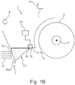
- These side parts 15B and 15C have the function of laterally deflecting the flow of air 10 striking the deflector wall 15 as indicated by arrows 16B and 16C while the central part 15A directs the air flow towards the ground (see arrows 16A of the figure 1B ).
- the free ends of the side parts 15B and 15C are articulated around a pivot axis 18, so that the deflector wall 15 is movably mounted on the support 11 between on the one hand a retracted position ( figure 1A ) in which, in the mounted state, said deflector wall 15 is raised, and on the other hand a deployed position ( figure 1B ) in which, in the assembled state, said deflector wall 15 is lowered and placed upstream of the wheel 3 of the vehicle.
- the pivot axis 18 is in the mounted state of the aerodynamic deflector device substantially parallel to the transverse axis "T" of the vehicle.
- the deflector wall 15 In the retracted position, the deflector wall 15 is raised in a housing located upstream of the wheel arch 5 and therefore does not form any obstacle to the air flow 10 impacting the wheel 5.
- This retracted position is generally adopted for low speeds, for example less than 50 km / h.
- the effect of the deflector wall 15 is not very important, in particular with respect to the reference surface.
- the deflector wall 15 is placed upstream of the wheel 3 of the vehicle while being at least partially below the axis of rotation 17 of said wheel 3.
- the air flow 16B is advantageous because it can contribute to the cooling of the engine compartment.
- the deflector wall 15 itself is more aerodynamic. On the one hand, this is advantageous because it reduces the force necessary for its movement between the retracted and deployed positions.
- the drag force as a whole can be contained to more acceptable values.
- this also makes it possible to provide a thinner deflector wall 15 because the forces exerted on this deflector wall 15 are weaker.
- a closing wall 27 is also provided connecting the lower edges of the central parts 15A and side parts 15B and 15C.
- the aerodynamic deflector device comprises an actuator 19 which is coupled directly to the pivot axis 18 to rotate (see arrow 20 of the figure 1A ) the deflector wall 15 from its retracted position to the deployed position.
- this actuator 19 can have a smaller size, power and consumption because the displacement forces of the wall 15 are low.
- the actuator 19 is for example an electric motor with a rotary output member engaged directly or indirectly with the axis of rotation 17.
- the actuator 19 is for example connected to a control unit 24 comprising for example an electronic circuit such as a microprocessor or a microcontroller receiving speed information from a speed sensor, and ordering the deployment or retraction of the deflector wall. 15 accordingly.
- a control unit 24 comprising for example an electronic circuit such as a microprocessor or a microcontroller receiving speed information from a speed sensor, and ordering the deployment or retraction of the deflector wall. 15 accordingly.
- a hysteresis mechanism is provided in order to avoid threshold effects.
- the control unit 24 triggers the deployment of the deflector wall 15 as soon as the speed exceeds a given threshold (for example 50 km / h), but that the retraction of the deflector is triggered only when the speed drops below a threshold lower than the aforementioned threshold (for example a threshold of 40 km / h).
- the circuit avoids inadvertently triggering alternations of deployment and retraction when the vehicle is traveling at a speed close to the initial threshold and constantly passing from one side to the other of this threshold.
- the deployment triggering threshold (for example 50 km / h) is chosen so as to be high enough for the deployment to have a perceptible effect on the aerodynamic drag.
- the drag varies with the square of the speed. For low speeds, the drag itself is very low. Deploying the deflector is then not useful.
- the threshold for triggering the retraction (for example 40 km / h) is chosen so as to be high enough so that the driver can reasonably envisage crossing obstacles (sidewalks, speed bumps, etc.) at the speed considered. . This prevents the motor vehicle from having to cross such an obstacle (liable to damage the deflector) while the deflector is deployed.
- control unit 24 also receives geolocation data associated with information on the driving situation.
- control unit 24 can be configured to inhibit any deployment of the deflector wall 15 in built-up areas where the speed is limited. In fact, it is in built-up areas that there is the most risk of having to cross obstacles that could damage the deflector wall 15.
- the aerodynamic deflector device 7 makes it possible to improve the aerodynamic drag of the vehicle and therefore in particular the fuel consumption of the vehicle while allowing, by its controlled or active character, the crossing of obstacles at low speed in completely safe.
- the figures 2A to 2D show an aerodynamic deflector device according to a second embodiment.
- the figures 2A and 2B show side perspective diagrams of the aerodynamic deflector device respectively in the retracted position and in the deployed position.
- This embodiment differs from that of figures 1A to 1C by a different shape of the side parts 15B and 15C of the deflector wall 15.
- This rounded shape makes it possible to better guide the air flow 10 in a direction which is substantially parallel to the transverse axis “T” of the vehicle, in particular for the deflected air flow 16B. It is thus possible to deflect the air flow 10 by approximately 90 ° towards the engine compartment of the vehicle.
- the side part 15B of the deflector wall 15 intended to be on the side of the engine compartment has a greater lateral extension than the extension of the other side part 15C of the deflector wall 15.
- the pivot axis 18 comprises a rod, or a set of rods which define the pivot axis, with the actuator 19 being coupled directly to the pivot axis 18, and to the rod, for rotating the deflector wall 15 from its retracted position ( fig. 2A ) to the deployed position ( fig. 2B ).
- the figures 3A to 3C show a third embodiment of the aerodynamic deflector device 7.
- This embodiment differs from that of figures 2A to 2D by the drive mechanism of the deflector wall 15.
- the deflector wall 15 is connected to the plate-shaped support 11 by means of pivot bearings 31 which define the pivot axis 18 of the deflector wall 15.
- the actuator 19 is positioned near the deflector wall 15 and comprises an output lever 33 oriented towards the rear and having at its free end 35 a pin 37 cooperating with a displacement rail 39 of the deflector wall 15.
- the actuator 19 is therefore indirectly coupled to the pivot axis 18.
- the displacement rail 39 is carried by the closing wall 27 and has an oblong hole 41 into which the pin 37 carried by the output lever 33 penetrates.
- the oblong hole 41 extends parallel to the closure wall 27.
- the output lever 33 is oriented perpendicular to the closure wall 27.
- this allows the deployed position to be locked and the actuator 19 to be unloaded, so that no force must be exerted by the actuator 19 to maintain the deflector wall 15 in the deployed position.
- the aerodynamic deflector device is distinguished by its simplicity, its efficiency and its ease of use.
Landscapes
- Engineering & Computer Science (AREA)
- Chemical & Material Sciences (AREA)
- Combustion & Propulsion (AREA)
- Transportation (AREA)
- Mechanical Engineering (AREA)
- Body Structure For Vehicles (AREA)
Claims (12)
- Aerodynamische Ablenkvorrichtung (7) für ein Kraftfahrzeugrad, umfassend:- eine Stütze (11), die zur Montage an einem Kraftfahrzeug konfiguriert ist,- eine Ablenkwand (15), die einerseits beweglich auf dem Träger (11) zwischen einer eingefahrenen Position montiert ist, in der die Ablenkwand (15) im zusammengebauten Zustand relativ zum Träger (11) angehoben ist, und andererseits eine ausgefahrene Position, in der im zusammengebauten Zustand die Umlenkwand (15) relativ zum Träger (11) abgesenkt ist und vor dem Rad (3) des Fahrzeugs platziert werden kann;- einen Aktuator (19), der konfiguriert ist, um die Umlenkwand (15) zwischen der eingefahrenen und der ausgefahrenen Position zu bewegen,dadurch gekennzeichnet, dass die Ablenkwand (15) im Querschnitt einen Mittelteil (15A) und zwei Seitenteile (15B, 15C) aufweist, die vom Mittelteil (15A) abfackeln, um eine divergierende Form in Richtung des Luftstroms zu erhalten (10) Schlagen der Wand (15).
- Vorrichtung nach Anspruch 1, dadurch gekennzeichnet, dass im Querschnitt die Seitenteile (15B, 15C) der Umlenkwand (15) gekrümmt sind.
- Vorrichtung nach Anspruch 2, dadurch gekennzeichnet, dass die Seitenteile (15B, 15C) der Umlenkwand (15) konkav gekrümmt sind.
- Vorrichtung nach Anspruch 3, dadurch gekennzeichnet, dass der seitliche Teil (15B) der Ablenkwand (15), der auf der Seite des Motorraums liegen soll, eine größere seitliche Ausdehnung aufweist als der andere seitliche Teil (15C) der Ablenkung Wand (15).
- Vorrichtung nach einem der Ansprüche 1 bis 4, dadurch gekennzeichnet, dass der Mittelteil (15A) der Umlenkwand (15) im Längsschnitt die Form eines Kreisbogens hat.
- Vorrichtung nach einem der Ansprüche 1 bis 5, dadurch gekennzeichnet, dass die Umlenkwand (15) mittels einer Schwenkachse (18) mit dem Träger (11) verbunden ist und dass der Aktuator (19) direkt ist gekoppelt mit dieser Schwenkachse (18).
- Vorrichtung nach einem der Ansprüche 1 bis 5, dadurch gekennzeichnet, dass die Umlenkwand mittels Schwenklagern (31) mit dem Träger (11) verbunden ist und der Aktuator (19) einen Auslasshebel (33) aufweist an seinem freien Ende (35) ein Stift (37), der mit einer Verschiebungsschiene (39) der Ablenkwand (15) zusammenwirkt.
- Vorrichtung nach Anspruch 7, dadurch gekennzeichnet, dass die Verdrängungsschiene (39) ein Langloch (41) aufweist, in das der vom Auslasshebel (33) getragene Stift (37) eindringt.
- Vorrichtung nach einem der Ansprüche 1 bis 8, dadurch gekennzeichnet, dass sie ferner eine Verschlusswand (27) umfasst, die die beiden Seitenwände (15B, 15C) verbindet und dem Mittelteil (15A) gegenüberliegt.
- Vorrichtung nach Anspruch 7 oder 8 zusammen mit Anspruch 9, dadurch gekennzeichnet, dass die Verdrängungsschiene (39) von der Verschlusswand (27) getragen wird.
- Vorrichtung nach Anspruch 10, dadurch gekennzeichnet, dass sich das Langloch (41) parallel zur Verschlusswand (27) erstreckt und in der ausgefahrenen Position der Auslasshebel (33) senkrecht zur Verschlusswand (27) ausgerichtet ist..
- Kraftfahrzeug, dadurch gekennzeichnet, dass es mindestens eine aerodynamische Ablenkvorrichtung (7) nach einem der Ansprüche 1 bis 11 umfasst, die vor einem Fahrzeugrad (3) angeordnet sind.
Applications Claiming Priority (2)
| Application Number | Priority Date | Filing Date | Title |
|---|---|---|---|
| FR1562574A FR3045550B1 (fr) | 2015-12-17 | 2015-12-17 | Dispositif deflecteur aerodynamique pour roue de vehicule automobile |
| PCT/FR2016/052892 WO2017103357A1 (fr) | 2015-12-17 | 2016-11-08 | Dispositif déflecteur aérodynamique pour roue de véhicule automobile |
Publications (3)
| Publication Number | Publication Date |
|---|---|
| EP3390209A1 EP3390209A1 (de) | 2018-10-24 |
| EP3390209B1 true EP3390209B1 (de) | 2020-07-22 |
| EP3390209B2 EP3390209B2 (de) | 2024-01-31 |
Family
ID=55346069
Family Applications (1)
| Application Number | Title | Priority Date | Filing Date |
|---|---|---|---|
| EP16806264.4A Active EP3390209B2 (de) | 2015-12-17 | 2016-11-08 | Aerodynamische ablenkvorrichtung für kraftfahrzeugrad |
Country Status (5)
| Country | Link |
|---|---|
| US (1) | US10919582B2 (de) |
| EP (1) | EP3390209B2 (de) |
| CN (1) | CN108463398B (de) |
| FR (1) | FR3045550B1 (de) |
| WO (1) | WO2017103357A1 (de) |
Families Citing this family (14)
| Publication number | Priority date | Publication date | Assignee | Title |
|---|---|---|---|---|
| FR3059978B1 (fr) * | 2016-12-13 | 2019-04-19 | Valeo Systemes Thermiques | Dispositif deflecteur aerodynamique pour roue de vehicule automobile |
| FR3071471A1 (fr) * | 2017-09-27 | 2019-03-29 | Compagnie Plastic Omnium | Dispositif deflecteur de vehicule automobile |
| CN111278718B (zh) * | 2017-10-13 | 2022-08-02 | 沃尔沃卡车集团 | 用于机动车辆的轮舱封闭系统和包括这种系统的机动车辆 |
| DE102017128791B4 (de) | 2017-12-05 | 2022-04-28 | Dr. Ing. H.C. F. Porsche Aktiengesellschaft | Frontdiffusor für ein Fahrzeug |
| KR102540890B1 (ko) * | 2018-10-29 | 2023-06-08 | 현대자동차주식회사 | 회전가림 방식 휠 가드 시스템 및 차량 |
| FR3089483A1 (fr) * | 2018-12-07 | 2020-06-12 | Valeo Systemes Thermiques | Dispositif déflecteur pour roue de véhicule automobile |
| DE102019201323B4 (de) | 2019-02-01 | 2022-07-21 | Audi Ag | Luftleitanordnung für ein Fahrzeug |
| KR102692488B1 (ko) * | 2019-05-08 | 2024-08-07 | 현대자동차주식회사 | 차량의 엔진룸 언더커버 |
| DE102019210771B4 (de) * | 2019-07-19 | 2022-04-28 | Magna Exteriors Gmbh | Aktive Radluftabweiseranordnung |
| DE102019006675B4 (de) * | 2019-09-23 | 2022-05-19 | Mercedes-Benz Group AG | Luftleiteinrichtung im Unterbodenbereich eines Kraftwagens |
| US11180203B2 (en) * | 2019-11-19 | 2021-11-23 | Ford Global Technologies, Llc | Active fascia splitter and engine shield |
| CN113443026B (zh) * | 2020-03-24 | 2022-10-11 | 广州汽车集团股份有限公司 | 一种汽车主动式气坝结构及汽车 |
| DE102020209130B4 (de) * | 2020-07-21 | 2023-05-11 | Magna Exteriors Gmbh | Verkleidungsanordnung zur Verkleidung eines Karosserieelements für ein Kraftfahrzeug, sowie ein Verfahren zur zwangsgesteuerten Verlagerung einer Luftleitvorrichtung einer Verkleidungsanordnung |
| CN119975568B (zh) * | 2025-03-21 | 2025-12-09 | 广州汽车集团股份有限公司 | 车身结构、总成、装置及车辆 |
Citations (5)
| Publication number | Priority date | Publication date | Assignee | Title |
|---|---|---|---|---|
| DE2333853A1 (de) | 1973-07-03 | 1975-01-23 | Hasse Friedrich W Dipl Ing | Anti-aquaplaning-vorrichtung |
| JPS63111378U (de) | 1987-01-13 | 1988-07-18 | ||
| FR2858793A1 (fr) | 2003-08-13 | 2005-02-18 | Peugeot Citroen Automobiles Sa | Element aerodynamique pour la reduction de la trainee et de la portance d'un vehicule automobile |
| JP2008013013A (ja) | 2006-07-05 | 2008-01-24 | Mazda Motor Corp | 自動車のタイヤデフレクタ |
| DE102011053350A1 (de) | 2010-09-10 | 2012-03-15 | Fuji Jukogyo Kabushiki Kaisha | Luftströmungs-Ablenkeinrichtung für Fahrzeuge |
Family Cites Families (7)
| Publication number | Priority date | Publication date | Assignee | Title |
|---|---|---|---|---|
| FR793E (fr) * | 1902-02-10 | 1903-03-30 | Duceau Benoit | Un couteau-compteur |
| JPH073264B2 (ja) * | 1986-10-29 | 1995-01-18 | 東京瓦斯株式会社 | ガスコツク |
| JP4301124B2 (ja) * | 2004-09-02 | 2009-07-22 | トヨタ自動車株式会社 | 車両用整流装置 |
| FR2897038B1 (fr) † | 2006-02-06 | 2008-03-21 | Renault Sas | Dispositif aerodynamique pour vehicule |
| JP2008279819A (ja) * | 2007-05-08 | 2008-11-20 | Mazda Motor Corp | 車両前部の下面部構造 |
| DE102011089074A1 (de) * | 2011-12-19 | 2013-06-20 | Bayerische Motoren Werke Aktiengesellschaft | Anordnung einer Luftleitvorrichtung an einem Bauelement eines Fahrzeugs |
| FR3071471A1 (fr) * | 2017-09-27 | 2019-03-29 | Compagnie Plastic Omnium | Dispositif deflecteur de vehicule automobile |
-
2015
- 2015-12-17 FR FR1562574A patent/FR3045550B1/fr not_active Expired - Fee Related
-
2016
- 2016-11-08 EP EP16806264.4A patent/EP3390209B2/de active Active
- 2016-11-08 US US16/060,581 patent/US10919582B2/en not_active Expired - Fee Related
- 2016-11-08 CN CN201680078459.0A patent/CN108463398B/zh not_active Expired - Fee Related
- 2016-11-08 WO PCT/FR2016/052892 patent/WO2017103357A1/fr not_active Ceased
Patent Citations (5)
| Publication number | Priority date | Publication date | Assignee | Title |
|---|---|---|---|---|
| DE2333853A1 (de) | 1973-07-03 | 1975-01-23 | Hasse Friedrich W Dipl Ing | Anti-aquaplaning-vorrichtung |
| JPS63111378U (de) | 1987-01-13 | 1988-07-18 | ||
| FR2858793A1 (fr) | 2003-08-13 | 2005-02-18 | Peugeot Citroen Automobiles Sa | Element aerodynamique pour la reduction de la trainee et de la portance d'un vehicule automobile |
| JP2008013013A (ja) | 2006-07-05 | 2008-01-24 | Mazda Motor Corp | 自動車のタイヤデフレクタ |
| DE102011053350A1 (de) | 2010-09-10 | 2012-03-15 | Fuji Jukogyo Kabushiki Kaisha | Luftströmungs-Ablenkeinrichtung für Fahrzeuge |
Also Published As
| Publication number | Publication date |
|---|---|
| FR3045550A1 (fr) | 2017-06-23 |
| CN108463398A (zh) | 2018-08-28 |
| US10919582B2 (en) | 2021-02-16 |
| EP3390209B2 (de) | 2024-01-31 |
| WO2017103357A1 (fr) | 2017-06-22 |
| US20190233025A1 (en) | 2019-08-01 |
| FR3045550B1 (fr) | 2019-05-17 |
| CN108463398B (zh) | 2021-05-11 |
| EP3390209A1 (de) | 2018-10-24 |
Similar Documents
| Publication | Publication Date | Title |
|---|---|---|
| EP3390209B1 (de) | Aerodynamische ablenkvorrichtung für kraftfahrzeugrad | |
| EP3416874B1 (de) | Aerodynamischer deflektor für ein kraftfahrzeugrad | |
| WO2017098106A1 (fr) | Dispositif déflecteur aérodynamique pour roue de véhicule automobile | |
| EP2485935B1 (de) | Stossdämpfende vorrichtung für ein unter dem fahrzeugrahmen montiertes kraftfahrzeugelement | |
| FR3059964A1 (fr) | Becquet pour vehicule automobile comprenant des ecopes mobiles | |
| EP3426544B1 (de) | Raddeflektor und entsprechendes frontendmodul | |
| WO2017085375A1 (fr) | Deflecteur actif | |
| FR3081820A1 (fr) | Diffuseur arriere mobile de vehicule a panneau escamotable | |
| WO2017013047A1 (fr) | Dispositif d'obturation d'une entree d air, en particulier positionnee sur la face avant d'un vehicule tel qu'un vehicule automobile | |
| FR3048646B1 (fr) | Dispositif d'obturation pour face avant muni de volets mobiles en translation | |
| EP3060455B1 (de) | Kraftfahrzeugvorderstruktur mit einem unter dem stossfänger angeordneten beweglichen spoiler | |
| FR3089942A1 (fr) | Dispositif déflecteur pour roue de véhicule automobile | |
| FR3066445A1 (fr) | Dispositif de regulation d'un flux d'air d'une entree d'air, pour la face avant d'un vehicule | |
| EP3838724A1 (de) | Kraftfahrzeug, einschliesslich eines aerodynamischen deflektorgeräts | |
| FR3089483A1 (fr) | Dispositif déflecteur pour roue de véhicule automobile | |
| FR3073809A1 (fr) | Diffuseur arriere mobile de vehicule a panneau translatant | |
| FR3040662A1 (fr) | Dispositif d'obturation d'entree d'air de face avant de vehicule automobile et module de face avant pour vehicule automobile | |
| FR3081426A1 (fr) | Dispositif deflecteur aerodynamique situe a l'avant d'un vehicule automobile | |
| FR3083198A1 (fr) | Dispositif deflecteur pour roue de vehicule automobile | |
| FR3067319B1 (fr) | Mecanisme de deployement d''un ensemble de generateurs de vortex | |
| WO2019106101A1 (fr) | Dispositif deflecteur a paroi comprenant un moyen d'amenee d'air en aval de la paroi | |
| FR2933040A1 (fr) | Agencement de choc pour un vehicule automobile comportant un module de refroidissement mobile | |
| WO2020002784A1 (fr) | Dispositif deflecteur pour roue de vehicule automobile | |
| EP3880543A1 (de) | Ablenkvorrichtung für ein kraftfahrzeugrad und fahrzeug mit einer solchen vorrichtung |
Legal Events
| Date | Code | Title | Description |
|---|---|---|---|
| STAA | Information on the status of an ep patent application or granted ep patent |
Free format text: STATUS: UNKNOWN |
|
| STAA | Information on the status of an ep patent application or granted ep patent |
Free format text: STATUS: THE INTERNATIONAL PUBLICATION HAS BEEN MADE |
|
| PUAI | Public reference made under article 153(3) epc to a published international application that has entered the european phase |
Free format text: ORIGINAL CODE: 0009012 |
|
| STAA | Information on the status of an ep patent application or granted ep patent |
Free format text: STATUS: REQUEST FOR EXAMINATION WAS MADE |
|
| 17P | Request for examination filed |
Effective date: 20180712 |
|
| AK | Designated contracting states |
Kind code of ref document: A1 Designated state(s): AL AT BE BG CH CY CZ DE DK EE ES FI FR GB GR HR HU IE IS IT LI LT LU LV MC MK MT NL NO PL PT RO RS SE SI SK SM TR |
|
| AX | Request for extension of the european patent |
Extension state: BA ME |
|
| DAV | Request for validation of the european patent (deleted) | ||
| DAX | Request for extension of the european patent (deleted) | ||
| GRAP | Despatch of communication of intention to grant a patent |
Free format text: ORIGINAL CODE: EPIDOSNIGR1 |
|
| STAA | Information on the status of an ep patent application or granted ep patent |
Free format text: STATUS: GRANT OF PATENT IS INTENDED |
|
| INTG | Intention to grant announced |
Effective date: 20200108 |
|
| GRAS | Grant fee paid |
Free format text: ORIGINAL CODE: EPIDOSNIGR3 |
|
| GRAA | (expected) grant |
Free format text: ORIGINAL CODE: 0009210 |
|
| STAA | Information on the status of an ep patent application or granted ep patent |
Free format text: STATUS: THE PATENT HAS BEEN GRANTED |
|
| AK | Designated contracting states |
Kind code of ref document: B1 Designated state(s): AL AT BE BG CH CY CZ DE DK EE ES FI FR GB GR HR HU IE IS IT LI LT LU LV MC MK MT NL NO PL PT RO RS SE SI SK SM TR |
|
| REG | Reference to a national code |
Ref country code: GB Ref legal event code: FG4D Free format text: NOT ENGLISH |
|
| REG | Reference to a national code |
Ref country code: CH Ref legal event code: EP |
|
| REG | Reference to a national code |
Ref country code: DE Ref legal event code: R096 Ref document number: 602016040518 Country of ref document: DE |
|
| REG | Reference to a national code |
Ref country code: AT Ref legal event code: REF Ref document number: 1293123 Country of ref document: AT Kind code of ref document: T Effective date: 20200815 |
|
| REG | Reference to a national code |
Ref country code: IE Ref legal event code: FG4D Free format text: LANGUAGE OF EP DOCUMENT: FRENCH |
|
| REG | Reference to a national code |
Ref country code: LT Ref legal event code: MG4D |
|
| REG | Reference to a national code |
Ref country code: AT Ref legal event code: MK05 Ref document number: 1293123 Country of ref document: AT Kind code of ref document: T Effective date: 20200722 |
|
| PG25 | Lapsed in a contracting state [announced via postgrant information from national office to epo] |
Ref country code: FI Free format text: LAPSE BECAUSE OF FAILURE TO SUBMIT A TRANSLATION OF THE DESCRIPTION OR TO PAY THE FEE WITHIN THE PRESCRIBED TIME-LIMIT Effective date: 20200722 Ref country code: HR Free format text: LAPSE BECAUSE OF FAILURE TO SUBMIT A TRANSLATION OF THE DESCRIPTION OR TO PAY THE FEE WITHIN THE PRESCRIBED TIME-LIMIT Effective date: 20200722 Ref country code: AT Free format text: LAPSE BECAUSE OF FAILURE TO SUBMIT A TRANSLATION OF THE DESCRIPTION OR TO PAY THE FEE WITHIN THE PRESCRIBED TIME-LIMIT Effective date: 20200722 Ref country code: SE Free format text: LAPSE BECAUSE OF FAILURE TO SUBMIT A TRANSLATION OF THE DESCRIPTION OR TO PAY THE FEE WITHIN THE PRESCRIBED TIME-LIMIT Effective date: 20200722 Ref country code: BG Free format text: LAPSE BECAUSE OF FAILURE TO SUBMIT A TRANSLATION OF THE DESCRIPTION OR TO PAY THE FEE WITHIN THE PRESCRIBED TIME-LIMIT Effective date: 20201022 Ref country code: PT Free format text: LAPSE BECAUSE OF FAILURE TO SUBMIT A TRANSLATION OF THE DESCRIPTION OR TO PAY THE FEE WITHIN THE PRESCRIBED TIME-LIMIT Effective date: 20201123 Ref country code: GR Free format text: LAPSE BECAUSE OF FAILURE TO SUBMIT A TRANSLATION OF THE DESCRIPTION OR TO PAY THE FEE WITHIN THE PRESCRIBED TIME-LIMIT Effective date: 20201023 Ref country code: NO Free format text: LAPSE BECAUSE OF FAILURE TO SUBMIT A TRANSLATION OF THE DESCRIPTION OR TO PAY THE FEE WITHIN THE PRESCRIBED TIME-LIMIT Effective date: 20201022 Ref country code: LT Free format text: LAPSE BECAUSE OF FAILURE TO SUBMIT A TRANSLATION OF THE DESCRIPTION OR TO PAY THE FEE WITHIN THE PRESCRIBED TIME-LIMIT Effective date: 20200722 Ref country code: ES Free format text: LAPSE BECAUSE OF FAILURE TO SUBMIT A TRANSLATION OF THE DESCRIPTION OR TO PAY THE FEE WITHIN THE PRESCRIBED TIME-LIMIT Effective date: 20200722 |
|
| REG | Reference to a national code |
Ref country code: DE Ref legal event code: R026 Ref document number: 602016040518 Country of ref document: DE |
|
| PLBI | Opposition filed |
Free format text: ORIGINAL CODE: 0009260 |
|
| PG25 | Lapsed in a contracting state [announced via postgrant information from national office to epo] |
Ref country code: LV Free format text: LAPSE BECAUSE OF FAILURE TO SUBMIT A TRANSLATION OF THE DESCRIPTION OR TO PAY THE FEE WITHIN THE PRESCRIBED TIME-LIMIT Effective date: 20200722 Ref country code: PL Free format text: LAPSE BECAUSE OF FAILURE TO SUBMIT A TRANSLATION OF THE DESCRIPTION OR TO PAY THE FEE WITHIN THE PRESCRIBED TIME-LIMIT Effective date: 20200722 Ref country code: RS Free format text: LAPSE BECAUSE OF FAILURE TO SUBMIT A TRANSLATION OF THE DESCRIPTION OR TO PAY THE FEE WITHIN THE PRESCRIBED TIME-LIMIT Effective date: 20200722 Ref country code: IS Free format text: LAPSE BECAUSE OF FAILURE TO SUBMIT A TRANSLATION OF THE DESCRIPTION OR TO PAY THE FEE WITHIN THE PRESCRIBED TIME-LIMIT Effective date: 20201122 |
|
| 26 | Opposition filed |
Opponent name: MAGNA EXTERIORS GMBH Effective date: 20210208 |
|
| PG25 | Lapsed in a contracting state [announced via postgrant information from national office to epo] |
Ref country code: NL Free format text: LAPSE BECAUSE OF FAILURE TO SUBMIT A TRANSLATION OF THE DESCRIPTION OR TO PAY THE FEE WITHIN THE PRESCRIBED TIME-LIMIT Effective date: 20200722 |
|
| PG25 | Lapsed in a contracting state [announced via postgrant information from national office to epo] |
Ref country code: SM Free format text: LAPSE BECAUSE OF FAILURE TO SUBMIT A TRANSLATION OF THE DESCRIPTION OR TO PAY THE FEE WITHIN THE PRESCRIBED TIME-LIMIT Effective date: 20200722 Ref country code: EE Free format text: LAPSE BECAUSE OF FAILURE TO SUBMIT A TRANSLATION OF THE DESCRIPTION OR TO PAY THE FEE WITHIN THE PRESCRIBED TIME-LIMIT Effective date: 20200722 Ref country code: IT Free format text: LAPSE BECAUSE OF FAILURE TO SUBMIT A TRANSLATION OF THE DESCRIPTION OR TO PAY THE FEE WITHIN THE PRESCRIBED TIME-LIMIT Effective date: 20200722 Ref country code: CZ Free format text: LAPSE BECAUSE OF FAILURE TO SUBMIT A TRANSLATION OF THE DESCRIPTION OR TO PAY THE FEE WITHIN THE PRESCRIBED TIME-LIMIT Effective date: 20200722 Ref country code: DK Free format text: LAPSE BECAUSE OF FAILURE TO SUBMIT A TRANSLATION OF THE DESCRIPTION OR TO PAY THE FEE WITHIN THE PRESCRIBED TIME-LIMIT Effective date: 20200722 Ref country code: RO Free format text: LAPSE BECAUSE OF FAILURE TO SUBMIT A TRANSLATION OF THE DESCRIPTION OR TO PAY THE FEE WITHIN THE PRESCRIBED TIME-LIMIT Effective date: 20200722 |
|
| PLAX | Notice of opposition and request to file observation + time limit sent |
Free format text: ORIGINAL CODE: EPIDOSNOBS2 |
|
| PG25 | Lapsed in a contracting state [announced via postgrant information from national office to epo] |
Ref country code: AL Free format text: LAPSE BECAUSE OF FAILURE TO SUBMIT A TRANSLATION OF THE DESCRIPTION OR TO PAY THE FEE WITHIN THE PRESCRIBED TIME-LIMIT Effective date: 20200722 |
|
| PG25 | Lapsed in a contracting state [announced via postgrant information from national office to epo] |
Ref country code: MC Free format text: LAPSE BECAUSE OF FAILURE TO SUBMIT A TRANSLATION OF THE DESCRIPTION OR TO PAY THE FEE WITHIN THE PRESCRIBED TIME-LIMIT Effective date: 20200722 Ref country code: SK Free format text: LAPSE BECAUSE OF FAILURE TO SUBMIT A TRANSLATION OF THE DESCRIPTION OR TO PAY THE FEE WITHIN THE PRESCRIBED TIME-LIMIT Effective date: 20200722 |
|
| REG | Reference to a national code |
Ref country code: CH Ref legal event code: PL |
|
| GBPC | Gb: european patent ceased through non-payment of renewal fee |
Effective date: 20201108 |
|
| PG25 | Lapsed in a contracting state [announced via postgrant information from national office to epo] |
Ref country code: LU Free format text: LAPSE BECAUSE OF NON-PAYMENT OF DUE FEES Effective date: 20201108 |
|
| PLBB | Reply of patent proprietor to notice(s) of opposition received |
Free format text: ORIGINAL CODE: EPIDOSNOBS3 |
|
| REG | Reference to a national code |
Ref country code: BE Ref legal event code: MM Effective date: 20201130 |
|
| PG25 | Lapsed in a contracting state [announced via postgrant information from national office to epo] |
Ref country code: SI Free format text: LAPSE BECAUSE OF FAILURE TO SUBMIT A TRANSLATION OF THE DESCRIPTION OR TO PAY THE FEE WITHIN THE PRESCRIBED TIME-LIMIT Effective date: 20200722 Ref country code: LI Free format text: LAPSE BECAUSE OF NON-PAYMENT OF DUE FEES Effective date: 20201130 Ref country code: CH Free format text: LAPSE BECAUSE OF NON-PAYMENT OF DUE FEES Effective date: 20201130 |
|
| REG | Reference to a national code |
Ref country code: NL Ref legal event code: MP Effective date: 20200722 |
|
| PG25 | Lapsed in a contracting state [announced via postgrant information from national office to epo] |
Ref country code: IE Free format text: LAPSE BECAUSE OF NON-PAYMENT OF DUE FEES Effective date: 20201108 |
|
| PG25 | Lapsed in a contracting state [announced via postgrant information from national office to epo] |
Ref country code: GB Free format text: LAPSE BECAUSE OF NON-PAYMENT OF DUE FEES Effective date: 20201108 |
|
| PG25 | Lapsed in a contracting state [announced via postgrant information from national office to epo] |
Ref country code: IS Free format text: LAPSE BECAUSE OF FAILURE TO SUBMIT A TRANSLATION OF THE DESCRIPTION OR TO PAY THE FEE WITHIN THE PRESCRIBED TIME-LIMIT Effective date: 20201122 Ref country code: TR Free format text: LAPSE BECAUSE OF FAILURE TO SUBMIT A TRANSLATION OF THE DESCRIPTION OR TO PAY THE FEE WITHIN THE PRESCRIBED TIME-LIMIT Effective date: 20200722 Ref country code: MT Free format text: LAPSE BECAUSE OF FAILURE TO SUBMIT A TRANSLATION OF THE DESCRIPTION OR TO PAY THE FEE WITHIN THE PRESCRIBED TIME-LIMIT Effective date: 20200722 Ref country code: CY Free format text: LAPSE BECAUSE OF FAILURE TO SUBMIT A TRANSLATION OF THE DESCRIPTION OR TO PAY THE FEE WITHIN THE PRESCRIBED TIME-LIMIT Effective date: 20200722 |
|
| PG25 | Lapsed in a contracting state [announced via postgrant information from national office to epo] |
Ref country code: MK Free format text: LAPSE BECAUSE OF FAILURE TO SUBMIT A TRANSLATION OF THE DESCRIPTION OR TO PAY THE FEE WITHIN THE PRESCRIBED TIME-LIMIT Effective date: 20200722 |
|
| PG25 | Lapsed in a contracting state [announced via postgrant information from national office to epo] |
Ref country code: BE Free format text: LAPSE BECAUSE OF NON-PAYMENT OF DUE FEES Effective date: 20201130 |
|
| P01 | Opt-out of the competence of the unified patent court (upc) registered |
Effective date: 20230528 |
|
| APAH | Appeal reference modified |
Free format text: ORIGINAL CODE: EPIDOSCREFNO |
|
| APBM | Appeal reference recorded |
Free format text: ORIGINAL CODE: EPIDOSNREFNO |
|
| APBP | Date of receipt of notice of appeal recorded |
Free format text: ORIGINAL CODE: EPIDOSNNOA2O |
|
| APBU | Appeal procedure closed |
Free format text: ORIGINAL CODE: EPIDOSNNOA9O |
|
| PUAH | Patent maintained in amended form |
Free format text: ORIGINAL CODE: 0009272 |
|
| STAA | Information on the status of an ep patent application or granted ep patent |
Free format text: STATUS: PATENT MAINTAINED AS AMENDED |
|
| 27A | Patent maintained in amended form |
Effective date: 20240131 |
|
| AK | Designated contracting states |
Kind code of ref document: B2 Designated state(s): AL AT BE BG CH CY CZ DE DK EE ES FI FR GB GR HR HU IE IS IT LI LT LU LV MC MK MT NL NO PL PT RO RS SE SI SK SM TR |
|
| PGFP | Annual fee paid to national office [announced via postgrant information from national office to epo] |
Ref country code: FR Payment date: 20231124 Year of fee payment: 8 Ref country code: DE Payment date: 20231107 Year of fee payment: 8 |
|
| REG | Reference to a national code |
Ref country code: DE Ref legal event code: R102 Ref document number: 602016040518 Country of ref document: DE |
|
| REG | Reference to a national code |
Ref country code: DE Ref legal event code: R119 Ref document number: 602016040518 Country of ref document: DE |
|
| PG25 | Lapsed in a contracting state [announced via postgrant information from national office to epo] |
Ref country code: DE Free format text: LAPSE BECAUSE OF NON-PAYMENT OF DUE FEES Effective date: 20250603 |
|
| PG25 | Lapsed in a contracting state [announced via postgrant information from national office to epo] |
Ref country code: FR Free format text: LAPSE BECAUSE OF NON-PAYMENT OF DUE FEES Effective date: 20241130 |