EP3390266B1 - Hubarbeitsbühne - Google Patents
Hubarbeitsbühne Download PDFInfo
- Publication number
- EP3390266B1 EP3390266B1 EP16815829.3A EP16815829A EP3390266B1 EP 3390266 B1 EP3390266 B1 EP 3390266B1 EP 16815829 A EP16815829 A EP 16815829A EP 3390266 B1 EP3390266 B1 EP 3390266B1
- Authority
- EP
- European Patent Office
- Prior art keywords
- platform
- control console
- lighting device
- aerial lift
- lift according
- Prior art date
- Legal status (The legal status is an assumption and is not a legal conclusion. Google has not performed a legal analysis and makes no representation as to the accuracy of the status listed.)
- Active
Links
Images



Classifications
-
- B—PERFORMING OPERATIONS; TRANSPORTING
- B66—HOISTING; LIFTING; HAULING
- B66F—HOISTING, LIFTING, HAULING OR PUSHING, NOT OTHERWISE PROVIDED FOR, e.g. DEVICES WHICH APPLY A LIFTING OR PUSHING FORCE DIRECTLY TO THE SURFACE OF A LOAD
- B66F11/00—Lifting devices specially adapted for particular uses not otherwise provided for
- B66F11/04—Lifting devices specially adapted for particular uses not otherwise provided for for movable platforms or cabins, e.g. on vehicles, permitting workmen to place themselves in any desired position for carrying out required operations
- B66F11/044—Working platforms suspended from booms
-
- B—PERFORMING OPERATIONS; TRANSPORTING
- B66—HOISTING; LIFTING; HAULING
- B66F—HOISTING, LIFTING, HAULING OR PUSHING, NOT OTHERWISE PROVIDED FOR, e.g. DEVICES WHICH APPLY A LIFTING OR PUSHING FORCE DIRECTLY TO THE SURFACE OF A LOAD
- B66F17/00—Safety devices, e.g. for limiting or indicating lifting force
- B66F17/006—Safety devices, e.g. for limiting or indicating lifting force for working platforms
Definitions
- the invention relates to a lifting platform.
- the lifting nacelles and more generally the mobile lifting platforms for personnel (PEMP), comprise a platform mounted on lifting means making it possible to work at height. During the winter season, work can be carried out in low light conditions, which implies the use of lighting.
- PEMP mobile lifting platforms for personnel
- the invention intends to remedy by proposing a new lifting platform, whose access and working comfort in low light conditions is improved.
- the invention relates to an elevating nacelle including a lower part equipped with ground connection members; a platform comprising a floor partially surrounded by a railing in which an access zone is provided, and an elevating structure carrying the platform.
- This nacelle is characterized in that the platform is equipped with a lighting system, other than driving lights, adapted to light at least partially an interior space of the platform, including at least the access area.
- an elevating nacelle 1 comprising a lower part including a chassis 3 equipped with ground connection members, such as wheels or tracks.
- the lower part also comprises a turret 5 movable in rotation relative to the chassis 3 along an axis perpendicular to the axes of rotation of the wheels, a lifting structure 7 and a platform 9, shown in figures 2 , 3 and 4 , supported by the lifting structure 7.
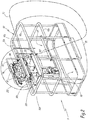
- the platform 9 comprises a mesh floor 90 surrounded by a railing 92.
- the railing 92 comprises an upper tube parallel to the mesh floor 90 and formed by four sections including a rear section 92a, of great length and located on the side opposite to the connection of the lifting structure 7 on the platform 9.
- An access area 93 is preferably arranged on the side of the rear section 92a.
- the upper tube also includes a front section 92b opposite the rear section 92a, and oriented towards the side of the lifting structure 7. Between the sections 92a and 92b, two lateral sections 92c and 92d complete the upper tube.
- the access area 93 can be provided on the side of one of the lateral sections 92c and 92d.
- nacelle 1 In configuration of use of nacelle 1, the operator (s) use a work area located on the side of sections 92a, 92c and 92d. These parts of the railing 92 are exposed to shocks and dirt.
- the access area 93 is formed by a mobile part 92f of a horizontal bar 92e of the railing 92, this mobile part 92f being adapted to be lifted and allow the entry of a person onto the platform 9.
- the access area 93 may be formed by a door articulated with respect to the railing 92.
- the platform 9 is equipped with a control console 94 making it possible to control the lifting platform 1, in particular the movements of the platform 9 relative to the chassis 3, and which mounted in the center of the front section 92b of the railing 92.
- the platform 9 is equipped with a lighting system other than driving lights, adapted to light at least partially an interior space E of the platform 9, that is to say the volume bounded by the railing, including at least part of the access area 93, so that an operator outside the platform 9 can spot it in the dark and access it safely, and to facilitate the work of operators on the platform in low light conditions.
- a lighting system other than driving lights adapted to light at least partially an interior space E of the platform 9, that is to say the volume bounded by the railing, including at least part of the access area 93, so that an operator outside the platform 9 can spot it in the dark and access it safely, and to facilitate the work of operators on the platform in low light conditions.
- the lighting system of the platform 9 for this purpose comprises a first lighting device comprising at least one light source, provided on a railing portion 92 remote from the work area, and directed towards the interior of the platform 9.
- the intensity of illumination provided by the first lighting system is medium or low, that is to say preferably between one and five lux at two meters.
- the first lighting device comprises two light sources 100 and 101 such as for example light-emitting diodes (hereinafter LED) fixed on the control console 94 and which light the interior area E of the platform 9, the access area 93 of the platform 9 by forming light beams F1 and F2.
- the beams F1 and F2 are confused.
- the beams F1 and F2 are directed in a horizontal direction, in the direction of an outer side of the lifting platform 1, that is to say in the direction of section 92a.
- the light sources 100 and 101 are adapted so that the beams F1 and F2 illuminate the entire section 92a.
- the light sources 100 and 101 are provided on the control console 94 makes it possible to avoid their exposure to possible shocks, since they are not located on the sides of the railing 92 corresponding to sections 92a, 92c and 92d, where impacts with an external element are likely to occur.
- the integration of the light sources 100 and 101 on the control console 94 makes it possible to minimize the length of cables necessary for their electrical supply.
- the light sources 100 and 101 are each fixed under a flange 941 of the control desk 94, in order to be protected from impacts coming from above.
- the platform 9 also comprises mechanical structures for protecting light sources 100 and 101, formed for example by metal bars 106 and 107 arranged around the control desk 94 and which can be connected to the railing 92.
- the first lighting device also illuminates the immediate environment of the platform 9 so that an operator present on the platform 9 is able to move the platform 9 relative to the chassis 3 and to the turret 5 in an unlit environment.
- the lighting system is adapted to light the surroundings of the platform 9 at a medium or low intensity so as to identify a possible obstacle sufficiently early.
- the beams F1 and F2 make it possible to illuminate, for example, a vertical wall M located in the immediate environment of the platform 9, so that the operator controlling the movement of the platform 9 relative to the chassis 3 can ensure that the platform 9 does not strike the wall M in the dark.
- the maximum speed of movement of the platform 9 relative to the ground is generally limited to 0.7 meters per second when the lifting structure 7 is unfolded.
- the light beams F1 and F2 are adapted to illuminate the immediate environment of the platform 9 up to a determined distance from the platform 9, for example two meters. This distance and an intensity of illumination between 1 and 5 lux at two meters are sufficient to immobilize the platform 9 before an obstacle.
- the lifting movements of the platform take place at a maximum speed of 0.4 m / s, and the rotation of the turret 5 takes place at a maximum speed of 0.7 km / h.
- Such lighting is distinguished from a work spotlight, which illuminates a precise area with a strong intensity, that is to say at least equal to twenty lux at two meters allowing an operator to perform a precise task, or a driving light, adapted to illuminate the environment located on the ground in front of the chassis of a vehicle when it is moving, and not the immediate environment of the vehicle, which remains in the dark.
- the first lighting device is not used in the displacement configuration relative to the ground with the lifting structure 7 folded, because the speed is greater and requires driving lights.
- the lighting system of the platform 9 also includes a second lighting device adapted to illuminate the control console 94.
- the control console 94 includes indicator lights, switches and one or more manual control members 94a, 94b and 94c allowing the control of the functionalities of the lifting platform 1.
- the control desk 94 must be usable by an operator located in the platform 9 in low light conditions.
- the second lighting device for this purpose comprises at least one light source fixed on the control console 94. In the example shown, the second lighting device comprises two light sources 104 and 105 fixed on the control console 94, on either side of a central island 95.
- the control desk 94 advantageously comprises a folding protective cover 96 making it possible to protect the control members and the other components outside the ranges of use of the lifting platform 1.
- the cover 96 is shown open to figures 1 , 2 and 3 .
- An internal face of the folding cover 96 includes reflecting surfaces 97 located opposite the light sources 104 and 105 so that the reflecting surfaces 97 diffuse the light produced by the light sources 104 and 105 on the control console 94, like this is represented by the luminous fluxes F3 and F4 at the figure 3 , which allows the operator to distinguish the control panel 94 clearly enough to consult the status of the machine and use the switches and manual controls in low light configuration.
- the lighting system also comprises a third lighting device suitable for lighting the immediate environment of the platform 9 located under the platform 9.
- This third lighting device advantageously comprises a light source 103, such as for example an LED , which projects a light beam F5 directed downwards and making it possible to illuminate an obstacle located under the platform 9, for example a roof T of a building in the vicinity of which the lifting platform 14 is used.
- the light source 103 is preferably fixed under the floor 90.
- the three lighting devices described above can be equipped, in place of LEDs, with other types of light sources, and include different numbers of light sources while fulfilling the same functions.
- the lighting system of the platform 9 can incorporate only the first lighting device or else only the second lighting device.
- the lower part is also equipped with a control console 50, provided for example on one side of the turret 5, accessible by a person on the ground, and in particular allowing the starting of the lifting platform 1 , and the control of certain movements of platform 9 in the event of an emergency.
- the control console 50 is provided with a lighting device 52, which may include one or more light sources such as LEDs.
- an operator can decide to transfer control of the nacelle 1 to the control console 94 of the platform 9, which will activate the lighting of the platform 9 so that the operator can to access. Indeed, for the lifting nacelles whose lifting structure 7 is of great length, the operator may have to travel several meters to access the platform 9. In such a case, the lighting of part of the platform 9 allows the operator to easily navigate in the dark towards the platform 9, locate the access area 93 there and access it.
- the invention is not limited to a lifting platform with a turret and articulated arm as shown in this example, and also applies to all types of personnel lifting platforms, in particular lifting structures of the telescopic arm type, chisel and vertical mast and nacelles mounted on a truck chassis or a trailer chassis.
- a person who is on the platform and who has to direct the maneuver of the platform and the lifting platform in height or above the ground is capable of distinguishing possible obstacles in the environment close to the platform.
- the first and second lighting devices can be one and constitute a single lighting device suitable for both illuminating the access area to the platform, l environment and the control console.
Landscapes
- Engineering & Computer Science (AREA)
- Structural Engineering (AREA)
- Mechanical Engineering (AREA)
- Life Sciences & Earth Sciences (AREA)
- Geology (AREA)
- Forklifts And Lifting Vehicles (AREA)
- Non-Portable Lighting Devices Or Systems Thereof (AREA)
Claims (12)
- Hubarbeitsbühne (1) umfassend:- einen unteren Teil (3, 5), der mit Mitteln für die Verbindung mit dem Erdboden ausgestattet ist;- eine Plattform (9), die einen Boden (90) umfasst, der teilweise von einem Schutzgeländer (92) umgeben ist, in dem eine Zutrittszone (93) vorgesehen ist,- eine Hebestruktur (7), welche die Plattform (9) trägt;dadurch gekennzeichnet, dass die Plattform (9) mit einem Beleuchtungssystem (100, 101, 103, 104, 105) ausgestattet ist, das von Fahrscheinwerfern verschieden ist und eingerichtet ist, mindestens teilweise einen Innenraum (E) der Plattform (9) zu beleuchten, der mindestens die Zutrittszone (93) umfasst.
- Hubarbeitsbühne nach Anspruch 1, dadurch gekennzeichnet, dass das Beleuchtungssystem der Plattform (9) eine erste Beleuchtungsvorrichtung (100, 101) umfasst, die mindestens eine Lichtquelle (100, 101) umfasst, die an einem Teil des Schutzgeländers (92) vorgesehen ist, der von Arbeitsbereichen (92a, 92c, 92d) der Plattform (9) entfernt ist, und einen Lichtstrahl (F1, F2) emittiert, der zu dem Inneren der Plattform (9) hin gerichtet ist.
- Hubarbeitsbühne nach Anspruch 2, dadurch gekennzeichnet, dass die Plattform (9) ein Steuerpult (94) umfasst, das an dem von den Arbeitsbereichen (92a, 92c, 92d) entfernten Teil des Schutzgeländers (92) montiert ist, und dass die Lichtquelle (100, 101) der ersten Beleuchtungsvorrichtung an dem Steuerpult (94) befestigt ist.
- Hubarbeitsbühne nach einem der Ansprüche 2 und 3, dadurch gekennzeichnet, dass die erste Beleuchtungsvorrichtung (100, 101) ferner eingerichtet ist, um die unmittelbare Umgebung der Plattform (9) zu beleuchten, so dass ein auf der Plattform (9) anwesender Bediener in der Lage ist, Bewegungen der Plattform (9) relativ zu dem unteren Teil (3, 5) in einer nicht beleuchteten Umgebung durchzuführen.
- Hubarbeitsbühne nach Anspruch 4, dadurch gekennzeichnet, dass die erste Beleuchtungsvorrichtung (100, 101) die unmittelbare Umgebung der Plattform (9) beleuchtet, die sich in gleicher Höhe über dem Erdboden wie die Plattform (9) und in einer horizontalen Richtung befindet, bis zu einem Abstand von der Plattform (9), der mindestens zwei Meter beträgt.
- Hubarbeitsbühne nach einem der vorhergehenden Ansprüche, dadurch gekennzeichnet, dass die Plattform (9) ein Steuerpult (94) umfasst und dass das Beleuchtungssystem der Plattform (9) eine zweite Beleuchtungsvorrichtung (104, 105) umfasst, die eingerichtet ist, um das Steuerpult (94) zu beleuchten.
- Hubarbeitsbühne nach Anspruch 6, dadurch gekennzeichnet, dass das Steuerpult (94) eine klappbare Schutzabdeckung (96) umfasst, deren Innenseite reflektierende Oberflächen (97) umfasst, die eingerichtet sind, um das von der zweiten Beleuchtungsvorrichtung (104, 105) erzeugte Licht auf dem Steuerpult (94) zu verbreiten (F3, F4), wenn die Schutzabdeckung (96) in einer angehobenen Stellung ist, die Zugriff auf das Steuerpult (94) gibt.
- Hubarbeitsbühne nach Anspruch 7, dadurch gekennzeichnet, dass die zweite Beleuchtungsvorrichtung mindestens eine Lichtquelle (104, 105) umfasst, die an dem Steuerpult (94) befestigt ist.
- Hubarbeitsbühne nach einem der vorhergehenden Ansprüche, dadurch gekennzeichnet, dass die Plattform (9) eine dritte Beleuchtungsvorrichtung (103) umfasst, die eingerichtet ist, um die unmittelbare Umgebung der Plattform (9), die sich unter der Plattform (9) befindet, zu beleuchten (F5).
- Hubarbeitsbühne nach Anspruch 9, dadurch gekennzeichnet, dass die dritte Beleuchtungsvorrichtung mindestens eine Lichtquelle (103) umfasst, die unter einem Boden (90) der Plattform (9) befestigt ist.
- Hubarbeitsbühne nach einem der vorhergehenden Ansprüche, dadurch gekennzeichnet, dass die Aktivierung des Beleuchtungssystems der Plattform (9) ausgehend von dem unteren Teil (3, 5) aus der Ferne steuerbar ist.
- Hubarbeitsbühne nach Anspruch 11, dadurch gekennzeichnet, dass der untere Teil (3, 5) mit einem Steuerpult (50) ausgestattet ist, ausgehend von dem die Aktivierung des Beleuchtungssystems der Plattform (9) gesteuert wird, und dass das Steuerpult (50) des unteren Teils (3, 5) mit einer Beleuchtungsvorrichtung(52) dieses Steuerpults (50) ausgestattet ist.
Applications Claiming Priority (2)
| Application Number | Priority Date | Filing Date | Title |
|---|---|---|---|
| FR1562761A FR3045589B1 (fr) | 2015-12-18 | 2015-12-18 | Nacelle elevatrice |
| PCT/EP2016/081415 WO2017103099A1 (fr) | 2015-12-18 | 2016-12-16 | Nacelle élévatrice |
Publications (2)
| Publication Number | Publication Date |
|---|---|
| EP3390266A1 EP3390266A1 (de) | 2018-10-24 |
| EP3390266B1 true EP3390266B1 (de) | 2020-01-01 |
Family
ID=55862900
Family Applications (1)
| Application Number | Title | Priority Date | Filing Date |
|---|---|---|---|
| EP16815829.3A Active EP3390266B1 (de) | 2015-12-18 | 2016-12-16 | Hubarbeitsbühne |
Country Status (7)
| Country | Link |
|---|---|
| US (1) | US20180362313A1 (de) |
| EP (1) | EP3390266B1 (de) |
| CN (1) | CN108367903B (de) |
| AU (1) | AU2016369398A1 (de) |
| CA (1) | CA3006402A1 (de) |
| FR (1) | FR3045589B1 (de) |
| WO (1) | WO2017103099A1 (de) |
Families Citing this family (16)
| Publication number | Priority date | Publication date | Assignee | Title |
|---|---|---|---|---|
| FR3044652B1 (fr) * | 2015-12-08 | 2018-01-05 | Haulotte Group | Poste de commande pour plate-forme de travail de nacelle elevatrice |
| FR3045169B1 (fr) * | 2015-12-09 | 2018-01-12 | Haulotte Group | Pupitre de commande et nacelle elevatrice comprenant un tel pupitre de commande |
| US10815106B2 (en) | 2016-06-10 | 2020-10-27 | Altec Industries, Inc. | Step system for elevating platform |
| US12187588B2 (en) | 2016-06-10 | 2025-01-07 | Altec Industries, Inc. | Modular rib |
| US10822216B2 (en) * | 2016-06-10 | 2020-11-03 | Altec Industries, Inc. | Modular rib for elevating platform |
| US10823327B2 (en) | 2016-06-10 | 2020-11-03 | Altec Industries, Inc. | Mounting system for elevating platform |
| FR3054540B1 (fr) * | 2016-07-28 | 2018-09-07 | Haulotte Group | Poste auxiliaire de commande de nacelle elevatrice |
| FR3056203B1 (fr) * | 2016-09-21 | 2020-10-09 | Haulotte Group | Assistance visuelle au deplacement au sol d'une nacelle elevatrice |
| FR3067341B1 (fr) * | 2017-06-12 | 2019-07-26 | Haulotte Group | Nacelle elevatrice a placement automatique en position compacte de transport |
| WO2021041708A1 (en) * | 2019-08-28 | 2021-03-04 | Oshkosh Corporation | Fall arrest system |
| US12202715B2 (en) * | 2020-01-16 | 2025-01-21 | Xtreme Manufacturing, Llc | Telehandler boom auxiliary control panel |
| US11919756B2 (en) | 2020-02-04 | 2024-03-05 | Xtreme Manufacturing, Llc | Aerial work vehicle boom auxiliary control panel |
| CN112551452B (zh) * | 2020-11-30 | 2022-08-23 | 上海市建筑科学研究院科技发展有限公司 | 一种多功能检测装置 |
| CN114212745B (zh) * | 2022-01-17 | 2024-10-11 | 徐工消防安全装备有限公司 | 一种高空作业平台、控制方法及存储介质 |
| FR3138077B1 (fr) * | 2022-07-22 | 2024-06-21 | Manitou Bf | Engin de manutention de charge et/ou de personne |
| US20250091851A1 (en) * | 2023-09-18 | 2025-03-20 | Altec Industries, Inc. | Material handler for aerial platforms |
Family Cites Families (14)
| Publication number | Priority date | Publication date | Assignee | Title |
|---|---|---|---|---|
| US3605941A (en) * | 1969-01-09 | 1971-09-20 | Gen Cable Corp | Aerial lift with rotatable and enclosable basket |
| US4165799A (en) * | 1978-07-07 | 1979-08-28 | Munoz German R | Dismountable tower for interior maintenance of spherical tanks |
| JPH0749360B2 (ja) * | 1991-10-31 | 1995-05-31 | 株式会社ジャパニック | 高所作業車の安全機構 |
| SG82672A1 (en) * | 1999-02-04 | 2001-08-21 | Snorkel International Inc | Aerial work platform boom having ground and platform controls linked by a controller area network |
| US6145619A (en) * | 1999-05-06 | 2000-11-14 | Aerial Innovations Incorporated | Foldable personnel basket for mobile equipment |
| DE102005056305A1 (de) * | 2005-11-24 | 2007-06-06 | Siemens Ag | Cockpitmodul |
| US10358331B2 (en) * | 2010-12-20 | 2019-07-23 | Jlg Industries, Inc. | Work platform with protection against sustained involuntary operation |
| US9336660B2 (en) * | 2010-03-11 | 2016-05-10 | David McIntosh | Overhead hazard warning systems |
| CN202968037U (zh) * | 2012-12-12 | 2013-06-05 | 吴有中 | 用于电力设备安装和维护的升降装置 |
| FR3002799B1 (fr) * | 2013-03-01 | 2015-07-31 | Haulotte Group | Cellule de mesure d'effort pour nacelle elevatrice et nacelle elevatrice comprenant une telle cellule |
| CN203238002U (zh) * | 2013-04-01 | 2013-10-16 | 王玉彪 | 一种夜用升降机 |
| CN103626087A (zh) * | 2013-10-31 | 2014-03-12 | 苏州富士德物流设备有限公司 | 一种物流用升降台 |
| CN204689585U (zh) * | 2015-04-28 | 2015-10-07 | 浙江大道建设工程有限公司 | 市政抢险升降机 |
| US20160101722A1 (en) * | 2015-12-17 | 2016-04-14 | Caterpillar Paving Products Inc. | Light actuation system for machines |
-
2015
- 2015-12-18 FR FR1562761A patent/FR3045589B1/fr not_active Expired - Fee Related
-
2016
- 2016-12-16 AU AU2016369398A patent/AU2016369398A1/en not_active Abandoned
- 2016-12-16 CN CN201680071761.3A patent/CN108367903B/zh active Active
- 2016-12-16 EP EP16815829.3A patent/EP3390266B1/de active Active
- 2016-12-16 US US16/062,940 patent/US20180362313A1/en not_active Abandoned
- 2016-12-16 CA CA3006402A patent/CA3006402A1/fr active Pending
- 2016-12-16 WO PCT/EP2016/081415 patent/WO2017103099A1/fr not_active Ceased
Non-Patent Citations (1)
| Title |
|---|
| None * |
Also Published As
| Publication number | Publication date |
|---|---|
| EP3390266A1 (de) | 2018-10-24 |
| CN108367903B (zh) | 2020-07-28 |
| WO2017103099A1 (fr) | 2017-06-22 |
| US20180362313A1 (en) | 2018-12-20 |
| CN108367903A (zh) | 2018-08-03 |
| FR3045589B1 (fr) | 2018-02-02 |
| CA3006402A1 (fr) | 2017-06-22 |
| AU2016369398A1 (en) | 2018-06-21 |
| FR3045589A1 (fr) | 2017-06-23 |
Similar Documents
| Publication | Publication Date | Title |
|---|---|---|
| EP3390266A1 (de) | Korb einer luftseilbahn | |
| CA2970555C (fr) | Nacelle elevatrice a dispositif d'eclairage generant de la lumiere dirigee vers le sol, ainsi que procede de mise en oeuvre | |
| EP3233714B1 (de) | Luftaufzug und verfahren zur implementierung davon | |
| EP3442899B1 (de) | Bedienpult mit anti-zerquetsch-schutz des betreibers, für eine hubgondel-arbeitshebebühne | |
| EP3387498B1 (de) | Steuerkonsole und luftseilbahn mit solch einer steuerkonsole | |
| EP3458406B1 (de) | System zur unterstützung der beurteilung und verwaltung einer gefahr bei einem freileitungslift | |
| FR3056203A1 (fr) | Assistance visuelle au deplacement au sol d'une nacelle elevatrice | |
| FR3067341A1 (fr) | Nacelle elevatrice a placement automatique en position compacte de transport | |
| FR3091329A1 (fr) | Système de feu de gabarit | |
| FR3008404A1 (fr) | Plateforme de nacelle elevatrice et nacelle elevatrice equipee d'une telle plateforme | |
| EP2810825B1 (de) | Vorrichtung zum Rückwärtssehen für ein Kraftfahrzeug | |
| EP4619335A1 (de) | Verfahren und system zum schutz eines bedieners eines hubwerks gegen zertrümmerung und hubwerk mit diesem system | |
| EP1340708A1 (de) | Hubarbeitsbühne, und Montageverfahren mittels solcher Arbeitsbühne | |
| FR3160684A1 (fr) | Nacelle élévatrice | |
| EP1520832A1 (de) | Ein Fahrzeug zum Heben eines Persons und seines Arbeitskorbes | |
| EP1577197A3 (de) | Kraftfahrzeug mit einem, mittels eines Hebezeuges, heb-und senkbaren Ersatzrad | |
| FR2675494A1 (fr) | Dispositif de commande d'une nacelle pivotante montee sur un engin de levage. | |
| FR3129385A1 (fr) | Chariot élévateur équipé d’une surveillance d’environnement | |
| FR3081131A3 (fr) | Retroviseur interieur de vehicule avec camera integree |
Legal Events
| Date | Code | Title | Description |
|---|---|---|---|
| STAA | Information on the status of an ep patent application or granted ep patent |
Free format text: STATUS: UNKNOWN |
|
| STAA | Information on the status of an ep patent application or granted ep patent |
Free format text: STATUS: THE INTERNATIONAL PUBLICATION HAS BEEN MADE |
|
| PUAI | Public reference made under article 153(3) epc to a published international application that has entered the european phase |
Free format text: ORIGINAL CODE: 0009012 |
|
| STAA | Information on the status of an ep patent application or granted ep patent |
Free format text: STATUS: REQUEST FOR EXAMINATION WAS MADE |
|
| 17P | Request for examination filed |
Effective date: 20180604 |
|
| AK | Designated contracting states |
Kind code of ref document: A1 Designated state(s): AL AT BE BG CH CY CZ DE DK EE ES FI FR GB GR HR HU IE IS IT LI LT LU LV MC MK MT NL NO PL PT RO RS SE SI SK SM TR |
|
| AX | Request for extension of the european patent |
Extension state: BA ME |
|
| DAV | Request for validation of the european patent (deleted) | ||
| DAX | Request for extension of the european patent (deleted) | ||
| REG | Reference to a national code |
Ref country code: DE Ref legal event code: R079 Ref document number: 602016027520 Country of ref document: DE Free format text: PREVIOUS MAIN CLASS: B66F0011040000 Ipc: B60Q0001240000 |
|
| RIC1 | Information provided on ipc code assigned before grant |
Ipc: B60Q 1/24 20060101AFI20190628BHEP Ipc: B66F 11/04 20060101ALI20190628BHEP Ipc: B66F 17/00 20060101ALI20190628BHEP |
|
| GRAP | Despatch of communication of intention to grant a patent |
Free format text: ORIGINAL CODE: EPIDOSNIGR1 |
|
| STAA | Information on the status of an ep patent application or granted ep patent |
Free format text: STATUS: GRANT OF PATENT IS INTENDED |
|
| INTG | Intention to grant announced |
Effective date: 20190904 |
|
| GRAS | Grant fee paid |
Free format text: ORIGINAL CODE: EPIDOSNIGR3 |
|
| GRAA | (expected) grant |
Free format text: ORIGINAL CODE: 0009210 |
|
| STAA | Information on the status of an ep patent application or granted ep patent |
Free format text: STATUS: THE PATENT HAS BEEN GRANTED |
|
| AK | Designated contracting states |
Kind code of ref document: B1 Designated state(s): AL AT BE BG CH CY CZ DE DK EE ES FI FR GB GR HR HU IE IS IT LI LT LU LV MC MK MT NL NO PL PT RO RS SE SI SK SM TR |
|
| REG | Reference to a national code |
Ref country code: GB Ref legal event code: FG4D Free format text: NOT ENGLISH |
|
| REG | Reference to a national code |
Ref country code: AT Ref legal event code: REF Ref document number: 1219395 Country of ref document: AT Kind code of ref document: T Effective date: 20200115 Ref country code: CH Ref legal event code: EP |
|
| REG | Reference to a national code |
Ref country code: DE Ref legal event code: R096 Ref document number: 602016027520 Country of ref document: DE |
|
| REG | Reference to a national code |
Ref country code: IE Ref legal event code: FG4D Free format text: LANGUAGE OF EP DOCUMENT: FRENCH |
|
| REG | Reference to a national code |
Ref country code: NL Ref legal event code: MP Effective date: 20200101 |
|
| REG | Reference to a national code |
Ref country code: LT Ref legal event code: MG4D |
|
| PG25 | Lapsed in a contracting state [announced via postgrant information from national office to epo] |
Ref country code: FI Free format text: LAPSE BECAUSE OF FAILURE TO SUBMIT A TRANSLATION OF THE DESCRIPTION OR TO PAY THE FEE WITHIN THE PRESCRIBED TIME-LIMIT Effective date: 20200101 Ref country code: RS Free format text: LAPSE BECAUSE OF FAILURE TO SUBMIT A TRANSLATION OF THE DESCRIPTION OR TO PAY THE FEE WITHIN THE PRESCRIBED TIME-LIMIT Effective date: 20200101 Ref country code: LT Free format text: LAPSE BECAUSE OF FAILURE TO SUBMIT A TRANSLATION OF THE DESCRIPTION OR TO PAY THE FEE WITHIN THE PRESCRIBED TIME-LIMIT Effective date: 20200101 Ref country code: CZ Free format text: LAPSE BECAUSE OF FAILURE TO SUBMIT A TRANSLATION OF THE DESCRIPTION OR TO PAY THE FEE WITHIN THE PRESCRIBED TIME-LIMIT Effective date: 20200101 Ref country code: PT Free format text: LAPSE BECAUSE OF FAILURE TO SUBMIT A TRANSLATION OF THE DESCRIPTION OR TO PAY THE FEE WITHIN THE PRESCRIBED TIME-LIMIT Effective date: 20200527 Ref country code: NL Free format text: LAPSE BECAUSE OF FAILURE TO SUBMIT A TRANSLATION OF THE DESCRIPTION OR TO PAY THE FEE WITHIN THE PRESCRIBED TIME-LIMIT Effective date: 20200101 Ref country code: NO Free format text: LAPSE BECAUSE OF FAILURE TO SUBMIT A TRANSLATION OF THE DESCRIPTION OR TO PAY THE FEE WITHIN THE PRESCRIBED TIME-LIMIT Effective date: 20200401 |
|
| PG25 | Lapsed in a contracting state [announced via postgrant information from national office to epo] |
Ref country code: SE Free format text: LAPSE BECAUSE OF FAILURE TO SUBMIT A TRANSLATION OF THE DESCRIPTION OR TO PAY THE FEE WITHIN THE PRESCRIBED TIME-LIMIT Effective date: 20200101 Ref country code: BG Free format text: LAPSE BECAUSE OF FAILURE TO SUBMIT A TRANSLATION OF THE DESCRIPTION OR TO PAY THE FEE WITHIN THE PRESCRIBED TIME-LIMIT Effective date: 20200401 Ref country code: LV Free format text: LAPSE BECAUSE OF FAILURE TO SUBMIT A TRANSLATION OF THE DESCRIPTION OR TO PAY THE FEE WITHIN THE PRESCRIBED TIME-LIMIT Effective date: 20200101 Ref country code: IS Free format text: LAPSE BECAUSE OF FAILURE TO SUBMIT A TRANSLATION OF THE DESCRIPTION OR TO PAY THE FEE WITHIN THE PRESCRIBED TIME-LIMIT Effective date: 20200501 Ref country code: GR Free format text: LAPSE BECAUSE OF FAILURE TO SUBMIT A TRANSLATION OF THE DESCRIPTION OR TO PAY THE FEE WITHIN THE PRESCRIBED TIME-LIMIT Effective date: 20200402 Ref country code: HR Free format text: LAPSE BECAUSE OF FAILURE TO SUBMIT A TRANSLATION OF THE DESCRIPTION OR TO PAY THE FEE WITHIN THE PRESCRIBED TIME-LIMIT Effective date: 20200101 |
|
| REG | Reference to a national code |
Ref country code: DE Ref legal event code: R097 Ref document number: 602016027520 Country of ref document: DE |
|
| PG25 | Lapsed in a contracting state [announced via postgrant information from national office to epo] |
Ref country code: SK Free format text: LAPSE BECAUSE OF FAILURE TO SUBMIT A TRANSLATION OF THE DESCRIPTION OR TO PAY THE FEE WITHIN THE PRESCRIBED TIME-LIMIT Effective date: 20200101 Ref country code: DK Free format text: LAPSE BECAUSE OF FAILURE TO SUBMIT A TRANSLATION OF THE DESCRIPTION OR TO PAY THE FEE WITHIN THE PRESCRIBED TIME-LIMIT Effective date: 20200101 Ref country code: SM Free format text: LAPSE BECAUSE OF FAILURE TO SUBMIT A TRANSLATION OF THE DESCRIPTION OR TO PAY THE FEE WITHIN THE PRESCRIBED TIME-LIMIT Effective date: 20200101 Ref country code: EE Free format text: LAPSE BECAUSE OF FAILURE TO SUBMIT A TRANSLATION OF THE DESCRIPTION OR TO PAY THE FEE WITHIN THE PRESCRIBED TIME-LIMIT Effective date: 20200101 Ref country code: RO Free format text: LAPSE BECAUSE OF FAILURE TO SUBMIT A TRANSLATION OF THE DESCRIPTION OR TO PAY THE FEE WITHIN THE PRESCRIBED TIME-LIMIT Effective date: 20200101 Ref country code: ES Free format text: LAPSE BECAUSE OF FAILURE TO SUBMIT A TRANSLATION OF THE DESCRIPTION OR TO PAY THE FEE WITHIN THE PRESCRIBED TIME-LIMIT Effective date: 20200101 |
|
| RAP2 | Party data changed (patent owner data changed or rights of a patent transferred) |
Owner name: HAULOTTE GROUP |
|
| PLBE | No opposition filed within time limit |
Free format text: ORIGINAL CODE: 0009261 |
|
| STAA | Information on the status of an ep patent application or granted ep patent |
Free format text: STATUS: NO OPPOSITION FILED WITHIN TIME LIMIT |
|
| REG | Reference to a national code |
Ref country code: AT Ref legal event code: MK05 Ref document number: 1219395 Country of ref document: AT Kind code of ref document: T Effective date: 20200101 |
|
| 26N | No opposition filed |
Effective date: 20201002 |
|
| REG | Reference to a national code |
Ref country code: DE Ref legal event code: R082 Ref document number: 602016027520 Country of ref document: DE Representative=s name: LAVOIX MUNICH, DE Ref country code: DE Ref legal event code: R081 Ref document number: 602016027520 Country of ref document: DE Owner name: HAULOTTE GROUP, FR Free format text: FORMER OWNER: HAULOTTE GROUP, L'HORME, FR |
|
| PG25 | Lapsed in a contracting state [announced via postgrant information from national office to epo] |
Ref country code: AT Free format text: LAPSE BECAUSE OF FAILURE TO SUBMIT A TRANSLATION OF THE DESCRIPTION OR TO PAY THE FEE WITHIN THE PRESCRIBED TIME-LIMIT Effective date: 20200101 |
|
| PG25 | Lapsed in a contracting state [announced via postgrant information from national office to epo] |
Ref country code: SI Free format text: LAPSE BECAUSE OF FAILURE TO SUBMIT A TRANSLATION OF THE DESCRIPTION OR TO PAY THE FEE WITHIN THE PRESCRIBED TIME-LIMIT Effective date: 20200101 Ref country code: PL Free format text: LAPSE BECAUSE OF FAILURE TO SUBMIT A TRANSLATION OF THE DESCRIPTION OR TO PAY THE FEE WITHIN THE PRESCRIBED TIME-LIMIT Effective date: 20200101 |
|
| REG | Reference to a national code |
Ref country code: CH Ref legal event code: PL |
|
| PG25 | Lapsed in a contracting state [announced via postgrant information from national office to epo] |
Ref country code: MC Free format text: LAPSE BECAUSE OF FAILURE TO SUBMIT A TRANSLATION OF THE DESCRIPTION OR TO PAY THE FEE WITHIN THE PRESCRIBED TIME-LIMIT Effective date: 20200101 |
|
| REG | Reference to a national code |
Ref country code: BE Ref legal event code: MM Effective date: 20201231 |
|
| PG25 | Lapsed in a contracting state [announced via postgrant information from national office to epo] |
Ref country code: IE Free format text: LAPSE BECAUSE OF NON-PAYMENT OF DUE FEES Effective date: 20201216 Ref country code: LU Free format text: LAPSE BECAUSE OF NON-PAYMENT OF DUE FEES Effective date: 20201216 |
|
| PG25 | Lapsed in a contracting state [announced via postgrant information from national office to epo] |
Ref country code: CH Free format text: LAPSE BECAUSE OF NON-PAYMENT OF DUE FEES Effective date: 20201231 Ref country code: LI Free format text: LAPSE BECAUSE OF NON-PAYMENT OF DUE FEES Effective date: 20201231 |
|
| PG25 | Lapsed in a contracting state [announced via postgrant information from national office to epo] |
Ref country code: TR Free format text: LAPSE BECAUSE OF FAILURE TO SUBMIT A TRANSLATION OF THE DESCRIPTION OR TO PAY THE FEE WITHIN THE PRESCRIBED TIME-LIMIT Effective date: 20200101 Ref country code: MT Free format text: LAPSE BECAUSE OF FAILURE TO SUBMIT A TRANSLATION OF THE DESCRIPTION OR TO PAY THE FEE WITHIN THE PRESCRIBED TIME-LIMIT Effective date: 20200101 Ref country code: CY Free format text: LAPSE BECAUSE OF FAILURE TO SUBMIT A TRANSLATION OF THE DESCRIPTION OR TO PAY THE FEE WITHIN THE PRESCRIBED TIME-LIMIT Effective date: 20200101 |
|
| PG25 | Lapsed in a contracting state [announced via postgrant information from national office to epo] |
Ref country code: MK Free format text: LAPSE BECAUSE OF FAILURE TO SUBMIT A TRANSLATION OF THE DESCRIPTION OR TO PAY THE FEE WITHIN THE PRESCRIBED TIME-LIMIT Effective date: 20200101 Ref country code: AL Free format text: LAPSE BECAUSE OF FAILURE TO SUBMIT A TRANSLATION OF THE DESCRIPTION OR TO PAY THE FEE WITHIN THE PRESCRIBED TIME-LIMIT Effective date: 20200101 |
|
| PG25 | Lapsed in a contracting state [announced via postgrant information from national office to epo] |
Ref country code: BE Free format text: LAPSE BECAUSE OF NON-PAYMENT OF DUE FEES Effective date: 20201231 |
|
| P01 | Opt-out of the competence of the unified patent court (upc) registered |
Effective date: 20230502 |
|
| PGFP | Annual fee paid to national office [announced via postgrant information from national office to epo] |
Ref country code: GB Payment date: 20251229 Year of fee payment: 10 |
|
| PGFP | Annual fee paid to national office [announced via postgrant information from national office to epo] |
Ref country code: IT Payment date: 20251211 Year of fee payment: 10 |
|
| PGFP | Annual fee paid to national office [announced via postgrant information from national office to epo] |
Ref country code: FR Payment date: 20251114 Year of fee payment: 10 |
|
| PGFP | Annual fee paid to national office [announced via postgrant information from national office to epo] |
Ref country code: DE Payment date: 20251231 Year of fee payment: 10 |