EP3390776B1 - Akustische öl-wasser-trennung in einem im bohrloch - Google Patents
Akustische öl-wasser-trennung in einem im bohrloch Download PDFInfo
- Publication number
- EP3390776B1 EP3390776B1 EP16820515.1A EP16820515A EP3390776B1 EP 3390776 B1 EP3390776 B1 EP 3390776B1 EP 16820515 A EP16820515 A EP 16820515A EP 3390776 B1 EP3390776 B1 EP 3390776B1
- Authority
- EP
- European Patent Office
- Prior art keywords
- main tubular
- standing acoustic
- water
- transducer assembly
- subterranean well
- Prior art date
- Legal status (The legal status is an assumption and is not a legal conclusion. Google has not performed a legal analysis and makes no representation as to the accuracy of the status listed.)
- Active
Links
Images






Classifications
-
- E—FIXED CONSTRUCTIONS
- E21—EARTH OR ROCK DRILLING; MINING
- E21B—EARTH OR ROCK DRILLING; OBTAINING OIL, GAS, WATER, SOLUBLE OR MELTABLE MATERIALS OR A SLURRY OF MINERALS FROM WELLS
- E21B43/00—Methods or apparatus for obtaining oil, gas, water, soluble or meltable materials or a slurry of minerals from wells
- E21B43/34—Arrangements for separating materials produced by the well
- E21B43/38—Arrangements for separating materials produced by the well in the well
- E21B43/385—Arrangements for separating materials produced by the well in the well by reinjecting the separated materials into an earth formation in the same well
-
- B—PERFORMING OPERATIONS; TRANSPORTING
- B01—PHYSICAL OR CHEMICAL PROCESSES OR APPARATUS IN GENERAL
- B01D—SEPARATION
- B01D17/00—Separation of liquids, not provided for elsewhere, e.g. by thermal diffusion
- B01D17/02—Separation of non-miscible liquids
- B01D17/04—Breaking emulsions
-
- C—CHEMISTRY; METALLURGY
- C02—TREATMENT OF WATER, WASTE WATER, SEWAGE, OR SLUDGE
- C02F—TREATMENT OF WATER, WASTE WATER, SEWAGE, OR SLUDGE
- C02F1/00—Treatment of water, waste water, or sewage
- C02F1/34—Treatment of water, waste water, or sewage with mechanical oscillations
- C02F1/36—Treatment of water, waste water, or sewage with mechanical oscillations ultrasonic vibrations
-
- E—FIXED CONSTRUCTIONS
- E21—EARTH OR ROCK DRILLING; MINING
- E21B—EARTH OR ROCK DRILLING; OBTAINING OIL, GAS, WATER, SOLUBLE OR MELTABLE MATERIALS OR A SLURRY OF MINERALS FROM WELLS
- E21B43/00—Methods or apparatus for obtaining oil, gas, water, soluble or meltable materials or a slurry of minerals from wells
- E21B43/02—Subsoil filtering
- E21B43/08—Screens or liners
-
- E—FIXED CONSTRUCTIONS
- E21—EARTH OR ROCK DRILLING; MINING
- E21B—EARTH OR ROCK DRILLING; OBTAINING OIL, GAS, WATER, SOLUBLE OR MELTABLE MATERIALS OR A SLURRY OF MINERALS FROM WELLS
- E21B43/00—Methods or apparatus for obtaining oil, gas, water, soluble or meltable materials or a slurry of minerals from wells
- E21B43/34—Arrangements for separating materials produced by the well
- E21B43/35—Arrangements for separating materials produced by the well specially adapted for separating solids
-
- C—CHEMISTRY; METALLURGY
- C02—TREATMENT OF WATER, WASTE WATER, SEWAGE, OR SLUDGE
- C02F—TREATMENT OF WATER, WASTE WATER, SEWAGE, OR SLUDGE
- C02F2101/00—Nature of the contaminant
- C02F2101/30—Organic compounds
- C02F2101/32—Hydrocarbons, e.g. oil
-
- C—CHEMISTRY; METALLURGY
- C02—TREATMENT OF WATER, WASTE WATER, SEWAGE, OR SLUDGE
- C02F—TREATMENT OF WATER, WASTE WATER, SEWAGE, OR SLUDGE
- C02F2103/00—Nature of the water, waste water, sewage or sludge to be treated
- C02F2103/10—Nature of the water, waste water, sewage or sludge to be treated from quarries or from mining activities
Definitions
- the present disclosure relates generally to the development and production of hydrocarbon-bearing formations. More specifically, this disclosure relates to systems and methods for separating hydrocarbons and solid fines from water for improving hydrocarbon recovery from hydrocarbon-bearing formations and reducing produced water volumes pumped to the surface.
- Produced water can be one of the largest volume waste streams generated in oil and gas development and production.
- the cost of handling produced water is significant and the potential of contaminating the environment is high when produced water is brought to surface.
- the produced water has to be properly handled and treated prior to disposal, or it has to be filtered and treated before re-injection into the formation.
- Produced water separation, treatment and disposal per barrel of hydrocarbon fluid can be expensive given the amount of chemicals and additives required in addition to the on-site infrastructure - temporary or permanent - needed to process the water-laden hydrocarbon.
- Management of produced water presents challenges and costs to operators and to the environment.
- Downhole oil-water separation systems are intended to reduce the amount of water produced to surface in order to minimize the surface facility requirements for separating and treating water.
- hydrocarbons are separated from water inside a well. If the entire process of lifting, treating, and reinjecting produced water can be avoided, costs and environmental impacts are reduced.
- hydrocarbon-rich fluid is produced to the surface while a water-rich stream is redirected and injected into an underground formation, for example, a second well leg or a non-hydrocarbon-bearing and porous part of the reservoir, without being lifted to the surface.
- One type of downhole oil-water separation system uses a hydrocyclone to mechanically separate oil from water and direct the two products away from one another.
- Another type of downhole oil-water separation system relies on gravity separation that takes place in the well bore.
- a third type of downhole oil-water separation system that potentially could be used is a membrane separation-based system, but there is not currently wide acceptance of this type of system given that other downhole oil-water separation systems are well-established and proven technologies with known economic feasibility.
- US 6,213,208 relates to three component separation in an oil well. According to the abstract of this document, there is provided a method of separating oil, water and sand in a production fluid.
- the production fluid is fed through a downhole liquid/liquid hydrocyclone.
- An oil enriched stream from the hydrocyclone is pumped to the surface, while an oil depleted stream is fed to a downhole solid/liquid hydrocyclone.
- the bulk of the solids is separated from the water, so that water which is substantially free of solids can be transported to a downhole disposal site.
- US 2006/037915 discloses a method and device for ultrasonically manipulating particles within a fluid.
- fluid-handling methods and devices for ultrasonic manipulation of fluid-borne particles comprising a fluid-handling manifold and an ultrasonic particle manipulator defining an ultrasonic cavity within the manifold.
- Fluid-borne particles introduced into the manifold are manipulated by controlling ultrasonic standing waves at the ultrasonic cavity.
- Cavities having non-uniform configurations, asymmetric standing waves and/or multiple ultrasonic cavities within the manifold are operative to control the movement of the fluid-borne particles, optionally including collecting and holding such particles, transferring particles through an intersection from one channel to another, etc.
- Solid phase extraction (SPE) particles, biological particles and other fluid-borne particles can be manipulated within the fluid-handling manifold.
- Embodiments of the present disclosure provide systems and method for using standing acoustic waves in an oil production tube to separate oil droplets and solid fine particles from water before reaching the surface.
- the oil and solids are concentrated in separate regions within the production tube where each phase can be redirected and managed independently.
- Embodiments of this disclosure increase the volume of oil while decreasing the volume of produced water pumped to the surface.
- the water with low solid fines load at the bottom of the well can be rejected into the formation with a lower risk of pore clogging and formation damage.
- a plurality of piezo electric transducers aligned on the outside perimeter of the main tubular, or as part of a separate tubular tool lowered into the production tubing, can be driven by function generators and power amplifiers situated and monitored at the surface.
- the frequency of the applied acoustic waves is adjusted to generate standing acoustic waves of different amplitudes and loop numbers inside the main tubular in the direction perpendicular to flow.
- the piezo electric transducers are aligned in such a way that standing acoustic waves have a number of loops that decrease towards the surface.
- the lowermost standing acoustic wave can have a large number of loops and the uppermost standing acoustic wave can have a small number of loops.
- embodiments of this disclosure can be used for waterflooding if suitable water with low fines load is generated and redirected into the oil-producing zone.
- systems and methods described in this disclosure could also be used for reverse coning to reduce the degree of water influx into oil-producing zones.
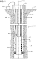
- FIG. 1 an example hydrocarbon development with subterranean well 11 is shown.
- well 11 is shown as a vertical well, embodiments of this disclosure will apply equally to inclined or horizontal wells.
- Well 11 can be lined with a casing 13, or can be free of casing.
- Main tubular 15 can extend within well 11.
- Main tubular 15 is shown concentric around central axis 17 of main tubular 15.
- Main tubular 15 has an open lower end for providing access for production fluids from within subterranean well into main tubular 15.
- Such fluids can include, for example, hydrocarbons in liquid and gas form, and water, as well as solids that are carried by the hydrocarbons and water.
- Outer packer 18 can seal the annular space between the outer diameter of main tubular 15 and the inner diameter of casing 13.
- Production tubular 19 also extends within casing 13.
- Production tubular 19 can be located within, and be circumscribed by, main tubular 15.
- Production tubular 19 can be concentric with main tubular 15 around central axis 17 so that production tubular 19 is coaxially aligned with central axis 17 of main tubular 15 and central axis 17 of main tubular 15 is also a central axis of production tubular 19.
- Production tubular 19 extends to an upper end of subterranean well 11 and can deliver produced fluids to outside of subterranean well 11, such as to the earth's surface 21 by way of wellhead 23.
- main tubular 15 can also extend to an upper end of subterranean well 11 ( Figure 1 ) and in other examples, main tubular 15 may circumscribe only a portion of main tubular 15 and not extend to the upper end of subterranean well 11 ( Figure 2 ).
- the hydrocarbon development of Figure 1 includes a system for separating hydrocarbon fluids from water and solid material within main tubular 15 of subterranean well 11.
- the system for separating hydrocarbon fluids has transducer assembly 25.
- Transducer assembly 25 is located within subterranean well 11.
- Transducer assembly 25 is associated with main tubular 15, but can be located outside of inner diameter 26 of main tubular 15 so that transducer assembly 16 does not interfere with the flow of fluids through main tubular 15 and therefore does not contribute to a pressure drop in the flow of fluids to wellhead 23.
- no system components are located radially inward from production tubular 19, or are radially aligned with the opening of production tubular 19.
- Components located radially inward from production tubular 19 or otherwise radially aligned with the opening of production tubular 19 could restrict access to the wellbore for equipment or tools, such as intervention equipment or logging tools.
- Embodiments disclosed herein provide for uninhibited access to the wellbore through production tubular 19.
- Well 11 can have a single transducer assembly 25, or can have multiple transducer assemblies 25 spaced along the length of well 11.
- transducer assembly 25 is secured to main tubular 15 ( Figure 1 ).
- Transducer assembly 25 can be, for example part of a sidewall of main tubular 15 or secured to the outer diameter of main tubular 15.
- transducer assembly 25 can be part of downhole tool 27 ( Figure 2 ).
- downhole tool 27 can pass over an outer diameter of main tubular 15 so that transducer assembly 25 is located around the outer diameter of main tubular 15.
- downhole tool 27 can be lowered into well 11 upon demand and lifted for routine maintenance or for trouble shooting.
- downhole tool 27 could be utilized as a primary separation tool or as a secondary separation tool after a first separation of the components of the fluids flowing through main tubular is performed by another method or system, such as another transducer assembly 25 or a conventional hydrocyclone or gravity separator. In this way, transducer assembly 25 can be integrated with other downhole oil-water separation techniques to provide a hybrid downhole oil-water separation solution.
- Transducer assembly 25 includes a plurality of piezo electric transducers 29 spaced along a length of main tubular 15.
- the number of piezo electric transducers 29 used in each transducer assembly 25 will vary depending on several operational factors and will be determined based on such operational factors for a particular well 11.
- Such operational factors can include, as an example, flow rate within production tubular 19, the nature and composition of the fluid flowing through production tubular 19, the diameter of main tubular 15, and the temperature and pressure of temperature the fluid flowing through production tubular 19.
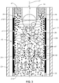
- Piezo electric transducers 29 generate standing acoustic waves 31 ( Figure 3 ) passing through main tubular 15 in a direction transverse to central axis 17.
- Each of the piezo electric transducers 29 generates a standing acoustic wave 31 that has a selected number of loops that is different than the number of loops of adjacent standing acoustic waves 31.
- Piezo electric transducers 29 are aligned and operable to generate standing acoustic waves 31 with a number of loops 33 that decreases in a direction of flow of fluids through main tubular 15.
- the lowermost standing acoustic wave 31A can have a greater number of loops 33 and the uppermost standing acoustic wave 31B can have a lesser number of loops 33.
- a loop is one half of a wave of loops 33.
- uppermost standing acoustic wave 31B is one half of a wave, which is equivalent to a single loop 33.
- Lowermost standing acoustic wave 31A is two waves in length and therefor has four loops 33.
- Each loop 33 has a pressure node 35 at each end of loop 33 and a pressure antinode 37 at a central location of loop 33.
- standing acoustic waves 31 have pressure nodes 35 adjacent to a sidewall of main tubular 15 and have a number of pressure antinodes 37 that is one less than the number of pressure nodes.
- the amplitude of loops 33 and the number of loops 33 of standing acoustic waves 31 will vary depending on several operational factors and will be determined for the operational factors of a particular well 11. Such operational factors can include, as an example, flow rate within production tubular 19, the nature and composition of the fluid flowing through production tubular 19, the diameter of main tubular 15, and the temperature and pressure of temperature the fluid flowing through production tubular 19.
- the number of loops 33 of lowermost standing acoustic wave 31A may be up to twenty.
- the number of loops 33 of uppermost standing acoustic wave 31B can be as low as one, or can be more than one.
- Production tubular 19 is aligned within well 11 so that the lower end of production tubular 19 register with, and is aligned axially above, a pressure antinode 37 of uppermost standing acoustic wave 31B.
- a water conduit 39 can be all or part of the annular space between inner diameter 26 of main tubular 15, and the outer diameter of production tubular 19.
- Water conduit 39 can have an end axially registered with a pressure node 35 of uppermost standing acoustic wave 31B. In the example embodiments shown, water conduit 39 is located adjacent to a sidewall of main tubular 15.
- Solid particle filter 41 can be located within water conduit 39. According to the invention, solid particle filter 41 is aligned with a pressure node 35 of uppermost standing acoustic wave 31B. In alternate examples that do not form part of the present invention, solid particle filter 41 can be located at a different location that does not align with a pressure node 35 of uppermost standing acoustic wave 31B. As an example, solid filter 41 can align with a pressure node 35 of another of the standing acoustic waves 31. As an alternate example, solid filter 41 can be located along a length of water conduit 39 that does not necessarily align with any pressure node 35.
- a communication unit 43 can be in communication with transducer assembly 25.
- Communication unit 43 can be located outside of well 11, such as at the earth's surface 21 so that an operator can utilize communication unit 43.
- Communication unit 43 can include a controller operable to tune standing acoustic waves 31 to adjust the number of loops 33 and amplitude of standing acoustic waves 31.
- the controller of communication unit 43 can communicate with transducer assembly 25 through a wired connection 45, by wireless telemetry, or by other known communication means.
- the operator can utilize communication unit 43 to make changes to the number of loops 33 and amplitude of standing acoustic waves 31 to account for changing operational conditions or production requirements.
- Communication unit 43 can also include a power source in electrical connection with transducer assembly 25.
- the power source can include, for example, a generator and an amplifier.
- transducer assembly 25 is located within well 11.
- transducer assembly 25 being a part of downhole tool 27
- transducer assembly 25 is located within well 11 by lowering downhole tool 27 into well 11.
- transducer assembly 25 is located within well 11 by landing main tubular 15 within well 11.
- the operator can then utilize communication unit 43 to generate standing acoustic waves 31 with piezo electric transducers 29.
- Standing acoustic waves 31 pass through main tubular 15 transverse to central axis 17 and, as will be further discussed in this disclosure, separate the oil from water and solids of the fluids flowing through main tubular 15.
- standing acoustic waves 31 generate primary and secondary acoustic radiation forces that influence oil droplets 47 and solid fines 49 differently due to the difference in their compressibility relevant to water.
- the primary acoustic forces will cause oil droplets 47 to move radially towards pressure antinodes 37 and cause solid fines 49 to move towards pressure nodes 35 of each of the standing acoustic waves 31.
- Oil droplets 47 and solid fines 49 are therefore separated from each in different axial locations along main tubular 15.
- the decreasing number of standing wave loops 33 towards the top of main tubular 15 allows oil droplets 47 to be separated first at the bottom of main tubular 15 forming large ganglia in the center of the tube towards the top where they can be pumped to the surface by way of production tubular 19. Oil droplets 47 will therefore make up a significantly higher portion of the fluids produced to wellhead 23, relative to the concentration of oil droplets 47 in the fluids flowing more generally through main tubular 15. Because production tubular 19 is axially aligned over pressure antinode 37 of uppermost standing acoustic wave 31B, oil droplets 47, which are traveling axially through main tubular 15, will enter production tubular 19 and be produced to wellhead 23.
- the solid fines 49 form large clusters that can be readily filtered out, resulting in a produced clean water with a low fines load that can be injected back into the same formation.
- Water conduit 39 which contains solid particle filter 41, can be axially aligned with a pressure node 35 of uppermost standing acoustic wave 31B.
- a dirty water stream having water and solid fines 49 will enter water conduit 39 where solid fines 49 will be trapped by solid particle filter 41 and removed from the water.
- the resulting clean water can then be produced to the surface or can travel through water injection line 51 to be reinjected downhole. Because the clean water has a low load of solid fines 49, it can be re-injected into the formation without a high risk of pore clogging or formation damage.
- the separation of solid fines 49 from water, solid fines 49 from oil droplets 47, and water from oil droplets 47 can alternately occur at different axial locations within main tubular 15 based upon the tuning of piezo electric transducers 29.
- the location of the separation of components such as the axial location of the removal of solid fines 49, can be optimized for a particular subterranean well 11.
- the removal of solid fines 49 can be accomplished through the use of a removal solids trap at a location other than axially aligned with a pressure node 35 of uppermost standing acoustic wave 31B.
- Systems and method described in this disclosure therefore provide a production flow with increased oil-to-water ratios at the surface as well as reduced solid fines 49 in the water, without obscuring the flow of fluid through main tubular 15, as shown in Figure 51.
- the solid fines 49 and, oil droplet 47 and water will continue to flow steadily towards the earth's surface 21 past piezo electric transducers 29.
- Solid fines 49 will not be separated by settling time, which could hinder the flow of production, but will instead be directed to a separate solid filter 41 by way of water conduit 39 which is parallel to production tubular 19.
- Solid fines 49 can be separated from produced water and captured downhole.
- the injectivity of produced water for re-injection into the formation is increased by increasing the separation efficiency, and thus increasing water quality. This reduces or eliminates the contamination in the produced water pumped to the surface or re-injected into the formation, therefore reducing chemical treatment costs
- Embodiments of this disclosure are adjustable by an operator in real time to accommodate varying water cuts amounts.
- the acoustics can be adjusted to enhance downhole mixing of produced water, if desired.
- System and methods of this disclosure do not require high flow rates to operate and can be used for a large range of flow rates. There are no moving mechanical parts, the system is compact in size and easily installed and operated from the surface, there are minimal maintenance required.
- D is the tube inner diameter
- ⁇ is the wavelength
- n is the harmonic number or number of loops in the standing wave pattern.
- D and ⁇ can have the same units. For example if ⁇ is measured in mm, D will be calculated in mm.
- the standing wave pattern consists of an alternating pattern of pressure nodes and pressure antinodes that are always located at the same positions along the excited medium.
- the standing wave pattern has n pressure antinodes and n+1 pressure nodes.
- subscript p refers to particle or droplet and subscript o refers to the continuous fluid phase (water)
- P 0 is the sound pressure amplitude in N/m2
- V is the volume of a dispersed particle in m 3
- ⁇ is the compressibility in m 2 /N (which is equal to 1/ ⁇ c 2 for liquids; where c is the speed of sound in the liquid in m/s)
- ⁇ is the density in kg/m 3
- z is the distance away from the pressure node in m.
- ⁇ ( ⁇ , ⁇ ) is dependent on the density and compressibility of the dispersed particles relevant to the continuous phase.
- the axial direct radiation force is positive and particles are driven towards the pressure antinodes.
- the contrast factor is positive, the particles are driven towards the pressure nodes.
- Ultrasound of 300 KHz frequency was used for acoustic irradiation of the emulsion/suspension samples in a flat channel microfluidic cell.
- the process was recorded using a high-speed video camera 100 equipped with a Nikon lens for the macroscopic observation or with the high-speed camera 100 attached to an inverted optical microscope 102 for the higher resolution microscopic observation of the process in each of the studied systems.
- the clustering process was characterized in the case of emulsion droplets, solid colloidal particles and ultimately demonstrated the concept for the emulsion droplets separation from the solid particle in the mixtures based on their different acoustic contrast factor.
- the experiment showed that the same approach can be used in a continuous fluid flow process.
- the effectiveness of the acoustic separation for a given particulate dispersed in a medium is determined by the acoustic contrast factor, which is a dimensionless combination of the particulate and medium density and compressibility.
- acoustic contrast factor which is a dimensionless combination of the particulate and medium density and compressibility.
- particulates which are less compressible than the medium, and thereby have a positive acoustic contrast factor are drawn toward the node region of minimum pressure variation
- particulates which are more compressible then the medium, and have a positive acoustic factor are drawn toward the antinode regions of maximum pressure variation.
- Most of the studies conducted so far have used only one type of dispersed particulates, such as solid particles, biological cells, or emulsion droplets.
- the objective of this laboratory work was to use a simple microfluidic flow cell experimental setup to demonstrate the concept of an acoustic separation process for a mixture of components with opposite acoustic contrast factor, and more specifically separation of emulsions droplets and solid particles mixtures.
- the oil-in-water emulsions were prepared by mixing between 1 to 5 wt % of dodecane oil (99.0+%) with deionized water. To stabilize the emulsion 3 ⁇ 10-3 wt % of SPAN® 80 surfactant (Sigma-Aldrich) was added to the dodecane phase resulting in water - oil interfacial tension of about 7 mN/m. A surfactant that is only soluble in the oil phase is preferred to minimize the presence of acoustic bubbles in the emulsion. Two mixing protocols were used to prepare a coarser or a finer sized oil droplets.
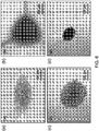
- the coarse size emulsion was prepared by stirring the mixture for 5 minutes at 15000 rpm with a propeller disperser, resulting in oil droplets sizes in the range from 2 ⁇ m to 10 ⁇ m, as seen in Figure 6 .
- the samples were further dispersed using a 20 KHz horn-type-transducer ultrasonic homogenizer. About 5 minutes of pulsating irradiation at 200 Watts resulted in finer emulsion droplet sizes in the range from 1 ⁇ m to 3 ⁇ m, as shown in ( Figure 6b ).
- the emulsion samples were used within 15 minutes following preparation.
- perfluorohexane in the commercial form known as Flutec® PP1 F2 Chemicals Ltd., U.K.
- Flutec® PP1 F2 Chemicals Ltd., U.K.
- the emulsion was stabilized by adding to the water phase 1 ⁇ 10-3 wt% of Zonyl® FSN (DuPont) which is a nonionic fluorosurfactant that modifies the interfacial energies at very low concentrations.
- Zonyl® FSN DuPont
- silica particles suspensions of sizes 0.15 ⁇ m, 0.5 ⁇ m, 1.2 ⁇ m and 7.5 ⁇ m as 5 wt% aqueous suspensions were obtained. Before use, the silica particles were washed from the original suspension solution to remove surfactant traces. The standard concentration of silica microparticle in the deionized water suspension used was 1 wt % if not otherwise specified.
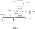
- Figure 4 shows a schematic of the experimental setup used to conduct the macroscopic and microscopic observations of the ultrasonic irradiation in the microfluidic cell.
- the transducer 106 was powered using a 20 MHz function/arbitrary waveform generator, and a DC to 1 MHz high speed bipolar amplifier.
- the transducer was operated using a standard setting of 300 kHz, with sinusoidal signal of 1 V amplitude from the signal generator, giving about 40 Volts amplifier output signal.
- the resonance frequency of the transducer was chosen so that the dimension of the cell will be a few times the wavelength, which makes it convenient for observations with the experimental setup.
- the cell was mounted on the observation stage of an inverted microscope 102.
- a high-speed video camera 100a was attached to the side port of the microscope allowing recording of bottom view observations of the irradiation process using 10 ⁇ , 20 ⁇ , or 40 ⁇ magnification objectives.
- the high-speed camera 100b equipped with an 85 mm lens was mounted on a vertical rail at a focal distance of about 20 cm above the cell, for the top-view macroscopic observation of the irradiation process over the entire cell.
- the cell inlet is connected by plastic tubing to a 10 ml syringe 108 used to introduce the studied solutions into the cell. Most of the experiments were done at static flow conditions by sealing the inlet and outlet tubing after the cell is filled with the solution. Controlled flow experiments were accomplished by mounting the syringe to an automated syringe pump.
- the acoustic radiation forces tend to be dominant for larger particulate sizes (> 1 ⁇ m) and lower irradiation frequencies ( ⁇ 1 MHz), and the streaming force is more pronounced for smaller particle sizes ( ⁇ 1 ⁇ m) but higher acoustic frequencies (> 1 MHz).
- the primary acoustic radiation force arises from the spatial gradient of the acoustic wave pressure.
- ⁇ is the density in kg/m 3
- ⁇ is the compressibility in m 2 /N
- the subscripts p refers to the particulate (emulsion droplet or colloidal particle) and m to the medium.
- a particulate with positive acoustic contrast factor When subject to a standing acoustic wave field a particulate with positive acoustic contrast factor experiences a primary acoustic radiation force that drives it toward the pressure nodes in the acoustic field, e.g. zones with minimum pressure amplitude variation. Reversely, particulates with negative acoustic contrast factor are driven toward the antinodes in the acoustic field, which have maximum pressure variation.
- Table 1 gives the specific density and speed of sound for the particulates droplets used in our study (dodecane droplets, perfluorohexane droplets, and silica colloidal particles) and their respective acoustic contrast factor when dispersed in water medium.
- Dodecane and perfluorohexane droplets have a negative acoustic contrast factor, and the silica particles have a positive acoustic contrast factor when dispersed in water medium.
- Table 1 Density, speed of sound and acoustic contrast factors of the studied medium and particulates . ⁇ [kg/m 3 ] c [m/s] ⁇ (in water) Water 1000 1497 Dodecane 800 1260 - 0.83 Perfluorohexane 1700 480 - 7.12 Silica 2400 5640 + 2.20
- the secondary radiation force arises from the acoustic field reflection from the suspended particles and becomes significant once the particles are brought closer together.
- the secondary radiation force depends on the position of the particles with respect to the acoustic wave propagation direction. The force is repulsive between particles in the direction perpendicular to the wave front propagation but attractive in direction along the wave front propagation.
- acoustic streaming is also induced on the suspended particles. Streaming arises because of the dissipation process in the fluid phase and in the fluid - solid interface. There are several types of streaming which are pronounced at different length scales: large scale Eckart steaming (scale >> ⁇ ) and small scale Rayleigh (scale ⁇ ⁇ ) and Schlichting (scale ⁇ ) streaming. In the context of the present experiment the most significant is expected to be the Rayleigh-scale streaming.
- Figure 5 shows snapshots as an example for the top-view macroscopic observations of the acoustic irradiation process in the case of fine dodecane oil droplets in water emulsion.
- Figure 5b Several seconds after the initiation of the ultrasonication the formation of dark spots connected by thin lines were observed, indicating the formation of emulsion droplet clusters ( Figure 5b ).
- the thin lines gradually fade and about 5 minutes after the start of the irradiation discrete dark spots pattern is observed ( Figure 5c ).
- this type of experiment can be used as a simple method to visualize the acoustic filled pressure distribution in the cell, as alternative to particle image velocimetry (PIV) imaging.
- PV particle image velocimetry
- the pressure antinode positions are close to the cell side walls, with three more lines of anti-nodes fitting in the space between.
- the position of the anti-nodes is slightly disordered because the shape of the cell is not an exact resonant cavity, but having curved end walls. Nevertheless the expected characteristic spacing of ⁇ /2 between the cluster structures can be clearly observed.
- Figure 5 shows top-view macroscopic observations for the acoustic separation in the case of fine dodecane droplets in water emulsion: (a) before the start of the ultrasonic irradiation, (b) 40 seconds and (c) 600 seconds after the beginning of the irradiation.
- Figure 6 includes microscopic observations showing high-speed video snapshots where: (a) shows the cluster formation for the case of coarse dodecane emulsion droplets; (b) shows a high concentration fine droplets size dodecane emulsion; (c) shows an emulsion droplet cluster deposited on the cell surface at switch-off; and (d) shows an emulsion droplet cluster levitated in the pressure antinode upon the switching-on of the ultrasound.
- Figure 7 shows a few cycles of cluster relaxation ( Fig 7c ) and cluster aggregation in the pressure anti-node (Figure 7d) upon the switching on the ultrasound.
- the neighboring clusters tend to migrate toward each other and the final pattern is of elongated shape clusters that are more sparsely separated along the cell length.
- the final distance between the clusters positions is about 2.5 mm ⁇ ⁇ /2 in direction perpendicular to channel transverse axis, but closer to 5.0 mm, or ⁇ ⁇ in the direction along the channel length.
- Figure 7 therefore illustrates snapshots from top-view macroscopic view for the separation process in the case of case 1 wt % 7.5 ⁇ m silica particles: (a) 15 seconds; and (b) 150 seconds after the beginning of the ultrasonication.
- Figure 7c illustrates the dynamic clustering pattern observed in the case of 5 wt % 7.5 ⁇ m silica particles case.
- Figure 9 shows microscopic high-speed observation for the various silica particles sizes.
- Figures 9a and 9b are examples for a small and a large cluster of 7.5 ⁇ m silica particle aggregates.
- the 7.5 microns clusters have well pronounced parallel strings of particles. The formation of these particle strings can be explained by the action of secondary acoustic radiation forces.
- Figures 9c and 9d are examples of 1.2 ⁇ m silica particles clusters.
- a distinct string sub-structure of the cluster is observed similar to the case of 7.5 ⁇ m particles.
- this order could be lost and a vortex type cluster develops as demonstrated in Figure 9d .
- Figure 9e shows a vortex structure core observed after about 5 minutes of irradiation in the case of 0.5 ⁇ m silica particles, indicating that for that particle size the acoustic clustering is still possible but is now dominated by the streaming acoustic forces.
- Figure 9f shows the case of 0.15 ⁇ m particle suspension after 10 minutes of irradiation.
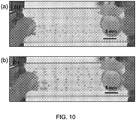
- the difference between the emulsion droplets and silica particle clusters can be even more clearly observed shortly after the ultrasonication is interrupted and buoyancy separated the two as shown in Figure 10b .
- the darker round spots are the emulsion droplet clusters deposited at the upper wall of the cell and the lighter intensity elliptic spots are the silica particle clusters deposited at the bottom of the cell.
- the approximate spacing between two droplet clusters or between two particle clusters is close to the spacing between those clusters in the case of a single component solution.
- the positions of the clusters in the mixture case is not an exact superposition of the single components cluster positions ( Figure 5c and Figure 5b ), implying a certain degree of interplay between the emulsion droplets and silica particle clusters.
- FIG. 12a is a snapshot for the case of coarse emulsion droplets and 7.5 ⁇ m silica particles cluster
- Figure 12b is a snapshot for the case of the fine emulsion droplets and 1.2 ⁇ m silica particles.
- the average distance between the silica particle and dodecane droplets cluster shown in these figures is about 1.1 mm close to, but not exactly equal the expected ⁇ /4 spacing between the node and antinodes positions, which is about 1.25 mm. This confirms the macroscopic observation of some degree of interplay between the clusters.
- the emulsion droplet and silica particle clusters have similar sub-structures to the one observed for the single components cases.
- the videos that were recorded show a more complex dynamical interaction with the particles and droplets circulating are reflected between the clusters, even in the case of larger particulates and more pronounced for smaller particulates due to the stronger involvement of the vortex forming streaming forces.
- Figure 12 shows microscopic high-speed video snapshots taken using a 10 ⁇ objective showing separate clustering of silica particle and dodecane droplets during the mixtures irradiation.
- Figure 12a shows a 7.5 ⁇ m silica particle cluster on left and a coarse dodecane droplets cluster on right.
- Figure 12b shows 1.2 ⁇ m silica particle clusters on left and fine dodecane droplets cluster on right.
- Figure 12c shows 1.2 ⁇ m silica particles on the left and fine perfluorohexane droplets cluster on the right.
- FIG 11b the case of a mixture of emulsion droplets and silica particles is presented.
- seven lines formed along the cell length streaming toward the outlet.
- Three of them are emulsion droplets streams going through the antinodes positions and four are concentrated silica particles streams passing through the respective pressure-node positions along the cell, as arrowed in Figure 11b .
- the microfluidic cell used here was not specifically designed for the collection of the concentrated emulsion droplet and silica particles streams at the cell outlet. Nevertheless these preliminary experiments demonstrate the potential for the operation of microfluidic devices in constant flow mode to separate components from a mixture of particulates with different acoustic-contrast.
- Figure 11 shows acoustic separation in a continuous-flow illustrating microfluidic system.
- Figure 11a shows dodecane droplets emulsion. Three streams of droplets passing along the antinode positions during the 5 mm/second fluid flow phase.
- Figure 11b shows a dodecane droplets and 7.5 ⁇ m silica particle mixture. The four wider streams of silica particles and three lighter colored streams of dodecane droplets at the node and antinode planes respectively.
- the model system was aqueous solutions of dodecane oil emulsion droplets and silica colloidal particles.
- the cell dimensions combined with the selection of a 300 KHz resonant frequency piezo electric transducer allow for macroscopic observations that characterize the acoustic field distribution in the cell, combined with additional detailed microscopic observations of the particulates clustering process. Initially the separation process was characterized as a single particulate or droplet type.
- Embodiments of this disclosure therefore provide both financial and environmental advantages over some known hydrocarbon production systems, such as: reducing the volume of produced water and necessary surface facilities for handling produced water; reducing the amount of corrosion and scale accumulated on production pipes over time; the reduction of the number of disposal wells to be drilled; and the reduction of risks associated with injecting contaminated water into the formation.
- Embodiments of the systems and methods described in this disclosure are well adapted to carry out the objects and attain the ends and advantages mentioned, as well as others inherent in embodiments described in this disclosure. While example embodiments of the disclosure have been given for purposes of disclosure, numerous changes exist in the details of procedures for accomplishing the desired results.
Landscapes
- Engineering & Computer Science (AREA)
- Life Sciences & Earth Sciences (AREA)
- Geology (AREA)
- Mining & Mineral Resources (AREA)
- Environmental & Geological Engineering (AREA)
- Physics & Mathematics (AREA)
- Fluid Mechanics (AREA)
- General Life Sciences & Earth Sciences (AREA)
- Geochemistry & Mineralogy (AREA)
- Chemical & Material Sciences (AREA)
- Mechanical Engineering (AREA)
- Thermal Sciences (AREA)
- Chemical Kinetics & Catalysis (AREA)
- Hydrology & Water Resources (AREA)
- Water Supply & Treatment (AREA)
- Organic Chemistry (AREA)
- Physical Or Chemical Processes And Apparatus (AREA)
Claims (14)
- Verfahren zum Trennen von Kohlenwasserstofffluiden von Wasser und festem Material innerhalb eines Hauptrohrs (15) einer unterirdischen Bohrung (11), wobei das Hauptrohr (15) eine mittlere Achse (17) besitzt, wobei das Verfahren Folgendes beinhaltet:Positionieren einer Umformeranordnung (25) innerhalb der unterirdischen Bohrung (11), wobei die Umformeranordnung (25) eine Vielzahl von piezoelektrischen Umformern (29) umfasst, welche entlang einer Länge des Hauptrohrs (15) beabstandet ist;Erzeugen von stehenden akustischen Wellen (31) mit der Vielzahl von piezoelektrische Umformern (29), wobei die stehenden akustischen Wellen (31) durch das Hauptrohr (15) quer zur mittleren Achse (17) passieren; wobei eine Anzahl von Schleifen (33) der stehenden akustischen Wellen (31) in einer Strömungsrichtung von Fluiden durch das Hauptrohr (15) abnimmt;Bereitstellen eines Förderrohrs (19) in dem unterirdischen Bohrloch (11), wobei ein Ende des Förderrohrs (19) mit einem Druckschwingungsbauch (37) einer obersten stehenden akustischen Welle (31B) gefluchtet ist;Fluchten eines Filters für feste Partikel (41) mit einem Druckknoten (35) der obersten stehenden akustischen Welle (31B) zum Filtern fester Partikel aus einem Schmutzwasserstrom zum Bilden eines reinen Wassers.
- Verfahren nach Anspruch 1, bei welchem:(i) die Umformeranordnung (25) außerhalb eines Innendurchmessers (26) des Hauptrohrs (15) positioniert ist; und/oder(ii) der Schritt des Erzeugens von stehenden akustischen Wellen (31) Bereitstellen von Strom an die Umwandleranordnung (25) von einer Stromquelle außerhalb des unterirdischen Bohrlochs (11) umfasst.
- Verfahren nach einem der Ansprüche 1 bis 2, bei welchem eine mittlere Achse (17) des Förderrohrs (19) koaxial mit der mittleren Achse (17) des Hauptrohrs (15) gefluchtet ist.
- Verfahren nach einem der Ansprüche 1 bis 3, wobei das Verfahren zudem Injizieren von reinem Wasser in eine Kohlenwasserstoffformation beinhaltet.
- Verfahren nach einem der Ansprüche 1 bis 4, bei welchem der Schritt des Erzeugens von stehenden akustischen Wellen (31) Erzeugen von stehenden akustischen Wellen (31) mit Druckknoten (35) umfasst, welche an eine Seitenwand des Hauptrohrs (15) angrenzen und eine Anzahl von Druckschwingungsbäuchen (37) aufweisen, welche um eine Einheit geringer als die Anzahl der Drucknoten (35) ist; wobei wahlweise das Verfahren zudem das Fluchten des Filters für feste Partikel (41) mit einem Druckknoten (35) der obersten stehenden akustischen Welle (31B), welche an die Seitenwand des Hauptförderrohrs (15) angrenzt, um feste Partikel aus dem Schmutzwasserstrom zum Bilden des reinen Wassers zu filtern, beinhaltet.
- Verfahren nach einem der Ansprüche 1 bis 5, bei welchem der Schritt des Positionierens der Umformeranordnung (25) innerhalb des unterirdischen Bohrlochs (11) Folgendes beinhaltet:(i) Absenken eines Bohrlochwerkzeugs (27), welches die Umformeranordnung (25) aufweist, in das unterirdische Bohrloch (11); oder(ii) Aufsetzen des Hauptförderrohrs (15) innerhalb des unterirdischen Bohrlochs (11), wobei die Umformeranordnung (25) am Hauptförderrohr (15) gesichert ist.
- Verfahren nach Anspruch 1, zudem beinhaltend:Abstimmen der stehenden akustischen Wellen (31) mit einem Steuergerät außerhalb unterirdischen Bohrlochs (11), zum Anpassen der Anzahl von Schleifen (33) und der Amplitude der stehenden akustischen Wellen (31).
- Verfahren nach Anspruch 1, bei welchem:(i) das Verfahren zudem Bereitstellen einer Wasserleitung (39) in dem unterirdischen Bohrloch (11) beinhaltet, wobei die Wasserleitung (39) ein axiales mit dem Druckknoten (35) der obersten stehenden akustischen Welle (31B) deckungsgleiches Ende aufweist; und/oder(ii) der Schritt des Erzeugens von stehenden akustischen Wellen (31) Erzeugen von stehenden akustischen Wellen (31) mit Druckschwingungsbäuchen (37) umfasst, welche an eine Seitenwand des Hauptrohrs (15) angrenzen und eine Anzahl von Druckknoten aufweisen, welche um eine Einheit geringer als eine Anzahl von Druckschwingungsbäuchen (37) ist.
- System zum Trennen von Kohlenwasserstofffluiden von Wasser und festem Material innerhalb eines Hauptrohrs (15) einer unterirdischen Bohrung (11), wobei das Hauptrohr (15) eine mittlere Achse (17) besitzt, wobei das System Folgendes beinhaltet:ein Förderrohr (19), welches in dem unterirdischen Bohrloch (11) positioniert ist;einen Filter für feste Partikel (41) in dem unterirdischen Bohrloch (11); undeine Umformeranordnung (25), welche innerhalb der unterirdischen Bohrung (11) positioniert ist, wobei die Umformeranordnung (25) eine Vielzahl von piezoelektrischen Umformern (29) umfasst, welche entlang einer Länge des Hauptrohrs (15) beabstandet ist; wobeidie piezoelektrischen Umformer (29) positioniert sind, um stehende akustische Wellen (31) zu erzeugen, welche durch das Hauptrohr (15) in einer quer zur mittleren Achse (17) liegenden Richtung passieren;wobei die piezoelektrischen Umformer (29) gefluchtet und bedienbar sind, um stehende akustische Wellen (31) mit einer Anzahl an Schleifen (33) zu erzeugen, welche in einer Strömungsrichtung von Fluiden durch das Hauptrohr (15) abnimmt;wobei ein Ende des Förderrohrs (19) mit einem Druckschwingungsbauch (37) einer obersten stehenden akustischen Welle (31 B) gefluchtet ist; undwobei der Filter für feste Partikel (41) mit einem Druckknoten (35) der obersten stehenden akustischen Welle (31B) gefluchtet und bedienbar ist, um ein reines Wasser zur Injektion in eine Kohlenwasserstoffformation zu produzieren.
- System nach Anspruch 9, bei welchem die Umformeranordnung (25) außerhalb eines Innendurchmessers (26) des Hauptrohrs (15) positioniert ist.
- System nach Anspruch 9 oder Anspruch 10, zudem Folgendes beinhaltend:
eine Stromquelle, welche außerhalb des unterirdischen Bohrlochs (11) positioniert ist und in elektrischer Verbindung mit der Umformeranordnung (25) steht. - System nach Anspruch 9 oder Anspruch 10, bei welchem eine mittlere Achse (17) des Förderrohrs (19) koaxial mit der mittleren Achse (17) des Hauptrohrs (15) gefluchtet ist.
- System nach einem der Ansprüche 9 bis 12, bei welchem:(i) das System zudem ein Bohrlochwerkzeug (27) beinhaltet, wobei das Bohrlochwerkzeug (27) die Umformeranordnung (25) aufweist; oder(ii) die Umformeranordnung (25) an dem Hauptrohr (15) gesichert ist.
- System nach einem der Ansprüche 9 bis 13, zudem beinhaltend:(i) ein Steuergerät, welches bedienbar ist, um die stehenden akustischen Wellen (31) abzustimmen, um die Anzahl von Schleifen (33) und die Amplitude der stehenden akustischen Wellen (31) anzupassen, wobei das Steuergerät außerhalb des unterirdischen Bohrlochs (11) positioniert ist; und/oder(ii) eine Wasserleitung (39), welche in dem unterirdischen Bohrloch (11) positioniert ist, wobei die Wasserleitung (39) ein axiales mit dem Druckknoten (35) der obersten stehenden akustischen Welle (31B) deckungsgleiches Ende aufweist; wobei wahlweise die Wasserleitung (39) an eine Seitenwand des Hauptrohrs (15) angrenzt.
Applications Claiming Priority (2)
| Application Number | Priority Date | Filing Date | Title |
|---|---|---|---|
| US201562267991P | 2015-12-16 | 2015-12-16 | |
| PCT/US2016/066826 WO2017106441A1 (en) | 2015-12-16 | 2016-12-15 | Acoustic downhole oil-water separation |
Publications (2)
| Publication Number | Publication Date |
|---|---|
| EP3390776A1 EP3390776A1 (de) | 2018-10-24 |
| EP3390776B1 true EP3390776B1 (de) | 2020-03-11 |
Family
ID=57708847
Family Applications (1)
| Application Number | Title | Priority Date | Filing Date |
|---|---|---|---|
| EP16820515.1A Active EP3390776B1 (de) | 2015-12-16 | 2016-12-15 | Akustische öl-wasser-trennung in einem im bohrloch |
Country Status (5)
| Country | Link |
|---|---|
| US (1) | US11053788B2 (de) |
| EP (1) | EP3390776B1 (de) |
| CN (1) | CN108368737B (de) |
| CA (1) | CA3005477C (de) |
| WO (1) | WO2017106441A1 (de) |
Families Citing this family (31)
| Publication number | Priority date | Publication date | Assignee | Title |
|---|---|---|---|---|
| US10967298B2 (en) | 2012-03-15 | 2021-04-06 | Flodesign Sonics, Inc. | Driver and control for variable impedence load |
| US9752113B2 (en) | 2012-03-15 | 2017-09-05 | Flodesign Sonics, Inc. | Acoustic perfusion devices |
| US9950282B2 (en) | 2012-03-15 | 2018-04-24 | Flodesign Sonics, Inc. | Electronic configuration and control for acoustic standing wave generation |
| US9458450B2 (en) | 2012-03-15 | 2016-10-04 | Flodesign Sonics, Inc. | Acoustophoretic separation technology using multi-dimensional standing waves |
| US10322949B2 (en) | 2012-03-15 | 2019-06-18 | Flodesign Sonics, Inc. | Transducer and reflector configurations for an acoustophoretic device |
| US10704021B2 (en) | 2012-03-15 | 2020-07-07 | Flodesign Sonics, Inc. | Acoustic perfusion devices |
| US10689609B2 (en) | 2012-03-15 | 2020-06-23 | Flodesign Sonics, Inc. | Acoustic bioreactor processes |
| US9745548B2 (en) | 2012-03-15 | 2017-08-29 | Flodesign Sonics, Inc. | Acoustic perfusion devices |
| US10737953B2 (en) | 2012-04-20 | 2020-08-11 | Flodesign Sonics, Inc. | Acoustophoretic method for use in bioreactors |
| US9745569B2 (en) | 2013-09-13 | 2017-08-29 | Flodesign Sonics, Inc. | System for generating high concentration factors for low cell density suspensions |
| WO2015105955A1 (en) | 2014-01-08 | 2015-07-16 | Flodesign Sonics, Inc. | Acoustophoresis device with dual acoustophoretic chamber |
| US9744483B2 (en) | 2014-07-02 | 2017-08-29 | Flodesign Sonics, Inc. | Large scale acoustic separation device |
| US11021699B2 (en) | 2015-04-29 | 2021-06-01 | FioDesign Sonics, Inc. | Separation using angled acoustic waves |
| US11708572B2 (en) | 2015-04-29 | 2023-07-25 | Flodesign Sonics, Inc. | Acoustic cell separation techniques and processes |
| US11377651B2 (en) | 2016-10-19 | 2022-07-05 | Flodesign Sonics, Inc. | Cell therapy processes utilizing acoustophoresis |
| US11474085B2 (en) | 2015-07-28 | 2022-10-18 | Flodesign Sonics, Inc. | Expanded bed affinity selection |
| US11459540B2 (en) | 2015-07-28 | 2022-10-04 | Flodesign Sonics, Inc. | Expanded bed affinity selection |
| JP2019507681A (ja) | 2016-03-06 | 2019-03-22 | ヴィント プルス ゾンネ ゲー・エム・ベー・ハーWind plus Sonne GmbH | 音響泳動により、エアロゾルと、ガスからの固形物粒子および繊維と、流体からの固形物粒子および繊維とを分離および/または清浄化するための方法および機器 |
| US11085035B2 (en) | 2016-05-03 | 2021-08-10 | Flodesign Sonics, Inc. | Therapeutic cell washing, concentration, and separation utilizing acoustophoresis |
| US11214789B2 (en) | 2016-05-03 | 2022-01-04 | Flodesign Sonics, Inc. | Concentration and washing of particles with acoustics |
| WO2018075830A1 (en) | 2016-10-19 | 2018-04-26 | Flodesign Sonics, Inc. | Affinity cell extraction by acoustics |
| US20180363441A1 (en) * | 2017-06-19 | 2018-12-20 | Azra N. Tutuncu | Method and apparatus for improving wellbore productivity with piezoelectric crystals |
| KR102439221B1 (ko) | 2017-12-14 | 2022-09-01 | 프로디자인 소닉스, 인크. | 음향 트랜스듀서 구동기 및 제어기 |
| DE102018008259A1 (de) * | 2018-10-18 | 2020-04-23 | Smart Material Printing B.V. | Filteranlagen für Schwebstoffe mit Teilchengrößen von 400 pm bis ≤500 μm und ihre Verwendung |
| RU191314U1 (ru) * | 2019-03-14 | 2019-08-01 | федеральное государственное автономное образовательное учреждение высшего образования "Российский университет дружбы народов" (РУДН) | Гидроциклон с камерой |
| US11162348B2 (en) | 2019-10-17 | 2021-11-02 | Halliburton Energy Services, Inc. | Methods to improve fluid flow of a multi-phase mixture, methods to separate fluids of a multi-phase mixture, and multi-phase fluid mixture systems |
| CN112316500B (zh) * | 2020-09-30 | 2022-03-01 | 中国石油天然气股份有限公司 | 一种超声波旋流分离装置 |
| US11291939B1 (en) | 2021-07-13 | 2022-04-05 | Smart Material Printing B.V. | Ultra-fine particle aggregation, neutralization and filtration |
| GB202118030D0 (en) * | 2021-12-13 | 2022-01-26 | Sulnox Group Llc | Fuel oil reclamation |
| US12005388B2 (en) | 2022-07-26 | 2024-06-11 | Smart Material Printing B.V. | Apparatus and methods for air filtration of HVAC systems |
| US12497883B2 (en) | 2023-11-06 | 2025-12-16 | Saudi Arabian Oil Company | Increasing hydrocarbon recovery in a multipurpose well |
Citations (1)
| Publication number | Priority date | Publication date | Assignee | Title |
|---|---|---|---|---|
| US20060037915A1 (en) * | 2002-06-04 | 2006-02-23 | Protasis Corporation | Method and device for ultrasonically manipulating particles within a fluid |
Family Cites Families (25)
| Publication number | Priority date | Publication date | Assignee | Title |
|---|---|---|---|---|
| US3534816A (en) * | 1968-10-22 | 1970-10-20 | Union Oil Co | Method and apparatus for completing a well in vertically spaced porous strata |
| USH568H (en) * | 1985-03-19 | 1989-01-03 | Shell Oil Company | Olefin polymer composition and laminated structure including said composition as adhesive layer |
| AT389235B (de) | 1987-05-19 | 1989-11-10 | Stuckart Wolfgang | Verfahren zur reinigung von fluessigkeiten mittels ultraschall und vorrichtungen zur durchfuehrung dieses verfahrens |
| US4960525A (en) | 1988-09-26 | 1990-10-02 | The United States Of America, As Represented By The Secretary Of Agriculture | Hydrocyclone for washing particles in liquid suspension |
| US5344532A (en) | 1990-03-09 | 1994-09-06 | Joseph Adrian A | Ultrasonic energy producing device |
| DE4204990C2 (de) | 1992-02-19 | 1994-01-27 | Ieg Ind Engineering Gmbh | Verfahren und Anordnung zum Ausbringen von in Erd- oder Gesteinsschichten gehaltenen Flüssigkeiten und/oder Gasen, insbesondere von Öl |
| USH1568H (en) * | 1994-05-26 | 1996-08-06 | Exxon Production Research Company | Acoustic separation of liquid hydrocarbons from wastewater |
| US5996690A (en) | 1995-06-06 | 1999-12-07 | Baker Hughes Incorporated | Apparatus for controlling and monitoring a downhole oil/water separator |
| GB9519339D0 (en) | 1995-09-22 | 1995-11-22 | Vortoil Separation Systems Ltd | A method of separating production fluid from an oil well |
| US5740860A (en) * | 1996-04-08 | 1998-04-21 | Crawford; William B. | Side pocket mandrel for a measuring instrument |
| US6336503B1 (en) | 2000-03-03 | 2002-01-08 | Pancanadian Petroleum Limited | Downhole separation of produced water in hydrocarbon wells, and simultaneous downhole injection of separated water and surface water |
| SE522801C2 (sv) | 2001-03-09 | 2004-03-09 | Erysave Ab | Anordning för att separera suspenderade partiklar från en fluid med ultraljud samt metod för sådan separering |
| US7766121B2 (en) | 2005-12-20 | 2010-08-03 | Cyclotech Limited | Methods and apparatus for conditioning and degassing liquids and gases in suspension |
| US20090065431A1 (en) * | 2006-02-20 | 2009-03-12 | Knut Bakke | In-line separator |
| CN100460626C (zh) * | 2006-06-22 | 2009-02-11 | 桑玉元 | 超声波原油、气、沙分离装置 |
| US7807454B2 (en) * | 2006-10-18 | 2010-10-05 | The Regents Of The University Of California | Microfluidic magnetophoretic device and methods for using the same |
| RU2392422C1 (ru) * | 2009-04-28 | 2010-06-20 | Общество С Ограниченной Ответственностью "Соновита" | Способ добычи нефти с использованием энергии упругих колебаний и установка для его осуществления |
| EP2558179B1 (de) | 2010-04-12 | 2020-08-05 | Flodesign Sonics Inc. | Verwendung von ultraschall- und akustophoresetechnologie zur trennung von partikeln aus einem tragenden medium |
| RU2531984C2 (ru) | 2010-06-30 | 2014-10-27 | Шлюмбергер Текнолоджи Б.В. | Разделение нефти, воды и твердых частиц внутри скважины |
| PL2612140T3 (pl) | 2010-09-03 | 2017-10-31 | Los Alamos Nat Security Llc | Zintegrowany, akustyczny separator faz i urządzenie oraz sposób monitorowania wielofazowej, płynnej kompozycji |
| WO2012135663A2 (en) | 2011-03-31 | 2012-10-04 | University Of South Florida | Two-stage microfluidic device for acoustic particle manipulation and methods of separation |
| US10040011B2 (en) * | 2012-03-15 | 2018-08-07 | Flodesign Sonics, Inc. | Acoustophoretic multi-component separation technology platform |
| BR112015013599A2 (pt) * | 2012-12-11 | 2017-07-11 | Halliburton Energy Services Inc | aparelho de filtragem de fluido de hidrocarboneto, e, método para produzir hidrocarbonetos fluidos filtrados |
| WO2015107014A1 (en) | 2014-01-15 | 2015-07-23 | Eth Zurich | Acoustophoretic droplet handling in bulk acoustic wave devices |
| US10047596B2 (en) * | 2015-07-23 | 2018-08-14 | General Electric Company | System and method for disposal of water produced from a plurality of wells of a well-pad |
-
2016
- 2016-12-08 US US15/373,108 patent/US11053788B2/en active Active
- 2016-12-15 WO PCT/US2016/066826 patent/WO2017106441A1/en not_active Ceased
- 2016-12-15 CA CA3005477A patent/CA3005477C/en active Active
- 2016-12-15 CN CN201680074393.8A patent/CN108368737B/zh active Active
- 2016-12-15 EP EP16820515.1A patent/EP3390776B1/de active Active
Patent Citations (1)
| Publication number | Priority date | Publication date | Assignee | Title |
|---|---|---|---|---|
| US20060037915A1 (en) * | 2002-06-04 | 2006-02-23 | Protasis Corporation | Method and device for ultrasonically manipulating particles within a fluid |
Also Published As
| Publication number | Publication date |
|---|---|
| CN108368737B (zh) | 2021-04-16 |
| CA3005477C (en) | 2022-03-01 |
| CA3005477A1 (en) | 2017-06-22 |
| EP3390776A1 (de) | 2018-10-24 |
| US20170175509A1 (en) | 2017-06-22 |
| WO2017106441A1 (en) | 2017-06-22 |
| US11053788B2 (en) | 2021-07-06 |
| CN108368737A (zh) | 2018-08-03 |
Similar Documents
| Publication | Publication Date | Title |
|---|---|---|
| EP3390776B1 (de) | Akustische öl-wasser-trennung in einem im bohrloch | |
| Agi et al. | Intermittent ultrasonic wave to improve oil recovery | |
| US10071383B2 (en) | High-volume fast separation of multi-phase components in fluid suspensions | |
| AU696770B2 (en) | Method for extracting oil from oil-contaminated soil | |
| USH1568H (en) | Acoustic separation of liquid hydrocarbons from wastewater | |
| CN104692605B (zh) | 一种含油污泥减量化处理方法及其装置 | |
| US8158000B2 (en) | System and method of separating hydrocarbons | |
| RU2136859C1 (ru) | Способ разработки нефтяных месторождений | |
| US20150138924A1 (en) | Acoustic fracturing of rock formations | |
| US20150138923A1 (en) | Acoustic cavitation in fluids | |
| Taheri-Shakib et al. | Application of ultrasonic as a novel technology for removal of inorganic scales (KCl) in hydrocarbon reservoirs: An experimental approach | |
| US20180154282A1 (en) | Method and device for separation of liquids and gas with use of inclined and rounded holes or channels in the wall of a pipe | |
| MX2012010403A (es) | Sistema y metodo para separar los solidos de los fluidos. | |
| EP2882926B1 (de) | Verfahren und vorrichtung zur trennung von bohr-und abschlussflüssigkeit | |
| US2816612A (en) | Device for cleaning well perforations | |
| US20230087629A1 (en) | Method and system for solid particle removal | |
| Abdel-Fattah | Acoustic downhole oil/water/fines separation (ADOWFs) | |
| RU2281387C2 (ru) | Способ воздействия на флюид нефтяных месторождений при добыче нефти | |
| RU2215126C2 (ru) | Способ восстановления и поддержания продуктивности скважины | |
| CN103086455B (zh) | 油田污水处理设备 | |
| Khalde et al. | Computational and experimental study of sand entrapment in a hydrocyclone during desanding operations in oil fields: consequences for leakage and separation efficiency | |
| CA2950145A1 (en) | Transverse flow microfiltration of solids from fluids with inserts | |
| Vedmenskiy et al. | The acoustic oscillation effect on the saturated pore-medium filtration characteristics with the purpose of oil recovery improvement and intensification of the flow | |
| EP3570958A1 (de) | Verfahren und system zur entfernung von festen teilchen | |
| WO1995034522A1 (en) | Method and apparatus for breaking hydrocarbon emulsions |
Legal Events
| Date | Code | Title | Description |
|---|---|---|---|
| STAA | Information on the status of an ep patent application or granted ep patent |
Free format text: STATUS: UNKNOWN |
|
| STAA | Information on the status of an ep patent application or granted ep patent |
Free format text: STATUS: THE INTERNATIONAL PUBLICATION HAS BEEN MADE |
|
| PUAI | Public reference made under article 153(3) epc to a published international application that has entered the european phase |
Free format text: ORIGINAL CODE: 0009012 |
|
| STAA | Information on the status of an ep patent application or granted ep patent |
Free format text: STATUS: REQUEST FOR EXAMINATION WAS MADE |
|
| 17P | Request for examination filed |
Effective date: 20180525 |
|
| AK | Designated contracting states |
Kind code of ref document: A1 Designated state(s): AL AT BE BG CH CY CZ DE DK EE ES FI FR GB GR HR HU IE IS IT LI LT LU LV MC MK MT NL NO PL PT RO RS SE SI SK SM TR |
|
| AX | Request for extension of the european patent |
Extension state: BA ME |
|
| STAA | Information on the status of an ep patent application or granted ep patent |
Free format text: STATUS: EXAMINATION IS IN PROGRESS |
|
| DAV | Request for validation of the european patent (deleted) | ||
| DAX | Request for extension of the european patent (deleted) | ||
| 17Q | First examination report despatched |
Effective date: 20190321 |
|
| GRAP | Despatch of communication of intention to grant a patent |
Free format text: ORIGINAL CODE: EPIDOSNIGR1 |
|
| STAA | Information on the status of an ep patent application or granted ep patent |
Free format text: STATUS: GRANT OF PATENT IS INTENDED |
|
| INTG | Intention to grant announced |
Effective date: 20191122 |
|
| GRAS | Grant fee paid |
Free format text: ORIGINAL CODE: EPIDOSNIGR3 |
|
| GRAA | (expected) grant |
Free format text: ORIGINAL CODE: 0009210 |
|
| STAA | Information on the status of an ep patent application or granted ep patent |
Free format text: STATUS: THE PATENT HAS BEEN GRANTED |
|
| AK | Designated contracting states |
Kind code of ref document: B1 Designated state(s): AL AT BE BG CH CY CZ DE DK EE ES FI FR GB GR HR HU IE IS IT LI LT LU LV MC MK MT NL NO PL PT RO RS SE SI SK SM TR |
|
| REG | Reference to a national code |
Ref country code: GB Ref legal event code: FG4D |
|
| REG | Reference to a national code |
Ref country code: CH Ref legal event code: EP |
|
| REG | Reference to a national code |
Ref country code: AT Ref legal event code: REF Ref document number: 1243355 Country of ref document: AT Kind code of ref document: T Effective date: 20200315 |
|
| REG | Reference to a national code |
Ref country code: IE Ref legal event code: FG4D |
|
| REG | Reference to a national code |
Ref country code: DE Ref legal event code: R096 Ref document number: 602016031716 Country of ref document: DE |
|
| REG | Reference to a national code |
Ref country code: NL Ref legal event code: FP |
|
| REG | Reference to a national code |
Ref country code: NO Ref legal event code: T2 Effective date: 20200311 |
|
| PG25 | Lapsed in a contracting state [announced via postgrant information from national office to epo] |
Ref country code: FI Free format text: LAPSE BECAUSE OF FAILURE TO SUBMIT A TRANSLATION OF THE DESCRIPTION OR TO PAY THE FEE WITHIN THE PRESCRIBED TIME-LIMIT Effective date: 20200311 Ref country code: RS Free format text: LAPSE BECAUSE OF FAILURE TO SUBMIT A TRANSLATION OF THE DESCRIPTION OR TO PAY THE FEE WITHIN THE PRESCRIBED TIME-LIMIT Effective date: 20200311 |
|
| PG25 | Lapsed in a contracting state [announced via postgrant information from national office to epo] |
Ref country code: HR Free format text: LAPSE BECAUSE OF FAILURE TO SUBMIT A TRANSLATION OF THE DESCRIPTION OR TO PAY THE FEE WITHIN THE PRESCRIBED TIME-LIMIT Effective date: 20200311 Ref country code: LV Free format text: LAPSE BECAUSE OF FAILURE TO SUBMIT A TRANSLATION OF THE DESCRIPTION OR TO PAY THE FEE WITHIN THE PRESCRIBED TIME-LIMIT Effective date: 20200311 Ref country code: SE Free format text: LAPSE BECAUSE OF FAILURE TO SUBMIT A TRANSLATION OF THE DESCRIPTION OR TO PAY THE FEE WITHIN THE PRESCRIBED TIME-LIMIT Effective date: 20200311 Ref country code: GR Free format text: LAPSE BECAUSE OF FAILURE TO SUBMIT A TRANSLATION OF THE DESCRIPTION OR TO PAY THE FEE WITHIN THE PRESCRIBED TIME-LIMIT Effective date: 20200612 Ref country code: BG Free format text: LAPSE BECAUSE OF FAILURE TO SUBMIT A TRANSLATION OF THE DESCRIPTION OR TO PAY THE FEE WITHIN THE PRESCRIBED TIME-LIMIT Effective date: 20200611 |
|
| REG | Reference to a national code |
Ref country code: LT Ref legal event code: MG4D |
|
| PG25 | Lapsed in a contracting state [announced via postgrant information from national office to epo] |
Ref country code: CZ Free format text: LAPSE BECAUSE OF FAILURE TO SUBMIT A TRANSLATION OF THE DESCRIPTION OR TO PAY THE FEE WITHIN THE PRESCRIBED TIME-LIMIT Effective date: 20200311 Ref country code: RO Free format text: LAPSE BECAUSE OF FAILURE TO SUBMIT A TRANSLATION OF THE DESCRIPTION OR TO PAY THE FEE WITHIN THE PRESCRIBED TIME-LIMIT Effective date: 20200311 Ref country code: PT Free format text: LAPSE BECAUSE OF FAILURE TO SUBMIT A TRANSLATION OF THE DESCRIPTION OR TO PAY THE FEE WITHIN THE PRESCRIBED TIME-LIMIT Effective date: 20200805 Ref country code: SK Free format text: LAPSE BECAUSE OF FAILURE TO SUBMIT A TRANSLATION OF THE DESCRIPTION OR TO PAY THE FEE WITHIN THE PRESCRIBED TIME-LIMIT Effective date: 20200311 Ref country code: IS Free format text: LAPSE BECAUSE OF FAILURE TO SUBMIT A TRANSLATION OF THE DESCRIPTION OR TO PAY THE FEE WITHIN THE PRESCRIBED TIME-LIMIT Effective date: 20200711 Ref country code: EE Free format text: LAPSE BECAUSE OF FAILURE TO SUBMIT A TRANSLATION OF THE DESCRIPTION OR TO PAY THE FEE WITHIN THE PRESCRIBED TIME-LIMIT Effective date: 20200311 Ref country code: LT Free format text: LAPSE BECAUSE OF FAILURE TO SUBMIT A TRANSLATION OF THE DESCRIPTION OR TO PAY THE FEE WITHIN THE PRESCRIBED TIME-LIMIT Effective date: 20200311 Ref country code: SM Free format text: LAPSE BECAUSE OF FAILURE TO SUBMIT A TRANSLATION OF THE DESCRIPTION OR TO PAY THE FEE WITHIN THE PRESCRIBED TIME-LIMIT Effective date: 20200311 |
|
| REG | Reference to a national code |
Ref country code: AT Ref legal event code: MK05 Ref document number: 1243355 Country of ref document: AT Kind code of ref document: T Effective date: 20200311 |
|
| REG | Reference to a national code |
Ref country code: DE Ref legal event code: R097 Ref document number: 602016031716 Country of ref document: DE |
|
| PLBE | No opposition filed within time limit |
Free format text: ORIGINAL CODE: 0009261 |
|
| STAA | Information on the status of an ep patent application or granted ep patent |
Free format text: STATUS: NO OPPOSITION FILED WITHIN TIME LIMIT |
|
| PG25 | Lapsed in a contracting state [announced via postgrant information from national office to epo] |
Ref country code: ES Free format text: LAPSE BECAUSE OF FAILURE TO SUBMIT A TRANSLATION OF THE DESCRIPTION OR TO PAY THE FEE WITHIN THE PRESCRIBED TIME-LIMIT Effective date: 20200311 Ref country code: AT Free format text: LAPSE BECAUSE OF FAILURE TO SUBMIT A TRANSLATION OF THE DESCRIPTION OR TO PAY THE FEE WITHIN THE PRESCRIBED TIME-LIMIT Effective date: 20200311 Ref country code: DK Free format text: LAPSE BECAUSE OF FAILURE TO SUBMIT A TRANSLATION OF THE DESCRIPTION OR TO PAY THE FEE WITHIN THE PRESCRIBED TIME-LIMIT Effective date: 20200311 Ref country code: IT Free format text: LAPSE BECAUSE OF FAILURE TO SUBMIT A TRANSLATION OF THE DESCRIPTION OR TO PAY THE FEE WITHIN THE PRESCRIBED TIME-LIMIT Effective date: 20200311 |
|
| 26N | No opposition filed |
Effective date: 20201214 |
|
| PG25 | Lapsed in a contracting state [announced via postgrant information from national office to epo] |
Ref country code: PL Free format text: LAPSE BECAUSE OF FAILURE TO SUBMIT A TRANSLATION OF THE DESCRIPTION OR TO PAY THE FEE WITHIN THE PRESCRIBED TIME-LIMIT Effective date: 20200311 Ref country code: SI Free format text: LAPSE BECAUSE OF FAILURE TO SUBMIT A TRANSLATION OF THE DESCRIPTION OR TO PAY THE FEE WITHIN THE PRESCRIBED TIME-LIMIT Effective date: 20200311 |
|
| REG | Reference to a national code |
Ref country code: CH Ref legal event code: PL |
|
| PG25 | Lapsed in a contracting state [announced via postgrant information from national office to epo] |
Ref country code: MC Free format text: LAPSE BECAUSE OF FAILURE TO SUBMIT A TRANSLATION OF THE DESCRIPTION OR TO PAY THE FEE WITHIN THE PRESCRIBED TIME-LIMIT Effective date: 20200311 |
|
| REG | Reference to a national code |
Ref country code: BE Ref legal event code: MM Effective date: 20201231 |
|
| PG25 | Lapsed in a contracting state [announced via postgrant information from national office to epo] |
Ref country code: LU Free format text: LAPSE BECAUSE OF NON-PAYMENT OF DUE FEES Effective date: 20201215 Ref country code: IE Free format text: LAPSE BECAUSE OF NON-PAYMENT OF DUE FEES Effective date: 20201215 |
|
| PG25 | Lapsed in a contracting state [announced via postgrant information from national office to epo] |
Ref country code: CH Free format text: LAPSE BECAUSE OF NON-PAYMENT OF DUE FEES Effective date: 20201231 Ref country code: LI Free format text: LAPSE BECAUSE OF NON-PAYMENT OF DUE FEES Effective date: 20201231 |
|
| PG25 | Lapsed in a contracting state [announced via postgrant information from national office to epo] |
Ref country code: TR Free format text: LAPSE BECAUSE OF FAILURE TO SUBMIT A TRANSLATION OF THE DESCRIPTION OR TO PAY THE FEE WITHIN THE PRESCRIBED TIME-LIMIT Effective date: 20200311 Ref country code: MT Free format text: LAPSE BECAUSE OF FAILURE TO SUBMIT A TRANSLATION OF THE DESCRIPTION OR TO PAY THE FEE WITHIN THE PRESCRIBED TIME-LIMIT Effective date: 20200311 Ref country code: CY Free format text: LAPSE BECAUSE OF FAILURE TO SUBMIT A TRANSLATION OF THE DESCRIPTION OR TO PAY THE FEE WITHIN THE PRESCRIBED TIME-LIMIT Effective date: 20200311 |
|
| PG25 | Lapsed in a contracting state [announced via postgrant information from national office to epo] |
Ref country code: MK Free format text: LAPSE BECAUSE OF FAILURE TO SUBMIT A TRANSLATION OF THE DESCRIPTION OR TO PAY THE FEE WITHIN THE PRESCRIBED TIME-LIMIT Effective date: 20200311 Ref country code: AL Free format text: LAPSE BECAUSE OF FAILURE TO SUBMIT A TRANSLATION OF THE DESCRIPTION OR TO PAY THE FEE WITHIN THE PRESCRIBED TIME-LIMIT Effective date: 20200311 |
|
| PG25 | Lapsed in a contracting state [announced via postgrant information from national office to epo] |
Ref country code: BE Free format text: LAPSE BECAUSE OF NON-PAYMENT OF DUE FEES Effective date: 20201231 |
|
| P01 | Opt-out of the competence of the unified patent court (upc) registered |
Effective date: 20230526 |
|
| PGFP | Annual fee paid to national office [announced via postgrant information from national office to epo] |
Ref country code: NL Payment date: 20251119 Year of fee payment: 10 |
|
| PGFP | Annual fee paid to national office [announced via postgrant information from national office to epo] |
Ref country code: DE Payment date: 20251126 Year of fee payment: 10 |
|
| PGFP | Annual fee paid to national office [announced via postgrant information from national office to epo] |
Ref country code: GB Payment date: 20251119 Year of fee payment: 10 |
|
| PGFP | Annual fee paid to national office [announced via postgrant information from national office to epo] |
Ref country code: NO Payment date: 20251121 Year of fee payment: 10 |
|
| PGFP | Annual fee paid to national office [announced via postgrant information from national office to epo] |
Ref country code: FR Payment date: 20251120 Year of fee payment: 10 |