EP3391064B1 - Procédé de localisation d'une défaillance dans un milieu de transmission d'énergie - Google Patents
Procédé de localisation d'une défaillance dans un milieu de transmission d'énergie Download PDFInfo
- Publication number
- EP3391064B1 EP3391064B1 EP16812702.5A EP16812702A EP3391064B1 EP 3391064 B1 EP3391064 B1 EP 3391064B1 EP 16812702 A EP16812702 A EP 16812702A EP 3391064 B1 EP3391064 B1 EP 3391064B1
- Authority
- EP
- European Patent Office
- Prior art keywords
- fault
- propagating
- location
- power transmission
- signals
- Prior art date
- Legal status (The legal status is an assumption and is not a legal conclusion. Google has not performed a legal analysis and makes no representation as to the accuracy of the status listed.)
- Active
Links
Images




Classifications
-
- G—PHYSICS
- G01—MEASURING; TESTING
- G01R—MEASURING ELECTRIC VARIABLES; MEASURING MAGNETIC VARIABLES
- G01R31/00—Arrangements for testing electric properties; Arrangements for locating electric faults; Arrangements for electrical testing characterised by what is being tested not provided for elsewhere
- G01R31/08—Locating faults in cables, transmission lines, or networks
- G01R31/081—Locating faults in cables, transmission lines, or networks according to type of conductors
- G01R31/085—Locating faults in cables, transmission lines, or networks according to type of conductors in power transmission or distribution lines, e.g. overhead
-
- G—PHYSICS
- G01—MEASURING; TESTING
- G01R—MEASURING ELECTRIC VARIABLES; MEASURING MAGNETIC VARIABLES
- G01R31/00—Arrangements for testing electric properties; Arrangements for locating electric faults; Arrangements for electrical testing characterised by what is being tested not provided for elsewhere
- G01R31/08—Locating faults in cables, transmission lines, or networks
- G01R31/088—Aspects of digital computing
-
- G—PHYSICS
- G01—MEASURING; TESTING
- G01R—MEASURING ELECTRIC VARIABLES; MEASURING MAGNETIC VARIABLES
- G01R19/00—Arrangements for measuring currents or voltages or for indicating presence or sign thereof
- G01R19/0038—Circuits for comparing several input signals and for indicating the result of this comparison, e.g. equal, different, greater, smaller (comparing pulses or pulse trains according to amplitude)
-
- G—PHYSICS
- G01—MEASURING; TESTING
- G01R—MEASURING ELECTRIC VARIABLES; MEASURING MAGNETIC VARIABLES
- G01R31/00—Arrangements for testing electric properties; Arrangements for locating electric faults; Arrangements for electrical testing characterised by what is being tested not provided for elsewhere
- G01R31/08—Locating faults in cables, transmission lines, or networks
- G01R31/081—Locating faults in cables, transmission lines, or networks according to type of conductors
- G01R31/086—Locating faults in cables, transmission lines, or networks according to type of conductors in power transmission or distribution networks, i.e. with interconnected conductors
Definitions
- This invention relates to a method of locating a fault in a power transmission medium and a fault locator apparatus.
- Accurate fault location is important in electrical power networks because it can help reduce operating costs by avoiding the need for expensive visual inspections of a power transmission medium, as well as reduce the revenue loss caused by an extended network outage.
- DE 3812432 A1 discloses a method and device for determining the fault location on an electrical line.
- XIE F ET AL Single-ended fault location method based on wavelet theory: Application to a double-circuit transmission line
- 2013 48TH INTERNATIONAL UNIVERSITIES' POWER ENGINEERING CONFERENCE (UPEC), IEEE, (20130902), doi:10.1109/UPEC.2013.6714862, pages 1 - 6 discloses a single ended fault location method.
- EP 2411823 A1 discloses a method for locating partial discharges occurring at a discharge site (2) in an electric apparatus.
- US 2 315 450 A discloses a method and apparatus for locating faults on signaling transmission lines.
- a power transmission medium may be any medium that is capable of transmitting electrical power between two or more electrical terminals.
- a medium may be, but is not limited to, a power transmission cable of a HVDC network or grid, or an overhead power transmission line.
- first and second in the patent specification is merely intended to help distinguish between similar features (e.g. the first and second propagating fault signals), and is not intended to indicate the relative importance of one feature over another feature.
- the step of detecting, at the first monitoring location, a first set of propagating fault signals including the first and second propagating fault signals as outlined above makes use of an inherent difference in the propagating fault signals that occurs at different frequencies. As such, a comparison between each propagating fault signal can be made and thereafter used to determine a location of the fault in the power transmission medium.
- Such a step also means that the location of the fault in the power transmission medium can be determined without having to rely on a reflected pulse signal through the power transmission medium, e.g. like that used in a travelling wave based technique.
- Relying on measuring a reflected pulse signal can be unreliable, especially in the case of long (e.g. over 100km) power transmission mediums, because the reflected pulse signal begins to attenuate as it travels through the power transmission medium.
- the reflected pulse signal can be difficult to measure accurately and, in some case, cannot be measured at all (i.e. due to the length of the power transmission medium).
- relying on measuring a reflected pulse signal can be time consuming since the pulse signal must reflect and travel along the power transmission medium before it is measured, thus increasing the time it takes to measure the reflected pulse signal.
- the fault location can be determined by monitoring a single electrical characteristic at a single monitoring location.
- the complexity of the method and the number of components needed to carry out the method can be reduced.
- the step of comparing the first and second propagating fault signals of the first set of propagating fault signals with one another includes comparing a detection time of the first propagating fault signal with a detection time of the second propagating fault signal to obtain a time interval between detecting the first propagating fault signal and the second propagating fault signal; wherein the step of determining a location of the fault in the power transmission medium includes deriving, from the time interval, a fault distance from the first monitoring location.
- Obtaining a time interval between detecting the first propagating fault signal and the second propagating fault signal in the manner set out above makes use of the fact that the propagation velocity of a power transmission medium varies with frequency. As such, an inherent difference in the propagating fault signals, i.e. the velocity of the propagating fault signals through the power transmission medium, occurs at the first and second frequencies, thus the propagating fault signals will be detected at different times.
- Obtaining an amplitude ratio makes use of the fact that the attenuation of a propagating fault signal varies with frequency. As such, an inherent difference in the propagating fault signals, i.e. the amplitude of the propagating fault signals, occurs at the first and second frequencies.
- the method may include the step of obtaining both a time interval and an amplitude ratio which are each used to derive respective fault distances from the first monitoring location. Such a step increases the number of fault distances being derived and thus increases the reliability and accuracy of the method.
- the step of monitoring, at a first monitoring location includes monitoring a plurality of electrical characteristics of the power transmission medium at a plurality of frequencies; wherein the step of detecting, at the first monitoring location, a first set of propagating fault signals, the first set of propagating fault signals includes: a first propagating fault signal of each electrical characteristic at the first frequency of the plurality of frequencies, and a second propagating fault signal of each electrical characteristic at the second frequency of the plurality of frequencies, wherein each propagating signal is caused by the fault in the power transmission medium.
- Monitoring a plurality of electrical characteristics of the power transmission medium and detecting a first set of propagating fault signals that includes a first propagating fault signal of each electrical characteristic at the first frequency of the plurality of frequencies, and a second propagating fault signal of each electrical characteristic at the second frequency of the plurality of frequencies, increases the number of first and second propagating fault signals being detected. Such an increase of the number of first and second propagating fault signals provides a higher degree of flexibility in the subsequent steps of the method.
- the method includes the step of:
- the step of determining a location of the fault in the power transmission medium may further include calculating an average of each of the respective fault distances to obtain an average fault distance from the first monitoring location.
- Calculating an average of each of the respective fault distances to obtain an average fault distance from the first monitoring location improves the accuracy of locating the fault since the single fault distance has been calculated from a plurality of fault distances. Calculating the average also permits a tolerance band, i.e. consisting of the lowest and highest values of the respective fault distances, to be applied to the average fault distance. Such a tolerance band helps a maintenance operative when investigating the fault.
- Adopting such steps reduces the computation time since a single average first set comparison value is used to calculate a single fault distance.
- only an average first set comparison value is determined such that a single fault distance is derived.
- both respective fault distances from the first monitoring location (as derived from each of the respective first set comparison values) and a single fault distance derived from the average first set comparison value are obtained. In this way, a tolerance band from the respective fault distances can be applied to the single fault distance derived from the average first set comparison value.
- the step of detecting, at the first monitoring location, a first set of propagating fault signals, the first set of propagating fault signals additionally includes: one or more further propagating fault signal of the electrical characteristic at a respective other frequency of the plurality of frequencies, wherein the or each further propagating fault signal is caused by the fault in the power transmission medium; wherein the method includes the step of: c) comparing the first, second and the or each further propagating fault signals with one another to obtain more than one first set comparison value.
- the first set of propagating fault signals additionally including one or more further propagating fault signal of the electrical characteristic at a respective other frequency of the plurality of frequencies increases the number of propagating fault signals that can then be compared with one another. In turn, the number of first set comparison values is increased which provides a higher degree of flexibility in the subsequent steps of the method.
- the step of comparing the first, second and the or each further propagation fault signals with one another includes comparing each of the first, second and the or each further propagation fault signal with each of the other first, second and the or each further propagation fault signal.
- Such a step means that each of the propagation fault signals is compared with each of the other propagation fault signals which provides a maximum number of first set comparison values.
- the step of determining a location of the fault in the power transmission medium includes deriving, from each of the first set comparison values, respective fault distances from the first monitoring location.
- the step of determining a location of the fault in the power transmission medium may further include calculating an average of each of the respective fault distances to obtain an average fault distance from the first monitoring location.
- Calculating an average of each of the respective fault distances to obtain an average fault distance from the first monitoring location simplifies the locating of the fault while at the same time improving the accuracy of the method of locating a fault.
- the step of detecting, at the first monitoring location, a first set of propagating fault signals, the first set of propagating fault signals additionally includes: one or more further propagating fault signal of each electrical characteristic at a respective other frequency of the plurality of frequencies, wherein each further propagating fault signal is caused by the fault in the power transmission medium, wherein the method includes the step of: c) comparing the first, second and the or each further propagating fault signals of each electrical characteristic with one another to obtain more than one first set comparison value.
- the first set of propagating fault signals additionally including one or more further propagating fault signal of each electrical characteristic at a respective other frequency of the plurality of frequencies permits the method to include a combination of monitoring a plurality of electrical characteristics of the power transmission medium and one or more further propagating fault signals at a respective other frequency. Accordingly, the accuracy of the fault locating method is improved.
- any of the steps set out in Claims 8 to 11 can be applied to the first set of propagating fault signals which additionally include: one or more further propagating fault signal of each electrical characteristic at a respective other frequency of the plurality of frequencies, wherein the or each further propagating fault signal is caused by the fault in the power transmission medium.
- the method further includes the steps of:
- Such additional steps improve the accuracy of the method of locating a fault since a fault distance from the first monitoring location is derived and a fault distance from the second monitoring location is also derived, and these can be compared before further action is taken. This can be particularly advantageous when the method is applied to locating a fault on a protected power transmission medium wherein the time taken to locate the fault is not as critical as that of an unprotected power transmission medium.
- the step of comparing the first and second propagating fault signals of the second set of propagating fault signals with one another may include comparing the first propagating fault signal of the first set of propagating fault signals with the first propagating fault signal of the second set of propagating fault signals to obtain a first combined set comparison value, and comparing the second propagating fault signal of the first set of propagating fault signals with the second propagating fault signal of the second set of propagating fault signals to obtain a second combined set comparison value.
- Comparing the first and second propagating fault signals of the first set of propagating fault signals with the first and second propagating fault signals of the second set of propagating fault signals in the manner set out above increases the flexibility of the subsequent steps that can be taken in the method because more than one comparison value is obtained.
- the accuracy of the or each fault distance that can be derived from the comparison values is increased due to the comparison values being obtained from measurements at two locations on the power transmission medium.
- the step of determining a location of the fault in the power transmission medium includes deriving, from each of the first and second combined set comparison values, respective fault distances from one of the first and second monitoring locations.
- first and second monitoring locations the fault distances are derived will depend on the convenience of where to locate the equipment necessary to carry out the method steps.
- a monitoring location which is onshore would be advantageous because it is easier to access the equipment.
- a monitoring location at which there are the most cable connections i.e. a node with many cable connections
- the method may further include the step of:
- Including the further step of comparing the first and second propagating fault signals of the first set of propagating fault signals with the first and second propagating fault signals of the second set of propagating fault signals in the manner set out above results in an increased number of comparison values, namely a first set comparison value, a second set comparison value, a first combined set comparison value and a second combined set comparison value.
- comparison values namely a first set comparison value, a second set comparison value, a first combined set comparison value and a second combined set comparison value.
- the fault locator apparatus may further comprise: a second fault location device to monitor, at a second monitoring location, an electrical characteristic of the power transmission medium at a plurality of frequencies, the second fault location device being configured to detect, at the second monitoring location, a second set of propagation fault signals, the second set of propagation fault signals including: a first propagating fault signal of the electrical characteristic at the first frequency, and a second propagating fault signal of the electrical characteristic at the second frequency, wherein each propagating fault signal is caused by the fault in the power transmission medium, the second fault location device being further configured to compare the first and second propagating fault signals of the second set of propagating fault signals with one another to obtain a second set comparison value, the second fault location device being further still configured to determine a location of the fault in the power transmission medium by deriving, from the second set comparison value, a fault distance from the second monitoring location.
- a second fault location device to monitor, at a second monitoring location, an electrical characteristic of the power transmission medium at a plurality of frequencies
- the second fault location device being configured to
- the apparatus of the invention shares the advantages of the corresponding steps of the method of the invention.
- first and second fault location devices may also record the data that it monitors. Such data could be recorded over a time frame of a few seconds then re-written, unless a fault is detected in which case the data would be saved to another more permanent form so that it can be analysed at a later date. Recording the fault data in this manner also means it can be used to determine the fault location offline if needed.
- a fault locator apparatus which carries out the method according to a first embodiment of the invention is designated generally by the reference numeral 10 and is shown in Figure 1 .
- the fault locator apparatus 10 is installed on a power transmission medium 12.
- the power transmission medium 12 extends between first and second terminals 14, 16 and in this embodiment has a length L of at least 100km. It will be understood that the power transmission medium 12 could have a length L of less than 100km.
- the power transmission medium 12 is a DC cable which forms part of a HVDC grid but could instead be part of an AC grid or it could be an overhead line.
- the fault locator apparatus 10 also includes a first fault location device 18 positioned at a first monitoring location 20 on the power transmission medium 12.
- the first fault location device 18 is configured to carry out the method of the first to fifth embodiments of the invention, as described in more detail below.
- the first monitoring location 20 is positioned towards the first terminal 14.
- the first monitoring location 18 may instead be positioned at the first terminal 14, or instead at or towards the second terminal 16.
- the method according to the first embodiment of the invention comprises the steps of:
- the electrical characteristic is a current I flowing through the power transmission medium 12.
- the first propagating fault signal of the current I is a first fault current signal I f1,1 which is detected at the first frequency of the plurality of frequencies
- the second propagating fault signal of the current I is a second fault current signal I f1,2 which is detected at the second frequency of the plurality of frequencies.
- the electrical characteristic may instead be a voltage of the power transmission medium 12.
- the first frequency is 10 kHz and the second frequency is 100 Hz.
- the first and second propagating fault signals are detected via a filter (not shown), such as a band-pass filter.
- the first and second frequencies may instead be other values.
- the step of comparing the first and second fault current signals I f1,1 , I f1,2 of the first set of propagating fault signals with one another includes detecting an arrival time t 1 of the first fault current signal I f1,1 and detecting an arrival time t 2 of the second fault current signal I f1,2 .
- the arrival time has the same meaning as the detection time referred to in the claims.
- the method of the first embodiment further includes the step of taking a difference between the arrival time t 1 of the first fault current signal I f1,1 and the time of arrival t 2 of the second fault current signal I f1,2 to obtain a time interval ⁇ t 1 at the first monitoring location 20 (i.e. the first set comparison value).
- the step of determining a location of the fault F in the power transmission medium 12 includes deriving, from the time interval ⁇ t 1 at the first monitoring location 20, the fault distance d f1 from the first monitoring location 20.
- the propagation velocity of a signal through the power transmission medium 12 at 10 kHz is around 16 ⁇ 10 7 m/s while the propagation velocity of a signal through the power transmission medium 12 at 100 Hz is around 8 ⁇ 10 7 m/s.. Therefore when a fault F occurs in the power transmission medium 12, the resulting fault current will be detected at the first frequency before it is detected at the second frequency. Accordingly, the first fault current signal I f1,1 will have an arrival time t 1 that is smaller, i.e. quicker, than the arrival time t 2 of the second fault current signal I f1,2 .
- the time of arrival t 1 of the first fault current signal I f1,1 would be 0.625ms
- the time of arrival t 2 of the second fault current signal I f1,2 would be 1.25ms.
- the resulting time interval ⁇ t 1 at the first monitoring location 20 would therefore be 0.625ms.
- the time of arrival t 1 of the first fault current signal I f1,1 would be 1.25ms
- the time of arrival t 2 of the second fault current signal I f1,2 would be 2.5ms.
- the resulting time interval ⁇ t 1 at the first monitoring location 20 would therefore be 1.25ms.
- the time interval ⁇ t 1 increases linearly with an increase of the fault distance d f1 .
- Such a relationship enables a fault distance d f1 from the first monitoring location 20 to be derived from the time interval ⁇ t 1 .
- the step of determining a location of the fault F in the power transmission medium 12 includes comparing a predetermined set of comparison values and corresponding fault distances d f1 with the obtained first set comparison value.
- a look-up table of predetermined time intervals ⁇ t 1 and corresponding fault distances d f1 from the first monitoring location 20 is cross-referenced with the obtained time interval ⁇ t 1 .
- the method can trigger a protective measure to clear the fault, such as triggering DC circuit breakers at either end of the power transmission medium 12.
- a maintenance operative can investigate the fault F and carry out any necessary repair.
- the step of comparing the first and second fault current signals I f1,1 , I f1,2 with one another includes measuring an amplitude A 1 of the first fault current signal I f1,1 and measuring an amplitude A 2 of the second fault current signals I f1,2 .
- the method of the second embodiment of the invention includes comparing the amplitude A 1 of the first fault current signal I f1,1 with the amplitude A 2 of the second fault current signal I f1,2 to obtain an amplitude ratio A 2 A 1 .
- the second embodiment of the invention differs from the first embodiment of the invention in that the step of determining a location of the fault F in the power transmission medium 20 includes deriving, from the amplitude ratio A 2 A 1 , the fault distance d f1 from the first monitoring location 20.
- this formula means that an amplitude measured at a higher frequency is more strongly attenuated than that measured at a lower frequency.
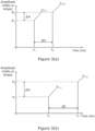
- Figure 3(a) shows the amplitudes A 1 , A 2 of the first and second fault current signals I f11, , I f1,2 when the fault distance d f1 from the first monitoring location is 100km
- Figure 3(b) shows the amplitudes A 1 , A 2 of the first and second fault current signals I f1,1 , I f1,2 when the fault distance d f1 from the first monitoring location is 200km.
- a difference in amplitude ⁇ A between the amplitudes A 1 , A 2 of the first and second fault current signals In,i, I f1,2 is greater for a fault F that is located further away from the first monitoring location 20 (i.e. in Figure 3(b) ) than that for a fault F that is located nearer the first monitoring location 20 (i.e. in Figure 3(a) ).
- the second embodiment further includes the step of calculating a value of Y ⁇ Z ⁇ at each of the first and second frequencies.
- the value of Y ⁇ Z ⁇ may instead be measured, for example during commissioning of the power transmission medium 12.
- the fault distance d f1 is compared with a predetermined set of amplitude ratios A 2 A 1 and corresponding fault locations d f1 .
- the fault distance d f1 is calculated directly from equation 2 as set out above.
- both a time interval ⁇ t 1 and amplitude ratio A 2 A 1 at the first monitoring location 20 are obtained such that respective fault distances from the first monitoring location 20 are derived.
- two fault distances are derived; one which is derived from the time interval ⁇ t 1 and one which is derived from the amplitude ratio A 2 A 1 .
- Both of the fault distances if different from one another, can be investigated by a maintenance operator to, e.g. fix the fault. Alternatively, an average of the two fault distances can be calculated.
- the third embodiment of the invention differs from the first embodiment of the invention in that the step of monitoring, at the first monitoring location 20, includes monitoring a current and a voltage of the power transmission medium 12 at a plurality of frequencies, i.e. it monitors two electrical characteristics.
- the first set of propagating fault signals includes: a first propagating fault signal of each of the current and voltage at the first frequency of the plurality of frequencies, and a second propagating fault signal of each of the current I and voltage at the second frequency of the plurality of frequencies, wherein each propagating fault signal is caused by the fault F in the power transmission medium 12.
- the first set of propagating fault signals includes two first propagating fault signals and two second propagating fault signals.
- the two first propagating fault signals in this embodiment are a first fault current signal (which is detected at the first frequency) and a first fault voltage signal (which is detected at the first frequency), while the two second propagating fault signals are a second fault current signal (which is detected at the second frequency) and a second fault voltage signal (which is detected at the second frequency).
- the time of arrival of each of the first and second fault current signals is measured and then compared to obtain a first time interval at the first monitoring location 20.
- the time of arrival of each of the first and second fault voltage signals is also measured and then compared to obtain a second time interval at the first monitoring location 20. As such, two first set comparison values are obtained.
- the method of the third embodiment derives, from each of the first and second time intervals at the first monitoring location 20, first and second fault distances from the first monitoring location 20.
- the third embodiment of the invention further includes the step of calculating an average of the first and second fault distances to obtain an average fault distance from the first monitoring location 20. The average fault distance is then used to determine a location of the fault F in the power transmission medium 12.
- each of the first and second fault distances from the first monitoring location 20 could be investigated by a maintenance operative.
- a single fault distance from the first monitoring location 20 may instead be derived by choosing one of the first and second time intervals at the first monitoring location 20 to use in the subsequent step of determining a fault location.
- the comparison values in the third embodiment may instead be amplitude ratios, as described above in relation to the second embodiment of the invention.
- the comparison values may instead be a mixture of both a time interval and an amplitude ratio at the first monitoring location 20.
- the fourth embodiment differs from the third embodiment in that it includes the step of calculating an average of the first and second time intervals at the first monitoring location 20 to obtain an average time interval, i.e. an average comparison value.
- the average time interval is then used in the fourth embodiment of the invention to derive a fault distance from the first monitoring location 20 so as to determine a location of the fault F in the power transmission medium 12.
- comparison values in the fourth embodiment may instead be amplitude ratios such that an average amplitude ratio is calculated.
- a fifth embodiment of the invention is now described which shares features of the first embodiment of the invention as described hereinabove and as shown in Figure 1 .
- the fifth embodiment of the invention differs from the first embodiment in that the first set of propagating fault signals additionally includes: a further propagating fault signal of the current at another frequency of the plurality of frequencies, wherein the or each further propagating fault signal is caused by the fault F in the power transmission medium 12.
- first, second and third fault current signals are detected at respective first, second and third frequencies.
- the fifth embodiment of the invention also includes the step of comparing the first, second and third fault current signals with one another to obtain more than one first set comparison value.
- an arrival time of each of the first, second and third fault current signals is measured which provides first, second and third arrival times. Then, the first and second arrival times are compared, i.e. subtracted, so as to obtain a first time interval. The second and third arrival times are compared so as to obtain a second time interval, and the first and third arrival times are compared so as to obtain a third time interval. In this way, each of the arrival times of the first, second and third fault current signals is compared with each of the other arrival times of the first, second and third fault current signals.
- the aforementioned step therefore obtains three first set comparison values at the first monitoring location 20.
- Only the first and second arrival times, and the second and third arrival times may instead be compared so as to obtain only first and second time intervals, i.e. two first set comparison values.
- each of the first, second and third time intervals is used to derive respective fault distances from the first monitoring location.
- a first fault distance is derived from the first time interval
- a second fault distance is derived from the second time interval
- a third fault distance is derived from the third time interval.
- Each of the first, second and third time intervals is then used to derive a respective first, second and third fault distance from the first monitoring location 20.
- a look-up table is used to compare each time interval with the values in the look-up table so as to determine respective first, second and third fault distances from the first monitoring location 20.
- the first, second and third frequencies may be 100 Hz, 500 Hz and 10 kHz such that a first time interval is obtained between 100 and 500 Hz.
- a column in the look-up table will correspond to distances for time intervals obtained between 100 and 500 Hz, and so this column would be used to determine the corresponding first fault distance. Separate columns for time intervals obtained between 500 Hz and 10 kHz, as well as for time intervals obtained between 10 and 500 kHz, would also be used to determine corresponding second and third fault distances.
- n average of the first, second and third fault distances is then calculated to obtain an average fault distance from the first monitoring location 20, and thus a location of the fault in the power transmission medium 12 is determined by the average fault distance.
- one of the first, second and third time intervals could be chosen to derive a single fault distance from the first monitoring location 20.
- first set comparison values in the method according to the fifth embodiment of the invention could instead be amplitude ratios (i.e. as described in relation to the second embodiment of the invention).
- a fault locator apparatus which carries out the method according to a sixth embodiment of the invention is designated generally by the reference numeral 100 and is shown in Figure 4 .
- the fault locator apparatus 100 includes identical features of the fault locator apparatus 10 shown in Figure 1 and like features share the same reference numerals.
- the fault locator apparatus 100 of Figure 4 differs from the fault locator apparatus 10 of Figure 1 in that it additionally includes a second fault location device 118 at a second monitoring location 120.
- the second monitoring location 120 is positioned towards the second terminal 16 opposite the first terminal 14.
- the second monitoring location 120 may instead be positioned anywhere along the power transmission medium 12.
- the method according to the sixth embodiment of the invention includes all the steps according to the first embodiment of the invention.
- the method of the sixth embodiment of the invention additionally includes the steps of:
- the electrical characteristic being monitored at the second monitoring location is also the current I, such that the second set of propagating fault signals includes a first fault current signal I f2,1 at the first frequency and a second fault current signal I f2,2 at the second frequency.
- the electrical characteristic being monitored at the second monitoring location 120 may instead be a voltage.
- the arrival time t 1 , t 2 of each of the first and second fault current signals I f2,1 , I f2,2 is detected at the second monitoring location 120.
- the first and second arrival times at the second monitoring location 120 are then compared, i.e. subtracted, to obtain a second set comparison value in the form of a time interval ⁇ t 2 at the second monitoring location 120.
- the time interval ⁇ t 2 at the second monitoring location 120 is then used to derive a fault distance d f2 from the second monitoring location 120.
- two fault distances are derived: a fault distance d f1 from the first monitoring location 20 and a fault distance d f2 from the second monitoring location 120.
- Each of the aforementioned fault distances d f1 , d f2 can be investigated by a maintenance operative.
- the method according to the sixth embodiment of the invention could include the step of monitoring first and second electrical characteristics at the second monitoring location 120 (i.e. as described in the third embodiment in relation to the first monitoring location).
- the second set comparison values in the method according to the sixth embodiment of the invention could instead be amplitude ratios at the second monitoring location 120 (i.e. as described in the second embodiment of the invention in relation to the first monitoring location).
- the seventh embodiment of the invention differs from the sixth embodiment in that it includes the step of comparing, i.e. subtracting, the first arrival time at the first monitoring location 20 with the first arrival time at the second monitoring location 120 to obtain a first combined time interval, i.e. a first combined set comparison value.
- the second arrival time at the first monitoring location 20 is compared with the second arrival time at the second monitoring location 120 to obtain a second combined time interval, i.e. a second combined set comparison value.
- the first and second combined time intervals are obtained in replacement of the first and second time intervals at the first and second monitoring locations 20, 120, i.e. so that the method includes obtaining first and second combined time intervals only.
- the first and second combined time intervals may be obtained in addition to the first and second time intervals at the first monitoring 20 location but in replacement of obtaining first and second time intervals at the second monitoring location 120, i.e. so that the method includes obtaining first and second time intervals at the first monitoring location 20 and first and second combined time intervals.
- the first and second combined time intervals may instead be obtained in addition to obtaining the first and second time intervals at both of the first and second monitoring locations 20, 120, i.e. so that the method includes obtaining first and second time intervals at the first monitoring location 20, first and second time intervals at the second monitoring location 120, and first and second combined time intervals.
- the method according to the seventh embodiment of the invention also includes the step of deriving, from each of the first and second combined time intervals, respective fault distances. This is carried out through use of a look-up table which includes separate columns relating to the different frequencies at which the measurements are being taken. For example, the arrival time t 1 at the first monitoring location 20 of the first fault current signal Ifi.i is subtracted from the arrival time at the second monitoring location 120 of the first fault current signal I f1,1 . Such subtraction creates a fault distance which is related to the centre of the cable since the subtraction would equal zero if the fault occurs in the centre of the power transmission medium 12. This value can then be related to a distance on the look-up table relative to one of the first and second monitoring locations 20, 120.
- both of the first and second monitoring locations 20, 120 are time synchronised using, e.g. GPS.
- the method according to the seventh embodiment of the invention could include the step of monitoring first and second electrical characteristics at the second monitoring location 120 (i.e. as described in the third embodiment in relation to the first monitoring location).
- the second set comparison values in the method according to the seventh embodiment of the invention could instead be amplitude ratios at the second monitoring location 120 (i.e. as described in the second embodiment of the invention in relation to the first monitoring location).
Landscapes
- Physics & Mathematics (AREA)
- General Physics & Mathematics (AREA)
- Engineering & Computer Science (AREA)
- Mathematical Physics (AREA)
- Theoretical Computer Science (AREA)
- Locating Faults (AREA)
Claims (15)
- Procédé de localisation d'une défaillance dans un support de transmission de puissance (12), le procédé comprenant les étapes consistant à :a) surveiller, à un premier emplacement de surveillance (20), une caractéristique électrique d'un support de transmission de puissance (12) à une pluralité de fréquences ;b) détecter, au premier emplacement de surveillance (20), un premier ensemble de signaux de défaillance se propageant, le premier ensemble de signaux de défaillance se propageant incluant : un premier signal de défaillance se propageant (If1,1) de la caractéristique électrique à une première fréquence de la pluralité de fréquences, et un second signal de défaillance se propageant (If1,2) de la caractéristique électrique à une seconde fréquence de la pluralité de fréquences, chaque signal de défaillance se propageant étant provoqué par la défaillance dans le support de transmission de puissance (12) ;c) comparer les premier et second signaux de défaillance se propageant (If1,1, If1,2) du premier ensemble de signaux de défaillance se propageant l'un à l'autre pour obtenir une première valeur de comparaison définie ; etd) déterminer un emplacement de la défaillance dans le support de transmission de puissance (12) en déduisant, de la première valeur de comparaison définie, une distance de défaillance à partir du premier emplacement de surveillance (20), caractérisé en ce que la comparaison des premier et second signaux de défaillance se propageant (If1,1, If1,2) du premier ensemble de signaux de défaillance se propageant l'un à l'autre inclut la comparaison d'une amplitude du premier signal de défaillance se propageant (If1,1) avec une amplitude du second signal de défaillance se propageant (If2P,2) pour obtenir un rapport d'amplitude, et dans lequel la détermination d'un emplacement de la défaillance dans le support de transmission de puissance (12) inclut la déduction, à partir du rapport d'amplitude, d'une distance de défaillance (df1) à partir du premier emplacement de surveillance (20).
- Procédé selon la revendication 1, dans lequel l'étape de comparaison des premier et second signaux de défaillance se propageant du premier ensemble de signaux de défaillance se propageant l'un à l'autre inclut la comparaison d'un temps de détection du premier signal de défaillance se propageant (If1,1) avec un temps de détection du second signal de défaillance se propageant (If2,2) pour obtenir un intervalle de temps (Δt1) entre la détection du premier signal de défaillance se propageant (If1,1) et le second signal de défaillance se propageant (If2,2); et
dans lequel l'étape de détermination d'un emplacement de la défaillance dans le support de transmission de puissance (12) inclut la déduction, à partir de la base de l'intervalle de temps, d'une distance de défaillance (df1) à partir du premier emplacement de surveillance (20). - Procédé selon la revendication 1 ou 2, dans lequel l'étape de surveillance, au niveau d'un premier emplacement de surveillance (20), inclut la surveillance d'une pluralité de caractéristiques électriques du support de transmission de puissance (12) à une pluralité de fréquences ; et
dans lequel l'étape de détection, au niveau du premier emplacement de surveillance (20), d'un premier ensemble de signaux de défaillance se propageant, le premier ensemble de signaux de défaillance se propageant inclut : un premier signal de défaillance se propageant de chaque caractéristique électrique à la première fréquence de la pluralité de fréquences et un second signal de défaillance se propageant de chaque caractéristique électrique à la seconde fréquence de la pluralité de fréquences, dans lequel chaque signal se propageant étant provoqué par la défaillance dans le support de transmission de puissance (12). - Procédé selon la revendication 3, incluant l'étape consistant à :c) comparer les premier et second signaux de défaillance se propageant (If1,1, If1,2) de chacune des caractéristiques électriques l'un à l'autre pour obtenir des premières valeurs de comparaison définies respectives ;dans lequel l'étape de détermination d'un emplacement de la défaillance dans le support de transmission de puissance (12) inclut la déduction, à partir de la base de chacune des premières valeurs de comparaison définies respectives, de distances de défaillance respectives (df1) à partir du premier emplacement de surveillance (20).
- Procédé selon la revendication 4, dans lequel l'étape de détermination d'un emplacement de la défaillance dans le support de transmission de puissance (12) inclut en outre le calcul d'une moyenne de chacune des distances de défaillance respectives pour obtenir une distance moyenne de la défaillance à partir du premier emplacement de surveillance (20).
- Procédé selon la revendication 3 ou la revendication 4, incluant l'étape consistant à :c) comparer les premier et second signaux de défaillance se propageant (If1,1, If1,2) de chacune des caractéristiques électriques l'un à l'autre pour obtenir des premières valeurs de comparaison définies respectives, et calculer une moyenne de chacune des premières valeurs de comparaison définies respectives pour obtenir une première valeur de comparaison définie moyenne ;dans lequel l'étape de détermination d'un emplacement de la défaillance dans le support de transmission de puissance (12) inclut la déduction, à partir de la première valeur de comparaison définie moyenne, d'une distance de défaillance à partir du premier emplacement de surveillance (20).
- Procédé selon l'une quelconque des revendications 1 ou 2, dans lequel l'étape de détection, au niveau du premier emplacement de surveillance (20), d'un premier ensemble de signaux de défaillance se propageant, le premier ensemble de signaux de défaillance se propageant inclut en outre : un ou plusieurs signaux de défaillance se propageant supplémentaires de la caractéristique électrique à une autre fréquence respective de la pluralité de fréquences, dans lequel le ou chaque signal de défaillance se propageant supplémentaire est provoqué par la défaillance dans le support de transmission de puissance (12),
dans lequel le procédé comprend l'étape consistant à :
c) comparer le premier signal, le second signal et le ou chaque signal de défaillance se propageant supplémentaire les uns aux autres pour obtenir plus qu'une seule première valeur de comparaison définie. - Procédé selon la revendication 7, dans lequel l'étape de comparaison du premier signal, du second signal et du ou de chaque signal de défaillance de propagation supplémentaire (If1,1, If1,2) les uns aux autres inclut la comparaison de chacun des premier, second et du ou de chaque autre signal de défaillance de propagation supplémentaire avec chacun des autres premier, second et du ou de chaque signal de défaillance de propagation supplémentaire.
- Procédé selon la revendication 7 ou la revendication 8, dans lequel l'étape de détermination d'un emplacement de la défaillance dans le support de transmission de puissance (12) inclut la déduction, à partir de chacune des premières valeurs de comparaison définies, de distances de défaillance respectives à partir du premier emplacement de surveillance (20).
- Procédé selon la revendication 9, dans lequel l'étape de détermination d'un emplacement de la défaillance dans le support de transmission de puissance (12) inclut en outre le calcul d'une moyenne de chacune des distances de défaillance respectives pour obtenir une distance de défaillance moyenne à partir du premier emplacement de surveillance (20).
- Procédé selon l'une quelconque des revendications 3 à 6, dans lequel l'étape de détection, au niveau du premier emplacement de surveillance (20), d'un premier ensemble de signaux de défaillance se propageant, le premier ensemble de signaux de défaillance se propageant inclut en outre : un ou plusieurs signaux de défaillance se propageant supplémentaires de chaque caractéristique électrique à une autre fréquence respective de la pluralité de fréquences, dans lequel chaque signal de défaillance se propageant supplémentaire est provoqué par la défaillance dans le support de transmission de puissance (20),
dans lequel le procédé inclut l'étape consistant à :
c) comparer les premier, second et le ou chaque signal de défaillance se propageant supplémentaire de chaque caractéristique électrique les uns aux autres pour obtenir plus qu'une première valeur de comparaison définie. - Procédé selon une quelconque revendication précédente, incluant en outre lese) surveiller, au niveau d'un second emplacement de surveillance (120), une caractéristique électrique du support de transmission de puissance (12) à une pluralité de fréquences ;f) détecter, au niveau du second emplacement de surveillance (120), un second ensemble de signaux de défaillance de propagation, le second ensemble de signaux de défaillance de propagation incluant : un premier signal de défaillance se propageant de la caractéristique électrique à la première fréquence, et un second signal de défaillance se propageant de la caractéristique électrique à la seconde fréquence, dans lequel chaque signal de défaillance se propageant est provoqué par la défaillance dans le support de transmission de puissance (12) ;g) comparer les premier et second signaux de défaillance se propageant du second ensemble de signaux de défaillance se propageant l'un à l'autre pour obtenir une second valeur de comparaison définie ; eth) déterminer un emplacement de la défaillance dans le support de transmission de puissance (12) en déduisant, de la seconde valeur de comparaison définie, une distance de défaillance par rapport au niveau du second emplacement de surveillance (120).
- Appareil localisateur de défaillance (10) comprenant :
un premier dispositif de localisation de défaillance (18) pour surveiller, au niveau d'un premier emplacement de surveillance (20), une caractéristique électrique d'un support de transmission de puissance (12) à une pluralité de fréquences, le premier dispositif de localisation de défaillance (18) étant configuré pour détecter, au niveau du premier emplacement de surveillance (20), un premier ensemble de signaux de défaillance de propagation, le premier ensemble de signaux de défaillance de propagation incluant : un premier signal de défaillance se propageant (If1,1) de la caractéristique électrique à une première fréquence de la pluralité de fréquences, et un second signal de défaillance se propageant (If1,2) de la caractéristique électrique à une seconde fréquence de la pluralité de fréquences, dans lequel chaque signal de défaillance se propageant est provoqué par une défaillance dans le support de transmission de puissance (12), le premier dispositif de localisation de défaillance étant en outre configuré pour comparer les premier et second signaux de défaillance se propageant du premier ensemble de signaux de défaillance se propageant l'un à l'autre pour obtenir une première valeur de comparaison définie, le premier dispositif de localisation de défaillance (18) étant en outre encore configuré pour déterminer un emplacement de la défaillance dans le support de transmission de puissance (12) en déduisant, de la première valeur de comparaison définie, une distance de défaillance à partir du premier emplacement de surveillance (20), caractérisé en ce que le premier dispositif de localisation de défaillance est configuré pour comparer les premier et second signaux de défaillance se propageant (If1,1,If1,2) du premier ensemble de signaux de défaillance se propageant l'un à l'autre en comparant en outre une amplitude du premier signal de défaillance se propageant (If1,1) avec une amplitude du second signal de défaillance se propageant (lf2P, 2) pour obtenir un rapport d'amplitude, et dans lequel le premier dispositif de localisation de défaillance est configuré pour inclure la détermination d'un emplacement de la défaillance dans le support de transmission de puissance (12) en déduisant, du rapport d'amplitude, une distance de défaillance (df1) à partir du premier emplacement de surveillance (20). - Appareil localisateur de défaillance selon la revendication 14, dans lequel le premier dispositif de localisation de défaillance est configuré pour comparer les premier et second signaux de défaillance se propageant du premier ensemble de signaux de défaillance se propageant l'un à l'autre en comparant en outre un temps de détection du premier signal de défaillance se propageant (If1,1) avec un temps de détection du second signal de défaillance se propageant (If2,2) pour obtenir un intervalle de temps (Δt1) entre la détection du premier signal de défaillance se propageant (If1,1) et le second signal de défaillance se propageant (If2,2) ; et dans lequel le premier dispositif de localisation de défaillance est configuré pour inclure la détermination d'un emplacement de la défaillance dans le support de transmission de puissance (12) en déduisant, de l'intervalle de temps, une distance de défaillance (df1) à partir du premier emplacement de surveillance (20).
- Appareil localisateur de défaillance selon la revendication 14 ou 15, comprenant en outre :
un second dispositif de localisation de défaillance (118) pour surveiller, au niveau d'un second emplacement de surveillance (120), une caractéristique électrique du support de transmission de puissance (12) à une pluralité de fréquences, le second dispositif de localisation de défaillance (118) étant configuré pour détecter, au niveau du second emplacement de surveillance (120), un second ensemble de signaux de défaillance de propagation, le second ensemble de signaux de défaillance de propagation incluant : un premier signal de défaillance se propageant de la caractéristique électrique à la première fréquence, et un second signal de défaillance se propageant de la caractéristique électrique à la seconde fréquence, dans lequel chaque signal de défaillance se propageant est provoqué par la défaillance dans le support de transmission de puissance (12), le second dispositif de localisation de défaillance (118) étant en outre configuré pour comparer les premier et second signaux de défaillance se propageant du second ensemble de signaux de défaillance se propageant l'un à l'autre pour obtenir une second valeur de comparaison définie, le second dispositif de localisation de défaillance (118) étant en outre configuré pour déterminer un emplacement de la défaillance dans le support de transmission de puissance en déduisant, de la second valeur de comparaison définie, une distance de défaillance à partir du second emplacement de surveillance (120).
Applications Claiming Priority (2)
| Application Number | Priority Date | Filing Date | Title |
|---|---|---|---|
| GB1522251.6A GB2545646B (en) | 2015-12-17 | 2015-12-17 | A method of locating a fault in a power transmission medium |
| PCT/EP2016/080030 WO2017102488A1 (fr) | 2015-12-17 | 2016-12-07 | Procédé de localisation d'une défaillance dans un milieu de transmission d'énergie |
Publications (2)
| Publication Number | Publication Date |
|---|---|
| EP3391064A1 EP3391064A1 (fr) | 2018-10-24 |
| EP3391064B1 true EP3391064B1 (fr) | 2024-02-14 |
Family
ID=55311110
Family Applications (1)
| Application Number | Title | Priority Date | Filing Date |
|---|---|---|---|
| EP16812702.5A Active EP3391064B1 (fr) | 2015-12-17 | 2016-12-07 | Procédé de localisation d'une défaillance dans un milieu de transmission d'énergie |
Country Status (5)
| Country | Link |
|---|---|
| US (1) | US11041898B2 (fr) |
| EP (1) | EP3391064B1 (fr) |
| CN (1) | CN108369254B (fr) |
| GB (1) | GB2545646B (fr) |
| WO (1) | WO2017102488A1 (fr) |
Families Citing this family (3)
| Publication number | Priority date | Publication date | Assignee | Title |
|---|---|---|---|---|
| WO2018007857A1 (fr) | 2016-07-08 | 2018-01-11 | Abb Schweiz Ag | Procédé et système de localisation d'un défaut dans un câble mixte de transport d'énergie |
| WO2018122627A1 (fr) * | 2016-12-28 | 2018-07-05 | Abb Schweiz Ag | Procédé fondé sur des ondes progressives permettant la localisation d'une défaillance dans une ligne de transmission et dispositif associé |
| US12506358B2 (en) * | 2023-05-19 | 2025-12-23 | Sense Labs, Inc. | Power event identification with distributed computing |
Citations (1)
| Publication number | Priority date | Publication date | Assignee | Title |
|---|---|---|---|---|
| US2315450A (en) * | 1941-06-14 | 1943-03-30 | Bell Telephone Labor Inc | Method of and apparatus for locating transmission faults |
Family Cites Families (9)
| Publication number | Priority date | Publication date | Assignee | Title |
|---|---|---|---|---|
| IN157698B (fr) * | 1981-04-03 | 1986-05-17 | Gen Electric | |
| DE3812432A1 (de) * | 1988-04-14 | 1989-10-26 | Siemens Ag | Verfahren und vorrichtung zur bestimmung des fehlerortes auf einer elektrischen leitung |
| IT1393308B1 (it) * | 2009-03-27 | 2012-04-20 | Techimp Technologies S A Ora Techimp Technologies S R L | Dispositivo e procedimento per localizzare scariche parziali. |
| US8547105B2 (en) * | 2009-09-30 | 2013-10-01 | Korea Electric Power Corporation | System and method for detecting a location of fault in a cable |
| CN102087332B (zh) * | 2010-12-20 | 2012-10-31 | 中国南方电网有限责任公司超高压输电公司检修试验中心 | 一种基于波速寻优的直流行波故障测距方法 |
| GB201120477D0 (en) * | 2011-11-28 | 2012-01-11 | Univ Nottingham | Fault location in power distribution systems |
| CN103344884B (zh) * | 2013-07-11 | 2016-03-23 | 杜海滨 | 电力架空线路故障双频信号检测定位方法及其专用定位仪 |
| CN203561722U (zh) * | 2013-07-11 | 2014-04-23 | 杜海滨 | 电力架空线路故障双频信号检测定位仪 |
| CN104597376B (zh) * | 2015-01-07 | 2018-08-03 | 西安理工大学 | 一种考虑实测波速的高压直流输电线路故障测距方法 |
-
2015
- 2015-12-17 GB GB1522251.6A patent/GB2545646B/en not_active Expired - Fee Related
-
2016
- 2016-12-07 WO PCT/EP2016/080030 patent/WO2017102488A1/fr not_active Ceased
- 2016-12-07 CN CN201680074283.1A patent/CN108369254B/zh active Active
- 2016-12-07 EP EP16812702.5A patent/EP3391064B1/fr active Active
- 2016-12-07 US US16/062,874 patent/US11041898B2/en active Active
Patent Citations (1)
| Publication number | Priority date | Publication date | Assignee | Title |
|---|---|---|---|---|
| US2315450A (en) * | 1941-06-14 | 1943-03-30 | Bell Telephone Labor Inc | Method of and apparatus for locating transmission faults |
Also Published As
| Publication number | Publication date |
|---|---|
| CN108369254A (zh) | 2018-08-03 |
| GB2545646A (en) | 2017-06-28 |
| WO2017102488A1 (fr) | 2017-06-22 |
| CN108369254B (zh) | 2022-03-29 |
| US11041898B2 (en) | 2021-06-22 |
| GB2545646B (en) | 2019-05-15 |
| US20180372789A1 (en) | 2018-12-27 |
| EP3391064A1 (fr) | 2018-10-24 |
| GB201522251D0 (en) | 2016-02-03 |
Similar Documents
| Publication | Publication Date | Title |
|---|---|---|
| US10746779B2 (en) | Fault location detection and distance protection apparatus and associated method | |
| US10976357B2 (en) | Method and device for determining a fault location of a ground fault relating to a line of a three-phase electrical energy supply network having a neutral point without low-resistance grounding | |
| US10598717B2 (en) | Method, device and system for determining the fault location of a fault on a line of an electrical energy supply network | |
| US6822457B2 (en) | Method of precisely determining the location of a fault on an electrical transmission system | |
| CN102159956B (zh) | 飞行器布线的电弧故障位点检测 | |
| US10228408B2 (en) | Method, device and system for determining the fault location of a fault on a line of an electrical energy supply network | |
| US10725085B2 (en) | Method, device and system for determining the fault position of a fault on a line of an electrical power supply network | |
| JP4323418B2 (ja) | ガス絶縁機器の異常状態診断方法およびシステム | |
| EP2437075B1 (fr) | Localisation des de décharges partielles dans des câbles d'énergie | |
| EP3482472B1 (fr) | Procédé et système de localisation d'un défaut dans un câble mixte de transport d'énergie | |
| KR101531641B1 (ko) | 전력케이블 부분방전 측정장치 및 이를 이용한 측정방법 | |
| JP6296689B2 (ja) | 電力ケーブルの無停電絶縁劣化診断方法 | |
| EP3391064B1 (fr) | Procédé de localisation d'une défaillance dans un milieu de transmission d'énergie | |
| CN116754890A (zh) | 一种电缆故障在线定位系统及其定位方法 | |
| EP3563163B1 (fr) | Procédé fondé sur des ondes progressives permettant la localisation d'une défaillance dans une ligne de transmission et dispositif associé | |
| US9651974B2 (en) | Electrical power transmission line length measurement and average temperature estimation | |
| CN106646149B (zh) | 一种气体绝缘全封闭组合电器的闪络故障定位系统和方法 | |
| KR101743534B1 (ko) | 반사파 계측 시스템의 케이블 전기적 상태 감시 장치 및 방법 | |
| JPH0862277A (ja) | 送電線故障点標定装置 | |
| JP2001116714A (ja) | 塗覆装された埋設金属導体の損傷判定装置及び損傷判定方法 | |
| JP2011252779A (ja) | 磁界プローブを用いた電気機器の部分放電検出方法 | |
| Miyazaki et al. | Development of partial discharge automated locating system for power cable | |
| JP4867932B2 (ja) | 埋設管損傷監視方法および埋設管損傷監視装置 | |
| HK1169172A (en) | Locating partial discharge in a power cable |
Legal Events
| Date | Code | Title | Description |
|---|---|---|---|
| STAA | Information on the status of an ep patent application or granted ep patent |
Free format text: STATUS: UNKNOWN |
|
| STAA | Information on the status of an ep patent application or granted ep patent |
Free format text: STATUS: THE INTERNATIONAL PUBLICATION HAS BEEN MADE |
|
| PUAI | Public reference made under article 153(3) epc to a published international application that has entered the european phase |
Free format text: ORIGINAL CODE: 0009012 |
|
| STAA | Information on the status of an ep patent application or granted ep patent |
Free format text: STATUS: REQUEST FOR EXAMINATION WAS MADE |
|
| 17P | Request for examination filed |
Effective date: 20180717 |
|
| AK | Designated contracting states |
Kind code of ref document: A1 Designated state(s): AL AT BE BG CH CY CZ DE DK EE ES FI FR GB GR HR HU IE IS IT LI LT LU LV MC MK MT NL NO PL PT RO RS SE SI SK SM TR |
|
| AX | Request for extension of the european patent |
Extension state: BA ME |
|
| DAV | Request for validation of the european patent (deleted) | ||
| DAX | Request for extension of the european patent (deleted) | ||
| STAA | Information on the status of an ep patent application or granted ep patent |
Free format text: STATUS: EXAMINATION IS IN PROGRESS |
|
| 17Q | First examination report despatched |
Effective date: 20211223 |
|
| P01 | Opt-out of the competence of the unified patent court (upc) registered |
Effective date: 20230522 |
|
| GRAP | Despatch of communication of intention to grant a patent |
Free format text: ORIGINAL CODE: EPIDOSNIGR1 |
|
| STAA | Information on the status of an ep patent application or granted ep patent |
Free format text: STATUS: GRANT OF PATENT IS INTENDED |
|
| INTG | Intention to grant announced |
Effective date: 20230907 |
|
| GRAS | Grant fee paid |
Free format text: ORIGINAL CODE: EPIDOSNIGR3 |
|
| GRAA | (expected) grant |
Free format text: ORIGINAL CODE: 0009210 |
|
| STAA | Information on the status of an ep patent application or granted ep patent |
Free format text: STATUS: THE PATENT HAS BEEN GRANTED |
|
| AK | Designated contracting states |
Kind code of ref document: B1 Designated state(s): AL AT BE BG CH CY CZ DE DK EE ES FI FR GB GR HR HU IE IS IT LI LT LU LV MC MK MT NL NO PL PT RO RS SE SI SK SM TR |
|
| REG | Reference to a national code |
Ref country code: GB Ref legal event code: FG4D |
|
| REG | Reference to a national code |
Ref country code: CH Ref legal event code: EP |
|
| REG | Reference to a national code |
Ref country code: DE Ref legal event code: R096 Ref document number: 602016085797 Country of ref document: DE |
|
| REG | Reference to a national code |
Ref country code: IE Ref legal event code: FG4D |
|
| REG | Reference to a national code |
Ref country code: SE Ref legal event code: TRGR |
|
| REG | Reference to a national code |
Ref country code: LT Ref legal event code: MG9D |
|
| REG | Reference to a national code |
Ref country code: NL Ref legal event code: MP Effective date: 20240214 |
|
| PG25 | Lapsed in a contracting state [announced via postgrant information from national office to epo] |
Ref country code: IS Free format text: LAPSE BECAUSE OF FAILURE TO SUBMIT A TRANSLATION OF THE DESCRIPTION OR TO PAY THE FEE WITHIN THE PRESCRIBED TIME-LIMIT Effective date: 20240614 |
|
| PG25 | Lapsed in a contracting state [announced via postgrant information from national office to epo] |
Ref country code: LT Free format text: LAPSE BECAUSE OF FAILURE TO SUBMIT A TRANSLATION OF THE DESCRIPTION OR TO PAY THE FEE WITHIN THE PRESCRIBED TIME-LIMIT Effective date: 20240214 |
|
| PG25 | Lapsed in a contracting state [announced via postgrant information from national office to epo] |
Ref country code: GR Free format text: LAPSE BECAUSE OF FAILURE TO SUBMIT A TRANSLATION OF THE DESCRIPTION OR TO PAY THE FEE WITHIN THE PRESCRIBED TIME-LIMIT Effective date: 20240515 |
|
| REG | Reference to a national code |
Ref country code: AT Ref legal event code: MK05 Ref document number: 1657458 Country of ref document: AT Kind code of ref document: T Effective date: 20240214 |
|
| PG25 | Lapsed in a contracting state [announced via postgrant information from national office to epo] |
Ref country code: RS Free format text: LAPSE BECAUSE OF FAILURE TO SUBMIT A TRANSLATION OF THE DESCRIPTION OR TO PAY THE FEE WITHIN THE PRESCRIBED TIME-LIMIT Effective date: 20240514 Ref country code: HR Free format text: LAPSE BECAUSE OF FAILURE TO SUBMIT A TRANSLATION OF THE DESCRIPTION OR TO PAY THE FEE WITHIN THE PRESCRIBED TIME-LIMIT Effective date: 20240214 Ref country code: NL Free format text: LAPSE BECAUSE OF FAILURE TO SUBMIT A TRANSLATION OF THE DESCRIPTION OR TO PAY THE FEE WITHIN THE PRESCRIBED TIME-LIMIT Effective date: 20240214 |
|
| PG25 | Lapsed in a contracting state [announced via postgrant information from national office to epo] |
Ref country code: ES Free format text: LAPSE BECAUSE OF FAILURE TO SUBMIT A TRANSLATION OF THE DESCRIPTION OR TO PAY THE FEE WITHIN THE PRESCRIBED TIME-LIMIT Effective date: 20240214 |
|
| PG25 | Lapsed in a contracting state [announced via postgrant information from national office to epo] |
Ref country code: AT Free format text: LAPSE BECAUSE OF FAILURE TO SUBMIT A TRANSLATION OF THE DESCRIPTION OR TO PAY THE FEE WITHIN THE PRESCRIBED TIME-LIMIT Effective date: 20240214 |
|
| PG25 | Lapsed in a contracting state [announced via postgrant information from national office to epo] |
Ref country code: RS Free format text: LAPSE BECAUSE OF FAILURE TO SUBMIT A TRANSLATION OF THE DESCRIPTION OR TO PAY THE FEE WITHIN THE PRESCRIBED TIME-LIMIT Effective date: 20240514 Ref country code: NO Free format text: LAPSE BECAUSE OF FAILURE TO SUBMIT A TRANSLATION OF THE DESCRIPTION OR TO PAY THE FEE WITHIN THE PRESCRIBED TIME-LIMIT Effective date: 20240514 Ref country code: NL Free format text: LAPSE BECAUSE OF FAILURE TO SUBMIT A TRANSLATION OF THE DESCRIPTION OR TO PAY THE FEE WITHIN THE PRESCRIBED TIME-LIMIT Effective date: 20240214 Ref country code: LT Free format text: LAPSE BECAUSE OF FAILURE TO SUBMIT A TRANSLATION OF THE DESCRIPTION OR TO PAY THE FEE WITHIN THE PRESCRIBED TIME-LIMIT Effective date: 20240214 Ref country code: IS Free format text: LAPSE BECAUSE OF FAILURE TO SUBMIT A TRANSLATION OF THE DESCRIPTION OR TO PAY THE FEE WITHIN THE PRESCRIBED TIME-LIMIT Effective date: 20240614 Ref country code: HR Free format text: LAPSE BECAUSE OF FAILURE TO SUBMIT A TRANSLATION OF THE DESCRIPTION OR TO PAY THE FEE WITHIN THE PRESCRIBED TIME-LIMIT Effective date: 20240214 Ref country code: GR Free format text: LAPSE BECAUSE OF FAILURE TO SUBMIT A TRANSLATION OF THE DESCRIPTION OR TO PAY THE FEE WITHIN THE PRESCRIBED TIME-LIMIT Effective date: 20240515 Ref country code: FI Free format text: LAPSE BECAUSE OF FAILURE TO SUBMIT A TRANSLATION OF THE DESCRIPTION OR TO PAY THE FEE WITHIN THE PRESCRIBED TIME-LIMIT Effective date: 20240214 Ref country code: ES Free format text: LAPSE BECAUSE OF FAILURE TO SUBMIT A TRANSLATION OF THE DESCRIPTION OR TO PAY THE FEE WITHIN THE PRESCRIBED TIME-LIMIT Effective date: 20240214 Ref country code: BG Free format text: LAPSE BECAUSE OF FAILURE TO SUBMIT A TRANSLATION OF THE DESCRIPTION OR TO PAY THE FEE WITHIN THE PRESCRIBED TIME-LIMIT Effective date: 20240214 Ref country code: AT Free format text: LAPSE BECAUSE OF FAILURE TO SUBMIT A TRANSLATION OF THE DESCRIPTION OR TO PAY THE FEE WITHIN THE PRESCRIBED TIME-LIMIT Effective date: 20240214 |
|
| PG25 | Lapsed in a contracting state [announced via postgrant information from national office to epo] |
Ref country code: PT Free format text: LAPSE BECAUSE OF FAILURE TO SUBMIT A TRANSLATION OF THE DESCRIPTION OR TO PAY THE FEE WITHIN THE PRESCRIBED TIME-LIMIT Effective date: 20240614 Ref country code: PL Free format text: LAPSE BECAUSE OF FAILURE TO SUBMIT A TRANSLATION OF THE DESCRIPTION OR TO PAY THE FEE WITHIN THE PRESCRIBED TIME-LIMIT Effective date: 20240214 |
|
| PG25 | Lapsed in a contracting state [announced via postgrant information from national office to epo] |
Ref country code: PT Free format text: LAPSE BECAUSE OF FAILURE TO SUBMIT A TRANSLATION OF THE DESCRIPTION OR TO PAY THE FEE WITHIN THE PRESCRIBED TIME-LIMIT Effective date: 20240614 Ref country code: PL Free format text: LAPSE BECAUSE OF FAILURE TO SUBMIT A TRANSLATION OF THE DESCRIPTION OR TO PAY THE FEE WITHIN THE PRESCRIBED TIME-LIMIT Effective date: 20240214 Ref country code: LV Free format text: LAPSE BECAUSE OF FAILURE TO SUBMIT A TRANSLATION OF THE DESCRIPTION OR TO PAY THE FEE WITHIN THE PRESCRIBED TIME-LIMIT Effective date: 20240214 |
|
| PG25 | Lapsed in a contracting state [announced via postgrant information from national office to epo] |
Ref country code: DK Free format text: LAPSE BECAUSE OF FAILURE TO SUBMIT A TRANSLATION OF THE DESCRIPTION OR TO PAY THE FEE WITHIN THE PRESCRIBED TIME-LIMIT Effective date: 20240214 |
|
| PG25 | Lapsed in a contracting state [announced via postgrant information from national office to epo] |
Ref country code: SM Free format text: LAPSE BECAUSE OF FAILURE TO SUBMIT A TRANSLATION OF THE DESCRIPTION OR TO PAY THE FEE WITHIN THE PRESCRIBED TIME-LIMIT Effective date: 20240214 |
|
| PG25 | Lapsed in a contracting state [announced via postgrant information from national office to epo] |
Ref country code: CZ Free format text: LAPSE BECAUSE OF FAILURE TO SUBMIT A TRANSLATION OF THE DESCRIPTION OR TO PAY THE FEE WITHIN THE PRESCRIBED TIME-LIMIT Effective date: 20240214 Ref country code: EE Free format text: LAPSE BECAUSE OF FAILURE TO SUBMIT A TRANSLATION OF THE DESCRIPTION OR TO PAY THE FEE WITHIN THE PRESCRIBED TIME-LIMIT Effective date: 20240214 |
|
| PG25 | Lapsed in a contracting state [announced via postgrant information from national office to epo] |
Ref country code: SK Free format text: LAPSE BECAUSE OF FAILURE TO SUBMIT A TRANSLATION OF THE DESCRIPTION OR TO PAY THE FEE WITHIN THE PRESCRIBED TIME-LIMIT Effective date: 20240214 |
|
| PG25 | Lapsed in a contracting state [announced via postgrant information from national office to epo] |
Ref country code: SM Free format text: LAPSE BECAUSE OF FAILURE TO SUBMIT A TRANSLATION OF THE DESCRIPTION OR TO PAY THE FEE WITHIN THE PRESCRIBED TIME-LIMIT Effective date: 20240214 Ref country code: SK Free format text: LAPSE BECAUSE OF FAILURE TO SUBMIT A TRANSLATION OF THE DESCRIPTION OR TO PAY THE FEE WITHIN THE PRESCRIBED TIME-LIMIT Effective date: 20240214 Ref country code: RO Free format text: LAPSE BECAUSE OF FAILURE TO SUBMIT A TRANSLATION OF THE DESCRIPTION OR TO PAY THE FEE WITHIN THE PRESCRIBED TIME-LIMIT Effective date: 20240214 Ref country code: EE Free format text: LAPSE BECAUSE OF FAILURE TO SUBMIT A TRANSLATION OF THE DESCRIPTION OR TO PAY THE FEE WITHIN THE PRESCRIBED TIME-LIMIT Effective date: 20240214 Ref country code: DK Free format text: LAPSE BECAUSE OF FAILURE TO SUBMIT A TRANSLATION OF THE DESCRIPTION OR TO PAY THE FEE WITHIN THE PRESCRIBED TIME-LIMIT Effective date: 20240214 Ref country code: CZ Free format text: LAPSE BECAUSE OF FAILURE TO SUBMIT A TRANSLATION OF THE DESCRIPTION OR TO PAY THE FEE WITHIN THE PRESCRIBED TIME-LIMIT Effective date: 20240214 |
|
| REG | Reference to a national code |
Ref country code: DE Ref legal event code: R097 Ref document number: 602016085797 Country of ref document: DE |
|
| PLBE | No opposition filed within time limit |
Free format text: ORIGINAL CODE: 0009261 |
|
| STAA | Information on the status of an ep patent application or granted ep patent |
Free format text: STATUS: NO OPPOSITION FILED WITHIN TIME LIMIT |
|
| 26N | No opposition filed |
Effective date: 20241115 |
|
| PG25 | Lapsed in a contracting state [announced via postgrant information from national office to epo] |
Ref country code: SI Free format text: LAPSE BECAUSE OF FAILURE TO SUBMIT A TRANSLATION OF THE DESCRIPTION OR TO PAY THE FEE WITHIN THE PRESCRIBED TIME-LIMIT Effective date: 20240214 |
|
| PG25 | Lapsed in a contracting state [announced via postgrant information from national office to epo] |
Ref country code: MC Free format text: LAPSE BECAUSE OF FAILURE TO SUBMIT A TRANSLATION OF THE DESCRIPTION OR TO PAY THE FEE WITHIN THE PRESCRIBED TIME-LIMIT Effective date: 20240214 |
|
| REG | Reference to a national code |
Ref country code: CH Ref legal event code: PL |
|
| PG25 | Lapsed in a contracting state [announced via postgrant information from national office to epo] |
Ref country code: LU Free format text: LAPSE BECAUSE OF NON-PAYMENT OF DUE FEES Effective date: 20241207 |
|
| REG | Reference to a national code |
Ref country code: BE Ref legal event code: MM Effective date: 20241231 |
|
| PG25 | Lapsed in a contracting state [announced via postgrant information from national office to epo] |
Ref country code: BE Free format text: LAPSE BECAUSE OF NON-PAYMENT OF DUE FEES Effective date: 20241231 |
|
| PG25 | Lapsed in a contracting state [announced via postgrant information from national office to epo] |
Ref country code: CH Free format text: LAPSE BECAUSE OF NON-PAYMENT OF DUE FEES Effective date: 20241231 |
|
| PG25 | Lapsed in a contracting state [announced via postgrant information from national office to epo] |
Ref country code: IE Free format text: LAPSE BECAUSE OF NON-PAYMENT OF DUE FEES Effective date: 20241207 |
|
| PGFP | Annual fee paid to national office [announced via postgrant information from national office to epo] |
Ref country code: DE Payment date: 20251126 Year of fee payment: 10 |
|
| PGFP | Annual fee paid to national office [announced via postgrant information from national office to epo] |
Ref country code: GB Payment date: 20251119 Year of fee payment: 10 |
|
| PGFP | Annual fee paid to national office [announced via postgrant information from national office to epo] |
Ref country code: IT Payment date: 20251119 Year of fee payment: 10 |
|
| PGFP | Annual fee paid to national office [announced via postgrant information from national office to epo] |
Ref country code: FR Payment date: 20251120 Year of fee payment: 10 |
|
| PGFP | Annual fee paid to national office [announced via postgrant information from national office to epo] |
Ref country code: SE Payment date: 20251119 Year of fee payment: 10 |
|
| PG25 | Lapsed in a contracting state [announced via postgrant information from national office to epo] |
Ref country code: CY Free format text: LAPSE BECAUSE OF FAILURE TO SUBMIT A TRANSLATION OF THE DESCRIPTION OR TO PAY THE FEE WITHIN THE PRESCRIBED TIME-LIMIT; INVALID AB INITIO Effective date: 20161207 |