EP3391802A1 - Sonde endoscopique - Google Patents
Sonde endoscopique Download PDFInfo
- Publication number
- EP3391802A1 EP3391802A1 EP18167322.9A EP18167322A EP3391802A1 EP 3391802 A1 EP3391802 A1 EP 3391802A1 EP 18167322 A EP18167322 A EP 18167322A EP 3391802 A1 EP3391802 A1 EP 3391802A1
- Authority
- EP
- European Patent Office
- Prior art keywords
- axis
- shaft
- handle
- endoscopic probe
- range
- Prior art date
- Legal status (The legal status is an assumption and is not a legal conclusion. Google has not performed a legal analysis and makes no representation as to the accuracy of the status listed.)
- Withdrawn
Links
Images
Classifications
-
- A—HUMAN NECESSITIES
- A61—MEDICAL OR VETERINARY SCIENCE; HYGIENE
- A61B—DIAGNOSIS; SURGERY; IDENTIFICATION
- A61B1/00—Instruments for performing medical examinations of the interior of cavities or tubes of the body by visual or photographical inspection, e.g. endoscopes; Illuminating arrangements therefor
- A61B1/00064—Constructional details of the endoscope body
- A61B1/00066—Proximal part of endoscope body, e.g. handles
-
- A—HUMAN NECESSITIES
- A61—MEDICAL OR VETERINARY SCIENCE; HYGIENE
- A61B—DIAGNOSIS; SURGERY; IDENTIFICATION
- A61B1/00—Instruments for performing medical examinations of the interior of cavities or tubes of the body by visual or photographical inspection, e.g. endoscopes; Illuminating arrangements therefor
- A61B1/04—Instruments for performing medical examinations of the interior of cavities or tubes of the body by visual or photographical inspection, e.g. endoscopes; Illuminating arrangements therefor combined with photographic or television appliances
- A61B1/042—Instruments for performing medical examinations of the interior of cavities or tubes of the body by visual or photographical inspection, e.g. endoscopes; Illuminating arrangements therefor combined with photographic or television appliances characterised by a proximal camera, e.g. a CCD camera
-
- A—HUMAN NECESSITIES
- A61—MEDICAL OR VETERINARY SCIENCE; HYGIENE
- A61B—DIAGNOSIS; SURGERY; IDENTIFICATION
- A61B1/00—Instruments for performing medical examinations of the interior of cavities or tubes of the body by visual or photographical inspection, e.g. endoscopes; Illuminating arrangements therefor
- A61B1/00002—Operational features of endoscopes
- A61B1/00011—Operational features of endoscopes characterised by signal transmission
- A61B1/00016—Operational features of endoscopes characterised by signal transmission using wireless means
-
- A—HUMAN NECESSITIES
- A61—MEDICAL OR VETERINARY SCIENCE; HYGIENE
- A61B—DIAGNOSIS; SURGERY; IDENTIFICATION
- A61B1/00—Instruments for performing medical examinations of the interior of cavities or tubes of the body by visual or photographical inspection, e.g. endoscopes; Illuminating arrangements therefor
- A61B1/00002—Operational features of endoscopes
- A61B1/00039—Operational features of endoscopes provided with input arrangements for the user
-
- A—HUMAN NECESSITIES
- A61—MEDICAL OR VETERINARY SCIENCE; HYGIENE
- A61B—DIAGNOSIS; SURGERY; IDENTIFICATION
- A61B1/00—Instruments for performing medical examinations of the interior of cavities or tubes of the body by visual or photographical inspection, e.g. endoscopes; Illuminating arrangements therefor
- A61B1/00002—Operational features of endoscopes
- A61B1/00043—Operational features of endoscopes provided with output arrangements
- A61B1/00045—Display arrangement
- A61B1/0005—Display arrangement combining images e.g. side-by-side, superimposed or tiled
-
- A—HUMAN NECESSITIES
- A61—MEDICAL OR VETERINARY SCIENCE; HYGIENE
- A61B—DIAGNOSIS; SURGERY; IDENTIFICATION
- A61B1/00—Instruments for performing medical examinations of the interior of cavities or tubes of the body by visual or photographical inspection, e.g. endoscopes; Illuminating arrangements therefor
- A61B1/00112—Connection or coupling means
- A61B1/00114—Electrical cables in or with an endoscope
-
- A—HUMAN NECESSITIES
- A61—MEDICAL OR VETERINARY SCIENCE; HYGIENE
- A61B—DIAGNOSIS; SURGERY; IDENTIFICATION
- A61B1/00—Instruments for performing medical examinations of the interior of cavities or tubes of the body by visual or photographical inspection, e.g. endoscopes; Illuminating arrangements therefor
- A61B1/06—Instruments for performing medical examinations of the interior of cavities or tubes of the body by visual or photographical inspection, e.g. endoscopes; Illuminating arrangements therefor with illuminating arrangements
- A61B1/07—Instruments for performing medical examinations of the interior of cavities or tubes of the body by visual or photographical inspection, e.g. endoscopes; Illuminating arrangements therefor with illuminating arrangements using light-conductive means, e.g. optical fibres
-
- A—HUMAN NECESSITIES
- A61—MEDICAL OR VETERINARY SCIENCE; HYGIENE
- A61B—DIAGNOSIS; SURGERY; IDENTIFICATION
- A61B34/00—Computer-aided surgery; Manipulators or robots specially adapted for use in surgery
- A61B34/20—Surgical navigation systems; Devices for tracking or guiding surgical instruments, e.g. for frameless stereotaxis
-
- A—HUMAN NECESSITIES
- A61—MEDICAL OR VETERINARY SCIENCE; HYGIENE
- A61B—DIAGNOSIS; SURGERY; IDENTIFICATION
- A61B90/00—Instruments, implements or accessories specially adapted for surgery or diagnosis and not covered by any of the groups A61B1/00 - A61B50/00, e.g. for luxation treatment or for protecting wound edges
- A61B90/20—Surgical microscopes characterised by non-optical aspects
-
- A—HUMAN NECESSITIES
- A61—MEDICAL OR VETERINARY SCIENCE; HYGIENE
- A61B—DIAGNOSIS; SURGERY; IDENTIFICATION
- A61B90/00—Instruments, implements or accessories specially adapted for surgery or diagnosis and not covered by any of the groups A61B1/00 - A61B50/00, e.g. for luxation treatment or for protecting wound edges
- A61B90/36—Image-producing devices or illumination devices not otherwise provided for
-
- A—HUMAN NECESSITIES
- A61—MEDICAL OR VETERINARY SCIENCE; HYGIENE
- A61B—DIAGNOSIS; SURGERY; IDENTIFICATION
- A61B90/00—Instruments, implements or accessories specially adapted for surgery or diagnosis and not covered by any of the groups A61B1/00 - A61B50/00, e.g. for luxation treatment or for protecting wound edges
- A61B90/36—Image-producing devices or illumination devices not otherwise provided for
- A61B90/361—Image-producing devices, e.g. surgical cameras
-
- A—HUMAN NECESSITIES
- A61—MEDICAL OR VETERINARY SCIENCE; HYGIENE
- A61B—DIAGNOSIS; SURGERY; IDENTIFICATION
- A61B1/00—Instruments for performing medical examinations of the interior of cavities or tubes of the body by visual or photographical inspection, e.g. endoscopes; Illuminating arrangements therefor
- A61B1/00112—Connection or coupling means
-
- A—HUMAN NECESSITIES
- A61—MEDICAL OR VETERINARY SCIENCE; HYGIENE
- A61B—DIAGNOSIS; SURGERY; IDENTIFICATION
- A61B90/00—Instruments, implements or accessories specially adapted for surgery or diagnosis and not covered by any of the groups A61B1/00 - A61B50/00, e.g. for luxation treatment or for protecting wound edges
- A61B90/36—Image-producing devices or illumination devices not otherwise provided for
- A61B90/37—Surgical systems with images on a monitor during operation
- A61B2090/373—Surgical systems with images on a monitor during operation using light, e.g. by using optical scanners
-
- A—HUMAN NECESSITIES
- A61—MEDICAL OR VETERINARY SCIENCE; HYGIENE
- A61B—DIAGNOSIS; SURGERY; IDENTIFICATION
- A61B90/00—Instruments, implements or accessories specially adapted for surgery or diagnosis and not covered by any of the groups A61B1/00 - A61B50/00, e.g. for luxation treatment or for protecting wound edges
- A61B90/39—Markers, e.g. radio-opaque or breast lesions markers
- A61B2090/3983—Reference marker arrangements for use with image guided surgery
Definitions
- the present invention relates to an endoscopic probe having a shaft and a handle which includes a front end, a rear end, and a handle portion extending between the rear end and the rear end.
- microsurgery such as in neurosurgery, for example, after removing a deep-seated tumor or treating an aneurysm, there is a regular need to look at locations that are out of line of sight of a surgical microscope.
- endoscopic probes are used, as they are for example in DE 10 2015 004 546 A1 .
- US 7,162,292 B2 and in US 2011/0178395 A1 are described.
- Endoscopic probes typically have a handle, from one end of which extends a shaft and from the other end a cable goes off.
- One challenge is to design the endoscopic probe in such a way that, on the one hand, it has a high degree of ergonomics and, on the other hand, a collision of the endoscopic probe with a surgical microscope used together with it can be reliably avoided.
- Object of the present invention is to provide an endoscopic probe available, which has a high ergonomics and with a Reliably avoid collision with a surgical microscope used with it.
- An endoscopic probe comprises a handle having a front end, a rear end having a trailing end axis, and a straight handle portion extending between the front end and the trailing end having a handle portion axis.
- it comprises a shaft extending from the front end of the handle with a shaft axis and, when the rear end is formed as a cable outlet end, a cable exiting from the rear end.
- the axes are each given by the connecting line between the centers of the cross sections at the ends of the respective section or the shaft.
- the shaft axis, the rear end axis and the handle portion axis lie within a plane.
- the shaft axis encloses an angle in the range of 100 to 140 degrees, in particular in the range of 110 to 130 degrees, and preferably in the range of 115 to 125 degrees, with the handle portion axis.
- the handle portion axis subtends an angle in the range of 110 to 130 degrees, particularly in the range of 115 to 125 degrees, with the trailing end axis, and the shaft axis subtends an angle in the range of 30 to 90 degrees with the trailing end axis.
- the angle which the shaft axis encloses with the grip portion axis may in particular have the same magnitude as the angle which the grip portion axis encloses with the rear end axis.
- the cable exits the rear end at an angle of no more than 20 degrees maximum, preferably no more than 10 feet to the trailing end axis.
- the cable can emerge parallel to the rear end axis from the rear end.
- the tail may include an antenna and / or an accumulator.
- the rear end may contain an antenna and / or an accumulator.
- the bending of the endoscopic probe according to the invention according to the specified angles makes it possible to keep the overall length in the direction of the handle portion axis low and to minimize the risk of collision of the handle or the rear end or cable outlet with a surgical microscope used at the same time, while a high degree of ergonomics is achieved , While an angle between the shaft axis and the 90 degree handgrip axis would be optimal for minimizing the risk of collision, it has been found that such an angle does not provide good handleability in the predominantly one-handed use of the endoscopic probe. In particular, the rotation in the situs and the safe insertion of the probe are affected by an angle of 90 degrees.
- the inventive angle between the shaft axis and the handle axis i.
- the handle portion axis in the range of 100 to 140 degrees, in particular in the range of 110 to 130 degrees, and preferably in the range of 115 to 125 degrees allows uncomplicated turning of the shaft in the situs and safe insertion into the situs without the risk of collision with significantly increase the simultaneously used surgical microscope.
- the cable can be removed via the back of the hand by the selected angle of the rear end axis, so that it does not unnecessarily hinder the user when turning the probe in the situs.
- the indicated angles therefore characterize a particularly advantageous geometry of the endoscopic probe.
- the shaft may have a length in the range from 50 to 180 mm, in particular from 90 to 130 mm. On the one hand, this is long enough to be used in microsurgical To be used interventions and on the other hand short enough so that a collision of the handle with the surgical microscope when handling the endoscopic probe can be avoided.
- the shaft may have a wall thickness in the range from 0.3 to 0.5 mm, in particular in the range from 0.35 to 0.45 mm, at least in a distal section. At an adjoining the front end of the handle proximal portion of the shaft, this may have an increased wall thickness in the range of 1.3 to 1.5 mm, in particular in the range of 1.35 to 1.45 mm.
- the proximal portion may have a length in the range of 10 to 20 mm, in particular in the range of 13 to 17 mm.
- a shaft with the dimensions mentioned is on the one hand small enough to get along with the least possible surgical intervention and on the other hand stable enough to avoid damaging the shaft during surgery.
- the clear shaft diameter is large enough to allow high image quality and high resolution of images taken by the shaft.
- an image-guiding optics may then be present in the interior of the shaft, with which object light emanating from an object observed by means of the endoscopic probe is guided to an image sensor arranged in the handle, which is preferably an HD sensor.
- enough space remains in the shaft for illuminating light, which is emitted by a light source arranged inside the handle and used to illuminate the object observed by means of the endoscopic probe, to be guided to the observed object with the aid of a light guide guided through the interior of the shaft can.
- the handle of the endoscopic probe according to the invention may have a diameter of 18 to 38 mm, in particular from 24 to 32 mm.
- the handle portion and the front end together have a length in the range of 100 to 120 mm, in particular in the range of 105 to 115 mm.
- the handle portion of the handle in a plane perpendicular to the common plane of the shaft axis, the Griffabitessachse and the trailing end axis has a cross-section, which is an intersection of an imaginary extension of the shaft axis with an imaginary extension of the rear end axis facing cross-sectional top and has a cross-sectional lower side facing away from this point of intersection.
- the cross-sectional upper side has a central, preferably arched portion and two adjoining the central portion less convex or concave or straight portions which form sections of the legs of an imaginary isosceles triangle, the apex is centrally above the cross-sectional top.
- the isosceles triangle may in particular be an equilateral triangle.
- This embodiment of the grip portion of the endoscopic probe is based on the finding that the grip portion is usually not covered with the entire hand, but is often taken for better fine motor handling similar to the bow of a violin with the fingertips, or in the crook between the thumb and index finger is lying on the middle finger balanced and guided with the tips of the thumb and forefinger.
- the straight sections of the cross-sectional upper side thereby form advantageous gripping surfaces for gripping the grip section with the tip of the thumb on one side and the fingertips of, as a rule, at least the one Forefinger and possibly the middle finger on the other side.
- the endoscopic probe With the help of the straight sections, which serve as gripping surfaces or gripping structures in the grip section, safe handling and ergonomic guidance of the endoscopic probe can be ensured. Due to the symmetry in the shape of an isosceles triangle, the endoscopic probe is suitable for safe handling with the left hand as well as safe handling with the right hand.
- the cross-sectional lower side of the cross-section of the handle portion may have a curvature, the cross-sectional lower side then comprising a central region with a central curvature and sections adjoining the central region with a smaller curvature compared to the central curvature.
- the sections with the convex or concave curvature which is smaller in comparison with the central curvature, can also be free of a curvature and / or run parallel to one another.
- the cross-sectional underside may also have a support surface for the middle finger. This can be realized for example in the form of a flat portion of the cross-sectional underside or in the form of a recess or depression in the cross-sectional underside.
- the shaft when the shaft is arranged at the front end of the handle, that the front end has a maximum projection over the shaft, which is dimensioned perpendicular to the direction of extension of the shaft axis that the angle ⁇ between an imaginary line extending from the distal end of the shaft and extending in the plane of the shaft axis, the rear end axis and the handle portion axis and tangent to the front end of the handle is not more than 8 Degree, preferably not more than 5 degrees.
- the axis of the front end of the handle does not coincide with the shaft axis, but that the two axes have an angle to each other, which is chosen such that at the distal end of the shaft, the supernatant of the front end is balanced, so that the angle ⁇ can be further reduced and in particular can be zero degrees.
- the shaft and the handle including the connection between the shaft and the handle, may be liquid and gas tight, and the shaft and the handle may be made of an autoclavable material.
- the shaft and the handle can be sterilized in an autoclave.
- This embodiment is particularly suitable for wireless endoscopic probes.
- endoscopic probes with cable the cable and the connection between the cable and the handle are liquid and gas tight, and the cable is made of an autoclavable material.
- endoscopic probe can be sterilized with cable in an autoclave. The sterilization eliminates the need to use a drape, so that the ergonomic handling is maintained in any case.
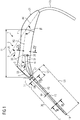
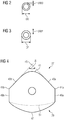
- FIG. 1 a representation of the endoscopic probe with a handle and a shaft and the FIGS. 2 to 4 Cross sections through the shaft or the handle.
- the endoscopic probe in the present embodiment comprises a handle 1 with a handle portion 3, a front end 5 and a rear end 21.
- the handle portion 3 extends along a Griffablvesachse AG, the handle portion axis, the centers of the two end surfaces 9, 11 of the handle portion 3 interconnected.
- a front end 5 connects, from which extends the shaft 15 along a shaft axis AS.
- the straight shaft 15 in the present exemplary embodiment has a proximal end 17 adjoining the front end 5 of the handle 1 and a distal end 19 remote from the front end 5 of the handle 1.
- His shank axis AS includes in the present embodiment with the handle portion axis AG an angle ⁇ of 130 degrees.
- this angle ⁇ need not necessarily be 130 degrees, but may be in a range of 100 to 140 degrees, more preferably in a range of 110 to 130 degrees, and preferably in a range of 115 to 125 degrees , This area, and in particular the narrower of the two areas, has proven to be ergonomically advantageous.
- the rear end 21 of the handle 1 connects, from the present in the present Embodiment, a cable 23 exits the handle 1.
- the rear end 21 has a rear end axis AK, wherein the rear end axis AK extends through the center of the adjoining the end surface 11 of the handle portion cross-sectional area and through the center of the exit surface of the cable 23.
- the cable 23 preferably exits in a direction from the rear end 21 which corresponds to the direction of the trailing end axis AK. In principle, however, it can also emerge at a small angle to the rear end axis AK, the small angle having no more than a maximum of 20 degrees, preferably not more than 10 degrees.
- the rear end axis AK closes in the present embodiment with the handle portion axis AG be an angle ⁇ of 130 degrees. It should be noted at this point, however, that the angle ⁇ in other embodiments may be in the range between 110 and 130 degrees, preferably in the range between 115 and 125 degrees. The range of 110 to 130 degrees, and in particular the range of 115 to 125 degrees, has proven to be ergonomically advantageous.
- the shank axis AS, the handle portion axis AG and the rear end axis AK lie in a common plane, whereby imaginary extensions of the shank axis AS and the rear end axis AK intersect at an intersection 25.
- the imaginary extensions of the two axles are in Fig. 1 dashed lines. They include an angle ⁇ of 80 degrees in the present embodiment. Again, however, that the angle ⁇ need not necessarily be 80 degrees, but may be in a range between 30 and 90 degrees, for example, 60 degrees.
- the mentioned ranges for the angle ⁇ result from the previously stated angular ranges for the angles ⁇ and ⁇ .
- the endoscopic probe can be designed so that it can be performed equally advantageous both with the left hand and with the right hand.
- the handle portion 3 together with the front end 5 has a length LH of 110 mm. However, it is also possible to deviate from this value. Possible lengths of the handle portion 3 including the front end 5 may be in the range between 100 and 120 mm.
- the shaft 15 has in the present embodiment from the proximal end 17 to the distal end 19 has a length LS of 120 mm. Again, it should be noted that in other embodiments of the endoscopic probe, the shaft length LS may have a different value in a range of 50 to 180 mm, in particular in the range of 90 to 130 mm.
- the outer diameter DD of the shank (see also FIG. 2 making a cut along the line II-II FIG. 1 1) is 3.6 mm in a distal portion 26 of the shaft 15, and the wall thickness DWD in the distal portion 26 is 0.4 mm.
- the outer diameter DD and the wall thickness DWD in the distal portion 26 of the shaft 15 can also assume other values, the values for the outer diameter DD ranging between 3.0 and 4.1, in particular in the range of 3 , 4 to 3.8 mm, and the values for the wall thickness DWD are in the range between 0.4 and 0.5 mm, in particular in the range of 0.35 to 0.45 mm.
- proximal portion 27 in a located between the distal portion 26 and the proximal end 17 of the shaft 15 proximal portion 27 (see also FIG. 3 making a cut along the line III-III FIG.
- the shaft has an increased wall thickness DWP, which in the present embodiment is 1.4 mm and in other embodiments of the endoscopic probe according to the invention in the range of 1.3 to 1.5 mm, in particular in the range of 1.35 to 1 , 45 mm, can lie.
- the outer diameter DP of the shaft 15 in the proximal portion 27 is correspondingly increased.
- the proximal section extends over a length LP of 15 mm, but in other embodiments it can also assume other values in the range between 10 and 20 mm, in particular in the range from 13 to 17, mm.
- the mentioned diameters and wall thicknesses of the shank 15 are selected such that on the one hand they enable the shank to be inserted into narrow operation channels, but on the other hand the shank has sufficient stability that it is not damaged during handling.
- the inner diameter of the shaft is large enough to be able to pass on the one hand an optical fiber 31, with the light of a light source 29 arranged in the handle 1 can be passed to the distal end 19 of the shaft 15, and on the other hand reflected from the observed by the endoscopic probe observation object Light via an image-guiding optics, which is designed in the present case as an ordered fiber bundle 33, to a digital image sensor 35, such as a CCD sensor or a CMOS sensor, can be passed.
- the optics in the form of lens combinations.
- the dimensions of the shank allow it to accommodate an image-guiding optic which enables recording of HD videos by means of the digital image sensor 35. It is also possible to arrange the digital image sensor 35 at or in the distal tip of the shaft 15.
- the handle portion 3 of the handle 1 has a special cross-section.
- This cross section is in FIG. 4 shown a section along the line IV-IV in FIG. 1 shows.
- the cross section lies in a plane which is perpendicular to the common plane of the shaft axis AS, the handle portion axis AG and the rear end axis AK.
- the in FIG. 4 shown cross-section has a cross-sectional upper side 37 and a cross-sectional lower side 39.
- the cross-sectional upper side 37 forms in the grip section 3 that side of the grip section on which the point of intersection 25 lies between the imaginary extensions of the shaft axis AS and the rear end axis AK.
- the cross-sectional upper side 37 has a curved central portion 41 and two adjoining slightly curved portions 43a, 43b in the present exemplary embodiment.
- the bulges may vary along the handle portion axis AG.
- the tangents to the slightly curved portions 43a, 43b thereby form sections of the legs of an imaginary isosceles triangle, the tip of which lies centrally above the cross-sectional top 41.
- the angle ⁇ at the tip is in the range between 45 and 75 degrees and is in the present embodiment, at least in a region of the handle portion 60 degrees.
- the surfaces of the grip portion 3 formed by the slightly curved portions 43a, 43b of the cross-sectional upper face are gripping surfaces for gripping the grip portion with the thumb on the one hand and the tip of the index finger on the other hand.
- the cross-sectional underside 39 has a central region 47 with a central curvature, on which sections 49a, 49b adjoin on both sides, which have a smaller curvature compared to the central curvature, ie a curvature with a larger curvature radius.
- the radius of curvature is very large, so that the areas 49a, 49b have no curvature.
- the regions 49a, 49b thereby run symmetrically to the axis of symmetry of the imaginary isosceles triangle of the cross-sectional upper side 37.
- relatively sharp edges 44a, 44b can be formed at the junctions of the straight sections 49a, 49b of the underside of the cross section with the straight sections 43a, 43b of the cross-sectional upper side, which can form a tactile marking and thus contribute to the safety in handling the endoscopic probe.
- a contact surface for the middle finger, resting on the middle finger can may be a portion of the grip portion 3 in which the central portion of the cross-sectional lower surface 39 has a flatter curvature, as shown in FIG FIG. 4 is indicated by the dashed line 51.
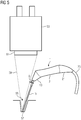
- FIG. 5 The use of an endoscopic probe according to the invention together with a surgical microscope 53 is shown in FIG FIG. 5 shown schematically.
- images from the bottom 57 of an operating channel 55 are recorded with the aid of the shaft 15 of the endoscopic probe.
- the operation channel 55 is observed during handling of the endoscopic probe with the surgical microscope 53 to monitor the movement of the shaft 15 in the operation channel 55.
- it is important that the endoscopic probe does not collide with the surgical microscope 53 during a movement within the surgical channel 55, for example during a rotation about the shaft axis AS, during insertion into the surgical channel 55 or during withdrawal from the surgical canal 55.
- Such a collision can be achieved by the described angled geometry of the shaft 15, the handle portion 3 and the rear end 21.
- the relative to the handle portion 3 angled rear end 21 makes it possible to dissipate in the present embodiment from the rear end 21 outgoing cable 23 low on the back of the hand.
- the supernatant O in the present embodiment a maximum of one tenth, in particular a maximum of one fifteenth and preferably a maximum of one twentieth the shaft length LS correspond.
- the supernatant is 5 mm with a shaft length of 120 mm, which corresponds to a twenty-fourth of the shaft length.
- the angle ⁇ is 3 degrees. As in FIG. 5 is indicated, can be achieved that the leading to the main lens 61 opening cone 51 of the observation beam path is not or at most slightly shadowed by the endoscopic probe.
- the shaft 15 and the handle 1, including the connection between the shaft 15 and handle 1 are liquid and gas tight.
- the shaft 15 and the handle 1 are made of a material that can be sterilized in an autoclave. Characterized in that the endoscopic probe is designed liquid and gas-tight, the components arranged in the interior of the handle and the shaft are protected during the treatment in an autoclave, so that they are not affected by the treatment. A drapefree working is possible through.
- the angle was ⁇ 130 degrees, the angle ⁇ 130 Grand and the angle ⁇ 80 degrees. In another embodiment, the angle ⁇ is 120 degrees, the angle ⁇ 120 Grand and the angle ⁇ 60 degrees.
- the present invention has been described in detail with reference to an embodiment for explanation purposes.
- a person skilled in the art recognizes that it is possible to deviate from this exemplary embodiment.
- Further rejections of the embodiment are possible, as has already been stated at various points in the embodiment.
- the endoscopic probe can be wireless, wherein the data transmission can then take place, for example, via WLAN, Bluetooth or infrared transmission.
- the rear end is then, for example, an antenna for wireless transmission or an accumulator, which provides the energy required for the transmission available.
- a sterilizable cable is then eliminated.
- the invention is therefore not intended to be limited to the wired embodiment, but only to an endoscopic probe as claimed in the appended claims.
Landscapes
- Health & Medical Sciences (AREA)
- Life Sciences & Earth Sciences (AREA)
- Surgery (AREA)
- Engineering & Computer Science (AREA)
- Molecular Biology (AREA)
- Public Health (AREA)
- Veterinary Medicine (AREA)
- Biomedical Technology (AREA)
- Heart & Thoracic Surgery (AREA)
- Medical Informatics (AREA)
- Nuclear Medicine, Radiotherapy & Molecular Imaging (AREA)
- Animal Behavior & Ethology (AREA)
- General Health & Medical Sciences (AREA)
- Pathology (AREA)
- Physics & Mathematics (AREA)
- Biophysics (AREA)
- Optics & Photonics (AREA)
- Radiology & Medical Imaging (AREA)
- Oral & Maxillofacial Surgery (AREA)
- Computer Networks & Wireless Communication (AREA)
- Robotics (AREA)
- Endoscopes (AREA)
- Instruments For Viewing The Inside Of Hollow Bodies (AREA)
Applications Claiming Priority (1)
| Application Number | Priority Date | Filing Date | Title |
|---|---|---|---|
| DE102017108272.7A DE102017108272A1 (de) | 2017-04-19 | 2017-04-19 | Endoskopische Sonde |
Publications (1)
| Publication Number | Publication Date |
|---|---|
| EP3391802A1 true EP3391802A1 (fr) | 2018-10-24 |
Family
ID=62002012
Family Applications (1)
| Application Number | Title | Priority Date | Filing Date |
|---|---|---|---|
| EP18167322.9A Withdrawn EP3391802A1 (fr) | 2017-04-19 | 2018-04-13 | Sonde endoscopique |
Country Status (5)
| Country | Link |
|---|---|
| US (1) | US10945587B2 (fr) |
| EP (1) | EP3391802A1 (fr) |
| JP (1) | JP2018175868A (fr) |
| CN (1) | CN108814528A (fr) |
| DE (1) | DE102017108272A1 (fr) |
Families Citing this family (2)
| Publication number | Priority date | Publication date | Assignee | Title |
|---|---|---|---|---|
| DE102019129218A1 (de) * | 2019-10-29 | 2021-04-29 | Aesculap Ag | Chirurgisches Instrumentenhandstück |
| CN117320609A (zh) * | 2021-05-20 | 2023-12-29 | 安布股份有限公司 | 具有人体工程学手柄的内窥镜 |
Citations (6)
| Publication number | Priority date | Publication date | Assignee | Title |
|---|---|---|---|---|
| US4617915A (en) * | 1984-03-27 | 1986-10-21 | Fuji Photo Optical Co., Ltd. | Construction of manual control section of endoscope |
| US6413208B1 (en) * | 1998-06-19 | 2002-07-02 | Karl Storz Gmbh & Co. Kg | Medical instrument and method for endoscopic removal of the saphenous vein |
| US20140052131A1 (en) * | 2011-05-19 | 2014-02-20 | Cimpax Aps | Electrosurgical pencil |
| EP2883504A2 (fr) * | 2013-12-13 | 2015-06-17 | Covidien LP | Ensemble de couplage permettant d'interconnecter un ensemble adaptateur et un dispositif chirurgical et systèmes chirurgicaux associés |
| US20170086651A1 (en) * | 2014-06-20 | 2017-03-30 | Olympus Corporation | Endoscope apparatus |
| EP3248533A1 (fr) * | 2015-12-17 | 2017-11-29 | Olympus Corporation | Endoscope |
Family Cites Families (26)
| Publication number | Priority date | Publication date | Assignee | Title |
|---|---|---|---|---|
| US4148550A (en) * | 1977-05-09 | 1979-04-10 | American Hospital Supply Corporation | Rod lens assembly and method of making the same |
| JPS57183822A (en) * | 1981-05-01 | 1982-11-12 | Olympus Optical Co | Endoscope |
| US5184602A (en) | 1988-11-18 | 1993-02-09 | Effner Biomet Gmbh | Endoscope, in particular an arthroscope |
| JPH0819507A (ja) * | 1994-07-07 | 1996-01-23 | Fuji Photo Optical Co Ltd | 内視鏡 |
| US7637905B2 (en) * | 2003-01-15 | 2009-12-29 | Usgi Medical, Inc. | Endoluminal tool deployment system |
| JP3729322B2 (ja) * | 2000-02-03 | 2005-12-21 | フジノン株式会社 | 内視鏡の手元操作部 |
| US7162292B2 (en) | 2001-05-21 | 2007-01-09 | Olympus Corporation | Beam scanning probe system for surgery |
| JP2003153853A (ja) | 2001-11-22 | 2003-05-27 | Olympus Optical Co Ltd | 内視鏡 |
| US20060004258A1 (en) * | 2004-07-02 | 2006-01-05 | Wei-Zen Sun | Image-type intubation-aiding device |
| BRPI0822028A2 (pt) * | 2008-01-18 | 2015-07-21 | Johnson & Johnson Ltd | Cabo ergonômico de câmera para um dispositivo endoscópico de formação de imagens |
| CA2722566A1 (fr) * | 2008-04-25 | 2009-10-29 | Downey, Earl, C. | Instrument chirurgical laparoscopique |
| DE102008029301A1 (de) * | 2008-06-19 | 2009-12-24 | Richard Wolf Gmbh | Endoskop- und Schaftsystem |
| US20110166420A1 (en) * | 2009-04-08 | 2011-07-07 | Hans-Joachim Miesner | Imaging method and apparatus |
| US20110178395A1 (en) | 2009-04-08 | 2011-07-21 | Carl Zeiss Surgical Gmbh | Imaging method and system |
| EP2430972B1 (fr) * | 2009-12-04 | 2017-11-29 | Olympus Corporation | Endoscope sans fil portatif |
| CN102711584B (zh) * | 2010-08-05 | 2015-09-02 | 奥林巴斯医疗株式会社 | 内窥镜 |
| JP6180405B2 (ja) * | 2011-05-03 | 2017-08-16 | エンドーシー コーポレイションEndosee Corporation | ヒステロスコピー及び子宮内膜生検用の方法及び装置 |
| US9107573B2 (en) * | 2012-10-17 | 2015-08-18 | Karl Storz Endovision, Inc. | Detachable shaft flexible endoscope |
| US9168099B2 (en) * | 2012-10-25 | 2015-10-27 | Gyrus Acmi, Inc. | Lithotripsy apparatus using a flexible endoscope |
| US10278729B2 (en) * | 2013-04-26 | 2019-05-07 | Medtronic Xomed, Inc. | Medical device and its construction |
| JP5881908B1 (ja) * | 2014-03-18 | 2016-03-09 | オリンパス株式会社 | 内視鏡 |
| DE102015004546B4 (de) | 2015-04-08 | 2023-05-04 | Schölly Fiberoptic GmbH | Medizinisches Instrument |
| CN108024695B (zh) * | 2015-08-11 | 2021-05-04 | 特里斯医疗有限公司 | 完全集成的一次性组织可视化装置 |
| DE102015113424A1 (de) * | 2015-08-14 | 2017-02-16 | Invendo Medical Gmbh | Handgriff eines Endoskops |
| JP6455954B2 (ja) * | 2016-10-05 | 2019-01-23 | オリンパス株式会社 | 挿入機器 |
| US11419614B2 (en) * | 2017-01-11 | 2022-08-23 | Carevature Medical Ltd. | Surgical instrument with bended shaft |
-
2017
- 2017-04-19 DE DE102017108272.7A patent/DE102017108272A1/de active Pending
-
2018
- 2018-04-11 US US15/950,715 patent/US10945587B2/en active Active
- 2018-04-12 JP JP2018076547A patent/JP2018175868A/ja not_active Withdrawn
- 2018-04-13 EP EP18167322.9A patent/EP3391802A1/fr not_active Withdrawn
- 2018-04-19 CN CN201810353996.2A patent/CN108814528A/zh active Pending
Patent Citations (6)
| Publication number | Priority date | Publication date | Assignee | Title |
|---|---|---|---|---|
| US4617915A (en) * | 1984-03-27 | 1986-10-21 | Fuji Photo Optical Co., Ltd. | Construction of manual control section of endoscope |
| US6413208B1 (en) * | 1998-06-19 | 2002-07-02 | Karl Storz Gmbh & Co. Kg | Medical instrument and method for endoscopic removal of the saphenous vein |
| US20140052131A1 (en) * | 2011-05-19 | 2014-02-20 | Cimpax Aps | Electrosurgical pencil |
| EP2883504A2 (fr) * | 2013-12-13 | 2015-06-17 | Covidien LP | Ensemble de couplage permettant d'interconnecter un ensemble adaptateur et un dispositif chirurgical et systèmes chirurgicaux associés |
| US20170086651A1 (en) * | 2014-06-20 | 2017-03-30 | Olympus Corporation | Endoscope apparatus |
| EP3248533A1 (fr) * | 2015-12-17 | 2017-11-29 | Olympus Corporation | Endoscope |
Also Published As
| Publication number | Publication date |
|---|---|
| US10945587B2 (en) | 2021-03-16 |
| JP2018175868A (ja) | 2018-11-15 |
| US20180303318A1 (en) | 2018-10-25 |
| CN108814528A (zh) | 2018-11-16 |
| DE102017108272A1 (de) | 2018-10-25 |
Similar Documents
| Publication | Publication Date | Title |
|---|---|---|
| DE69732859T2 (de) | Chirurgisches instrument für endoskopchirurgie | |
| DE10004264C2 (de) | Vorrichtung zur intrakorporalen, minimal-invasiven Behandlung eines Patienten | |
| DE69920896T2 (de) | Medizinische vorrichtung, welche den zugang zum körper ermöglicht | |
| EP3245937B1 (fr) | Endoscope et instrument de nettoyage pour un endoscope | |
| DE19962209B4 (de) | Spitze für ein Ultraschallendoskop | |
| DE102018110620A1 (de) | Endoskopdeflecting mit distalem Abklappmechanismus | |
| DE19523959A1 (de) | Endoskop | |
| DE4133073A1 (de) | Trokar | |
| DE112016000132B4 (de) | Ultraschallendoskop | |
| EP3720333A1 (fr) | Endoscope doté d'une partie de préhension pivotante | |
| WO2010105649A1 (fr) | Queue tubulaire d'un instrument chirurgical et son utilisation | |
| EP3738558A1 (fr) | Instrument d'éclairage permettant d'éclairer l'espace intraoculaire | |
| DE102018002356A1 (de) | Instrumenten-Set und Verfahren zur Durchführung von Operationen an Wirbeln oder Knochen | |
| EP3391802A1 (fr) | Sonde endoscopique | |
| EP2380485A1 (fr) | Endoscope fixe | |
| EP0918489B1 (fr) | Gaine de trocart s'utilisant pour l'endoscopie | |
| DE202013103110U1 (de) | Medizinisches Instrument | |
| DE102012203908B3 (de) | Instrumentensystem für die minimalinvasive Chirurgie in der Single-Port-Technik | |
| DE102010013917A1 (de) | Medizinisches Instrument für einen minimalinvasiven Eingriff | |
| DE10359337B4 (de) | Endoskop | |
| DE29521451U1 (de) | Instrument zur endoskopischen Therapie | |
| DE102022113124A1 (de) | Handgriff für medizinische Endoskope und Endoskopsystem | |
| DE202019006174U1 (de) | Lichtinstrument zur Beleuchtung des intraokularen Raumes | |
| DE202011051869U1 (de) | Chirurgisches Instrument zur Durchführung eines minimal-invasiven Eingriffs | |
| DE102017113729A1 (de) | Medizinisches Instrument |
Legal Events
| Date | Code | Title | Description |
|---|---|---|---|
| PUAI | Public reference made under article 153(3) epc to a published international application that has entered the european phase |
Free format text: ORIGINAL CODE: 0009012 |
|
| STAA | Information on the status of an ep patent application or granted ep patent |
Free format text: STATUS: THE APPLICATION HAS BEEN PUBLISHED |
|
| AK | Designated contracting states |
Kind code of ref document: A1 Designated state(s): AL AT BE BG CH CY CZ DE DK EE ES FI FR GB GR HR HU IE IS IT LI LT LU LV MC MK MT NL NO PL PT RO RS SE SI SK SM TR |
|
| AX | Request for extension of the european patent |
Extension state: BA ME |
|
| STAA | Information on the status of an ep patent application or granted ep patent |
Free format text: STATUS: REQUEST FOR EXAMINATION WAS MADE |
|
| 17P | Request for examination filed |
Effective date: 20190423 |
|
| RBV | Designated contracting states (corrected) |
Designated state(s): AL AT BE BG CH CY CZ DE DK EE ES FI FR GB GR HR HU IE IS IT LI LT LU LV MC MK MT NL NO PL PT RO RS SE SI SK SM TR |
|
| GRAP | Despatch of communication of intention to grant a patent |
Free format text: ORIGINAL CODE: EPIDOSNIGR1 |
|
| STAA | Information on the status of an ep patent application or granted ep patent |
Free format text: STATUS: GRANT OF PATENT IS INTENDED |
|
| INTG | Intention to grant announced |
Effective date: 20210218 |
|
| STAA | Information on the status of an ep patent application or granted ep patent |
Free format text: STATUS: THE APPLICATION IS DEEMED TO BE WITHDRAWN |
|
| 18D | Application deemed to be withdrawn |
Effective date: 20210629 |