EP3391973A1 - Appareil d'application - Google Patents
Appareil d'application Download PDFInfo
- Publication number
- EP3391973A1 EP3391973A1 EP18170746.4A EP18170746A EP3391973A1 EP 3391973 A1 EP3391973 A1 EP 3391973A1 EP 18170746 A EP18170746 A EP 18170746A EP 3391973 A1 EP3391973 A1 EP 3391973A1
- Authority
- EP
- European Patent Office
- Prior art keywords
- coating material
- spray gun
- application apparatus
- passage
- gun
- Prior art date
- Legal status (The legal status is an assumption and is not a legal conclusion. Google has not performed a legal analysis and makes no representation as to the accuracy of the status listed.)
- Granted
Links
Images


Classifications
-
- B—PERFORMING OPERATIONS; TRANSPORTING
- B05—SPRAYING OR ATOMISING IN GENERAL; APPLYING FLUENT MATERIALS TO SURFACES, IN GENERAL
- B05B—SPRAYING APPARATUS; ATOMISING APPARATUS; NOZZLES
- B05B13/00—Machines or plants for applying liquids or other fluent materials to surfaces of objects or other work by spraying, not covered by groups B05B1/00 - B05B11/00
- B05B13/06—Machines or plants for applying liquids or other fluent materials to surfaces of objects or other work by spraying, not covered by groups B05B1/00 - B05B11/00 specially designed for treating the inside of hollow bodies
-
- B—PERFORMING OPERATIONS; TRANSPORTING
- B05—SPRAYING OR ATOMISING IN GENERAL; APPLYING FLUENT MATERIALS TO SURFACES, IN GENERAL
- B05B—SPRAYING APPARATUS; ATOMISING APPARATUS; NOZZLES
- B05B13/00—Machines or plants for applying liquids or other fluent materials to surfaces of objects or other work by spraying, not covered by groups B05B1/00 - B05B11/00
- B05B13/02—Means for supporting work; Arrangement or mounting of spray heads; Adaptation or arrangement of means for feeding work
- B05B13/04—Means for supporting work; Arrangement or mounting of spray heads; Adaptation or arrangement of means for feeding work the spray heads being moved during spraying operation
- B05B13/0405—Means for supporting work; Arrangement or mounting of spray heads; Adaptation or arrangement of means for feeding work the spray heads being moved during spraying operation with reciprocating or oscillating spray heads
- B05B13/041—Means for supporting work; Arrangement or mounting of spray heads; Adaptation or arrangement of means for feeding work the spray heads being moved during spraying operation with reciprocating or oscillating spray heads with spray heads reciprocating along a straight line
-
- B—PERFORMING OPERATIONS; TRANSPORTING
- B05—SPRAYING OR ATOMISING IN GENERAL; APPLYING FLUENT MATERIALS TO SURFACES, IN GENERAL
- B05B—SPRAYING APPARATUS; ATOMISING APPARATUS; NOZZLES
- B05B13/00—Machines or plants for applying liquids or other fluent materials to surfaces of objects or other work by spraying, not covered by groups B05B1/00 - B05B11/00
- B05B13/06—Machines or plants for applying liquids or other fluent materials to surfaces of objects or other work by spraying, not covered by groups B05B1/00 - B05B11/00 specially designed for treating the inside of hollow bodies
- B05B13/0618—Machines or plants for applying liquids or other fluent materials to surfaces of objects or other work by spraying, not covered by groups B05B1/00 - B05B11/00 specially designed for treating the inside of hollow bodies only a part of the inside of the hollow bodies being treated
-
- B—PERFORMING OPERATIONS; TRANSPORTING
- B05—SPRAYING OR ATOMISING IN GENERAL; APPLYING FLUENT MATERIALS TO SURFACES, IN GENERAL
- B05B—SPRAYING APPARATUS; ATOMISING APPARATUS; NOZZLES
- B05B13/00—Machines or plants for applying liquids or other fluent materials to surfaces of objects or other work by spraying, not covered by groups B05B1/00 - B05B11/00
- B05B13/06—Machines or plants for applying liquids or other fluent materials to surfaces of objects or other work by spraying, not covered by groups B05B1/00 - B05B11/00 specially designed for treating the inside of hollow bodies
- B05B13/0627—Arrangements of nozzles or spray heads specially adapted for treating the inside of hollow bodies
- B05B13/0636—Arrangements of nozzles or spray heads specially adapted for treating the inside of hollow bodies by means of rotatable spray heads or nozzles
-
- B—PERFORMING OPERATIONS; TRANSPORTING
- B05—SPRAYING OR ATOMISING IN GENERAL; APPLYING FLUENT MATERIALS TO SURFACES, IN GENERAL
- B05B—SPRAYING APPARATUS; ATOMISING APPARATUS; NOZZLES
- B05B13/00—Machines or plants for applying liquids or other fluent materials to surfaces of objects or other work by spraying, not covered by groups B05B1/00 - B05B11/00
- B05B13/06—Machines or plants for applying liquids or other fluent materials to surfaces of objects or other work by spraying, not covered by groups B05B1/00 - B05B11/00 specially designed for treating the inside of hollow bodies
- B05B13/069—Machines or plants for applying liquids or other fluent materials to surfaces of objects or other work by spraying, not covered by groups B05B1/00 - B05B11/00 specially designed for treating the inside of hollow bodies the hollow bodies having a closed end
-
- B—PERFORMING OPERATIONS; TRANSPORTING
- B05—SPRAYING OR ATOMISING IN GENERAL; APPLYING FLUENT MATERIALS TO SURFACES, IN GENERAL
- B05B—SPRAYING APPARATUS; ATOMISING APPARATUS; NOZZLES
- B05B14/00—Arrangements for collecting, re-using or eliminating excess spraying material
-
- B—PERFORMING OPERATIONS; TRANSPORTING
- B05—SPRAYING OR ATOMISING IN GENERAL; APPLYING FLUENT MATERIALS TO SURFACES, IN GENERAL
- B05B—SPRAYING APPARATUS; ATOMISING APPARATUS; NOZZLES
- B05B15/00—Details of spraying plant or spraying apparatus not otherwise provided for; Accessories
- B05B15/50—Arrangements for cleaning; Arrangements for preventing deposits, drying-out or blockage; Arrangements for detecting improper discharge caused by the presence of foreign matter
- B05B15/58—Arrangements for cleaning; Arrangements for preventing deposits, drying-out or blockage; Arrangements for detecting improper discharge caused by the presence of foreign matter preventing deposits, drying-out or blockage by recirculating the fluid to be sprayed from upstream of the discharge opening back to the supplying means
-
- B—PERFORMING OPERATIONS; TRANSPORTING
- B05—SPRAYING OR ATOMISING IN GENERAL; APPLYING FLUENT MATERIALS TO SURFACES, IN GENERAL
- B05B—SPRAYING APPARATUS; ATOMISING APPARATUS; NOZZLES
- B05B3/00—Spraying or sprinkling apparatus with moving outlet elements or moving deflecting elements
- B05B3/02—Spraying or sprinkling apparatus with moving outlet elements or moving deflecting elements with rotating elements
- B05B3/10—Spraying or sprinkling apparatus with moving outlet elements or moving deflecting elements with rotating elements discharging over substantially the whole periphery of the rotating member
-
- B—PERFORMING OPERATIONS; TRANSPORTING
- B05—SPRAYING OR ATOMISING IN GENERAL; APPLYING FLUENT MATERIALS TO SURFACES, IN GENERAL
- B05B—SPRAYING APPARATUS; ATOMISING APPARATUS; NOZZLES
- B05B7/00—Spraying apparatus for discharge of liquids or other fluent materials from two or more sources, e.g. of liquid and air, of powder and gas
- B05B7/02—Spray pistols; Apparatus for discharge
- B05B7/04—Spray pistols; Apparatus for discharge with arrangements for mixing liquids or other fluent materials before discharge
- B05B7/0416—Spray pistols; Apparatus for discharge with arrangements for mixing liquids or other fluent materials before discharge with arrangements for mixing one gas and one liquid
-
- B—PERFORMING OPERATIONS; TRANSPORTING
- B05—SPRAYING OR ATOMISING IN GENERAL; APPLYING FLUENT MATERIALS TO SURFACES, IN GENERAL
- B05C—APPARATUS FOR APPLYING FLUENT MATERIALS TO SURFACES, IN GENERAL
- B05C7/00—Apparatus specially designed for applying liquid or other fluent material to the inside of hollow work
- B05C7/02—Apparatus specially designed for applying liquid or other fluent material to the inside of hollow work the liquid or other fluent material being projected
-
- B—PERFORMING OPERATIONS; TRANSPORTING
- B05—SPRAYING OR ATOMISING IN GENERAL; APPLYING FLUENT MATERIALS TO SURFACES, IN GENERAL
- B05B—SPRAYING APPARATUS; ATOMISING APPARATUS; NOZZLES
- B05B13/00—Machines or plants for applying liquids or other fluent materials to surfaces of objects or other work by spraying, not covered by groups B05B1/00 - B05B11/00
- B05B13/02—Means for supporting work; Arrangement or mounting of spray heads; Adaptation or arrangement of means for feeding work
- B05B13/0278—Arrangement or mounting of spray heads
Definitions
- the present invention relates to an application apparatus that applies a coating material on an inner wall surface of a container, and more particularly to an application apparatus that applies a coating material that improves slipperiness on the inner wall surface of the container.
- plastic containers are widely used for various purposes because of good formability and low production cost.
- One problem with such plastic containers was that when the containers contain a viscous material such as mayonnaise-like food products, it is hard to use up all the contents as the material tends to stick to the inner wall surface of the container.
- coating materials that improve the ability of the contained material to slide down have been developed recently, and it has been known that with such a coating material being applied on the inner wall surface of the container, the contents in the container can easily be used up due to the improved ability to slide down the inner wall surface of the container.
- the spray gun could be inserted in the container, and a spray of coating material could be ejected while the spray gun is rotated and moved up and down or back and forth.
- the container could be rotated instead of the spray gun, and the coating material could be ejected while the spray gun is moved up and down or back and forth.
- the present invention is directed to solve these problems, and an object thereof is to provide an application apparatus capable of applying a coating material uniformly on an inner wall surface of a container with a simple structure while preventing leakage of the coating material and an increase in the installation space.
- the present invention provides an application apparatus that applies a coating material on an inner wall surface of a container, including: a spray gun having a spray nozzle and including a coating material ejection passage formed therein; an outgoing pipe and a return pipe attached to the spray gun and forming a coating material circulatory path connecting to the coating material ejection passage; a supply control unit controlling supply of the coating material from the coating material circulatory path to the coating material ejection passage; a rotary drive unit rotating the spray gun around an axis extending along a longitudinal direction of the gun; and a moving unit moving the spray gun along the longitudinal direction of the gun, wherein the outgoing pipe and the return pipe are each provided with a resilient-shape part capable of extending and contracting resiliently, whereby the problems described above are solved.
- the outgoing pipe and the return pipe attached to the spray gun are each provided with a resilient-shape part capable of extending and contracting resiliently, so that, when the spray gun is rotated, and moved up and down or back and forth, the resilient-shape part extends and prevents too much stress from being applied to a connecting part between each pipe and the spray gun, while preventing the pipes from taking up much space in the lateral direction and thus avoiding an increase in the required installation space.
- the resilient-shape part has a shape that allows it to extend and contract resiliently, even if the pipes are made from a material that has a strength high enough to withstand the pressure of the coating material flowing through the coating material circulatory path, each pipe can be imparted with the ability to extend and contract.
- the configuration in which the spray gun is rotated and not the containers obviates the need to install a container rotation device in the existing production line, as well as enables efficient application of coating material within a limited space of the production line, so that facility investment costs can be kept low.
- the resilient-shape part provided to the outgoing pipe and the return pipe is formed in a coil shape. Since the resilient-shape part can be contracted into a compact shape, it requires less installation space. Also, the cross-sectional shape of the pipe can easily be maintained constant even when the resilient-shape part undergoes resilient deformation, so that smooth flow of the coating material can be maintained.
- the rotary drive unit rotates the spray gun through a predetermined angle in forward and reverse directions. Since the degree to which each pipe winds around the spray gun can be mitigated by rotating the spray gun in various combinations of forward and reverse directions, the connecting part between each pipe and the spray gun can be prevented from being subjected to too much stress.
- the rotary drive unit rotates the spray gun 180° to 360°. Since the coating material can be applied to the entire inner wall surface of the container irrespective of the nozzle shape of the spray nozzle, the degree of design freedom of the nozzle shape is increased.
- the spray nozzle has a nozzle shape capable of ejecting the coating material such as to spread symmetrically on both right and left sides.
- the rotation angle of the spray nozzle rotated by the rotary drive unit can be set to 180°, so that the rotary drive unit can be configured simply and at low cost.
- the spray gun is disposed such that the longitudinal direction of the gun coincides with an up-and-down direction. Since the application apparatus can be readily incorporated in an existing production line that conveys containers to which coating material is to be applied in a horizontal direction, the facility investment costs can be kept low.
- the supply control unit includes an air ejecting unit that supplies air to the spray gun to allow the coating material to be supplied from the coating material circulatory path to the coating material ejection passage, and the rotary drive unit and the moving unit each include a pneumatic actuator. Since the same air supply source can be shared by using the air as the drive medium of various means, the facility investment costs can be reduced.
- a gear is interposed between a rotary actuator of the rotary drive unit and the spray gun, so that the rotation angle of the spray gun can be easily adjusted by changing the gear ratio.
- the apparatus further includes a suction mechanism that can be positioned opposite a container opening. Since the coating material that has been ejected from the spray nozzle and atomized inside the container can be sucked through the container opening, the atomized coating material is prevented from adhering to the upper end edge of the container opening, spray nozzle, or unintended places such as the outer environment, and also the coating material can be applied uniformly on the inner wall surface of the container.
- the suction mechanism is configured as an airflow augmentation unit
- the airflow augmentation unit includes an airflow augmenting passage having a gas supply part, a suction port, and an ejection port, the suction port being disposed opposite the container opening. Since the atomized coating material can be sucked out from the suction port in a favorable manner with the use of the compressed gas, the apparatus does not require bulky equipment such as a vacuum system and can be made more simple with a smaller installation space.
- the airflow augmentation unit is disposed such that a shaft of the spray gun is positioned inside the airflow augmenting passage. Since the suction port of the airflow augmentation unit can cover the entire container opening, the atomized coating material can be sucked reliably.
- the apparatus further includes second moving unit that moves the airflow augmentation unit along the longitudinal direction of the gun, so that the suction port can be brought closer to the container opening to ensure that the atomized coating material is sucked, and also the application apparatus can be readily incorporated into an existing production line.
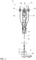
- the application apparatus 10 applies a coating material L that improves surface slipperiness for the contents of a container on an inner wall surface of the container C, which is for containing a viscous material such as mayonnaise-like food products, by ejecting the coating material L inside the container C from a spray nozzle 22 that is inserted into the container C while the spray gun 20 is rotated, as shown in Fig. 1 and Fig. 2 .
- the application apparatus 10 includes, as shown in Fig. 1 to Fig. 3 , the spray gun 20 having a coating material ejection passage 23, an outgoing pipe 30 and a return pipe 33 attached to the spray gun 20 and forming part of a coating material circulatory path 40, a supply control unit 50 that controls supply of the coating material L from the coating material circulatory path 40 to the coating material ejection passage 23, rotary drive unit 60 that rotates the spray gun 20 around an axis extending along the longitudinal direction of the gun, a moving unit 70 that move the spray gun 20 along the longitudinal direction of the gun, a rotatable support 80 having a bearing 81 that rotatably supports the spray gun 20, and a container holding unit 90 that holds the container C.
- the spray gun 20 for ejecting the coating material L includes a shaft 21 that is thin enough to be inserted into the container C, and the spray nozzle 22 provided at the tip of the shaft 21, as shown in Fig. 1 to Fig. 3 .
- the spray nozzle 22 may have any shape as long as it sprays the coating material L in a spreading manner, preferably such that the coating material L spreads symmetrically on both right and left sides.
- one spray nozzle 22 is provided at the tip of the shaft 21, but any number of spray nozzles 22 can be provided anywhere.
- the spray nozzle 22 may have an air jet orifice so as to atomize the coating material L ejected from the spray nozzle 22.
- This coating material passage 24 forms part of the coating material circulatory path 40 for circulating the coating material L, together with a coating material passage 31 inside the outgoing pipe 30 and a coating material passage 34 inside the return pipe 33.
- the outgoing pipe 30 and return pipe 33 are disposed outside the spray gun 20 as shown in Fig. 1 , and each have one end attached to the spray gun 20 and the other end attached to a tank (not shown) that stores the coating material L.
- the outgoing pipe 30 and return pipe 33 are made of a hard synthetic resin such as high-density polyethylene so as to be able to withstand the pressure of the coating material L circulating through the coating material passages 31 and 34 formed inside.
- the outgoing pipe 30 and return pipe 33 are transparent or translucent so that the state of the coating material L (settling, etc.) can be checked from outside.
- Coil-like resilient-shape parts 32 and 35 are formed to the outgoing pipe 30 and return pipe 33 as shown in Fig. 1 .
- the resilient-shape parts 32 and 35 are not specifically limited to the coil-like shape and they may have any shape as long as they include a plurality of bent or curved parts and can resiliently extend and contract.
- the supply control unit 50 includes, as can be seen from Fig. 3 , an open/close valve 51 provided between the coating material ejection passage 23 and the coating material circulatory path 40, an air supply pipe 52 that forms an air ejecting unit for supplying air to open and close this valve 51, and an air supply source (not shown) connected to the air supply pipe 52. Supplying the air through the air supply pipe 52 to the spray gun 20 opens the valve 51, so that the coating material L is supplied from the coating material circulatory path 40 to the coating material ejection passage 23, with the use of the pressure of the coating material L inside the coating material circulatory path 40. In this way, in this embodiment, the timing and amount of ejecting the coating material L from the spray nozzle 22 are controlled by adjusting the timing and duration of the air supply.
- the air supply pipe 52 should preferably have a resilient-shape part similar to the resilient-shape parts 32 and 35 of the outgoing pipe 30 and return pipe 33 described above.
- the supply control unit 50 may have any other specific forms as long as the supply of the coating material L from the coating material circulatory path 40 to the coating material ejection passage 23 is controlled.
- the drive source of the supply control unit 50 may also be any type other than the one that uses air as described above, such as an electrical drive source.
- the rotary drive unit 60 includes, as shown in Fig. 2 , a rotary actuator 61, and a first gear 62 and a second gear 63 disposed between the rotary actuator 61 and the spray gun 20.
- the first gear 62 is fixed to an output shaft of the rotary actuator 61
- the second gear 63 is fixed to the rear end of the spray gun 20, so that the rotary drive force of the rotary actuator 61 is transmitted to the spray gun 20 with a predetermined gear ratio by these first gear 62 and second gear 63.
- the rotary actuator 61 is a pneumatic rotary actuator 61 that uses air as the drive medium and connected to an air supply source (not shown) by a rotary actuator air supply pipe 64.
- the rotary actuator air supply pipe 64 should preferably have a resilient-shape part similar to the resilient-shape parts 32 and 35 of the outgoing pipe 30 and return pipe 33 described above.
- the rotary drive unit 60 may have any specific form as long as the spray gun 20 is rotated around an axis extending along the longitudinal direction of the gun, i.e., in the illustrated example, along the up-and-down direction.
- the drive source of the rotary drive unit 60 may also be any type other than the one that uses air as described above, such as an electrical drive source. While the rotary drive unit 60 in this embodiment is configured to rotate the spray gun 20 360° in forward and reverse directions, the rotation angle of the spray gun 20 rotated by the rotary drive unit 60 may be set otherwise as long as it is 180° or more.
- the spray nozzle 22 may be provided with one ejection port, and if the spray gun 20 is rotated 180° in forward and reverse directions, the spray nozzle 22 may be provided with ejection ports at two symmetrical positions.
- the moving unit 70 is configured as a pneumatic rodless cylinder as shown in Fig. 2 and include a base 71 having a linear guide 72, and a slider 73 movable along the up-and-down direction.
- An air supply source (not shown) is connected to the base 71, while the rotary actuator 61 and rotary support 80 are fixed to the slider 73.
- the moving unit 70 may have any specific form such as a rod cylinder as long as the spray gun 20 is moved along the longitudinal direction of the gun, i.e., in the illustrated example, along the up-and-down direction.
- the drive source of the moving unit 70 may also be any type other than the one that uses air as described above, such as an electrical drive source.
- the supply control unit 50, rotary drive unit 60, and moving unit 70 described above share the same air supply source (not shown) as the drive power source. Alternatively, however, separate air supply sources (not shown) may be provided for each of these units.
- the container holding unit 90 is arranged to be movable in horizontal directions, configured to hold the container C in a stationary state, and used also in other process steps of the container production line.
- the container holding unit 90 may have any specific form as long as the container C is held.
- the container C to which coating material is to be applied is moved to a position below the spray gun 20, and the spray gun 20 is lowered so as to insert the shaft 21 into the container C.
- the spray gun 20 is rotated 360°, and at the same time the coating material L is ejected from the spray nozzle 22.
- the spray gun 20 is lifted, the spray gun 20 is rotated 360° in the opposite direction from the one when the gun was lowered, and at the same time the coating material L is ejected from the spray nozzle 22.
- the lifting speed of the spray gun 20 as the spray gun 20 moves up is changed in accordance with the shape of the container C so as to apply the coating material L uniformly on the inner surface of the container C.
- the embodiment described above is one example of operation of the application apparatus 10 of the present invention. While the application apparatus 10 is oriented vertically, the application apparatus 10 may also be oriented horizontally, and as long as it is disposed along the longitudinal direction of the gun, the application apparatus 10 may be installed in any style.
- the application apparatus 10 may be operated in accordance with the shape, size and the like of the container C, with suitable settings such as the speed of the spray gun 20 as it moves down and up, the rotation speed of the spray gun 20, the rotation timing of the spray gun 20, the ejection timing of the coating material L, the rotation angle of the spray gun 20, and the ejection amount of the coating material L, etc.
- the coating material applied to the container described above is a material that improves surface slipperiness for the contents
- the container described above is a container air-tightly packed with a viscous material such as mayonnaise-like food products
- the coating material may be of any kind, and the container may be used for any purposes.
- the coating material L ejected from the spray nozzle 22 is atomized inside the container C.
- This atomized coating material L may adhere to the upper end edge of the container opening C1 and adversely affect the bonding of a sealing member to the upper end edge of the container opening C1, or, the coating material may adhere to the spray nozzle 22 and adversely affect ejection of the coating material L from the spray nozzle 22.
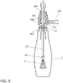
- an airflow augmentation unit 100 is provided as a suction mechanism that can be positioned opposite the container opening C1 in the longitudinal direction, in the illustrated example, above the container opening C1.
- a suction duct or the like is provided above or in the vicinity of the airflow augmentation unit 100 as a countermeasure against contamination of the outer environment.
- the airflow augmentation unit 100 is formed substantially cylindrical, and includes a gas supply part 102 connected to an air supply source (not shown) via a gas supply pipe 105, and an airflow augmenting passage 101 having a lower suction port 103 and an upper ejection port 104, as shown in Fig. 4 and Fig. 5 , and provides the function of the flow increasing mechanism such as those shown in Japanese Patent Applications Laid-open Nos. H4-184000 and 2006-291941 .
- the airflow augmentation unit 100 has the airflow augmenting passage 101 extending along the longitudinal direction of the gun, in the illustrated example, up-and-down direction, and is disposed such that the shaft 21 of the spray gun 20 is positioned inside the airflow augmenting passage 101.
- a gas such as air supplied to the gas supply part 102 is ejected along the inner circumference of the airflow augmenting passage 101 toward the ejection port 104 at high speed.
- the gas containing the coating material L that has been atomized inside the container C is sucked from the suction port 103 positioned above and opposite the container opening C1 and ejected from the ejection port 104 at high speed and high pressure.
- the suction mechanism may have other specific forms that use other principles than the one described above as long as the gas can be sucked from the container opening C1.
- the gas supplied to the gas supply part 102 may be any gas. Air is more preferable, since the suction mechanism can then share the same air supply source with other constituent elements (such as the supply control unit 50, rotary drive unit 60, moving unit 70, second moving unit 110, etc.).
- the airflow augmentation unit 100 is configured to be movable in the up-and-down direction by the second moving unit 110 as shown in Fig. 4 independently of the movement of the spray gun 20 along the longitudinal direction of the gun, in the illustrated example, up-and-down direction.
- the second moving unit 110 is configured as a pneumatic rodless cylinder, and made up of a second linear guide 111 formed on the base 71 in a lower part of the linear guide 72, and a second slider 112 that is configured to be movable along the up-and-down direction and supports the airflow augmentation unit 100.
- the second moving unit 110 may not be provided, and the airflow augmentation unit 100 may be disposed fixedly so that it does not move up and down.
- the container C to which the coating material is to be applied is moved to a position below the spray gun 20, after which the shaft 21 of the spray gun 20 is inserted into the container C.
- the airflow augmentation unit 100 is moved down, and stopped at a position where the suction port 103 of the airflow augmenting passage 101 is slightly spaced from the container opening C1.
- the distance between the suction port 103 and the container opening C1 should be as small as possible within a range in which the negative pressure created by the suction of the gas from the container C by the airflow augmentation unit 100 does not cause the container C to deform or stick to the suction port 103.
- a gas is supplied to the gas supply part 102 so that the gas inside the container C is sucked by the airflow augmentation unit 100, while the coating material L is ejected from the spray nozzle 22 and applied on the inner wall surface of the container C.
- the embodiment described above is one example of operation of the application apparatus 10 of the present invention.
- the timing of moving the airflow augmentation unit 100 to the proximity of the container opening C1, and the timing of sucking the gas from the container C, etc., may be determined suitably.
- the spray gun 20 may be moved in the horizontal direction, with its shaft 21 being positioned inside the airflow augmenting passage 101, and the airflow augmentation unit 100 may be installed in any style as long as it is disposed along the longitudinal direction.
- Aspect 1 An application apparatus that applies a coating material on an inner wall surface of a container, comprising: a spray gun having a spray nozzle and including a coating material ejection passage formed therein; an outgoing pipe and a return pipe attached to said spray gun and forming a coating material circulatory path connecting to said coating material ejection passage; a supply control unit controlling supply of the coating material from said coating material circulatory path to said coating material ejection passage; a rotary drive unit rotating said spray gun around an axis extending along a longitudinal direction of the gun; and a moving unit moving said spray gun along the longitudinal direction of the gun, wherein said outgoing pipe and said return pipe are each provided with a resilient-shape part capable of extending and contracting resiliently.
- Aspect 2 The application apparatus according to aspect 1, wherein said resilient-shape part is formed in a coil shape.
- Aspect 3 The application apparatus according to aspect 1 or 2, wherein said rotary drive unit rotates said spray gun through a predetermined angle in forward and reverse directions.
- Aspect 4 The application apparatus according to any one of aspects 1 to 3, wherein said rotary drive unit rotates said spray gun 180° to 360°.
- Aspect 5 The application apparatus according to any one of aspects 1 to 4, wherein said spray nozzle has a nozzle shape capable of ejecting the coating material such as to spread symmetrically on both right and left sides.
- Aspect 6 The application apparatus according to any one of aspects 1 to 5, wherein said spray gun is disposed such that the longitudinal direction of the gun coincides with an up-and-down direction.
- Aspect 7 The application apparatus according to any one of aspects 1 to 6, wherein said supply control unit includes an air ejecting unit that supplies air to said spray gun to allow the coating material to be supplied from said coating material circulatory path to said coating material ejection passage, and said rotary drive unit and said moving unit each include a pneumatic actuator.
- Aspect 8 The application apparatus according to any one of aspects 1 to 7, wherein said rotary drive unit includes a rotary actuator, and a gear interposed between said rotary actuator and said spray gun.
- Aspect 9 The application apparatus according to any one of aspects 1 to 8, further comprising a suction mechanism that can be positioned opposite a container opening.
- Aspect 10 The application apparatus according to aspect 9, wherein said suction mechanism includes an airflow augmentation unit, said airflow augmentation unit including an airflow augmenting passage having a gas supply part, a suction port, and an ejection port, said suction port being disposed opposite the container opening.
- Aspect 11 The application apparatus according to aspect 10, wherein said airflow augmentation unit is disposed such that a shaft of said spray gun is positioned inside said airflow augmenting passage.
- Aspect 12 The application apparatus according to aspect 10 or 11, further comprising a second moving unit that moves said airflow augmentation unit along the longitudinal direction of the gun.
Landscapes
- Nozzles (AREA)
- Spray Control Apparatus (AREA)
- Coating Apparatus (AREA)
Applications Claiming Priority (3)
| Application Number | Priority Date | Filing Date | Title |
|---|---|---|---|
| JP2014087331 | 2014-04-21 | ||
| PCT/JP2015/051518 WO2015162951A1 (fr) | 2014-04-21 | 2015-01-21 | Dispositif d'application |
| EP15783031.6A EP3135388B1 (fr) | 2014-04-21 | 2015-01-21 | Dispositif d'application |
Related Parent Applications (2)
| Application Number | Title | Priority Date | Filing Date |
|---|---|---|---|
| EP15783031.6A Division EP3135388B1 (fr) | 2014-04-21 | 2015-01-21 | Dispositif d'application |
| EP15783031.6A Division-Into EP3135388B1 (fr) | 2014-04-21 | 2015-01-21 | Dispositif d'application |
Publications (2)
| Publication Number | Publication Date |
|---|---|
| EP3391973A1 true EP3391973A1 (fr) | 2018-10-24 |
| EP3391973B1 EP3391973B1 (fr) | 2020-07-15 |
Family
ID=54332125
Family Applications (2)
| Application Number | Title | Priority Date | Filing Date |
|---|---|---|---|
| EP15783031.6A Active EP3135388B1 (fr) | 2014-04-21 | 2015-01-21 | Dispositif d'application |
| EP18170746.4A Active EP3391973B1 (fr) | 2014-04-21 | 2015-01-21 | Appareil d'application |
Family Applications Before (1)
| Application Number | Title | Priority Date | Filing Date |
|---|---|---|---|
| EP15783031.6A Active EP3135388B1 (fr) | 2014-04-21 | 2015-01-21 | Dispositif d'application |
Country Status (9)
| Country | Link |
|---|---|
| US (2) | US9956566B2 (fr) |
| EP (2) | EP3135388B1 (fr) |
| JP (1) | JP6108124B2 (fr) |
| KR (1) | KR101878766B1 (fr) |
| CN (1) | CN106170347B (fr) |
| AU (1) | AU2015251862B2 (fr) |
| CA (1) | CA2940182C (fr) |
| EA (1) | EA032568B1 (fr) |
| WO (1) | WO2015162951A1 (fr) |
Families Citing this family (19)
| Publication number | Priority date | Publication date | Assignee | Title |
|---|---|---|---|---|
| JP6701636B2 (ja) * | 2015-07-16 | 2020-05-27 | 東洋製罐株式会社 | 塗布方法および塗布装置 |
| KR102601494B1 (ko) | 2016-01-22 | 2023-11-10 | 쇼다 테크트론 가부시키가이샤 | 단면 도포 장치 |
| CN107442306A (zh) * | 2017-09-29 | 2017-12-08 | 科澳特石油工程技术有限公司 | 喷头结构和用于喷涂石油管道内涂层的喷头装置 |
| US11534780B2 (en) | 2017-11-14 | 2022-12-27 | General Electric Company | Spray nozzle device for delivering a restorative coating through a hole in a case of a turbine engine |
| US11161128B2 (en) | 2017-11-14 | 2021-11-02 | General Electric Company | Spray nozzle device for delivering a restorative coating through a hole in a case of a turbine engine |
| CN108624883B (zh) * | 2018-06-01 | 2024-01-16 | 东莞市天美新自动化设备有限公司 | 通用型喷搪喷枪 |
| CN108816547A (zh) * | 2018-06-01 | 2018-11-16 | 东莞市天美新自动化设备有限公司 | 热水器用小口径内胆线下喷搪设备 |
| JP7167497B2 (ja) | 2018-06-15 | 2022-11-09 | 東洋製罐株式会社 | 容器処理システム |
| WO2020161939A1 (fr) | 2019-02-06 | 2020-08-13 | 株式会社Mizkan Holdings | Poudre de plante séchée augmentant le goût sucré, et aliment ainsi que boisson |
| EP3789120A1 (fr) * | 2019-08-30 | 2021-03-10 | General Electric Company | Dispositif de buse de pulvérisation pour fournir un revêtement de restauration par l'intermédiaire d'un trou dans un carter d'un moteur à turbine |
| CN110778076B (zh) * | 2019-11-27 | 2021-11-30 | 广东博智林机器人有限公司 | 喷涂装置及喷涂机器人 |
| EP4157550A1 (fr) * | 2020-05-29 | 2023-04-05 | Sanofi | Dispositif applicateur et système applicateur pour récipients pour médicaments |
| CN114450094B (zh) * | 2020-07-01 | 2024-08-06 | Swimc有限公司 | 用于容器涂层的精确施加的喷枪对准 |
| GB2600700B (en) * | 2020-11-04 | 2023-07-12 | Diageo Great Britain Ltd | A system and method for forming a moulded article |
| CN113510028B (zh) * | 2021-05-25 | 2022-07-29 | 哈尔滨工业大学 | 管道喷涂机器人及异形变截面弯曲管道内壁的喷涂方法 |
| CN113680570A (zh) * | 2021-08-24 | 2021-11-23 | 华能国际电力股份有限公司 | 一种悬浮式长管道内壁喷枪装置及使用方法 |
| CN117719759B (zh) * | 2024-01-30 | 2024-04-16 | 内蒙古星汉新材料有限公司 | 一种高活性氟化钾自动化包装系统及方法 |
| US20260021508A1 (en) * | 2024-07-19 | 2026-01-22 | Botrista, Inc. | Automated cup decorator and associated systems, devices, and methods |
| CN119186883B (zh) * | 2024-11-28 | 2025-03-11 | 山西义云生物激光科技有限公司 | 一种医用激光针灸治疗仪生产用喷涂设备 |
Citations (15)
| Publication number | Priority date | Publication date | Assignee | Title |
|---|---|---|---|---|
| GB642777A (en) * | 1945-08-17 | 1950-09-13 | Dearborn Chemicals Co | Apparatus for and method of applying protective coating material to the inside of a pipe or the like |
| US3734407A (en) * | 1971-07-30 | 1973-05-22 | Crown Cork & Seal Co | Dual spray and recirculation system |
| US3921570A (en) * | 1970-07-20 | 1975-11-25 | Nordson Corp | Apparatus for striping inside seams of cans |
| WO1989006757A1 (fr) * | 1988-01-14 | 1989-07-27 | Multech, Inc. | Procede et appareil servant a recouvrir d'enduit des cavites internes |
| EP0338222A2 (fr) * | 1988-04-22 | 1989-10-25 | Weatherford Products & Equipment GmbH | Dispositif de revêtement de la surface intérieure de corps creux cylindriques |
| EP0385755A1 (fr) * | 1989-03-03 | 1990-09-05 | Nordson Corporation | Pistolet pulvérisateur à mouvement produit par cinq axes |
| JPH04184000A (ja) | 1990-11-15 | 1992-06-30 | Mitsui Eng & Shipbuild Co Ltd | 圧縮性流体用エジェクタ |
| EP0562888A1 (fr) * | 1992-03-27 | 1993-09-29 | Nordson Corporation | Améliorations à l'application de matériaux de revêtement |
| EP0578426A2 (fr) * | 1992-06-30 | 1994-01-12 | Nordson Corporation | Revêtement par poudrage |
| US5755884A (en) * | 1996-04-10 | 1998-05-26 | Nordson Corporation | Coating assembly with pressure sensing to determine nozzle condition |
| JPH10230200A (ja) * | 1997-02-20 | 1998-09-02 | Tokico Ltd | 塗装用ロボット |
| DE19910293A1 (de) * | 1999-01-26 | 2001-01-04 | Dbs Gmbh | Rohrbeschichtungsanlage mit drehbarer Mediumdurchführung und Spritzpistole |
| JP2001224988A (ja) | 2000-02-17 | 2001-08-21 | Nippon Paint Co Ltd | 水性塗料用ホットエアースプレーガン |
| JP2006291941A (ja) | 2005-04-05 | 2006-10-26 | Fukuhara Co Ltd | 圧縮空気量の増幅方法および増幅装置 |
| WO2012151087A1 (fr) * | 2011-05-02 | 2012-11-08 | Nordson Corporation | Système de revêtement par pulvérisation en phase dense pour récipients |
Family Cites Families (21)
| Publication number | Priority date | Publication date | Assignee | Title |
|---|---|---|---|---|
| US2336946A (en) * | 1941-12-10 | 1943-12-14 | Westinghouse Electric & Mfg Co | Method and apparatus for coating envelopes for electric lamps |
| SE390714B (sv) | 1974-09-09 | 1977-01-17 | Svenska Flaektfabriken Ab | Anordning vid ventilation av maskinrum och liknande utrymmen, foretredesvis pa fartyg |
| GB1522544A (en) * | 1976-04-22 | 1978-08-23 | Maddock P | Apparatus for supplying fluid media |
| JPS5717760U (fr) * | 1980-06-30 | 1982-01-29 | ||
| JPS61242655A (ja) * | 1985-04-17 | 1986-10-28 | Wakatsuki Kikai Kk | 回転ノズルガン |
| US4742697A (en) * | 1985-08-07 | 1988-05-10 | Sando Iron Works Co., Ltd. | Apparatus for continuous wet heat treatment of a cloth |
| JPS6358661U (fr) * | 1986-09-30 | 1988-04-19 | ||
| US5141165A (en) * | 1989-03-03 | 1992-08-25 | Nordson Corporation | Spray gun with five axis movement |
| US5038708A (en) * | 1990-01-22 | 1991-08-13 | Becton, Dickinson And Company | Apparatus for coating the internal surfaces of tubular structures |
| JP3468436B2 (ja) | 1994-09-22 | 2003-11-17 | 豊田紡織株式会社 | 樹脂製エアクリーナ |
| EP0949006A1 (fr) * | 1998-04-08 | 1999-10-13 | The Procter & Gamble Company | Produit emballé |
| JP2002159907A (ja) * | 2000-11-29 | 2002-06-04 | Takubo Engineering Co Ltd | 塗料供給システム |
| US6745955B2 (en) * | 2001-07-18 | 2004-06-08 | Remote Orbital Installations Inc. | Spraying apparatus |
| AU2002359945A1 (en) * | 2002-12-27 | 2004-07-29 | Need Brain Co., Ltd. | Nozzle and ejector |
| CA2537142C (fr) * | 2003-08-27 | 2013-05-28 | Toyota Jidosha Kabushiki Kaisha | Machine a enduire electrostatique et procede de nettoyage de ladite machine |
| JP4556130B2 (ja) * | 2005-05-13 | 2010-10-06 | トヨタ自動車株式会社 | 容器の洗浄装置および洗浄方法、並びにタンク |
| JP4742697B2 (ja) * | 2005-06-27 | 2011-08-10 | パナソニック電工株式会社 | 塗装装置 |
| JP5553261B2 (ja) * | 2010-04-28 | 2014-07-16 | 株式会社大気社 | 塗装ガン、及び、その塗装ガンを用いた塗装方法 |
| JP5621579B2 (ja) * | 2010-12-21 | 2014-11-12 | コニカミノルタ株式会社 | 蛍光体塗布装置および発光装置の製造方法 |
| JP5952058B2 (ja) * | 2012-04-03 | 2016-07-13 | 旭サナック株式会社 | 静電塗装装置および塗装方法 |
| US20140314952A1 (en) * | 2013-04-17 | 2014-10-23 | Hartman Walsh Corp. | Spray coating system and method |
-
2015
- 2015-01-21 EA EA201692117A patent/EA032568B1/ru not_active IP Right Cessation
- 2015-01-21 CN CN201580007915.8A patent/CN106170347B/zh active Active
- 2015-01-21 KR KR1020167024636A patent/KR101878766B1/ko active Active
- 2015-01-21 AU AU2015251862A patent/AU2015251862B2/en active Active
- 2015-01-21 EP EP15783031.6A patent/EP3135388B1/fr active Active
- 2015-01-21 CA CA2940182A patent/CA2940182C/fr active Active
- 2015-01-21 WO PCT/JP2015/051518 patent/WO2015162951A1/fr not_active Ceased
- 2015-01-21 EP EP18170746.4A patent/EP3391973B1/fr active Active
- 2015-05-19 JP JP2015101906A patent/JP6108124B2/ja active Active
-
2016
- 2016-08-31 US US15/252,660 patent/US9956566B2/en active Active
-
2018
- 2018-03-28 US US15/938,620 patent/US10569289B2/en active Active
Patent Citations (15)
| Publication number | Priority date | Publication date | Assignee | Title |
|---|---|---|---|---|
| GB642777A (en) * | 1945-08-17 | 1950-09-13 | Dearborn Chemicals Co | Apparatus for and method of applying protective coating material to the inside of a pipe or the like |
| US3921570A (en) * | 1970-07-20 | 1975-11-25 | Nordson Corp | Apparatus for striping inside seams of cans |
| US3734407A (en) * | 1971-07-30 | 1973-05-22 | Crown Cork & Seal Co | Dual spray and recirculation system |
| WO1989006757A1 (fr) * | 1988-01-14 | 1989-07-27 | Multech, Inc. | Procede et appareil servant a recouvrir d'enduit des cavites internes |
| EP0338222A2 (fr) * | 1988-04-22 | 1989-10-25 | Weatherford Products & Equipment GmbH | Dispositif de revêtement de la surface intérieure de corps creux cylindriques |
| EP0385755A1 (fr) * | 1989-03-03 | 1990-09-05 | Nordson Corporation | Pistolet pulvérisateur à mouvement produit par cinq axes |
| JPH04184000A (ja) | 1990-11-15 | 1992-06-30 | Mitsui Eng & Shipbuild Co Ltd | 圧縮性流体用エジェクタ |
| EP0562888A1 (fr) * | 1992-03-27 | 1993-09-29 | Nordson Corporation | Améliorations à l'application de matériaux de revêtement |
| EP0578426A2 (fr) * | 1992-06-30 | 1994-01-12 | Nordson Corporation | Revêtement par poudrage |
| US5755884A (en) * | 1996-04-10 | 1998-05-26 | Nordson Corporation | Coating assembly with pressure sensing to determine nozzle condition |
| JPH10230200A (ja) * | 1997-02-20 | 1998-09-02 | Tokico Ltd | 塗装用ロボット |
| DE19910293A1 (de) * | 1999-01-26 | 2001-01-04 | Dbs Gmbh | Rohrbeschichtungsanlage mit drehbarer Mediumdurchführung und Spritzpistole |
| JP2001224988A (ja) | 2000-02-17 | 2001-08-21 | Nippon Paint Co Ltd | 水性塗料用ホットエアースプレーガン |
| JP2006291941A (ja) | 2005-04-05 | 2006-10-26 | Fukuhara Co Ltd | 圧縮空気量の増幅方法および増幅装置 |
| WO2012151087A1 (fr) * | 2011-05-02 | 2012-11-08 | Nordson Corporation | Système de revêtement par pulvérisation en phase dense pour récipients |
Also Published As
| Publication number | Publication date |
|---|---|
| US20160368013A1 (en) | 2016-12-22 |
| WO2015162951A1 (fr) | 2015-10-29 |
| US9956566B2 (en) | 2018-05-01 |
| CA2940182C (fr) | 2018-09-18 |
| JP2015213907A (ja) | 2015-12-03 |
| CN106170347A (zh) | 2016-11-30 |
| AU2015251862B2 (en) | 2017-07-06 |
| JP6108124B2 (ja) | 2017-04-05 |
| JPWO2015162951A1 (ja) | 2017-04-13 |
| US20180214900A1 (en) | 2018-08-02 |
| EP3391973B1 (fr) | 2020-07-15 |
| EP3135388B1 (fr) | 2019-04-03 |
| EP3135388A1 (fr) | 2017-03-01 |
| KR101878766B1 (ko) | 2018-07-16 |
| KR20160119819A (ko) | 2016-10-14 |
| CN106170347B (zh) | 2018-11-13 |
| EP3135388A4 (fr) | 2017-12-20 |
| CA2940182A1 (fr) | 2015-10-29 |
| EA032568B1 (ru) | 2019-06-28 |
| AU2015251862A1 (en) | 2016-09-15 |
| EA201692117A1 (ru) | 2017-05-31 |
| US10569289B2 (en) | 2020-02-25 |
| JP5790967B1 (ja) | 2015-10-07 |
Similar Documents
| Publication | Publication Date | Title |
|---|---|---|
| US10569289B2 (en) | Application apparatus | |
| AU2016291905B2 (en) | Coating method and coating device | |
| JP7365239B2 (ja) | デュアルアーム機構を備える無菌プリンタシステム | |
| US11207707B2 (en) | Curved surface coating device for curved surface display panel and glue coating apparatus | |
| WO2016092963A1 (fr) | Dispositif de séchage de l'intérieur d'un contenant et procédé de séchage de l'intérieur d'un contenant | |
| CN203991001U (zh) | 喷雾装置及医用药剂喷雾装置 | |
| JP5790967B6 (ja) | 塗布装置 | |
| CN108212694B (zh) | 涂布液供给装置 | |
| CN105709996B (zh) | 一种旋转式定量喷涂设备 | |
| CN118719382B (zh) | 一种预灌封注射器内壁硅油喷涂装置 | |
| JP2000317352A (ja) | 液体定量装置用のノズル |
Legal Events
| Date | Code | Title | Description |
|---|---|---|---|
| PUAI | Public reference made under article 153(3) epc to a published international application that has entered the european phase |
Free format text: ORIGINAL CODE: 0009012 |
|
| STAA | Information on the status of an ep patent application or granted ep patent |
Free format text: STATUS: THE APPLICATION HAS BEEN PUBLISHED |
|
| AC | Divisional application: reference to earlier application |
Ref document number: 3135388 Country of ref document: EP Kind code of ref document: P |
|
| AK | Designated contracting states |
Kind code of ref document: A1 Designated state(s): AL AT BE BG CH CY CZ DE DK EE ES FI FR GB GR HR HU IE IS IT LI LT LU LV MC MK MT NL NO PL PT RO RS SE SI SK SM TR |
|
| STAA | Information on the status of an ep patent application or granted ep patent |
Free format text: STATUS: REQUEST FOR EXAMINATION WAS MADE |
|
| 17P | Request for examination filed |
Effective date: 20190411 |
|
| RBV | Designated contracting states (corrected) |
Designated state(s): AL AT BE BG CH CY CZ DE DK EE ES FI FR GB GR HR HU IE IS IT LI LT LU LV MC MK MT NL NO PL PT RO RS SE SI SK SM TR |
|
| GRAP | Despatch of communication of intention to grant a patent |
Free format text: ORIGINAL CODE: EPIDOSNIGR1 |
|
| STAA | Information on the status of an ep patent application or granted ep patent |
Free format text: STATUS: GRANT OF PATENT IS INTENDED |
|
| RIC1 | Information provided on ipc code assigned before grant |
Ipc: B05B 14/00 20180101ALI20200213BHEP Ipc: B05B 13/04 20060101AFI20200213BHEP Ipc: B05C 7/02 20060101ALI20200213BHEP Ipc: B05B 13/06 20060101ALI20200213BHEP Ipc: B05B 15/58 20180101ALI20200213BHEP Ipc: B05B 13/02 20060101ALN20200213BHEP |
|
| INTG | Intention to grant announced |
Effective date: 20200316 |
|
| GRAS | Grant fee paid |
Free format text: ORIGINAL CODE: EPIDOSNIGR3 |
|
| GRAA | (expected) grant |
Free format text: ORIGINAL CODE: 0009210 |
|
| STAA | Information on the status of an ep patent application or granted ep patent |
Free format text: STATUS: THE PATENT HAS BEEN GRANTED |
|
| AC | Divisional application: reference to earlier application |
Ref document number: 3135388 Country of ref document: EP Kind code of ref document: P |
|
| AK | Designated contracting states |
Kind code of ref document: B1 Designated state(s): AL AT BE BG CH CY CZ DE DK EE ES FI FR GB GR HR HU IE IS IT LI LT LU LV MC MK MT NL NO PL PT RO RS SE SI SK SM TR |
|
| REG | Reference to a national code |
Ref country code: GB Ref legal event code: FG4D Ref country code: CH Ref legal event code: EP |
|
| REG | Reference to a national code |
Ref country code: DE Ref legal event code: R096 Ref document number: 602015056008 Country of ref document: DE |
|
| REG | Reference to a national code |
Ref country code: IE Ref legal event code: FG4D |
|
| REG | Reference to a national code |
Ref country code: AT Ref legal event code: REF Ref document number: 1290398 Country of ref document: AT Kind code of ref document: T Effective date: 20200815 |
|
| REG | Reference to a national code |
Ref country code: LT Ref legal event code: MG4D |
|
| REG | Reference to a national code |
Ref country code: AT Ref legal event code: MK05 Ref document number: 1290398 Country of ref document: AT Kind code of ref document: T Effective date: 20200715 |
|
| REG | Reference to a national code |
Ref country code: NL Ref legal event code: MP Effective date: 20200715 |
|
| PG25 | Lapsed in a contracting state [announced via postgrant information from national office to epo] |
Ref country code: SE Free format text: LAPSE BECAUSE OF FAILURE TO SUBMIT A TRANSLATION OF THE DESCRIPTION OR TO PAY THE FEE WITHIN THE PRESCRIBED TIME-LIMIT Effective date: 20200715 Ref country code: HR Free format text: LAPSE BECAUSE OF FAILURE TO SUBMIT A TRANSLATION OF THE DESCRIPTION OR TO PAY THE FEE WITHIN THE PRESCRIBED TIME-LIMIT Effective date: 20200715 Ref country code: LT Free format text: LAPSE BECAUSE OF FAILURE TO SUBMIT A TRANSLATION OF THE DESCRIPTION OR TO PAY THE FEE WITHIN THE PRESCRIBED TIME-LIMIT Effective date: 20200715 Ref country code: FI Free format text: LAPSE BECAUSE OF FAILURE TO SUBMIT A TRANSLATION OF THE DESCRIPTION OR TO PAY THE FEE WITHIN THE PRESCRIBED TIME-LIMIT Effective date: 20200715 Ref country code: BG Free format text: LAPSE BECAUSE OF FAILURE TO SUBMIT A TRANSLATION OF THE DESCRIPTION OR TO PAY THE FEE WITHIN THE PRESCRIBED TIME-LIMIT Effective date: 20201015 Ref country code: PT Free format text: LAPSE BECAUSE OF FAILURE TO SUBMIT A TRANSLATION OF THE DESCRIPTION OR TO PAY THE FEE WITHIN THE PRESCRIBED TIME-LIMIT Effective date: 20201116 Ref country code: AT Free format text: LAPSE BECAUSE OF FAILURE TO SUBMIT A TRANSLATION OF THE DESCRIPTION OR TO PAY THE FEE WITHIN THE PRESCRIBED TIME-LIMIT Effective date: 20200715 Ref country code: GR Free format text: LAPSE BECAUSE OF FAILURE TO SUBMIT A TRANSLATION OF THE DESCRIPTION OR TO PAY THE FEE WITHIN THE PRESCRIBED TIME-LIMIT Effective date: 20201016 Ref country code: NO Free format text: LAPSE BECAUSE OF FAILURE TO SUBMIT A TRANSLATION OF THE DESCRIPTION OR TO PAY THE FEE WITHIN THE PRESCRIBED TIME-LIMIT Effective date: 20201015 Ref country code: ES Free format text: LAPSE BECAUSE OF FAILURE TO SUBMIT A TRANSLATION OF THE DESCRIPTION OR TO PAY THE FEE WITHIN THE PRESCRIBED TIME-LIMIT Effective date: 20200715 |
|
| PG25 | Lapsed in a contracting state [announced via postgrant information from national office to epo] |
Ref country code: IS Free format text: LAPSE BECAUSE OF FAILURE TO SUBMIT A TRANSLATION OF THE DESCRIPTION OR TO PAY THE FEE WITHIN THE PRESCRIBED TIME-LIMIT Effective date: 20201115 Ref country code: PL Free format text: LAPSE BECAUSE OF FAILURE TO SUBMIT A TRANSLATION OF THE DESCRIPTION OR TO PAY THE FEE WITHIN THE PRESCRIBED TIME-LIMIT Effective date: 20200715 Ref country code: RS Free format text: LAPSE BECAUSE OF FAILURE TO SUBMIT A TRANSLATION OF THE DESCRIPTION OR TO PAY THE FEE WITHIN THE PRESCRIBED TIME-LIMIT Effective date: 20200715 Ref country code: LV Free format text: LAPSE BECAUSE OF FAILURE TO SUBMIT A TRANSLATION OF THE DESCRIPTION OR TO PAY THE FEE WITHIN THE PRESCRIBED TIME-LIMIT Effective date: 20200715 |
|
| PG25 | Lapsed in a contracting state [announced via postgrant information from national office to epo] |
Ref country code: NL Free format text: LAPSE BECAUSE OF FAILURE TO SUBMIT A TRANSLATION OF THE DESCRIPTION OR TO PAY THE FEE WITHIN THE PRESCRIBED TIME-LIMIT Effective date: 20200715 |
|
| REG | Reference to a national code |
Ref country code: DE Ref legal event code: R097 Ref document number: 602015056008 Country of ref document: DE |
|
| PG25 | Lapsed in a contracting state [announced via postgrant information from national office to epo] |
Ref country code: EE Free format text: LAPSE BECAUSE OF FAILURE TO SUBMIT A TRANSLATION OF THE DESCRIPTION OR TO PAY THE FEE WITHIN THE PRESCRIBED TIME-LIMIT Effective date: 20200715 Ref country code: RO Free format text: LAPSE BECAUSE OF FAILURE TO SUBMIT A TRANSLATION OF THE DESCRIPTION OR TO PAY THE FEE WITHIN THE PRESCRIBED TIME-LIMIT Effective date: 20200715 Ref country code: CZ Free format text: LAPSE BECAUSE OF FAILURE TO SUBMIT A TRANSLATION OF THE DESCRIPTION OR TO PAY THE FEE WITHIN THE PRESCRIBED TIME-LIMIT Effective date: 20200715 Ref country code: DK Free format text: LAPSE BECAUSE OF FAILURE TO SUBMIT A TRANSLATION OF THE DESCRIPTION OR TO PAY THE FEE WITHIN THE PRESCRIBED TIME-LIMIT Effective date: 20200715 Ref country code: SM Free format text: LAPSE BECAUSE OF FAILURE TO SUBMIT A TRANSLATION OF THE DESCRIPTION OR TO PAY THE FEE WITHIN THE PRESCRIBED TIME-LIMIT Effective date: 20200715 |
|
| PLBE | No opposition filed within time limit |
Free format text: ORIGINAL CODE: 0009261 |
|
| STAA | Information on the status of an ep patent application or granted ep patent |
Free format text: STATUS: NO OPPOSITION FILED WITHIN TIME LIMIT |
|
| PG25 | Lapsed in a contracting state [announced via postgrant information from national office to epo] |
Ref country code: AL Free format text: LAPSE BECAUSE OF FAILURE TO SUBMIT A TRANSLATION OF THE DESCRIPTION OR TO PAY THE FEE WITHIN THE PRESCRIBED TIME-LIMIT Effective date: 20200715 |
|
| 26N | No opposition filed |
Effective date: 20210416 |
|
| PG25 | Lapsed in a contracting state [announced via postgrant information from national office to epo] |
Ref country code: SK Free format text: LAPSE BECAUSE OF FAILURE TO SUBMIT A TRANSLATION OF THE DESCRIPTION OR TO PAY THE FEE WITHIN THE PRESCRIBED TIME-LIMIT Effective date: 20200715 |
|
| PG25 | Lapsed in a contracting state [announced via postgrant information from national office to epo] |
Ref country code: MC Free format text: LAPSE BECAUSE OF FAILURE TO SUBMIT A TRANSLATION OF THE DESCRIPTION OR TO PAY THE FEE WITHIN THE PRESCRIBED TIME-LIMIT Effective date: 20200715 Ref country code: SI Free format text: LAPSE BECAUSE OF FAILURE TO SUBMIT A TRANSLATION OF THE DESCRIPTION OR TO PAY THE FEE WITHIN THE PRESCRIBED TIME-LIMIT Effective date: 20200715 |
|
| REG | Reference to a national code |
Ref country code: CH Ref legal event code: PL |
|
| PG25 | Lapsed in a contracting state [announced via postgrant information from national office to epo] |
Ref country code: LU Free format text: LAPSE BECAUSE OF NON-PAYMENT OF DUE FEES Effective date: 20210121 |
|
| REG | Reference to a national code |
Ref country code: BE Ref legal event code: MM Effective date: 20210131 |
|
| PG25 | Lapsed in a contracting state [announced via postgrant information from national office to epo] |
Ref country code: LI Free format text: LAPSE BECAUSE OF NON-PAYMENT OF DUE FEES Effective date: 20210131 Ref country code: CH Free format text: LAPSE BECAUSE OF NON-PAYMENT OF DUE FEES Effective date: 20210131 |
|
| PG25 | Lapsed in a contracting state [announced via postgrant information from national office to epo] |
Ref country code: IE Free format text: LAPSE BECAUSE OF NON-PAYMENT OF DUE FEES Effective date: 20210121 |
|
| PG25 | Lapsed in a contracting state [announced via postgrant information from national office to epo] |
Ref country code: BE Free format text: LAPSE BECAUSE OF NON-PAYMENT OF DUE FEES Effective date: 20210131 |
|
| PG25 | Lapsed in a contracting state [announced via postgrant information from national office to epo] |
Ref country code: CY Free format text: LAPSE BECAUSE OF FAILURE TO SUBMIT A TRANSLATION OF THE DESCRIPTION OR TO PAY THE FEE WITHIN THE PRESCRIBED TIME-LIMIT Effective date: 20200715 |
|
| PG25 | Lapsed in a contracting state [announced via postgrant information from national office to epo] |
Ref country code: HU Free format text: LAPSE BECAUSE OF FAILURE TO SUBMIT A TRANSLATION OF THE DESCRIPTION OR TO PAY THE FEE WITHIN THE PRESCRIBED TIME-LIMIT; INVALID AB INITIO Effective date: 20150121 |
|
| PG25 | Lapsed in a contracting state [announced via postgrant information from national office to epo] |
Ref country code: MK Free format text: LAPSE BECAUSE OF FAILURE TO SUBMIT A TRANSLATION OF THE DESCRIPTION OR TO PAY THE FEE WITHIN THE PRESCRIBED TIME-LIMIT Effective date: 20200715 |
|
| PG25 | Lapsed in a contracting state [announced via postgrant information from national office to epo] |
Ref country code: TR Free format text: LAPSE BECAUSE OF FAILURE TO SUBMIT A TRANSLATION OF THE DESCRIPTION OR TO PAY THE FEE WITHIN THE PRESCRIBED TIME-LIMIT Effective date: 20200715 |
|
| PG25 | Lapsed in a contracting state [announced via postgrant information from national office to epo] |
Ref country code: MT Free format text: LAPSE BECAUSE OF FAILURE TO SUBMIT A TRANSLATION OF THE DESCRIPTION OR TO PAY THE FEE WITHIN THE PRESCRIBED TIME-LIMIT Effective date: 20200715 |
|
| PGFP | Annual fee paid to national office [announced via postgrant information from national office to epo] |
Ref country code: GB Payment date: 20260123 Year of fee payment: 12 |
|
| PGFP | Annual fee paid to national office [announced via postgrant information from national office to epo] |
Ref country code: DE Payment date: 20260121 Year of fee payment: 12 |
|
| PGFP | Annual fee paid to national office [announced via postgrant information from national office to epo] |
Ref country code: IT Payment date: 20260126 Year of fee payment: 12 |
|
| PGFP | Annual fee paid to national office [announced via postgrant information from national office to epo] |
Ref country code: FR Payment date: 20260123 Year of fee payment: 12 |