EP3392010A1 - Appareil de fendage hydraulique - Google Patents
Appareil de fendage hydraulique Download PDFInfo
- Publication number
- EP3392010A1 EP3392010A1 EP18159261.9A EP18159261A EP3392010A1 EP 3392010 A1 EP3392010 A1 EP 3392010A1 EP 18159261 A EP18159261 A EP 18159261A EP 3392010 A1 EP3392010 A1 EP 3392010A1
- Authority
- EP
- European Patent Office
- Prior art keywords
- lubricant
- piston
- chamber
- splitting device
- hydraulically operated
- Prior art date
- Legal status (The legal status is an assumption and is not a legal conclusion. Google has not performed a legal analysis and makes no representation as to the accuracy of the status listed.)
- Granted
Links
Images


Classifications
-
- E—FIXED CONSTRUCTIONS
- E21—EARTH OR ROCK DRILLING; MINING
- E21C—MINING OR QUARRYING
- E21C37/00—Other methods or devices for dislodging with or without loading
- E21C37/06—Other methods or devices for dislodging with or without loading by making use of hydraulic or pneumatic pressure in a borehole
- E21C37/08—Devices with pistons, plungers, or the like, pressed locally against the wall of the borehole
-
- B—PERFORMING OPERATIONS; TRANSPORTING
- B28—WORKING CEMENT, CLAY, OR STONE
- B28D—WORKING STONE OR STONE-LIKE MATERIALS
- B28D1/00—Working stone or stone-like materials, e.g. brick, concrete or glass, not provided for elsewhere; Machines, devices, tools therefor
-
- E—FIXED CONSTRUCTIONS
- E21—EARTH OR ROCK DRILLING; MINING
- E21C—MINING OR QUARRYING
- E21C37/00—Other methods or devices for dislodging with or without loading
- E21C37/02—Other methods or devices for dislodging with or without loading by wedges
-
- E—FIXED CONSTRUCTIONS
- E21—EARTH OR ROCK DRILLING; MINING
- E21C—MINING OR QUARRYING
- E21C37/00—Other methods or devices for dislodging with or without loading
- E21C37/04—Other methods or devices for dislodging with or without loading by devices with parts pressed mechanically against the wall of a borehole or a slit
-
- E—FIXED CONSTRUCTIONS
- E21—EARTH OR ROCK DRILLING; MINING
- E21C—MINING OR QUARRYING
- E21C47/00—Machines for obtaining or the removal of materials in open-pit mines
- E21C47/10—Machines for obtaining or the removal of materials in open-pit mines for quarrying stone, sand, gravel, or clay
-
- F—MECHANICAL ENGINEERING; LIGHTING; HEATING; WEAPONS; BLASTING
- F15—FLUID-PRESSURE ACTUATORS; HYDRAULICS OR PNEUMATICS IN GENERAL
- F15B—SYSTEMS ACTING BY MEANS OF FLUIDS IN GENERAL; FLUID-PRESSURE ACTUATORS, e.g. SERVOMOTORS; DETAILS OF FLUID-PRESSURE SYSTEMS, NOT OTHERWISE PROVIDED FOR
- F15B15/00—Fluid-actuated devices for displacing a member from one position to another; Gearing associated therewith
- F15B15/08—Characterised by the construction of the motor unit
- F15B15/14—Characterised by the construction of the motor unit of the straight-cylinder type
-
- F—MECHANICAL ENGINEERING; LIGHTING; HEATING; WEAPONS; BLASTING
- F16—ENGINEERING ELEMENTS AND UNITS; GENERAL MEASURES FOR PRODUCING AND MAINTAINING EFFECTIVE FUNCTIONING OF MACHINES OR INSTALLATIONS; THERMAL INSULATION IN GENERAL
- F16N—LUBRICATING
- F16N11/00—Arrangements for supplying grease from a stationary reservoir or the equivalent in or on the machine or member to be lubricated; Grease cups
- F16N11/10—Arrangements for supplying grease from a stationary reservoir or the equivalent in or on the machine or member to be lubricated; Grease cups by pressure of another fluid
-
- F—MECHANICAL ENGINEERING; LIGHTING; HEATING; WEAPONS; BLASTING
- F16—ENGINEERING ELEMENTS AND UNITS; GENERAL MEASURES FOR PRODUCING AND MAINTAINING EFFECTIVE FUNCTIONING OF MACHINES OR INSTALLATIONS; THERMAL INSULATION IN GENERAL
- F16N—LUBRICATING
- F16N19/00—Lubricant containers for use in lubricators or lubrication systems
-
- F—MECHANICAL ENGINEERING; LIGHTING; HEATING; WEAPONS; BLASTING
- F16—ENGINEERING ELEMENTS AND UNITS; GENERAL MEASURES FOR PRODUCING AND MAINTAINING EFFECTIVE FUNCTIONING OF MACHINES OR INSTALLATIONS; THERMAL INSULATION IN GENERAL
- F16N—LUBRICATING
- F16N29/00—Special means in lubricating arrangements or systems providing for the indication or detection of undesired conditions; Use of devices responsive to conditions in lubricating arrangements or systems
-
- F—MECHANICAL ENGINEERING; LIGHTING; HEATING; WEAPONS; BLASTING
- F01—MACHINES OR ENGINES IN GENERAL; ENGINE PLANTS IN GENERAL; STEAM ENGINES
- F01M—LUBRICATING OF MACHINES OR ENGINES IN GENERAL; LUBRICATING INTERNAL COMBUSTION ENGINES; CRANKCASE VENTILATING
- F01M11/00—Component parts, details or accessories, not provided for in, or of interest apart from, groups F01M1/00 - F01M9/00
- F01M11/04—Filling or draining lubricant of or from machines or engines
- F01M2011/0483—Filling or draining lubricant of or from machines or engines with a lubricant cartridge for facilitating the change
-
- F—MECHANICAL ENGINEERING; LIGHTING; HEATING; WEAPONS; BLASTING
- F15—FLUID-PRESSURE ACTUATORS; HYDRAULICS OR PNEUMATICS IN GENERAL
- F15B—SYSTEMS ACTING BY MEANS OF FLUIDS IN GENERAL; FLUID-PRESSURE ACTUATORS, e.g. SERVOMOTORS; DETAILS OF FLUID-PRESSURE SYSTEMS, NOT OTHERWISE PROVIDED FOR
- F15B2211/00—Circuits for servomotor systems
- F15B2211/40—Flow control
- F15B2211/405—Flow control characterised by the type of flow control means or valve
- F15B2211/40515—Flow control characterised by the type of flow control means or valve with variable throttles or orifices
-
- F—MECHANICAL ENGINEERING; LIGHTING; HEATING; WEAPONS; BLASTING
- F15—FLUID-PRESSURE ACTUATORS; HYDRAULICS OR PNEUMATICS IN GENERAL
- F15B—SYSTEMS ACTING BY MEANS OF FLUIDS IN GENERAL; FLUID-PRESSURE ACTUATORS, e.g. SERVOMOTORS; DETAILS OF FLUID-PRESSURE SYSTEMS, NOT OTHERWISE PROVIDED FOR
- F15B2211/00—Circuits for servomotor systems
- F15B2211/40—Flow control
- F15B2211/41—Flow control characterised by the positions of the valve element
- F15B2211/413—Flow control characterised by the positions of the valve element the positions being continuously variable, e.g. as realised by proportional valves
-
- F—MECHANICAL ENGINEERING; LIGHTING; HEATING; WEAPONS; BLASTING
- F15—FLUID-PRESSURE ACTUATORS; HYDRAULICS OR PNEUMATICS IN GENERAL
- F15B—SYSTEMS ACTING BY MEANS OF FLUIDS IN GENERAL; FLUID-PRESSURE ACTUATORS, e.g. SERVOMOTORS; DETAILS OF FLUID-PRESSURE SYSTEMS, NOT OTHERWISE PROVIDED FOR
- F15B2211/00—Circuits for servomotor systems
- F15B2211/40—Flow control
- F15B2211/415—Flow control characterised by the connections of the flow control means in the circuit
- F15B2211/41527—Flow control characterised by the connections of the flow control means in the circuit being connected to an output member and a directional control valve
-
- F—MECHANICAL ENGINEERING; LIGHTING; HEATING; WEAPONS; BLASTING
- F15—FLUID-PRESSURE ACTUATORS; HYDRAULICS OR PNEUMATICS IN GENERAL
- F15B—SYSTEMS ACTING BY MEANS OF FLUIDS IN GENERAL; FLUID-PRESSURE ACTUATORS, e.g. SERVOMOTORS; DETAILS OF FLUID-PRESSURE SYSTEMS, NOT OTHERWISE PROVIDED FOR
- F15B2211/00—Circuits for servomotor systems
- F15B2211/40—Flow control
- F15B2211/42—Flow control characterised by the type of actuation
-
- F—MECHANICAL ENGINEERING; LIGHTING; HEATING; WEAPONS; BLASTING
- F15—FLUID-PRESSURE ACTUATORS; HYDRAULICS OR PNEUMATICS IN GENERAL
- F15B—SYSTEMS ACTING BY MEANS OF FLUIDS IN GENERAL; FLUID-PRESSURE ACTUATORS, e.g. SERVOMOTORS; DETAILS OF FLUID-PRESSURE SYSTEMS, NOT OTHERWISE PROVIDED FOR
- F15B2211/00—Circuits for servomotor systems
- F15B2211/40—Flow control
- F15B2211/455—Control of flow in the feed line, i.e. meter-in control
-
- F—MECHANICAL ENGINEERING; LIGHTING; HEATING; WEAPONS; BLASTING
- F15—FLUID-PRESSURE ACTUATORS; HYDRAULICS OR PNEUMATICS IN GENERAL
- F15B—SYSTEMS ACTING BY MEANS OF FLUIDS IN GENERAL; FLUID-PRESSURE ACTUATORS, e.g. SERVOMOTORS; DETAILS OF FLUID-PRESSURE SYSTEMS, NOT OTHERWISE PROVIDED FOR
- F15B2211/00—Circuits for servomotor systems
- F15B2211/60—Circuit components or control therefor
- F15B2211/61—Secondary circuits
-
- F—MECHANICAL ENGINEERING; LIGHTING; HEATING; WEAPONS; BLASTING
- F15—FLUID-PRESSURE ACTUATORS; HYDRAULICS OR PNEUMATICS IN GENERAL
- F15B—SYSTEMS ACTING BY MEANS OF FLUIDS IN GENERAL; FLUID-PRESSURE ACTUATORS, e.g. SERVOMOTORS; DETAILS OF FLUID-PRESSURE SYSTEMS, NOT OTHERWISE PROVIDED FOR
- F15B2211/00—Circuits for servomotor systems
- F15B2211/80—Other types of control related to particular problems or conditions
- F15B2211/86—Control during or prevention of abnormal conditions
-
- F—MECHANICAL ENGINEERING; LIGHTING; HEATING; WEAPONS; BLASTING
- F16—ENGINEERING ELEMENTS AND UNITS; GENERAL MEASURES FOR PRODUCING AND MAINTAINING EFFECTIVE FUNCTIONING OF MACHINES OR INSTALLATIONS; THERMAL INSULATION IN GENERAL
- F16N—LUBRICATING
- F16N2210/00—Applications
-
- F—MECHANICAL ENGINEERING; LIGHTING; HEATING; WEAPONS; BLASTING
- F16—ENGINEERING ELEMENTS AND UNITS; GENERAL MEASURES FOR PRODUCING AND MAINTAINING EFFECTIVE FUNCTIONING OF MACHINES OR INSTALLATIONS; THERMAL INSULATION IN GENERAL
- F16N—LUBRICATING
- F16N2260/00—Fail safe
- F16N2260/02—Indicating
- F16N2260/04—Oil level
Definitions
- the present invention relates to a hydraulically operated splitting device.
- Hydraulically operated splitting devices having a piston-cylinder unit with an extension chamber and a retraction chamber in which a piston is displaceably mounted in an extension direction and a retraction direction and the extension chamber and the retraction chamber for displacing the piston with a displacement speed acted upon by a pressurized hydraulic medium are known in the art.
- a piston-cylinder unit with an extension chamber and a retraction chamber in which a piston is displaceably mounted in an extension direction and a retraction direction and the extension chamber and the retraction chamber for displacing the piston with a displacement speed acted upon by a pressurized hydraulic medium
- two elongated pressure pieces are mounted displaceably perpendicular to the extension direction and the retraction direction.
- a wedge lance connected to a piston rod of the piston and movable with the piston engages in two wedge-shaped pressure surfaces of the pressure pieces complementary to the wedge lance and displaces the pressure pieces perpendicular to the displacement direction of the piston as a function of the position of the piston in the piston-cylinder unit.
- Such hydraulically operated cleavers are used for example for the splitting of concrete, rock and the like brittle-hard materials in quarries but also in demolition work.
- a widespread field of application is the quarrying of rock in quarries, where by means of the splitting devices large-sized stone blocks are split off from a massive rock.
- the devices known from the prior art is thereby moved so that holes are introduced with a diameter in the stone blocks, which is just chosen so that the elongated plungers introduced with retracted wedge lance in the holes can be. If the thrust pieces of the splitter introduced into these holes and the wedge lance is then extended by hydraulic loading of the piston-cylinder unit, the plungers are pushed apart and blow the thereby exerted on the bore wall pressure the rock.
- Keillanzen and plungers with different pitches are known. It is also known to use so-called extension pieces, that is, pressure pieces with in one direction enlarged diameter, for the use of splitting devices in already widened boreholes.
- the hydraulically operated splitting devices known from the prior art are usually operated with a conveying device designed as a hydraulic pump, which acts on the hydraulic medium with a pressure. With this pressure, the piston-cylinder unit is acted upon both in the extension direction and in the retraction direction.
- splitting devices with a lubricating device, with which the lubricant from a lubricant reservoir between the wedge lance and the plungers can be introduced.
- the operator must manually activate the lubricator so that there is a risk of failure to activate the wear is reduced only conditionally and the operating hours can not be increased to the maximum extent possible.
- the lubricant is automatically introduced between the wedge lance and the thrust pieces during operation so that lubrication does not have to be initiated by the operator.
- the object of the present invention is therefore to provide a splitting device with which these disadvantages are met.
- a splitting device is to be provided with which the wear is reliably reduced and the number of operating hours after which the wedge lance and the pressure pieces have to be exchanged can be increased.
- An embodiment of the invention relates to a hydraulically operated splitting device with a piston-cylinder unit having an extension chamber and a retraction chamber, in which a piston is displaceably mounted in an extension direction and a retraction direction, wherein the extension chamber and the retraction chamber for displacing the piston with a displacement speed can be acted upon by a pressurized hydraulic medium, a cylinder housing, on which a number of pressure pieces is mounted displaceably perpendicular to the extension direction and the retraction direction, and a wedge lance connected to a piston rod of the piston and movable with the piston, which engages in complementary to the wedge lance wedge-shaped pressure surfaces of the pressure pieces and shifts the plungers in response to the position of the piston in the piston-cylinder unit perpendicular to the extension direction and the retraction direction.
- the splitting device has a lubricating device, with which a lubricant from a lubricant reservoir between the wedge lance and the pressure pieces can be introduced, and a protective device with which the displacement speed in dependence on the level of the lubricant in the lubricant reservoir can be reduced.
- the protective device can be designed so that the displacement speed is reduced depending on the level or completely or almost reduced to zero.
- the protective device can be designed so that the reduction of the sliding speed occurs only when the level has fallen below a certain value, for example, when the volume of the lubricant in the lubricant reservoir is less than 15 to 20% of the maximum volume.
- the protective device can be configured be that the displacement speed is reduced to zero, when no lubricant is present in the lubricant reservoir.
- the reduction of the zero displacement speed is considered to be a theoretical case, since at the high pressures, which may be up to 500 bar, there is always some leakage so that the piston and hence the wedge lance are still moving, albeit with a very low speed.
- the reduction of the displacement speed to zero prevents the further operation of the splitting device, whereby a dry running and the associated increase in wear are also prevented.
- the life of the splitting device is significantly increased with the proposed protection device.
- the protective device is designed such that only the displacement speed during extension of the piston can be reduced.
- rocks are split into large-sized blocks of stone in that the pressure pieces are pressed by extending the wedge lance radially outward, wherein the wedge lance is moved by the piston.
- the acting when extending between the wedge lance and the pressure pieces Forces and thus the friction are significantly higher than during retraction, so that continued operation without lubrication during retraction leads to a significantly reduced increase in wear than during extension. In this respect, continued operation without lubrication can be accepted when entering certain limits. It is ensured that the splitting device can be removed from the drilled holes in any case.
- the splitting device can comprise a line system in which the hydraulic medium can be conveyed into the extension chamber and the retraction chamber and the protective device comprises a throttle arranged in the line system, with which the volume flow of the hydraulic medium can be reduced as a function of the level of the lubricant in the lubricant reservoir.
- the volume flow with which the extension chamber and the retraction chamber are filled with the hydraulic medium, determines the displacement speed of the piston and consequently the wedge lance.
- the use of the throttle allows a simple way to reduce the volume flow of the hydraulic medium in the piping system and thus the displacement speed. To reduce the volume flow of the hydraulic medium downstream of the throttle, the throttle reduces the flow cross-section.
- the throttle may comprise a slide which can be introduced into the line system and which can be actuated with a delivery piston which is movable in the lubricant reservoir and is pressurized or spring-loaded.
- the delivery piston ensures delivery of the lubricant to the wedge lance and to the pressure pieces by the delivery piston pressing the lubricant out of the lubricant supply container.
- the fact that the delivery piston is pressure or spring loaded, the promotion can be independent or largely independent be performed by the level of the lubricant in the lubricant reservoir.
- the delivery piston follows the free surface of the lubricant so that its position indicates the level and thus the remaining volume of the lubricant in the lubricant reservoir.
- the slide can protrude into the lubricant reservoir and then comes from a certain level with the delivery piston in contact.
- the delivery piston then displaces the spool into the conduit system, thereby creating a cross-sectional constriction and, consequently, a reduction in the volume flow of the hydraulic fluid downstream of the spool in the conduit system.
- This embodiment can be implemented in a particularly simple and compact manner.
- the delivery piston divides the lubricant reservoir into a lubricant chamber and a pressure chamber, wherein the pressure chamber is connected to the conduit system.
- the pressure of the hydraulic medium takes over the feed of the delivery piston, so that no additional measures to load the delivery piston must be taken.
- the slider may be spring loaded.
- the manner in which the volume flow of the hydraulic medium and consequently the displacement speed are reduced can be influenced in a simple manner.
- the slider is returned to its original position when the lubricant reservoir is refilled.
- a further developed embodiment is characterized in that the lubricating device with the lubricant reservoir connected dosing device for dosing the amount of conveyed between the wedge lance and the pressing pieces lubricant, wherein the metering device is designed so that it promotes the lubricant between the wedge lance and the pressing pieces only when extending or only when retracting the piston.
- the amount of lubricant can be determined, which is to be promoted between the wedge lance and the pressing pieces.
- the optimum amount can be selected so that neither overdosing nor underdosing is performed. The fact that the lubricant between the wedge lance and the pressing pieces is promoted only during extension or only when retracting the piston, an effective use of the lubricant is made possible.
- the lubricating device comprises a filling valve, which can be set to fill the lubricant reservoir into a filling position, in which lubricant can be introduced into the lubricant reservoir.
- the splitting device typically has a filler neck, via which the lubricant can be refilled. In an operating position, the filling valve closes the filler neck or a pipe section leading to the filler neck, so that the lubricant can not escape via the filler neck. If lubricant is to be refilled, the filling valve is placed in the filling position, whereby the access to the lubricant reservoir is released.
- a further embodiment is characterized in that the line system can be connected to a conveying device for conveying the hydraulic medium in the line system and the filling valve in the filling position at least a part the line system separates from the conveyor.
- the splitting device does not necessarily have its own delivery device, with which the hydraulic medium can be pressurized.
- the splitting device can be connected, for example, to an excavator, which has such a conveying device, in particular a hydraulic pump.
- the separation of the conduit system from the conveyor device allows the refilling of the lubricant without the conveyor having to be connected to the splitter.
- the handling can be simplified because the lubricant can be replenished at a location remote from the excavator.
- the hydraulic lines do not disturb the filling process.
- the filling valve in the filling position closes the lubricant reservoir on the output side. This ensures that the lubricant can be filled into the lubricant reservoir, but the lubricant can not leave the lubricant reservoir uncontrolled. In particular, when the lubricant has a very low viscosity, the lubricant is prevented from flowing during refilling between the wedge lance and the pressure pieces.
- FIG. 1 shows a schematic representation of a hydraulically operated splitting device 10 of a piston-cylinder unit 12 with an elongated cylinder housing 18 in which a piston 14 is slidably mounted with a piston rod 16 in an extension direction and a retraction direction (see Figure 2).
- a wedge lance 20 is attached on the piston rod 16 .
- the piston 14 divides an interior of the cylinder housing 18 in an extension chamber 22 and a retraction chamber 24, which can be acted upon via a line system 25 with hydraulic medium.
- the piston 14 is displaced at a displacement speed in an extension direction and when the retraction chamber 24 is acted upon at a displacement speed in an opposite retraction direction.
- the wedge lance 20 follows the movement of the piston 14.
- the wedge lance 20 is arranged between two non-displaceable in the extension and retraction, transversely thereto but slidable connected to the cylinder housing 18 elongated pressure pieces 26.
- the plungers 26 are forced apart (extended) in accordance with the direction of movement of the wedge lance 20 or the corresponding direction of movement of the piston 14 or can retract (retract) in the direction of the longitudinal axis of the wedge lance 20.
- the splitting device 10 has a housing 30, which is fastened to the cylinder housing 18 and in which at least some the in FIG. 2 shown components of the conduit system 25 are arranged.
- the line system 25 has a pressure line 32 and a tank line 34.
- a hydraulic medium is stored in a tank 40.
- the conveying device 36 is in this case designed as a hydraulic pump 38 with which the hydraulic medium can be pressurized.
- the pressure line 32 and the tank line 34 are connected to a 4/3-way valve 42.
- the conveying device 36 are connected to the pressure line 32 and the tank 40 to the tank line 34, wherein in a second switching position of the 4/3-switching valve 42, the conveyor 36 to the tank line 34 and the tank 40 to the pressure line 32 are connected. Consequently, the hydraulic medium conveyed by pressure from the delivery device 36 can abut both the pressure line 32 and the tank line 34.
- the chosen designations merely serve to distinguish the individual lines.
- the retraction chamber 24 is acted upon by the hydraulic medium, whereby the piston 14 and consequently the wedge lance 20 is moved in the retraction direction.
- the extension chamber 22 is acted upon by the hydraulic medium, so that the piston 14 and consequently the wedge lance 20 is displaced in the extension direction.
- both the pressure line 32 and the tank line 34 with the tank 40th connected In a rest position, which is arranged as shown between the first and the second switching position of the 4/3-switching valve 42 and spring-actuated occupied, both the pressure line 32 and the tank line 34 with the tank 40th connected, so that both the pressure line 32 and the tank line 34 are depressurized in this rest position.
- the tank 40, the conveyor device 36 and the 4/3-way valve 42 need not be arranged on the splitting device 10, but in an external unit, for example in an excavator, not shown, can be accommodated, so that the splitting device 10 is machine-guided is designed.
- the integrated arrangement in the splitting device 10 is also possible, so that the splitting device 10 can also be designed manually.
- the splitting device 10 has a lubricating device 44, with which a lubricant from a lubricant reservoir 46 between the wedge lance 20 and the plungers 26 can be introduced.
- the lubricating device 44 has a filling line 48, which is connected to a filler neck 50. About the filler neck 50 and the filling line 48, the lubricant can be filled in the lubricant reservoir 46.
- a check valve 52 is provided in the filling line 48. As seen in the filling direction downstream of the check valve 52 branches off a discharge line 54 from the filling line 48, which leads to a manifold 56 through which the lubricant between the wedge lance 20 and the two pressure pieces 26 is discharged.
- a delivery piston 58 is slidably disposed in the lubricant reservoir 46.
- the delivery piston 58 divides the lubricant reservoir 46 into a lubricant chamber 60, in which the lubricant is received, and a pressure chamber 62.
- the conduit system comprises a shuttle valve 63, which is connected to both the pressure line 32 and the tank line 34. From the shuttle valve 63 performs a Connecting line 65 in the pressure chamber 62. If the 4/3-way valve 42 is in the first or the second switching position, the pressure chamber 62 is acted upon by the hydraulic medium and shifts the delivery piston 58 accordingly in the lubricant reservoir 46, whereby the lubricant from the lubricant chamber 60 pressed out and is conveyed to the manifold 56.
- the lubricant reservoir 46 may also be designed as an exchangeable lubricant cartridge. The functions described above remain unchanged.
- a dosing device 64 is shown in simplified form, with which the amount of lubricant discharged from the distributor 56 can be adjusted.
- the metering device 64 comprises a 2/2-way switching valve 66, which releases the connection between the lubricant reservoir 46 and the distributor 56 in a first switching position and, in a second switching position, disconnects the connection, as shown.
- the 2/2-way switching valve 66 is connected to a switching piston 68 which is connected via a first supply line 70 and a second supply line 72 to the line system 25 and acted upon by the hydraulic medium and can be placed in the first or the second switching position.
- the 2/2-way switching valve 66 is so incorporated into the conduit system 25, that the connection between the lubricant reservoir 46 and the manifold 56 is released only when the piston 14 and consequently the wedge lance 20 are moved in the retraction direction. Only then is the lubricant applied via the distributor 56.
- the splitting device 10 has a protective device 74, which is designed as a throttle 76 and in this case can reduce the flow cross-section of the tank line 34.
- the throttle 76 has a spring 78 biased into an open position slide 80 which is insertable into the tank line 34.
- the slider 80 protrudes into the lubricant chamber 60 by a certain amount.
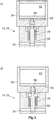
- the delivery piston 58 is displaced toward the slide 80. From a certain level, the delivery piston 58 comes into contact with the slide 80 (see FIG. 3b )).
- the slide 80 projects into the tank line 34 and reduces the flow cross-section available for the hydraulic medium, whereby the volume flow of the hydraulic medium downstream of the slide 80 is reduced (see FIG Figure 3c )).
- the reduction in the volume flow of the hydraulic medium causes the displacement speed of the piston and consequently the wedge lance 20 in the extension direction to be reduced.
- the spool 80 completely shuts off the tank line 34 (see FIG 3d figure )), so that the extension chamber 22 can not be charged with hydraulic medium. Consequently, the wedge lance 20 can no longer be moved in the extension direction and the shift speed is reduced to zero. Extending the wedge lance 20 without adequate lubrication is thus prevented.
- the protective device 74 is integrated in the line system 25 so that only the displacement speed during extension reduced or completely or almost completely reduced to zero, but not the displacement speed when retracting the piston or the wedge lance 20. A retraction is thus possible even if no lubricant is present in the lubricant chamber 60.
- the line system 25 includes a bypass line 81, with which the throttle 76 can be bypassed.
- a further check valve 84 is present, which ensures that when extending the wedge lance 20, the hydraulic medium has to flow through the throttle 76. When retracting the wedge lance 20, the hydraulic medium flows through the bypass line 81 and not the throttle 76 when the flow cross-section in the throttle 76 is reduced.
- the splitting device 10 further has a 6/2-filling valve 82, which is switchable between an operating position and a filling position.
- the 6/2-filling valve 82 is spring-actuated in the operating position.
- 6/2-filling valve 82 is connected to the filling line 48 and the discharge line 54.
- the pressure line 32 and the tank line 34 are connected to the 6/2-filling valve 82.
- the 6/2-filling valve 82 releases the discharge line 54 while it blocks the filling line 48 and separates the pressure line 32 from the tank line 34.
- the 6/2-filling valve 82 blocks the discharge line 54, while the filling line 48 releases, so that the lubricant in the Lubricant chamber 60 is introduced. Furthermore, the 6/2-filling valve 82 connects in the filling position, the pressure line 32 and the tank line 34, whereby they are depressurized. This ensures that in the pressure chamber 62 no pressure is applied, so that the lubricant can be filled, for example with a grease syringe without much effort in the lubricant chamber 60.
- the lubricant reservoir 46 may also be designed as an exchangeable lubricant cartridge. In this case, no filling of the lubricant reservoir 46 in the manner described above is necessary. The provision of the 6/2-filling valve 82 is not required in this case.
- the metering device 64 can be adjusted so that a volume of 0 to 8 cm 3 can be deployed per retraction. An amount of 0.7 to 0.8 cm 3 per entry has been found sufficient for most applications.
- the lubricant chamber 60 may be configured to provide a volume of 0.7 L for the lubricant.
- the protection device 74 may be configured such that the displacement speed is reduced when 15 to 20% of the maximum volume of lubricant is still present in the lubricant chamber 60.
- the slide 80 and the spring 78, with which the slide 80 are biased, can be formed so that from the beginning of the cross-section reduction to the complete closing of the tank line 34, the wedge lance 20 can still be extended and retracted 15 to 20 times when the Metering device 64 is set so that it emits the maximum volume of lubricant.
- pressure line 32 and the tank line 34 with a pressure booster, also called booster connected, which increases the pressure of the hydraulic medium.
- the pressure booster is controlled so that it is no longer activated when the cross-section of the tank line 34 is reduced.
Landscapes
- Engineering & Computer Science (AREA)
- Mining & Mineral Resources (AREA)
- General Engineering & Computer Science (AREA)
- Mechanical Engineering (AREA)
- Life Sciences & Earth Sciences (AREA)
- General Life Sciences & Earth Sciences (AREA)
- Geochemistry & Mineralogy (AREA)
- Geology (AREA)
- Physics & Mathematics (AREA)
- Fluid Mechanics (AREA)
- Percussive Tools And Related Accessories (AREA)
Applications Claiming Priority (1)
| Application Number | Priority Date | Filing Date | Title |
|---|---|---|---|
| DE102017108238.7A DE102017108238B3 (de) | 2017-04-18 | 2017-04-18 | Hydraulisch betriebenes Spaltgerät |
Publications (2)
| Publication Number | Publication Date |
|---|---|
| EP3392010A1 true EP3392010A1 (fr) | 2018-10-24 |
| EP3392010B1 EP3392010B1 (fr) | 2019-08-28 |
Family
ID=61563145
Family Applications (1)
| Application Number | Title | Priority Date | Filing Date |
|---|---|---|---|
| EP18159261.9A Active EP3392010B1 (fr) | 2017-04-18 | 2018-02-28 | Appareil de fendage hydraulique |
Country Status (3)
| Country | Link |
|---|---|
| US (1) | US10612377B2 (fr) |
| EP (1) | EP3392010B1 (fr) |
| DE (1) | DE102017108238B3 (fr) |
Families Citing this family (3)
| Publication number | Priority date | Publication date | Assignee | Title |
|---|---|---|---|---|
| CN110307463B (zh) * | 2019-07-19 | 2024-07-02 | 湖南烈岩科技有限公司 | 应用于劈裂装置上的润滑剂注油系统 |
| CN112610198B (zh) * | 2020-12-17 | 2022-02-25 | 中国矿业大学 | 一种煤层机械起裂与水力驱动协同靶向压裂装置及方法 |
| CN120273715B (zh) * | 2025-06-10 | 2025-08-05 | 山东黄金集团蓬莱矿业有限公司 | 一种金矿开采液压劈裂机 |
Citations (5)
| Publication number | Priority date | Publication date | Assignee | Title |
|---|---|---|---|---|
| US3743357A (en) * | 1971-11-26 | 1973-07-03 | Fletcher H Co | Reciprocating wedge structure including lubricant supply means |
| SU1093809A1 (ru) * | 1983-04-08 | 1984-05-23 | Всесоюзный научно-исследовательский институт нерудных строительных материалов и гидромеханизации | Гидроклиновое устройство дл разрушени монолитных объектов |
| SU1126694A1 (ru) * | 1983-11-24 | 1984-11-30 | Всесоюзный научно-исследовательский институт нерудных строительных материалов и гидромеханизации | Гидроклиновое устройство дл разрушени монолитных объектов |
| SU1265325A1 (ru) * | 1985-04-15 | 1986-10-23 | Всесоюзный научно-исследовательский институт нерудных строительных материалов и гидромеханизации | Устройство дл разрушени монолитных объектов |
| SU1266984A1 (ru) * | 1985-06-04 | 1986-10-30 | Ивано-Франковский Институт Нефти И Газа | Гидравлический клин |
Family Cites Families (8)
| Publication number | Priority date | Publication date | Assignee | Title |
|---|---|---|---|---|
| DE3939785A1 (de) | 1989-12-01 | 1991-06-06 | Krupp Maschinentechnik | Automatische schmiereinrichtung fuer den meissel eines hydraulischen schlagwerks |
| US7313956B1 (en) * | 2004-02-09 | 2008-01-01 | Metco Engineering Inc. | Lubrication system |
| GB0417421D0 (en) | 2004-08-05 | 2004-09-08 | Rolls Royce Plc | Method of processing oscillatory data |
| EP1626225B1 (fr) | 2004-08-12 | 2012-02-15 | Baier & Köppel GmbH & Co. | Dispositif de distribution de lubrifiant |
| FI121758B (fi) * | 2008-11-21 | 2011-03-31 | Kirnuvuori Oy | Halkaisukiila |
| WO2012024503A1 (fr) * | 2010-08-19 | 2012-02-23 | Caterpillar Inc. | Système de lubrification pour outil de concassage |
| US9217341B2 (en) * | 2013-08-15 | 2015-12-22 | Caterpillar Inc. | Lubrication system for tool |
| WO2017147563A1 (fr) * | 2016-02-26 | 2017-08-31 | Beaton Curtis L | Procédé et appareil servant à fendre ou cliver la roche |
-
2017
- 2017-04-18 DE DE102017108238.7A patent/DE102017108238B3/de not_active Expired - Fee Related
-
2018
- 2018-02-27 US US15/906,119 patent/US10612377B2/en active Active
- 2018-02-28 EP EP18159261.9A patent/EP3392010B1/fr active Active
Patent Citations (5)
| Publication number | Priority date | Publication date | Assignee | Title |
|---|---|---|---|---|
| US3743357A (en) * | 1971-11-26 | 1973-07-03 | Fletcher H Co | Reciprocating wedge structure including lubricant supply means |
| SU1093809A1 (ru) * | 1983-04-08 | 1984-05-23 | Всесоюзный научно-исследовательский институт нерудных строительных материалов и гидромеханизации | Гидроклиновое устройство дл разрушени монолитных объектов |
| SU1126694A1 (ru) * | 1983-11-24 | 1984-11-30 | Всесоюзный научно-исследовательский институт нерудных строительных материалов и гидромеханизации | Гидроклиновое устройство дл разрушени монолитных объектов |
| SU1265325A1 (ru) * | 1985-04-15 | 1986-10-23 | Всесоюзный научно-исследовательский институт нерудных строительных материалов и гидромеханизации | Устройство дл разрушени монолитных объектов |
| SU1266984A1 (ru) * | 1985-06-04 | 1986-10-30 | Ивано-Франковский Институт Нефти И Газа | Гидравлический клин |
Also Published As
| Publication number | Publication date |
|---|---|
| EP3392010B1 (fr) | 2019-08-28 |
| US10612377B2 (en) | 2020-04-07 |
| DE102017108238B3 (de) | 2018-07-12 |
| US20190024507A1 (en) | 2019-01-24 |
Similar Documents
| Publication | Publication Date | Title |
|---|---|---|
| EP3392010B1 (fr) | Appareil de fendage hydraulique | |
| DE10328286B4 (de) | Hydraulischer Schildausbau | |
| DE2024287A1 (de) | Hydraulischer Steuerkreislauf | |
| DE1943910A1 (de) | Druckmittelgesteuerter Vorschubantrieb einer Bohrvorrichtung | |
| EP2725236B1 (fr) | Unité télescopique avec fonction supplémentaire | |
| WO1986001260A1 (fr) | Pompe duplex a piston | |
| DE202017102305U1 (de) | Hydraulisch betriebenes Spaltgerät | |
| DE3002818A1 (de) | Einrichtung zur steuerung hydraulischer vorschubzylinder, insbesondere fuer den vorschub von schiebekappen eines schreitausbaus | |
| DE202009006299U1 (de) | Hydrauliksystem sowie mobile Baumaschine | |
| EP1626225B1 (fr) | Dispositif de distribution de lubrifiant | |
| DE1483957A1 (de) | Rueckeinrichtung fuer die Fuehrung einer im untertaegigen Strebbau eingesetzten Gewinnungsmaschine | |
| DE102011054616B3 (de) | Hydraulisch angetriebene Anordnung zum linearen Bewegen eines Massekörpers | |
| DE3448016C2 (fr) | ||
| WO2020120234A1 (fr) | Pompe à piston et procédé pour faire fonctionner une pompe à piston | |
| DE102016201146B3 (de) | Teleskop-Ausleger mit autarker Schmiereinrichtung | |
| EP3045738A1 (fr) | Verin hydraulique | |
| EP1577555B1 (fr) | Dispositif de pompage pour un fluide | |
| AT398942B (de) | Dosiervorrichtung zur festlegung des entlade- und ladevolumens der hydraulikflüssigkeit eines dosierbaren energiespeichers einer hydraulikanlage, insbesondere einer hydraulischen schlagpresse | |
| DE102015110017A1 (de) | Vorrichtung zur Förderung des Abbaubodens in einer Schildvortriebsmaschine (SVM) | |
| DE3927332A1 (de) | Vorrichtung zum pneumatischen ausbringen von hydromechanisch im dichtstrom gefoerdertem beton | |
| DE19749275B4 (de) | Dosierhochdrucksetzpistole | |
| DE3808326C2 (fr) | ||
| DE2122454C3 (de) | Steuervorrichtung für einen Hubkolben | |
| DE3401003A1 (de) | Einrichtung zur steuerung der schiebekappenzylinder hydraulischer schreitausbaueinheiten | |
| DE102016114680A1 (de) | Vorrichtung zum Erzeugen eines pulsierenden Hydraulikfluiddruckes |
Legal Events
| Date | Code | Title | Description |
|---|---|---|---|
| PUAI | Public reference made under article 153(3) epc to a published international application that has entered the european phase |
Free format text: ORIGINAL CODE: 0009012 |
|
| STAA | Information on the status of an ep patent application or granted ep patent |
Free format text: STATUS: THE APPLICATION HAS BEEN PUBLISHED |
|
| STAA | Information on the status of an ep patent application or granted ep patent |
Free format text: STATUS: REQUEST FOR EXAMINATION WAS MADE |
|
| AK | Designated contracting states |
Kind code of ref document: A1 Designated state(s): AL AT BE BG CH CY CZ DE DK EE ES FI FR GB GR HR HU IE IS IT LI LT LU LV MC MK MT NL NO PL PT RO RS SE SI SK SM TR |
|
| AX | Request for extension of the european patent |
Extension state: BA ME |
|
| 17P | Request for examination filed |
Effective date: 20180920 |
|
| RBV | Designated contracting states (corrected) |
Designated state(s): AL AT BE BG CH CY CZ DE DK EE ES FI FR GB GR HR HU IE IS IT LI LT LU LV MC MK MT NL NO PL PT RO RS SE SI SK SM TR |
|
| GRAP | Despatch of communication of intention to grant a patent |
Free format text: ORIGINAL CODE: EPIDOSNIGR1 |
|
| STAA | Information on the status of an ep patent application or granted ep patent |
Free format text: STATUS: GRANT OF PATENT IS INTENDED |
|
| RIC1 | Information provided on ipc code assigned before grant |
Ipc: B28D 1/00 20060101AFI20190214BHEP Ipc: E21C 37/04 20060101ALI20190214BHEP |
|
| INTG | Intention to grant announced |
Effective date: 20190318 |
|
| GRAS | Grant fee paid |
Free format text: ORIGINAL CODE: EPIDOSNIGR3 |
|
| GRAA | (expected) grant |
Free format text: ORIGINAL CODE: 0009210 |
|
| STAA | Information on the status of an ep patent application or granted ep patent |
Free format text: STATUS: THE PATENT HAS BEEN GRANTED |
|
| AK | Designated contracting states |
Kind code of ref document: B1 Designated state(s): AL AT BE BG CH CY CZ DE DK EE ES FI FR GB GR HR HU IE IS IT LI LT LU LV MC MK MT NL NO PL PT RO RS SE SI SK SM TR |
|
| REG | Reference to a national code |
Ref country code: GB Ref legal event code: FG4D Free format text: NOT ENGLISH |
|
| REG | Reference to a national code |
Ref country code: CH Ref legal event code: EP |
|
| REG | Reference to a national code |
Ref country code: DE Ref legal event code: R096 Ref document number: 502018000161 Country of ref document: DE |
|
| REG | Reference to a national code |
Ref country code: AT Ref legal event code: REF Ref document number: 1171839 Country of ref document: AT Kind code of ref document: T Effective date: 20190915 |
|
| REG | Reference to a national code |
Ref country code: IE Ref legal event code: FG4D Free format text: LANGUAGE OF EP DOCUMENT: GERMAN |
|
| REG | Reference to a national code |
Ref country code: CH Ref legal event code: NV Representative=s name: R.A. EGLI AND CO, PATENTANWAELTE, CH |
|
| REG | Reference to a national code |
Ref country code: SE Ref legal event code: TRGR |
|
| REG | Reference to a national code |
Ref country code: NL Ref legal event code: MP Effective date: 20190828 |
|
| REG | Reference to a national code |
Ref country code: LT Ref legal event code: MG4D |
|
| REG | Reference to a national code |
Ref country code: NO Ref legal event code: T2 Effective date: 20190828 |
|
| PG25 | Lapsed in a contracting state [announced via postgrant information from national office to epo] |
Ref country code: HR Free format text: LAPSE BECAUSE OF FAILURE TO SUBMIT A TRANSLATION OF THE DESCRIPTION OR TO PAY THE FEE WITHIN THE PRESCRIBED TIME-LIMIT Effective date: 20190828 Ref country code: LT Free format text: LAPSE BECAUSE OF FAILURE TO SUBMIT A TRANSLATION OF THE DESCRIPTION OR TO PAY THE FEE WITHIN THE PRESCRIBED TIME-LIMIT Effective date: 20190828 Ref country code: PT Free format text: LAPSE BECAUSE OF FAILURE TO SUBMIT A TRANSLATION OF THE DESCRIPTION OR TO PAY THE FEE WITHIN THE PRESCRIBED TIME-LIMIT Effective date: 20191230 Ref country code: NL Free format text: LAPSE BECAUSE OF FAILURE TO SUBMIT A TRANSLATION OF THE DESCRIPTION OR TO PAY THE FEE WITHIN THE PRESCRIBED TIME-LIMIT Effective date: 20190828 Ref country code: BG Free format text: LAPSE BECAUSE OF FAILURE TO SUBMIT A TRANSLATION OF THE DESCRIPTION OR TO PAY THE FEE WITHIN THE PRESCRIBED TIME-LIMIT Effective date: 20191128 |
|
| PG25 | Lapsed in a contracting state [announced via postgrant information from national office to epo] |
Ref country code: AL Free format text: LAPSE BECAUSE OF FAILURE TO SUBMIT A TRANSLATION OF THE DESCRIPTION OR TO PAY THE FEE WITHIN THE PRESCRIBED TIME-LIMIT Effective date: 20190828 Ref country code: ES Free format text: LAPSE BECAUSE OF FAILURE TO SUBMIT A TRANSLATION OF THE DESCRIPTION OR TO PAY THE FEE WITHIN THE PRESCRIBED TIME-LIMIT Effective date: 20190828 Ref country code: LV Free format text: LAPSE BECAUSE OF FAILURE TO SUBMIT A TRANSLATION OF THE DESCRIPTION OR TO PAY THE FEE WITHIN THE PRESCRIBED TIME-LIMIT Effective date: 20190828 Ref country code: RS Free format text: LAPSE BECAUSE OF FAILURE TO SUBMIT A TRANSLATION OF THE DESCRIPTION OR TO PAY THE FEE WITHIN THE PRESCRIBED TIME-LIMIT Effective date: 20190828 Ref country code: GR Free format text: LAPSE BECAUSE OF FAILURE TO SUBMIT A TRANSLATION OF THE DESCRIPTION OR TO PAY THE FEE WITHIN THE PRESCRIBED TIME-LIMIT Effective date: 20191129 Ref country code: IS Free format text: LAPSE BECAUSE OF FAILURE TO SUBMIT A TRANSLATION OF THE DESCRIPTION OR TO PAY THE FEE WITHIN THE PRESCRIBED TIME-LIMIT Effective date: 20191228 |
|
| PG25 | Lapsed in a contracting state [announced via postgrant information from national office to epo] |
Ref country code: TR Free format text: LAPSE BECAUSE OF FAILURE TO SUBMIT A TRANSLATION OF THE DESCRIPTION OR TO PAY THE FEE WITHIN THE PRESCRIBED TIME-LIMIT Effective date: 20190828 |
|
| PG25 | Lapsed in a contracting state [announced via postgrant information from national office to epo] |
Ref country code: RO Free format text: LAPSE BECAUSE OF FAILURE TO SUBMIT A TRANSLATION OF THE DESCRIPTION OR TO PAY THE FEE WITHIN THE PRESCRIBED TIME-LIMIT Effective date: 20190828 Ref country code: PL Free format text: LAPSE BECAUSE OF FAILURE TO SUBMIT A TRANSLATION OF THE DESCRIPTION OR TO PAY THE FEE WITHIN THE PRESCRIBED TIME-LIMIT Effective date: 20190828 Ref country code: EE Free format text: LAPSE BECAUSE OF FAILURE TO SUBMIT A TRANSLATION OF THE DESCRIPTION OR TO PAY THE FEE WITHIN THE PRESCRIBED TIME-LIMIT Effective date: 20190828 Ref country code: DK Free format text: LAPSE BECAUSE OF FAILURE TO SUBMIT A TRANSLATION OF THE DESCRIPTION OR TO PAY THE FEE WITHIN THE PRESCRIBED TIME-LIMIT Effective date: 20190828 |
|
| PG25 | Lapsed in a contracting state [announced via postgrant information from national office to epo] |
Ref country code: IS Free format text: LAPSE BECAUSE OF FAILURE TO SUBMIT A TRANSLATION OF THE DESCRIPTION OR TO PAY THE FEE WITHIN THE PRESCRIBED TIME-LIMIT Effective date: 20200224 Ref country code: CZ Free format text: LAPSE BECAUSE OF FAILURE TO SUBMIT A TRANSLATION OF THE DESCRIPTION OR TO PAY THE FEE WITHIN THE PRESCRIBED TIME-LIMIT Effective date: 20190828 Ref country code: SM Free format text: LAPSE BECAUSE OF FAILURE TO SUBMIT A TRANSLATION OF THE DESCRIPTION OR TO PAY THE FEE WITHIN THE PRESCRIBED TIME-LIMIT Effective date: 20190828 Ref country code: SK Free format text: LAPSE BECAUSE OF FAILURE TO SUBMIT A TRANSLATION OF THE DESCRIPTION OR TO PAY THE FEE WITHIN THE PRESCRIBED TIME-LIMIT Effective date: 20190828 |
|
| REG | Reference to a national code |
Ref country code: DE Ref legal event code: R097 Ref document number: 502018000161 Country of ref document: DE |
|
| PLBE | No opposition filed within time limit |
Free format text: ORIGINAL CODE: 0009261 |
|
| STAA | Information on the status of an ep patent application or granted ep patent |
Free format text: STATUS: NO OPPOSITION FILED WITHIN TIME LIMIT |
|
| PG2D | Information on lapse in contracting state deleted |
Ref country code: IS |
|
| 26N | No opposition filed |
Effective date: 20200603 |
|
| REG | Reference to a national code |
Ref country code: BE Ref legal event code: MM Effective date: 20200229 |
|
| PG25 | Lapsed in a contracting state [announced via postgrant information from national office to epo] |
Ref country code: MC Free format text: LAPSE BECAUSE OF FAILURE TO SUBMIT A TRANSLATION OF THE DESCRIPTION OR TO PAY THE FEE WITHIN THE PRESCRIBED TIME-LIMIT Effective date: 20190828 Ref country code: LU Free format text: LAPSE BECAUSE OF NON-PAYMENT OF DUE FEES Effective date: 20200228 |
|
| PG25 | Lapsed in a contracting state [announced via postgrant information from national office to epo] |
Ref country code: BE Free format text: LAPSE BECAUSE OF NON-PAYMENT OF DUE FEES Effective date: 20200229 |
|
| PGFP | Annual fee paid to national office [announced via postgrant information from national office to epo] |
Ref country code: IE Payment date: 20220216 Year of fee payment: 5 Ref country code: GB Payment date: 20220221 Year of fee payment: 5 Ref country code: DE Payment date: 20220330 Year of fee payment: 5 |
|
| PG25 | Lapsed in a contracting state [announced via postgrant information from national office to epo] |
Ref country code: MT Free format text: LAPSE BECAUSE OF FAILURE TO SUBMIT A TRANSLATION OF THE DESCRIPTION OR TO PAY THE FEE WITHIN THE PRESCRIBED TIME-LIMIT Effective date: 20190828 Ref country code: CY Free format text: LAPSE BECAUSE OF FAILURE TO SUBMIT A TRANSLATION OF THE DESCRIPTION OR TO PAY THE FEE WITHIN THE PRESCRIBED TIME-LIMIT Effective date: 20190828 |
|
| PGFP | Annual fee paid to national office [announced via postgrant information from national office to epo] |
Ref country code: FR Payment date: 20220221 Year of fee payment: 5 |
|
| PG25 | Lapsed in a contracting state [announced via postgrant information from national office to epo] |
Ref country code: MK Free format text: LAPSE BECAUSE OF FAILURE TO SUBMIT A TRANSLATION OF THE DESCRIPTION OR TO PAY THE FEE WITHIN THE PRESCRIBED TIME-LIMIT Effective date: 20190828 |
|
| REG | Reference to a national code |
Ref country code: DE Ref legal event code: R119 Ref document number: 502018000161 Country of ref document: DE |
|
| PG25 | Lapsed in a contracting state [announced via postgrant information from national office to epo] |
Ref country code: SI Free format text: LAPSE BECAUSE OF FAILURE TO SUBMIT A TRANSLATION OF THE DESCRIPTION OR TO PAY THE FEE WITHIN THE PRESCRIBED TIME-LIMIT Effective date: 20190828 |
|
| GBPC | Gb: european patent ceased through non-payment of renewal fee |
Effective date: 20230228 |
|
| REG | Reference to a national code |
Ref country code: IE Ref legal event code: MM4A |
|
| PG25 | Lapsed in a contracting state [announced via postgrant information from national office to epo] |
Ref country code: GB Free format text: LAPSE BECAUSE OF NON-PAYMENT OF DUE FEES Effective date: 20230228 |
|
| PG25 | Lapsed in a contracting state [announced via postgrant information from national office to epo] |
Ref country code: IE Free format text: LAPSE BECAUSE OF NON-PAYMENT OF DUE FEES Effective date: 20230228 Ref country code: GB Free format text: LAPSE BECAUSE OF NON-PAYMENT OF DUE FEES Effective date: 20230228 Ref country code: FR Free format text: LAPSE BECAUSE OF NON-PAYMENT OF DUE FEES Effective date: 20230228 Ref country code: DE Free format text: LAPSE BECAUSE OF NON-PAYMENT OF DUE FEES Effective date: 20230901 |
|
| REG | Reference to a national code |
Ref country code: CH Ref legal event code: U11 Free format text: ST27 STATUS EVENT CODE: U-0-0-U10-U11 (AS PROVIDED BY THE NATIONAL OFFICE) Effective date: 20260301 |
|
| PGFP | Annual fee paid to national office [announced via postgrant information from national office to epo] |
Ref country code: SE Payment date: 20260218 Year of fee payment: 9 |
|
| PGFP | Annual fee paid to national office [announced via postgrant information from national office to epo] |
Ref country code: NO Payment date: 20260217 Year of fee payment: 9 |
|
| PGFP | Annual fee paid to national office [announced via postgrant information from national office to epo] |
Ref country code: AT Payment date: 20260216 Year of fee payment: 9 |
|
| PGFP | Annual fee paid to national office [announced via postgrant information from national office to epo] |
Ref country code: FI Payment date: 20260217 Year of fee payment: 9 Ref country code: IT Payment date: 20260227 Year of fee payment: 9 |
|
| PGFP | Annual fee paid to national office [announced via postgrant information from national office to epo] |
Ref country code: CH Payment date: 20260301 Year of fee payment: 9 |