EP3392068A1 - Système de suspension - Google Patents
Système de suspension Download PDFInfo
- Publication number
- EP3392068A1 EP3392068A1 EP17166772.8A EP17166772A EP3392068A1 EP 3392068 A1 EP3392068 A1 EP 3392068A1 EP 17166772 A EP17166772 A EP 17166772A EP 3392068 A1 EP3392068 A1 EP 3392068A1
- Authority
- EP
- European Patent Office
- Prior art keywords
- assembly
- arm
- upright
- respect
- control arm
- Prior art date
- Legal status (The legal status is an assumption and is not a legal conclusion. Google has not performed a legal analysis and makes no representation as to the accuracy of the status listed.)
- Withdrawn
Links
Images







Classifications
-
- B—PERFORMING OPERATIONS; TRANSPORTING
- B60—VEHICLES IN GENERAL
- B60G—VEHICLE SUSPENSION ARRANGEMENTS
- B60G7/00—Pivoted suspension arms; Accessories thereof
- B60G7/006—Attaching arms to sprung or unsprung part of vehicle, characterised by comprising attachment means controlled by an external actuator, e.g. a fluid or electrical motor
-
- B—PERFORMING OPERATIONS; TRANSPORTING
- B60—VEHICLES IN GENERAL
- B60F—VEHICLES FOR USE BOTH ON RAIL AND ON ROAD; VEHICLES CAPABLE OF TRAVELLING IN OR ON DIFFERENT MEDIA, e.g. AMPHIBIOUS VEHICLES
- B60F5/00—Other vehicles capable of travelling in or on different media
- B60F5/02—Other vehicles capable of travelling in or on different media convertible into aircraft
-
- B—PERFORMING OPERATIONS; TRANSPORTING
- B60—VEHICLES IN GENERAL
- B60G—VEHICLE SUSPENSION ARRANGEMENTS
- B60G3/00—Resilient suspensions for a single wheel
- B60G3/18—Resilient suspensions for a single wheel with two or more pivoted arms, e.g. parallelogram
- B60G3/20—Resilient suspensions for a single wheel with two or more pivoted arms, e.g. parallelogram all arms being rigid
-
- B—PERFORMING OPERATIONS; TRANSPORTING
- B64—AIRCRAFT; AVIATION; COSMONAUTICS
- B64C—AEROPLANES; HELICOPTERS
- B64C37/00—Convertible aircraft
-
- B—PERFORMING OPERATIONS; TRANSPORTING
- B60—VEHICLES IN GENERAL
- B60F—VEHICLES FOR USE BOTH ON RAIL AND ON ROAD; VEHICLES CAPABLE OF TRAVELLING IN OR ON DIFFERENT MEDIA, e.g. AMPHIBIOUS VEHICLES
- B60F2301/00—Retractable wheels
- B60F2301/04—Retractable wheels pivotally
-
- B—PERFORMING OPERATIONS; TRANSPORTING
- B60—VEHICLES IN GENERAL
- B60G—VEHICLE SUSPENSION ARRANGEMENTS
- B60G2200/00—Indexing codes relating to suspension types
- B60G2200/10—Independent suspensions
- B60G2200/14—Independent suspensions with lateral arms
- B60G2200/144—Independent suspensions with lateral arms with two lateral arms forming a parallelogram
-
- B—PERFORMING OPERATIONS; TRANSPORTING
- B60—VEHICLES IN GENERAL
- B60G—VEHICLE SUSPENSION ARRANGEMENTS
- B60G2204/00—Indexing codes related to suspensions per se or to auxiliary parts
- B60G2204/10—Mounting of suspension elements
- B60G2204/12—Mounting of springs or dampers
- B60G2204/13—Mounting of springs or dampers with the spring, i.e. coil spring, or damper horizontally mounted
-
- B—PERFORMING OPERATIONS; TRANSPORTING
- B60—VEHICLES IN GENERAL
- B60G—VEHICLE SUSPENSION ARRANGEMENTS
- B60G2204/00—Indexing codes related to suspensions per se or to auxiliary parts
- B60G2204/40—Auxiliary suspension parts; Adjustment of suspensions
- B60G2204/421—Pivoted lever mechanisms for mounting suspension elements, e.g. Watt linkage
-
- B—PERFORMING OPERATIONS; TRANSPORTING
- B60—VEHICLES IN GENERAL
- B60G—VEHICLE SUSPENSION ARRANGEMENTS
- B60G2204/00—Indexing codes related to suspensions per se or to auxiliary parts
- B60G2204/40—Auxiliary suspension parts; Adjustment of suspensions
- B60G2204/47—Means for retracting the suspension
-
- B—PERFORMING OPERATIONS; TRANSPORTING
- B60—VEHICLES IN GENERAL
- B60G—VEHICLE SUSPENSION ARRANGEMENTS
- B60G2300/00—Indexing codes relating to the type of vehicle
- B60G2300/16—Aeroplanes
Definitions
- This invention relates to vehicles that are configurable for air use (flying) and road use (driving). Such vehicles are commonly known as flying cars or roadable aircraft (hereafter “flying cars”).
- flying cars or roadable aircraft
- the invention relates to a configurable light unit that can be deployed in different positions for road use and air use.
- Suspension systems for flying cars may be required to meet a number of requirements, including a relatively large vertical travel range, distinct ride height configurations for road use and take-off or landing, further vertical and lateral retraction for in-flight drag reduction, an ability to cope with significant vertical input on heavy landings, the provision of front wheel drive, sufficient steering lock to minimise turning circle, limited space availability, and a wheel fairing that moves with the wheel in bump and lateral retraction travel, but not in steer motion.
- This invention aims to address or mitigate some or all of these issues.
- a first aspect of the invention provides a wheel suspension system for mounting a wheel on a vehicle body, the system comprising: an upright assembly for mounting the wheel; a lower arm assembly comprising: a lower control arm; and a storage arm; a mounting structure connecting the lower arm assembly to the upright assembly; an upper control arm; and an adjustable suspension assembly pivotally connected to the upright assembly or lower control arm assembly and pivotally connected to the body; wherein one end of the lower control arm is pivotally connected to the body, and the other end of the lower control arm is connected to the mounting structure to be pivotable about a first axis; the mounting structure is connected to the upright assembly to be pivotable about a second axis that is substantially perpendicular to the first axis; the storage arm is pivotally connected to the lower control arm at one end, and is moveably connected to the body under control of an actuator at the other end; and the upper control arm having a pivot connection to an upper part of the upright assembly at one and, and a pivot connection to the body at the other end; and wherein the lateral position
- the upright assembly can comprise a steerable upright on which the wheel is mounted, and a secondary upright, the steerable upright being pivotally mounted on the secondary upright.
- the secondary upright can be omitted, the mounting structure being connected to the steerable upright.
- the storage arm can be pivotally connected to the lower control arm at one end, and has a slideable pivot connection to the body at the other end, the slideable pivot connection being moveable longitudinally with respect to the body; and wherein the lateral position of the upright assembly with respect to the body is adjustable by movement of the slideable pivot connection of the storage arm with respect to the body
- the slideable pivot connection can comprise a rail connected to the body extending in a longitudinal direction, and a carriage slideably mounted on the rail and providing the pivot connection for the stowage arm, and an actuator for moving the carriage along the rail.
- the rail can extend ahead of the wheel on the body.
- the adjustable suspension assembly can comprise a pushrod and an adjustable spring and damper connected between the pushrod and the body.
- the assembly can further comprise a rocker pivotally connected to the body, the adjustable spring and damper being connected on one side of the rocker, and the pushrod being connected on an opposite side of the rocker.
- the spring and damper may connect direclty to the secondary upright or to the lower control arm assembly.
- a latching mechanism can be provided on the rocker for holding the upright assembly in a fixed position with respect to the body.
- the upright assembly can be moveable between a first position that is laterally extended with respect to the body and vertically lowered with respect to the body, and a second position is laterally retracted with respect to the body and vertically raised with respect to the body; wherein, when the upright assembly is in the first position, the lower arm assembly is in a first configuration in which the slideable pivot connection is closer to the pivot connection of the lower control arm, and the pushrod is extended, and when the upright assembly is in the second position, the lower arm assembly is in a second configuration in which the slideable pivot connection is further from the pivot connection of the lower control arm, and the pushrod is retracted.
- the upright assembly can also be moveable to an intermediate position between the first and second positions.
- the storage arm comprises an inner part and an outer part connected by means of a hinge, the inner part including a connection to an actuator rod of an actuator mechanims; wherein operation of the actuator mechanism to a first position holds the arm in a straight configuration to exented the upright assembly laterally from the body, and operation of the actuator mechanism to a second position flods the storage arm to move the upright aseembly laterally towards the vehicle body.
- a second aspect provides vehicle configurable for air or road use, comprising: a body; a pair of road wheels located on either side of a front region of the body, each wheel being mounted on the body by means of a suspension system according to the first aspect and moveable between a first configuration in which the wheels are positioned close to the body for air use, and a second configuration in which the wheels are extended laterally from the body for supporting the body when configured for road use, the spacing between the wheels being greater in the second configuration than in the first configuration.
- the vehicle can further comprise foldable wings that are moveable between an extended position for air use, and a retracted position for road use.
- the vehicle can further comprise one or more drive motors connected to provide traction drive to the wheels, wherein the one or more drive motors are connected to the wheels by means of drive shaft extending through the upright assemblies.
- the suspension system can be configurable into any of: a first position in which the wheels are laterally extended with respect to the body and vertically lowered with respect to the body to place the vehicle in an attitude for take off or landing, an intermediate position in which the wheels are laterally extended with respect to the body and vertically lowered with respect to the body to place the vehicle in an attitude for road use; and a second position in which the wheels are laterally retracted with respect to the body and vertically raised with respect to the body for air use.
- an aircraft comprising a convertible vehicle (a flying car) is shown, in a flight configuration ( Figure 1 ) and a road use configuration ( Figure 2 ).
- the flying car comprises a body structure 10 providing a crew compartment 12 and housing a motor (not shown) and propeller shaft (not shown) that extends from the motor to the rear 14 of the body structure 10, where the propeller is mounted as is described below.
- Wings 16 for providing lift and control (via ailerons, not shown) are mounted at the top of the body 10 immediately behind the crew compartment 12.
- the wings 16 can be moved between an extended position for flight use ( Figure 1 ), and a folded position for road use ( Figure 2 ). In the folded position, the wings lie along the top of the body 10, the long axis of the wings lying substantially parallel to the long axis of the body 10.
- the folding mechanism is substantially as described in WO 2013/03240 .
- Front wheels 26 are mounted on the body structure 10.
- the front wheels are both steerable and driven.
- Each wheel 26 has an associated fairing 27.
- the front wheels 26 and fairing 27 can be moved between a retracted position ( Figure 1 ) in which they are positioned close to the body 10, the fairing 27 fitting closely with the outer surface of the body 10, to reduce drag in flight; and an open position ( Figure 2 ) in which they are positioned for improved traction and control for road use.
- the fairing 27 In the open position, the fairing 27 can be positioned with respect to the wheels 26 so as to comply with road use regulatory requirements with regard to exposure of the wheels. It is also possible to include marker lights and direction indicator repeaters on the fairing 27.
- the suspension system by which the wheels are mounted on the body both provides normal suspension function in road use, and a mechanism by which the wheels can be retracted to reduce drag in flight use, and extended for landing and road use, as is described in further detail below.
- Figures 3 - 6 show the main components of an example of the suspension system.
- the system 100 shown in Figures 3 - 6 comprises an upright assembly 101 comprising a steerable upright 102 and a secondary upright 103.
- a wheel hub 104, brake disc 106 and calliper 108, and wheel and tyre 110 are mounted on the steerable upright 102.
- a drive shaft 112 connects to the hub 104 though the upright assembly 101.
- a lower arm assembly 114 comprising a lower control arm 116 and a storage arm 118, is connected to the lower part of the secondary upright 103 via a mounting structure 120.
- An upper control arm 122 is connected to an upper part of the secondary upright 103.
- a steering mechanism comprising a link 124, track rod 126, and steering idler 128 provide a connection between a steering rack (not shown) and the steerable upright 102.
- a wheel fairing (27 described in Figures 1 and 2 ) can be mounted on the secondary upright 103.
- the upright assembly 101 comprises two suspension uprights 102, 103.
- the hub 104, brake disc 106, and wheel and tyre assembly 110 is attached to the steerable upright 102 via a conventional wheel bearing
- the steerable upright 102 is pivotally jointed to the secondary upright 103 via an upper spherical joint 130 and a lower cylindrical joint 132, which together act to define the steer axis A-A of the system as is shown in Figure 7 .
- the secondary upright 103 can be controlled to provide bump and lateral retraction travel relative to the vehicle body, while remaining substantially aligned with the vehicle body in the steer (vertical axis rotation) sense. With bump motion, the suspension linkages control the secondary upright 103 to deliver wheel assembly camber change and track change / roll centre migration, while constraining its steer motion.
- the mounting structure 120 is joined between the lower control arm 116 and the secondary upright 103 with a cylindrical joint 134 having an axis B-B that is substantially parallel to the vehicle longitudinal axis, as is shown in Figures 8 and 9 .
- This axis permits camber motion while constraining steer motion.
- the mounting structure 120 connects to the lower control arm 116 via a second cylindrical joint 136 with a substantially vertical axis C-C, which comes into play during lateral retraction of the suspension system.
- the mounting structure 120 is controlled in steer (rotation about its vertical axis C-C) by a toe link 138, to which it is connected via a spherical joint 140.
- the lower control arm 116 is pivotally connected to the body via a spherical joint 141.
- the lower control arm 116, toe link 138, mounting structure 120, and stowage arm 118 do not move relative to one another, effectively forming a single lower arm assembly 114, the body mounts of the lower control arm 116, toe link 138, and stowage arm 118 lying along a single straight line about which the lower arm assembly articulates in suspension motion.
- the lower arm assembly 114 controls the position of the secondary upright 103 in all respects other than camber (rotation about the horizontal axis B-B of the mounting structure 120), which is governed in cooperation with the upper control arm 122. Under normal suspension motion, the system is similar to a double wishbone, or lower H-arm with upper link.
- the relationship of the components in the lower arm assembly 114 provides for lateral stowage of the system to reduce drag while in flight.
- the suspension system In addition to vertical retraction of the wheel and tyre 110 to a point higher than that seen in on-road use, the suspension system also draws the wheel inboard. While doing so, the suspension components remain at substantially the same steer orientation relative to the vehicle body. Hence, an approximately parallel motion is described by the lower control arm 116 and toe link 138, controlling secondary upright motion.
- the upper control arm 122 and steering track rod 128 are configured to move in sympathy with this action, so that parasitic camber of the wheel / fairing assembly and steer of the wheel 110 are minimised.
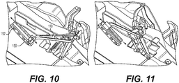
- Control of the stowage action is achieved through substantially fore and aft motion of the inboard mount/carriage 150 of the stowage arm 118 along a rail system 152, as is shown in Figures 10 - 14 .
- the stowage arm 118 is connected to the carriage by a cylindrical joint 154.
- the stowage arm 118 joins to the lower control arm 116 by a cylindrical joint 156. This provides rotational constraint to the to lower control arm 116 about its own axis, and hence pitch constraint to the mounting structure 120 and secondary upright 103.
- the carriage 150 is provided with actuation means for the sliding motion, and for latching at its extremes of motion.
- the upright assembly (not shown) will be at its furthest lateral extent from the body ( Figure 12 ).
- the upright assembly is drawn towards the body ( Figure 13 ), until the carriage 150 reaches the forward most end of the rail 152, at which time the wheel will be fully retracted into the body ( Figure 14 ).
- the toe link 138 ensures that axis B-B of the mounting structure 120 remains substantially parallel to the vehicle axis, and the lower control arm 116 and track rod 126 remain substantially parallel through the movement such that steering direction does not change.
- the pushrod assembly 142 comprises a pushrod 144, that is pivotally connected at one end to the secondary upright 103 via a spherical joint 145, that transmits force and motion to a rocker 146 at the other end via a spherical/elastomeric joint 147.
- the rocker 146 is, in turn, connected to an inboard spring and damper unit 148 via a spherical joint 149.
- the spring function is achieved by compressing a gas volume within the unit 148. Variation in ride height is achieved through altering the mass of gas within the unit 148 from a separate source (not shown). Damping is by conventional hydraulic means within the same unit.
- the rocker 146 is also connected to the body by mounting 151 including a revolute joint or bearing.
- mounting 151 including a revolute joint or bearing.
- the mounting 151 also includes a secondary upright retention system for in-flight location of the wheel and fairing assembly.
- the upper control arm 122 is pivotally connected to the body via a universal joint 158 at its inner end, and to the secondary upright 103 via a spherical joint 163 at its outer end, allowing the use of a cranked structure with a centre of mass off the axis joining the joint centres.
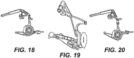
- Figures 15 - 20 The range of vertical positions is shown in Figures 15 - 20 .
- Figures 15 and 16 show the system at full road compression (full bump), which is essentially the same position as when the wheel is fully retracted by withdrawing gas from the spring/damper unit 148.
- Figures 17 and 18 show the wheel in an intermediate position for normal road use height.
- the push rod 144 forces the upright assembly 101 down so that the wheel (not shown) can be extended vertically for take-off and landing as is shown in Figures 19 and 20 .
- the lower arm assembly 114 and the upper control arm 122 ensure that the upright assembly 101 remains in substantially the same vertical alignment through the range of movements such that the camber of the wheel is not affected by the change of vertical position.
- the steering track rod 126 is connected to a steering idler 128, which in turn is driven by the steering rack 164 via a second link 124 as is shown in Figure 21 .
- a small degree of steer remains in the case of an emergency gear-up landing.
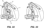
- the wheel fairing 27 is attached to the secondary upright 103 in two places: where the upper control arm 122 is connected, and with a lower stay 166, which wraps around the wheel 110 at hub centre height.
- the wheel 110 is free to turn under steering while the fairing 27 will remain parallel to the body, as is shown in Figures 16 and 17 .
- Figures 24 and 25 show an alternative embodiment of the stowage arm.
- the stowage arm 218 is pivotally connected at a fixed point 220 at its inboard end.
- the arm 218 is formed in two parts, an outer part 222, and an inner part 224 with a pivot connection 226 joining the two parts.
- the inner part 224 includes a connection 228 for an actuator rod 230 connected to a drive mechanism 232.
- the drive mechanism 232 pulls on the actuator rod 230, holding the two arm parts 222, 224 in an extended configuration.
- Operating the drive mechanism 232to push on the actuator rod 230 causes the inner part 224 to pivot around its inboard end 220, folding the arm at the pivot 226 and drawing the wheel inwardly towards the body. Extending the wheel is the reverse of this procedure.
Landscapes
- Engineering & Computer Science (AREA)
- Aviation & Aerospace Engineering (AREA)
- Mechanical Engineering (AREA)
- Transportation (AREA)
- Vehicle Body Suspensions (AREA)
Priority Applications (3)
| Application Number | Priority Date | Filing Date | Title |
|---|---|---|---|
| EP17166772.8A EP3392068A1 (fr) | 2017-04-18 | 2017-04-18 | Système de suspension |
| US16/606,637 US20200055359A1 (en) | 2017-04-18 | 2018-04-16 | Suspension system |
| PCT/EP2018/059645 WO2018192868A1 (fr) | 2017-04-18 | 2018-04-16 | Système de suspension |
Applications Claiming Priority (1)
| Application Number | Priority Date | Filing Date | Title |
|---|---|---|---|
| EP17166772.8A EP3392068A1 (fr) | 2017-04-18 | 2017-04-18 | Système de suspension |
Publications (1)
| Publication Number | Publication Date |
|---|---|
| EP3392068A1 true EP3392068A1 (fr) | 2018-10-24 |
Family
ID=58578860
Family Applications (1)
| Application Number | Title | Priority Date | Filing Date |
|---|---|---|---|
| EP17166772.8A Withdrawn EP3392068A1 (fr) | 2017-04-18 | 2017-04-18 | Système de suspension |
Country Status (3)
| Country | Link |
|---|---|
| US (1) | US20200055359A1 (fr) |
| EP (1) | EP3392068A1 (fr) |
| WO (1) | WO2018192868A1 (fr) |
Cited By (2)
| Publication number | Priority date | Publication date | Assignee | Title |
|---|---|---|---|---|
| CN112744227A (zh) * | 2021-01-21 | 2021-05-04 | 清华大学 | 一种多模态陆空两栖车辆起降控制方法及控制装置、计算机存储介质 |
| CN114475116A (zh) * | 2022-01-29 | 2022-05-13 | 复旦大学 | 一种三栖机器人 |
Families Citing this family (1)
| Publication number | Priority date | Publication date | Assignee | Title |
|---|---|---|---|---|
| CN114312182B (zh) * | 2022-01-04 | 2023-08-22 | 广东汇天航空航天科技有限公司 | 飞行汽车 |
Citations (8)
| Publication number | Priority date | Publication date | Assignee | Title |
|---|---|---|---|---|
| US20020041076A1 (en) * | 2000-09-28 | 2002-04-11 | Dietmar Becker | Wheel suspension for a motor vehicle |
| FR2844245A1 (fr) * | 2002-09-10 | 2004-03-12 | Jean Marie Obry | Vehicule universel de transport a voie, empattement et garde au sol variables |
| WO2007114877A2 (fr) | 2006-01-06 | 2007-10-11 | Terrafugia, Inc. | Aeronef susceptible d'etre converti en vehicule terrestre equipe d'ailes repliables et de pare-chocs et eclairage integres |
| GB2445552A (en) * | 2007-01-15 | 2008-07-16 | Gibbs Tech Ltd | Wheel suspension and retraction apparatus |
| WO2008155587A2 (fr) * | 2007-06-19 | 2008-12-24 | Fairfield Worldwide Ltd. | Véhicule routier à écartement variable ayant plus de trois roues |
| WO2010012285A2 (fr) * | 2008-07-28 | 2010-02-04 | Fleck Fitness Concepts Gmbh | Véhicule routier, aquatique et aérien combiné |
| WO2013003240A2 (fr) | 2011-06-28 | 2013-01-03 | Microsoft Corporation | Résumé de fils de conversation |
| WO2013032409A1 (fr) | 2011-08-30 | 2013-03-07 | Aeromobil, S.R.O. | Procédé de transformation d'un véhicule de transport hybride terrestre et aérien et véhicule de transport hybride |
-
2017
- 2017-04-18 EP EP17166772.8A patent/EP3392068A1/fr not_active Withdrawn
-
2018
- 2018-04-16 US US16/606,637 patent/US20200055359A1/en not_active Abandoned
- 2018-04-16 WO PCT/EP2018/059645 patent/WO2018192868A1/fr not_active Ceased
Patent Citations (8)
| Publication number | Priority date | Publication date | Assignee | Title |
|---|---|---|---|---|
| US20020041076A1 (en) * | 2000-09-28 | 2002-04-11 | Dietmar Becker | Wheel suspension for a motor vehicle |
| FR2844245A1 (fr) * | 2002-09-10 | 2004-03-12 | Jean Marie Obry | Vehicule universel de transport a voie, empattement et garde au sol variables |
| WO2007114877A2 (fr) | 2006-01-06 | 2007-10-11 | Terrafugia, Inc. | Aeronef susceptible d'etre converti en vehicule terrestre equipe d'ailes repliables et de pare-chocs et eclairage integres |
| GB2445552A (en) * | 2007-01-15 | 2008-07-16 | Gibbs Tech Ltd | Wheel suspension and retraction apparatus |
| WO2008155587A2 (fr) * | 2007-06-19 | 2008-12-24 | Fairfield Worldwide Ltd. | Véhicule routier à écartement variable ayant plus de trois roues |
| WO2010012285A2 (fr) * | 2008-07-28 | 2010-02-04 | Fleck Fitness Concepts Gmbh | Véhicule routier, aquatique et aérien combiné |
| WO2013003240A2 (fr) | 2011-06-28 | 2013-01-03 | Microsoft Corporation | Résumé de fils de conversation |
| WO2013032409A1 (fr) | 2011-08-30 | 2013-03-07 | Aeromobil, S.R.O. | Procédé de transformation d'un véhicule de transport hybride terrestre et aérien et véhicule de transport hybride |
Cited By (5)
| Publication number | Priority date | Publication date | Assignee | Title |
|---|---|---|---|---|
| CN112744227A (zh) * | 2021-01-21 | 2021-05-04 | 清华大学 | 一种多模态陆空两栖车辆起降控制方法及控制装置、计算机存储介质 |
| CN112744227B (zh) * | 2021-01-21 | 2021-10-22 | 清华大学 | 一种多模态陆空两栖车辆起降控制方法及控制装置、计算机存储介质 |
| US11493937B2 (en) | 2021-01-21 | 2022-11-08 | Tsinghua University | Takeoff and landing control method and control apparatus of multimodal air-ground amphibious vehicle, and computer storage medium |
| CN114475116A (zh) * | 2022-01-29 | 2022-05-13 | 复旦大学 | 一种三栖机器人 |
| CN114475116B (zh) * | 2022-01-29 | 2024-02-27 | 复旦大学 | 一种三栖机器人 |
Also Published As
| Publication number | Publication date |
|---|---|
| WO2018192868A1 (fr) | 2018-10-25 |
| US20200055359A1 (en) | 2020-02-20 |
Similar Documents
| Publication | Publication Date | Title |
|---|---|---|
| US5836541A (en) | Easily-convertible fixed-wing roadable aircraft | |
| US7377522B2 (en) | Vehicle with movable and inwardly tilting safety body | |
| US9452823B2 (en) | Lift flap bearing apparatus, lift flap assembly, airfoil and aircraft | |
| US20140131971A1 (en) | Independent suspension system with self-compensated floating swing arm | |
| US5181740A (en) | Stabilized high speed bi-wheeled vehicle | |
| US20080211261A1 (en) | Air-Guiding Device of a Vehicle | |
| GB2428650B (en) | Landing gear | |
| US5378020A (en) | Stabilized high speed bi-wheeled vehicle | |
| WO2005056308A1 (fr) | Systeme de reglage de voie | |
| US9096110B1 (en) | Solid axle steering and suspension systems | |
| US10611459B2 (en) | Central wing panel for a flying vehicle and method of its control | |
| WO2005058620A1 (fr) | Vehicule muni d'une carrosserie de securite mobile et basculant vers l'interieur | |
| US20160016448A1 (en) | Vehicle and a suspension system for the vehicle | |
| US20200055359A1 (en) | Suspension system | |
| US20170113797A1 (en) | Convertible Aircraft | |
| CN110740883A (zh) | 包括四个自由度的联接装置 | |
| CN107108017A (zh) | 飞行器起落架、带有此类飞行器起落架的飞行器以及方法 | |
| CA1322013C (fr) | Remorques a essieux multiples | |
| CN219191842U (zh) | 一种可变形空地两栖机器人 | |
| US20250289280A1 (en) | Vehicle with independently adjustable suspension | |
| US20190160901A1 (en) | Kit System For Producing A Roadable Aircraft | |
| JP2000515459A (ja) | 車 両 | |
| RU2264306C2 (ru) | Транспортное средство с управлением креном | |
| US20100176569A1 (en) | Vertical non -guided vehicle suspension | |
| GB2265874A (en) | Vehicle steering system. |
Legal Events
| Date | Code | Title | Description |
|---|---|---|---|
| PUAI | Public reference made under article 153(3) epc to a published international application that has entered the european phase |
Free format text: ORIGINAL CODE: 0009012 |
|
| AK | Designated contracting states |
Kind code of ref document: A1 Designated state(s): AL AT BE BG CH CY CZ DE DK EE ES FI FR GB GR HR HU IE IS IT LI LT LU LV MC MK MT NL NO PL PT RO RS SE SI SK SM TR |
|
| AX | Request for extension of the european patent |
Extension state: BA ME |
|
| STAA | Information on the status of an ep patent application or granted ep patent |
Free format text: STATUS: REQUEST FOR EXAMINATION WAS MADE |
|
| 17P | Request for examination filed |
Effective date: 20190423 |
|
| RBV | Designated contracting states (corrected) |
Designated state(s): AL AT BE BG CH CY CZ DE DK EE ES FI FR GB GR HR HU IE IS IT LI LT LU LV MC MK MT NL NO PL PT RO RS SE SI SK SM TR |
|
| STAA | Information on the status of an ep patent application or granted ep patent |
Free format text: STATUS: THE APPLICATION IS DEEMED TO BE WITHDRAWN |
|
| 18D | Application deemed to be withdrawn |
Effective date: 20201103 |