EP3392126A1 - Dispositif de selle - Google Patents
Dispositif de selle Download PDFInfo
- Publication number
- EP3392126A1 EP3392126A1 EP17191980.6A EP17191980A EP3392126A1 EP 3392126 A1 EP3392126 A1 EP 3392126A1 EP 17191980 A EP17191980 A EP 17191980A EP 3392126 A1 EP3392126 A1 EP 3392126A1
- Authority
- EP
- European Patent Office
- Prior art keywords
- unit
- saddles
- toothed members
- seat unit
- saddle
- Prior art date
- Legal status (The legal status is an assumption and is not a legal conclusion. Google has not performed a legal analysis and makes no representation as to the accuracy of the status listed.)
- Granted
Links
- 230000003014 reinforcing effect Effects 0.000 claims description 3
- 230000008878 coupling Effects 0.000 description 7
- 238000010168 coupling process Methods 0.000 description 7
- 238000005859 coupling reaction Methods 0.000 description 7
- 230000004962 physiological condition Effects 0.000 description 1
Images


Classifications
-
- B—PERFORMING OPERATIONS; TRANSPORTING
- B62—LAND VEHICLES FOR TRAVELLING OTHERWISE THAN ON RAILS
- B62J—CYCLE SADDLES OR SEATS; AUXILIARY DEVICES OR ACCESSORIES SPECIALLY ADAPTED TO CYCLES AND NOT OTHERWISE PROVIDED FOR, e.g. ARTICLE CARRIERS OR CYCLE PROTECTORS
- B62J1/00—Saddles or other seats for cycles; Arrangement thereof; Component parts
- B62J1/10—Internal adjustment of saddles
-
- B—PERFORMING OPERATIONS; TRANSPORTING
- B62—LAND VEHICLES FOR TRAVELLING OTHERWISE THAN ON RAILS
- B62J—CYCLE SADDLES OR SEATS; AUXILIARY DEVICES OR ACCESSORIES SPECIALLY ADAPTED TO CYCLES AND NOT OTHERWISE PROVIDED FOR, e.g. ARTICLE CARRIERS OR CYCLE PROTECTORS
- B62J1/00—Saddles or other seats for cycles; Arrangement thereof; Component parts
- B62J1/005—Saddles having a seating area with multiple separate weight bearing surfaces
-
- B—PERFORMING OPERATIONS; TRANSPORTING
- B62—LAND VEHICLES FOR TRAVELLING OTHERWISE THAN ON RAILS
- B62J—CYCLE SADDLES OR SEATS; AUXILIARY DEVICES OR ACCESSORIES SPECIALLY ADAPTED TO CYCLES AND NOT OTHERWISE PROVIDED FOR, e.g. ARTICLE CARRIERS OR CYCLE PROTECTORS
- B62J1/00—Saddles or other seats for cycles; Arrangement thereof; Component parts
- B62J1/007—Saddles with specific anatomical adaptations
-
- B—PERFORMING OPERATIONS; TRANSPORTING
- B62—LAND VEHICLES FOR TRAVELLING OTHERWISE THAN ON RAILS
- B62J—CYCLE SADDLES OR SEATS; AUXILIARY DEVICES OR ACCESSORIES SPECIALLY ADAPTED TO CYCLES AND NOT OTHERWISE PROVIDED FOR, e.g. ARTICLE CARRIERS OR CYCLE PROTECTORS
- B62J1/00—Saddles or other seats for cycles; Arrangement thereof; Component parts
- B62J1/08—Frames for saddles; Connections between saddle frames and seat pillars; Seat pillars
-
- B—PERFORMING OPERATIONS; TRANSPORTING
- B62—LAND VEHICLES FOR TRAVELLING OTHERWISE THAN ON RAILS
- B62J—CYCLE SADDLES OR SEATS; AUXILIARY DEVICES OR ACCESSORIES SPECIALLY ADAPTED TO CYCLES AND NOT OTHERWISE PROVIDED FOR, e.g. ARTICLE CARRIERS OR CYCLE PROTECTORS
- B62J1/00—Saddles or other seats for cycles; Arrangement thereof; Component parts
- B62J1/28—Other additional equipment, e.g. back-rests for children
-
- B—PERFORMING OPERATIONS; TRANSPORTING
- B62—LAND VEHICLES FOR TRAVELLING OTHERWISE THAN ON RAILS
- B62J—CYCLE SADDLES OR SEATS; AUXILIARY DEVICES OR ACCESSORIES SPECIALLY ADAPTED TO CYCLES AND NOT OTHERWISE PROVIDED FOR, e.g. ARTICLE CARRIERS OR CYCLE PROTECTORS
- B62J9/00—Containers specially adapted for cycles, e.g. panniers or saddle bags
- B62J9/20—Containers specially adapted for cycles, e.g. panniers or saddle bags attached to the cycle as accessories
- B62J9/26—Containers specially adapted for cycles, e.g. panniers or saddle bags attached to the cycle as accessories to the saddle, e.g. saddle bags
Definitions
- the disclosure relates to a bicycle member, and more particularly to a saddle device that is mounted to a bicycle frame.
- a conventional saddle device disclosed in U.S. Patent No. 694,875 includes a bottom seat, a shaft rod mounted to the bottom seat, and two saddles threadedly connected to the shaft rod.
- Each of the saddles has a front end portion, and a rear end portion opposite to the front end portion, and disposed for mounting the shaft rod.
- Two ends of the shaft rod respectively have a right-handed thread section and a left-handed thread section.
- the saddles are respectively and threadedly connected to the right-handed thread section and the left-handed thread section of the shaft rod.
- the right-handed thread section and the left-handed thread section cooperate to drive a relative movement between the saddles for adjusting a distance between the saddles.
- the conventional saddle device can adjust the distance between the saddles, for most of bicycles, a portion of a bicycle for mounting the saddles is fixed such that, the positions of the saddles in a front-rear direction are not adjustable for different users.
- a user usually requires some repair tools and repair members for repairing the bicycle, and usually needs to bring a wallet, since the structure of the bicycle frame is simple, it is difficult to mount a bag on a bicycle frame near a saddle portion of the bicycle for receiving the repair tools, the repair members and the wallet.
- the conventional saddle device disclosed in U.S. Patent No. 694,875 does not include a coupling structure for mounting a saddle bag, and a backrest structure for supporting the back of the user.
- the object of the disclosure is to provide a saddle device that can be adjusted based on the requirement of a user.
- the saddle device includes a first seat unit, a second seat unit, a saddle unit, a supporting member and a backrest.
- the first seat unit has a track portion extending in a front-rear direction.
- the second seat unit is mounted to and disposed behind the first seat unit, and is movable on the first seat unit in the front-rear direction.
- the saddle unit is mounted to the second seat unit, and has a top surface unit.
- the supporting member is connected to the first seat unit, has a rear mounting end portion distal from the first seat unit and disposed behind the second seat unit, and is transformable between a lifted position and a lowered position such that, when the supporting member is at the lifted position, the rear mounting end portion is located above the top surface unit of the saddle unit, and when the supporting member is at the lowered position, the rear mounting end portion is located below the top surface unit of the saddle unit.
- the backrest is mountable to the rear mounting end portion when the supporting member is at the lifted position, such that the backrest is disposed behind the saddle unit.
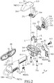
- the first embodiment of a saddle device is adapted to be mounted to a seat post 100, and includes a first seat unit 10 connected to a top portion of the seat post 100, a second seat unit 20, a saddle unit 30, a supporting member 40, a backrest 50, an adjusting unit 60 and a reinforcing frame member 70.
- the first seat unit 10 has a track portion 11 extending in a front-rear direction (X), and a front mounting portion 12 disposed in front of the track portion 11.
- the track portion 11 has a non-circular cross section taken perpendicular to the front-rear direction (X). In this embodiment, the track portion 11 has an 8-shaped cross section, and may be varied in other embodiments.
- the track portion 11 has a rear end surface 111, and two engaging holes 112 formed in the rear end surface 111, and extending in the front-rear direction (X) .
- the front mounting portion 12 has an engaging groove 121 formed in a top surface thereof.
- the second seat unit 20 is mounted to and disposed behind the first seat unit 10, and is movable on the track portion 11 of the first seat unit 10 in the front-rear direction (X).
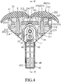
- the second seat unit 20 includes a main body 21, two bolts 22 extending through the main body 21, two toothed members 23 mounted to the main body 21, and a resilient positioning member 24 mounted to the main body 21.
- the main body 21 has an upper surface 211, a receiving groove 212 formed in the upper surface 211, and extending in a left-right direction which is perpendicular to the front-rear direction (X), and two positioning seats 213 fixedly disposed in the receiving groove 212.
- Each of the positioning seats 213 is formed with a through hole 214 extending along an axis (L) which is perpendicular to the front-rear direction (X).
- the bolts 22 respectively extend through the through holes 214 of the positioning seats 213.
- Each of the bolts 22 has a head portion 221 abutting against a bottom portion of the main body 21, and a threaded portion 222 extending through the corresponding through hole 214.
- Each of the toothed members 23 is mounted to the main body 21, is rotatable about a respective one of the axes (L) of the toothed members 23, and has an annular portion 231, an interacting portion 232 integrally connected to the annular portion 231, a lower crown gear portion 233 disposed at a top portion of the annular portion 231, and centered at a corresponding one of the axes (L), a plurality of finger-shaped teeth 234 formed on one end of the interacting portion 232 that is distal from the annular portion 231, and a plurality of positioning grooves 235 formed in one end of the interacting portion 232 that is distal from the annular portion 231, and disposed under the finger-shaped teeth 234.
- the finger-shaped teeth 234 of one of the toothed members 23 mesh with the finger-shaped teeth 234 of the other one of the toothed members 23 (see Figure 3 ), such that when the one of the toothed members 23 rotates in a direction, the other one of the toothed members 23 rotates in an opposite direction.
- the resilient positioning member 24 is inverted U-shaped, and has two lower ends abutting against the main body 21, and an engaging portion 241 biased to press against one of the toothed members 23, and engaging one of the positioning grooves 235 of the one of the toothed members 23.
- the engaging portion 241 protrudes upwardly from a middle portion of the resilient positioning member 24, and such configuration may be varied in other embodiments.
- the saddle unit 30 is mounted to the second seat unit 20, and includes two saddles 31 respectively corresponding to the toothed members 23 in position.
- Each of the saddles 31 has an upper end portion having a flat top surface 311, a lower end portion 312 opposite to the upper end portion, a rear end edge 313, a front end edge 314 opposite to the rear end edge 313, an upper crown gear portion 315 disposed at the lower end portion 312, and coaxial with the lower crown gear portion 233 of a corresponding one of the toothed members 23, and a rod segment 316 extending along the corresponding one of the axes (L), and rotatably extending through the annular portion 231 of the corresponding one of the toothed members 23.
- the flat top surfaces 311 of the saddles 31 cooperately form a top surface unit 32.
- Each of the rod segments 316 of the saddles 31 has a threaded hole 317.
- the upper crown gear portion 315 of each of the saddles 31 is disposed coaxially with a corresponding one of the threaded holes 317.
- the bolts 22 respectively and threadedly engage the threaded holes 317 of the saddles 31, so as to allow the lower crown gear portions 233 of the toothed members 23 to respectively engage the upper crown gear portions 315 of the saddles 31, thereby allowing the saddles 31 to respectively co-rotate with the toothed members 23, such that each of the bolts 22 is rotatable to allow for an adjustment to angular position of a corresponding one of the saddles 31 relative to a corresponding one of the toothed members 23.
- a distance between the front end edge 314 and the axis (L) is larger than a distance between the rear end edge 313 and the axis (L) .
- each of the saddles 31 meshes with the lower crown gear portion 233 of the corresponding one of the toothed members 23, such that each of the saddles 31 is rotatable relative to the corresponding one of the toothed members 23 about the corresponding one of the axes (L) of the toothed members 23 for adjusting a distance between the rear end edges 313 of the saddles 31 and a distance between the front end edges 314 of the saddles 31.
- the supporting member 40 is connected to the first seat unit 10, and has a coupling end 41, and a rear mounting end portion 42 opposite to the coupling end 41 and disposed behind the second seat unit 20, and distal from the first seat unit 10.
- the coupling end 41 has a coupling groove 411 corresponding to the cross section of the track portion 11 in shape, and engaged with the track portion 11, and a locking hole 412 communicated with the coupling groove 411.
- the supporting member 40 includes a screw 413 extending through the locking hole 412 and into the coupling groove 411 to threadedly engage one of the engaging holes 112 of the track portion 11.
- the rear mounting end portion 42 has two mounting holes 421 juxtaposed in a direction which is parallel to the axes (L), and two fastening holes 422 respectively communicated with the mounting holes 421.
- the shape of each of the mounting holes 421 is rectangular, and may be varied in other embodiments.
- the backrest 50 has a connecting block 51 having a backrest threaded hole 511.
- the adjusting unit 60 is mounted between the first seat unit 10 and the second seat unit 20, and includes a rack 61 extending in the front-rear direction (X), and mounted to the track portion 11 of the first seat unit 10, and a worm 62 mounted to the main body 21 of the second seat unit 20, and meshing with the rack 61 (see Figure 5 ).
- the worm 62 has a hexagonal hole 621 disposed for being engaged by a hex key wrench (not shown). The hex key wrench is operable to rotate the worm 62 to drive a relative movement between the first and second seat units 10, 20 in the front-rear direction (X).
- the reinforcing frame member 70 has a U-shaped rod part 71 adapted to be disposed around the seat post 100, and a connecting rod part 72 connected to the U-shaped rod part 71, and securely inserted into the first seat unit 10.
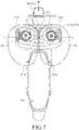
- the supporting member 40 is transformable between a lifted position (see Figure 6 ) and a lowered position (see Figure 1 ) such that, when the supporting member 40 is at the lifted position, the rear mounting end portion 42 is located above the top surface unit 32 of the saddle unit 30, and when the supporting member 40 is at the lowered position, the rear mounting end portion 42 is located below the top surface unit 32 of the saddle unit 30.
- the backrest 50 is mountable to the rear mounting end portion 42 when the supporting member 40 is at the lifted position, such that the backrest 50 is disposed behind the saddle unit 30, and is mountable to the front mounting portion 12 when the supporting member 40 is at the lowered position, such that the backrest 50 is disposed in front of the saddle unit 30.
- a screw extends through a corresponding one of the fastening holes 422, and threadedly engages the backrest threaded hole 511 to fasten the backrest 50 to the supporting member 40.
- the connecting block 51 engages the engaging groove 121 of the front mounting portion 12.
- a saddle bag 200 which is disposed for receiving repairing tools, repairing members and a wallet is fastened to the rear mounting end portion 42 by a screw (not shown) .
- the backrest 50 is fastened to the front mounting portion 12 by a screw, such that the backrest 50 is prevented from being removed from the front mounting portion 12. Therefore, the disposition of the backrest 50 not only increases the support to the saddle unit 30, but also reduces the space occupied when it is not used.
- the supporting member 40 When the supporting member 40 is required to transform from the lowered position to the lifted position, a user firstly needs to remove the saddle bag 200, then operates the screw 413 to remove the supporting member 40 from the track portion 11. The supporting member 40 is then flipped 180 degrees relative to the first seat unit 10, and is subsequently mounted back to the track portion 11. As shown in Figure 6 , at the lifted position, the backrest 50 can be mounted to the rear mounting end portion 42 for supporting the back of the user. Since the backrest 50 is fastened to the rear mounting end portion 42 by the screw, the backrest 50 is prevented from being removed from the supporting member 40.
- the user needs to rotate one of the saddles 31.
- the upper crown gear portion 315 of the one of the saddles 31 co-rotates with the lower crown gear portion 233 of the corresponding one of the toothed members 23, such that the corresponding one of the toothed members 23 is simultaneously rotated by the one of the saddles 31.
- the finger-shaped teeth 234 of the corresponding one of the toothed members 23 meshes with the finger-shaped teeth 234 of the other one of the toothed members 23, such that the other one of the saddles is driven to rotate in an opposite direction.
- the positioning grooves 235 rotate relative to the engaging portion 241 of the resilient positioning member 24, so that a clicking sound is generated until the saddles 31 stop to rotate. Since the engaging portion 241 engages the corresponding one of the positioning grooves 235, the positions of the toothed members 23 are fixed relative to the main body 21, and the saddles 31 are also positioned.
- the user may rotate the bolts 22 first so that, when one of the saddles 31 is rotated by the user, the one of the saddles 31 is rotated relative to a corresponding one of the toothed members 23, the angular position of the one of the saddles 31 relative to the corresponding one of the toothed members 23 is adjusted, and the distance between the rear end edges 313 of the saddles 31 and the distance between the front end edges 314 of the saddles 31 are also adjusted.
- the position of the supporting member 40, the position of the second seat unit 20 and the saddle unit 30 on the track portion 11, and the distance between the rear end edges 313 of the saddles 31 and the distance between the front end edges 314 of the saddles 31 are adjustable by the user to meet the operation requirements.
- the shape of the saddles 31 may be varied based on different physiological conditions in other embodiments.
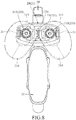
- the second embodiment of the saddle device according to the disclosure has a structure similar to that of the first embodiment.
- the main difference between this embodiment and the previous embodiment resides in the configuration of the second seat unit 20'.
- the second seat unit 20' includes a main body 21' having a receiving groove 212' that extends in the left-right direction which is perpendicular to the front-rear direction (X), two bolts 22' extending through the main body 21', and two toothed members 23' non-rotatably mounted to the main body 21' .
- Each of the toothed members 23' has an annular portion 231', two engaging blocks 232' connected to a bottom portion of the annular portion 231', and engaging the receiving groove 212' such that they cannot be rotated within the receiving grooves 212' , and a lower crown gear portion 233' disposed at a top portion of the annular portion 231' , and centered at an axis (L).
- the upper crown gear portions 315 of the saddles 31 respectively mesh with the lower crown gear portion 233' of the toothed members 23'.
- the corresponding bolt 22 When the user needs to adjust the angular position of one of the saddles 31, the corresponding bolt 22 is loosened such that it remains in the corresponding threaded hole 317 of the corresponding saddle 31, and the one of the saddles 31 is removed from and rotated relative to the corresponding toothed member 23 to adjust the angular position of the one of the saddles 31. After the adjustment is completed, the corresponding bolt 22 is tightened such that the corresponding upper and lower crown gears 315, 233' mesh with each other, thereby maintaining the angular position of the one of the saddles 31.
- the second embodiment has the same advantages as those of the first embodiment, and therefore the operation requirements also can be met.
Landscapes
- Engineering & Computer Science (AREA)
- Mechanical Engineering (AREA)
- Chairs For Special Purposes, Such As Reclining Chairs (AREA)
- Chair Legs, Seat Parts, And Backrests (AREA)
- Seats For Vehicles (AREA)
Applications Claiming Priority (1)
| Application Number | Priority Date | Filing Date | Title |
|---|---|---|---|
| TW106113092A TWI624393B (zh) | 2017-04-19 | 2017-04-19 | Seat cushion device |
Publications (2)
| Publication Number | Publication Date |
|---|---|
| EP3392126A1 true EP3392126A1 (fr) | 2018-10-24 |
| EP3392126B1 EP3392126B1 (fr) | 2019-08-28 |
Family
ID=59914407
Family Applications (1)
| Application Number | Title | Priority Date | Filing Date |
|---|---|---|---|
| EP17191980.6A Not-in-force EP3392126B1 (fr) | 2017-04-19 | 2017-09-19 | Dispositif de selle |
Country Status (4)
| Country | Link |
|---|---|
| US (1) | US10106217B1 (fr) |
| EP (1) | EP3392126B1 (fr) |
| CN (1) | CN107284563B (fr) |
| TW (1) | TWI624393B (fr) |
Families Citing this family (7)
| Publication number | Priority date | Publication date | Assignee | Title |
|---|---|---|---|---|
| TWI624394B (zh) * | 2017-04-19 | 2018-05-21 | Hsin Hsiang Hsu | 座墊裝置 |
| JP7142472B2 (ja) * | 2018-06-12 | 2022-09-27 | Juki株式会社 | クランプ治具及びクランプ補助装置 |
| US11052958B2 (en) * | 2018-10-02 | 2021-07-06 | Xsensor Technology Corporation | Bicycle seats |
| US11760431B2 (en) | 2018-10-02 | 2023-09-19 | Xsensor Technology Corporation | Bicycle seat for improved comfort, performance, and safety |
| US10988194B1 (en) * | 2019-10-02 | 2021-04-27 | Lewis Gluck | Bicycle saddle |
| US12552480B2 (en) * | 2020-01-10 | 2026-02-17 | James Colthurst | Ergonomically designed bicycle saddle |
| US12459590B2 (en) * | 2023-10-31 | 2025-11-04 | Foming Bicycle Parts Co., Ltd. | Bicycle seat capable of being adjustably moved |
Citations (5)
| Publication number | Priority date | Publication date | Assignee | Title |
|---|---|---|---|---|
| US694875A (en) | 1901-10-04 | 1902-03-04 | George A Meighan | Bicycle-saddle. |
| FR373620A (fr) * | 1907-01-16 | 1907-05-22 | Elie Mirovitch | Selle perfectionnée pour le cyclisme et autres usages analogues |
| FR954649A (fr) * | 1950-01-04 | |||
| FR1124175A (fr) * | 1955-03-29 | 1956-10-05 | Appui de selle pour cycle et motocycle | |
| CN2240480Y (zh) * | 1995-06-29 | 1996-11-20 | 李克俭 | 健身式逍遥型靠背自行车 |
Family Cites Families (32)
| Publication number | Priority date | Publication date | Assignee | Title |
|---|---|---|---|---|
| US616178A (en) * | 1898-12-20 | George f | ||
| US608682A (en) * | 1898-08-09 | Cycle-saddle | ||
| US629956A (en) * | 1897-03-06 | 1899-08-01 | Warren H Craig | Bicycle-saddle. |
| US3243231A (en) * | 1964-09-01 | 1966-03-29 | Ethel Benedict | Saddle for bicycles |
| US4063775A (en) * | 1975-10-02 | 1977-12-20 | Mesinger Robert H | Unitary cycle seat support unit |
| US4512608A (en) * | 1982-04-05 | 1985-04-23 | Erani Homi K | Saddle assembly |
| US4541668A (en) * | 1984-06-08 | 1985-09-17 | William Rouw | Cycle seat |
| CH681879A5 (fr) * | 1990-06-06 | 1993-06-15 | Michele Chiarella | |
| AUPN350595A0 (en) * | 1995-06-14 | 1995-07-06 | Nelson, Paul Damian | A seat |
| DE19734742A1 (de) * | 1997-08-12 | 1999-02-18 | Steffen Heintz | Ergo-Sattel |
| US6068333A (en) * | 1999-08-06 | 2000-05-30 | Dixon; Jeffrey | Dual support unit bicycle seat |
| US6290291B1 (en) * | 2000-10-27 | 2001-09-18 | Shimano Inc. | Adjustable bicycle saddle |
| US6554355B2 (en) * | 2000-12-05 | 2003-04-29 | Robert Kaptur | Anatomical bicycle seat |
| TW573653U (en) * | 2002-01-19 | 2004-01-21 | Velo Entpr Co Ltd | Bicycle seat cushion with adjustment function |
| CN2523668Y (zh) * | 2002-03-01 | 2002-12-04 | 维乐工业有限公司 | 具有调整功能的自行车座垫 |
| US7178869B2 (en) * | 2005-05-12 | 2007-02-20 | Paul Ljubich | Bicycle seat |
| CN2846276Y (zh) * | 2005-11-16 | 2006-12-13 | 叶明永 | 具有靠背和充气装置的自行车 |
| US8047604B2 (en) * | 2005-11-17 | 2011-11-01 | Louis Chuang | Bicycle saddle |
| TWI275509B (en) * | 2005-11-25 | 2007-03-11 | Topeak Inc | Bicycle's seat capable of adjustment size |
| ITMI20061404A1 (it) * | 2006-07-19 | 2008-01-20 | Selle Italia Srl | Struttura di sella regolabile,particolarmente per biciclette |
| US7494181B2 (en) * | 2006-09-05 | 2009-02-24 | Samuel Tucker | Bicycle seat |
| US7581787B2 (en) * | 2007-06-17 | 2009-09-01 | Ino Vision Ltd. | Bicycle seat lock |
| GB201016319D0 (en) * | 2010-09-29 | 2010-11-10 | Onyeka George C | Retractable nose saddle |
| US20120086246A1 (en) * | 2010-10-07 | 2012-04-12 | Armand Belliveau | Twin-pad bicycle seat for long distance cycling |
| TWM444971U (zh) * | 2012-07-27 | 2013-01-11 | Jyun-Hong Lin | 可拆換與自鎖式自行車坐墊裝置 |
| CN104002895B (zh) * | 2013-02-25 | 2016-07-20 | 欧亚马自行车(太仓)有限公司 | 可调式的自行车坐垫 |
| US9493203B2 (en) * | 2014-03-04 | 2016-11-15 | Lyle Portz | Bicycle seat |
| TW201536613A (zh) * | 2014-03-21 | 2015-10-01 | Univ Nat Pingtung Sci & Tech | 多功能自行車坐墊 |
| US9663166B2 (en) * | 2014-09-05 | 2017-05-30 | Michael Raymond HAMEL | Bicycle seat with adjustable nose |
| TWM513821U (zh) * | 2015-06-02 | 2015-12-11 | Wen-Yu Liu | 腳踏車座墊結構 |
| CN205075972U (zh) * | 2015-11-03 | 2016-03-09 | 娄奥 | 可调骑行姿势的新型骑行车 |
| US9821867B2 (en) * | 2016-02-11 | 2017-11-21 | Jared S. Goff | Bicycle seat |
-
2017
- 2017-04-19 TW TW106113092A patent/TWI624393B/zh not_active IP Right Cessation
- 2017-06-29 CN CN201710516083.3A patent/CN107284563B/zh active Active
- 2017-08-25 US US15/686,806 patent/US10106217B1/en not_active Expired - Fee Related
- 2017-09-19 EP EP17191980.6A patent/EP3392126B1/fr not_active Not-in-force
Patent Citations (5)
| Publication number | Priority date | Publication date | Assignee | Title |
|---|---|---|---|---|
| FR954649A (fr) * | 1950-01-04 | |||
| US694875A (en) | 1901-10-04 | 1902-03-04 | George A Meighan | Bicycle-saddle. |
| FR373620A (fr) * | 1907-01-16 | 1907-05-22 | Elie Mirovitch | Selle perfectionnée pour le cyclisme et autres usages analogues |
| FR1124175A (fr) * | 1955-03-29 | 1956-10-05 | Appui de selle pour cycle et motocycle | |
| CN2240480Y (zh) * | 1995-06-29 | 1996-11-20 | 李克俭 | 健身式逍遥型靠背自行车 |
Also Published As
| Publication number | Publication date |
|---|---|
| CN107284563A (zh) | 2017-10-24 |
| CN107284563B (zh) | 2019-06-11 |
| US10106217B1 (en) | 2018-10-23 |
| US20180304947A1 (en) | 2018-10-25 |
| EP3392126B1 (fr) | 2019-08-28 |
| TWI624393B (zh) | 2018-05-21 |
| TW201838851A (zh) | 2018-11-01 |
Similar Documents
| Publication | Publication Date | Title |
|---|---|---|
| EP3392126B1 (fr) | Dispositif de selle | |
| EP3392127B1 (fr) | Dispositif de selle | |
| CN101815644B (zh) | 用于自行车车座的角度调整装置 | |
| US4652053A (en) | Seat belt apparatus for a vehicle seat | |
| DE102008064057B4 (de) | Fahrradkettenumwerfer mit mehreren Montageeinstellungen | |
| CN201437389U (zh) | 双向可调式机车后视镜 | |
| CA2108645A1 (fr) | Dispositif de reglage de lame de scie | |
| US20090218857A1 (en) | Device for Adjusting the Angle of Inclination of a Saddle | |
| CN109017463B (zh) | 一种适用于座椅的可调靠肩 | |
| CN205668610U (zh) | 可调节角度的摩托车乘员靠背装置 | |
| US2966938A (en) | Seat divider and rest | |
| CN212455390U (zh) | 一种赛车用链条张紧机构 | |
| US6767053B1 (en) | All terrain vehicle back support | |
| CN210178109U (zh) | 一种具有间隙补偿功能的执手机构 | |
| DE112015005837T5 (de) | Antrieb eines Räderfahrzeugs, insbesondere eines Fahrrads | |
| CN209629297U (zh) | 高度可调枕头 | |
| CN207984641U (zh) | 一种汽车座椅靠背腰托控制装置 | |
| CN223658307U (zh) | 一种人体工学自行车坐垫调节机构 | |
| DE202010009225U1 (de) | Verstellbare Soziushaltevorrichtung | |
| CN208359983U (zh) | 一种汽车座椅靠背腰托调节装置 | |
| JP5159202B2 (ja) | トラクタのアシストグリップ | |
| CN222179163U (zh) | 一种汽车遮阳板固定座结构 | |
| CN215094782U (zh) | 建筑专业用砖块切割装置 | |
| AU598682B2 (en) | Seat adjustment mechanism | |
| DE4039723A1 (de) | Fahrrad- und gepaeckhalter fuer die heckklappe bei fahrzeugen |
Legal Events
| Date | Code | Title | Description |
|---|---|---|---|
| PUAI | Public reference made under article 153(3) epc to a published international application that has entered the european phase |
Free format text: ORIGINAL CODE: 0009012 |
|
| STAA | Information on the status of an ep patent application or granted ep patent |
Free format text: STATUS: THE APPLICATION HAS BEEN PUBLISHED |
|
| STAA | Information on the status of an ep patent application or granted ep patent |
Free format text: STATUS: REQUEST FOR EXAMINATION WAS MADE |
|
| AK | Designated contracting states |
Kind code of ref document: A1 Designated state(s): AL AT BE BG CH CY CZ DE DK EE ES FI FR GB GR HR HU IE IS IT LI LT LU LV MC MK MT NL NO PL PT RO RS SE SI SK SM TR |
|
| AX | Request for extension of the european patent |
Extension state: BA ME |
|
| 17P | Request for examination filed |
Effective date: 20181008 |
|
| RBV | Designated contracting states (corrected) |
Designated state(s): AL AT BE BG CH CY CZ DE DK EE ES FI FR GB GR HR HU IE IS IT LI LT LU LV MC MK MT NL NO PL PT RO RS SE SI SK SM TR |
|
| GRAP | Despatch of communication of intention to grant a patent |
Free format text: ORIGINAL CODE: EPIDOSNIGR1 |
|
| STAA | Information on the status of an ep patent application or granted ep patent |
Free format text: STATUS: GRANT OF PATENT IS INTENDED |
|
| RIC1 | Information provided on ipc code assigned before grant |
Ipc: B62J 1/08 20060101AFI20190227BHEP Ipc: B62J 1/28 20060101ALI20190227BHEP Ipc: B62J 1/20 20060101ALI20190227BHEP Ipc: B62J 1/14 20060101ALI20190227BHEP Ipc: B62J 1/00 20060101ALI20190227BHEP |
|
| INTG | Intention to grant announced |
Effective date: 20190312 |
|
| GRAS | Grant fee paid |
Free format text: ORIGINAL CODE: EPIDOSNIGR3 |
|
| GRAA | (expected) grant |
Free format text: ORIGINAL CODE: 0009210 |
|
| STAA | Information on the status of an ep patent application or granted ep patent |
Free format text: STATUS: THE PATENT HAS BEEN GRANTED |
|
| AK | Designated contracting states |
Kind code of ref document: B1 Designated state(s): AL AT BE BG CH CY CZ DE DK EE ES FI FR GB GR HR HU IE IS IT LI LT LU LV MC MK MT NL NO PL PT RO RS SE SI SK SM TR |
|
| REG | Reference to a national code |
Ref country code: GB Ref legal event code: FG4D |
|
| REG | Reference to a national code |
Ref country code: CH Ref legal event code: EP |
|
| REG | Reference to a national code |
Ref country code: DE Ref legal event code: R096 Ref document number: 602017006502 Country of ref document: DE |
|
| REG | Reference to a national code |
Ref country code: AT Ref legal event code: REF Ref document number: 1172053 Country of ref document: AT Kind code of ref document: T Effective date: 20190915 |
|
| REG | Reference to a national code |
Ref country code: IE Ref legal event code: FG4D |
|
| PGFP | Annual fee paid to national office [announced via postgrant information from national office to epo] |
Ref country code: DE Payment date: 20190827 Year of fee payment: 3 |
|
| REG | Reference to a national code |
Ref country code: NL Ref legal event code: MP Effective date: 20190828 |
|
| REG | Reference to a national code |
Ref country code: LT Ref legal event code: MG4D |
|
| PG25 | Lapsed in a contracting state [announced via postgrant information from national office to epo] |
Ref country code: NO Free format text: LAPSE BECAUSE OF FAILURE TO SUBMIT A TRANSLATION OF THE DESCRIPTION OR TO PAY THE FEE WITHIN THE PRESCRIBED TIME-LIMIT Effective date: 20191128 Ref country code: HR Free format text: LAPSE BECAUSE OF FAILURE TO SUBMIT A TRANSLATION OF THE DESCRIPTION OR TO PAY THE FEE WITHIN THE PRESCRIBED TIME-LIMIT Effective date: 20190828 Ref country code: SE Free format text: LAPSE BECAUSE OF FAILURE TO SUBMIT A TRANSLATION OF THE DESCRIPTION OR TO PAY THE FEE WITHIN THE PRESCRIBED TIME-LIMIT Effective date: 20190828 Ref country code: FI Free format text: LAPSE BECAUSE OF FAILURE TO SUBMIT A TRANSLATION OF THE DESCRIPTION OR TO PAY THE FEE WITHIN THE PRESCRIBED TIME-LIMIT Effective date: 20190828 Ref country code: PT Free format text: LAPSE BECAUSE OF FAILURE TO SUBMIT A TRANSLATION OF THE DESCRIPTION OR TO PAY THE FEE WITHIN THE PRESCRIBED TIME-LIMIT Effective date: 20191230 Ref country code: LT Free format text: LAPSE BECAUSE OF FAILURE TO SUBMIT A TRANSLATION OF THE DESCRIPTION OR TO PAY THE FEE WITHIN THE PRESCRIBED TIME-LIMIT Effective date: 20190828 Ref country code: NL Free format text: LAPSE BECAUSE OF FAILURE TO SUBMIT A TRANSLATION OF THE DESCRIPTION OR TO PAY THE FEE WITHIN THE PRESCRIBED TIME-LIMIT Effective date: 20190828 Ref country code: BG Free format text: LAPSE BECAUSE OF FAILURE TO SUBMIT A TRANSLATION OF THE DESCRIPTION OR TO PAY THE FEE WITHIN THE PRESCRIBED TIME-LIMIT Effective date: 20191128 |
|
| PG25 | Lapsed in a contracting state [announced via postgrant information from national office to epo] |
Ref country code: ES Free format text: LAPSE BECAUSE OF FAILURE TO SUBMIT A TRANSLATION OF THE DESCRIPTION OR TO PAY THE FEE WITHIN THE PRESCRIBED TIME-LIMIT Effective date: 20190828 Ref country code: AL Free format text: LAPSE BECAUSE OF FAILURE TO SUBMIT A TRANSLATION OF THE DESCRIPTION OR TO PAY THE FEE WITHIN THE PRESCRIBED TIME-LIMIT Effective date: 20190828 Ref country code: LV Free format text: LAPSE BECAUSE OF FAILURE TO SUBMIT A TRANSLATION OF THE DESCRIPTION OR TO PAY THE FEE WITHIN THE PRESCRIBED TIME-LIMIT Effective date: 20190828 Ref country code: RS Free format text: LAPSE BECAUSE OF FAILURE TO SUBMIT A TRANSLATION OF THE DESCRIPTION OR TO PAY THE FEE WITHIN THE PRESCRIBED TIME-LIMIT Effective date: 20190828 Ref country code: IS Free format text: LAPSE BECAUSE OF FAILURE TO SUBMIT A TRANSLATION OF THE DESCRIPTION OR TO PAY THE FEE WITHIN THE PRESCRIBED TIME-LIMIT Effective date: 20191228 Ref country code: GR Free format text: LAPSE BECAUSE OF FAILURE TO SUBMIT A TRANSLATION OF THE DESCRIPTION OR TO PAY THE FEE WITHIN THE PRESCRIBED TIME-LIMIT Effective date: 20191129 |
|
| REG | Reference to a national code |
Ref country code: AT Ref legal event code: MK05 Ref document number: 1172053 Country of ref document: AT Kind code of ref document: T Effective date: 20190828 |
|
| PG25 | Lapsed in a contracting state [announced via postgrant information from national office to epo] |
Ref country code: TR Free format text: LAPSE BECAUSE OF FAILURE TO SUBMIT A TRANSLATION OF THE DESCRIPTION OR TO PAY THE FEE WITHIN THE PRESCRIBED TIME-LIMIT Effective date: 20190828 |
|
| PG25 | Lapsed in a contracting state [announced via postgrant information from national office to epo] |
Ref country code: IT Free format text: LAPSE BECAUSE OF FAILURE TO SUBMIT A TRANSLATION OF THE DESCRIPTION OR TO PAY THE FEE WITHIN THE PRESCRIBED TIME-LIMIT Effective date: 20190828 Ref country code: RO Free format text: LAPSE BECAUSE OF FAILURE TO SUBMIT A TRANSLATION OF THE DESCRIPTION OR TO PAY THE FEE WITHIN THE PRESCRIBED TIME-LIMIT Effective date: 20190828 Ref country code: PL Free format text: LAPSE BECAUSE OF FAILURE TO SUBMIT A TRANSLATION OF THE DESCRIPTION OR TO PAY THE FEE WITHIN THE PRESCRIBED TIME-LIMIT Effective date: 20190828 Ref country code: EE Free format text: LAPSE BECAUSE OF FAILURE TO SUBMIT A TRANSLATION OF THE DESCRIPTION OR TO PAY THE FEE WITHIN THE PRESCRIBED TIME-LIMIT Effective date: 20190828 Ref country code: AT Free format text: LAPSE BECAUSE OF FAILURE TO SUBMIT A TRANSLATION OF THE DESCRIPTION OR TO PAY THE FEE WITHIN THE PRESCRIBED TIME-LIMIT Effective date: 20190828 Ref country code: DK Free format text: LAPSE BECAUSE OF FAILURE TO SUBMIT A TRANSLATION OF THE DESCRIPTION OR TO PAY THE FEE WITHIN THE PRESCRIBED TIME-LIMIT Effective date: 20190828 |
|
| PG25 | Lapsed in a contracting state [announced via postgrant information from national office to epo] |
Ref country code: MC Free format text: LAPSE BECAUSE OF FAILURE TO SUBMIT A TRANSLATION OF THE DESCRIPTION OR TO PAY THE FEE WITHIN THE PRESCRIBED TIME-LIMIT Effective date: 20190828 Ref country code: IS Free format text: LAPSE BECAUSE OF FAILURE TO SUBMIT A TRANSLATION OF THE DESCRIPTION OR TO PAY THE FEE WITHIN THE PRESCRIBED TIME-LIMIT Effective date: 20200224 Ref country code: SM Free format text: LAPSE BECAUSE OF FAILURE TO SUBMIT A TRANSLATION OF THE DESCRIPTION OR TO PAY THE FEE WITHIN THE PRESCRIBED TIME-LIMIT Effective date: 20190828 Ref country code: SK Free format text: LAPSE BECAUSE OF FAILURE TO SUBMIT A TRANSLATION OF THE DESCRIPTION OR TO PAY THE FEE WITHIN THE PRESCRIBED TIME-LIMIT Effective date: 20190828 Ref country code: CZ Free format text: LAPSE BECAUSE OF FAILURE TO SUBMIT A TRANSLATION OF THE DESCRIPTION OR TO PAY THE FEE WITHIN THE PRESCRIBED TIME-LIMIT Effective date: 20190828 |
|
| REG | Reference to a national code |
Ref country code: DE Ref legal event code: R097 Ref document number: 602017006502 Country of ref document: DE |
|
| PLBE | No opposition filed within time limit |
Free format text: ORIGINAL CODE: 0009261 |
|
| STAA | Information on the status of an ep patent application or granted ep patent |
Free format text: STATUS: NO OPPOSITION FILED WITHIN TIME LIMIT |
|
| PG2D | Information on lapse in contracting state deleted |
Ref country code: IS |
|
| PG25 | Lapsed in a contracting state [announced via postgrant information from national office to epo] |
Ref country code: IE Free format text: LAPSE BECAUSE OF NON-PAYMENT OF DUE FEES Effective date: 20190919 Ref country code: LU Free format text: LAPSE BECAUSE OF NON-PAYMENT OF DUE FEES Effective date: 20190919 |
|
| 26N | No opposition filed |
Effective date: 20200603 |
|
| REG | Reference to a national code |
Ref country code: BE Ref legal event code: MM Effective date: 20190930 |
|
| PG25 | Lapsed in a contracting state [announced via postgrant information from national office to epo] |
Ref country code: BE Free format text: LAPSE BECAUSE OF NON-PAYMENT OF DUE FEES Effective date: 20190930 |
|
| PG25 | Lapsed in a contracting state [announced via postgrant information from national office to epo] |
Ref country code: FR Free format text: LAPSE BECAUSE OF NON-PAYMENT OF DUE FEES Effective date: 20191028 |
|
| REG | Reference to a national code |
Ref country code: DE Ref legal event code: R119 Ref document number: 602017006502 Country of ref document: DE |
|
| REG | Reference to a national code |
Ref country code: CH Ref legal event code: PL |
|
| PG25 | Lapsed in a contracting state [announced via postgrant information from national office to epo] |
Ref country code: CY Free format text: LAPSE BECAUSE OF FAILURE TO SUBMIT A TRANSLATION OF THE DESCRIPTION OR TO PAY THE FEE WITHIN THE PRESCRIBED TIME-LIMIT Effective date: 20190828 |
|
| PG25 | Lapsed in a contracting state [announced via postgrant information from national office to epo] |
Ref country code: HU Free format text: LAPSE BECAUSE OF FAILURE TO SUBMIT A TRANSLATION OF THE DESCRIPTION OR TO PAY THE FEE WITHIN THE PRESCRIBED TIME-LIMIT; INVALID AB INITIO Effective date: 20170919 Ref country code: MT Free format text: LAPSE BECAUSE OF FAILURE TO SUBMIT A TRANSLATION OF THE DESCRIPTION OR TO PAY THE FEE WITHIN THE PRESCRIBED TIME-LIMIT Effective date: 20190828 Ref country code: DE Free format text: LAPSE BECAUSE OF NON-PAYMENT OF DUE FEES Effective date: 20210401 |
|
| PG25 | Lapsed in a contracting state [announced via postgrant information from national office to epo] |
Ref country code: CH Free format text: LAPSE BECAUSE OF NON-PAYMENT OF DUE FEES Effective date: 20200930 Ref country code: LI Free format text: LAPSE BECAUSE OF NON-PAYMENT OF DUE FEES Effective date: 20200930 |
|
| PG25 | Lapsed in a contracting state [announced via postgrant information from national office to epo] |
Ref country code: SI Free format text: LAPSE BECAUSE OF FAILURE TO SUBMIT A TRANSLATION OF THE DESCRIPTION OR TO PAY THE FEE WITHIN THE PRESCRIBED TIME-LIMIT Effective date: 20190828 |
|
| GBPC | Gb: european patent ceased through non-payment of renewal fee |
Effective date: 20210919 |
|
| PG25 | Lapsed in a contracting state [announced via postgrant information from national office to epo] |
Ref country code: MK Free format text: LAPSE BECAUSE OF FAILURE TO SUBMIT A TRANSLATION OF THE DESCRIPTION OR TO PAY THE FEE WITHIN THE PRESCRIBED TIME-LIMIT Effective date: 20190828 |
|
| PG25 | Lapsed in a contracting state [announced via postgrant information from national office to epo] |
Ref country code: GB Free format text: LAPSE BECAUSE OF NON-PAYMENT OF DUE FEES Effective date: 20210919 |