EP3392140B1 - Notfeststellbremssystem - Google Patents
Notfeststellbremssystem Download PDFInfo
- Publication number
- EP3392140B1 EP3392140B1 EP18168036.4A EP18168036A EP3392140B1 EP 3392140 B1 EP3392140 B1 EP 3392140B1 EP 18168036 A EP18168036 A EP 18168036A EP 3392140 B1 EP3392140 B1 EP 3392140B1
- Authority
- EP
- European Patent Office
- Prior art keywords
- park brake
- emergency park
- input interface
- user input
- status
- Prior art date
- Legal status (The legal status is an assumption and is not a legal conclusion. Google has not performed a legal analysis and makes no representation as to the accuracy of the status listed.)
- Active
Links
Images

Classifications
-
- B—PERFORMING OPERATIONS; TRANSPORTING
- B60—VEHICLES IN GENERAL
- B60T—VEHICLE BRAKE CONTROL SYSTEMS OR PARTS THEREOF; BRAKE CONTROL SYSTEMS OR PARTS THEREOF, IN GENERAL; ARRANGEMENT OF BRAKING ELEMENTS ON VEHICLES IN GENERAL; PORTABLE DEVICES FOR PREVENTING UNWANTED MOVEMENT OF VEHICLES; VEHICLE MODIFICATIONS TO FACILITATE COOLING OF BRAKES
- B60T8/00—Arrangements for adjusting wheel-braking force to meet varying vehicular or ground-surface conditions, e.g. limiting or varying distribution of braking force
- B60T8/17—Using electrical or electronic regulation means to control braking
- B60T8/1701—Braking or traction control means specially adapted for particular types of vehicles
- B60T8/1703—Braking or traction control means specially adapted for particular types of vehicles for aircrafts
-
- B—PERFORMING OPERATIONS; TRANSPORTING
- B60—VEHICLES IN GENERAL
- B60T—VEHICLE BRAKE CONTROL SYSTEMS OR PARTS THEREOF; BRAKE CONTROL SYSTEMS OR PARTS THEREOF, IN GENERAL; ARRANGEMENT OF BRAKING ELEMENTS ON VEHICLES IN GENERAL; PORTABLE DEVICES FOR PREVENTING UNWANTED MOVEMENT OF VEHICLES; VEHICLE MODIFICATIONS TO FACILITATE COOLING OF BRAKES
- B60T13/00—Transmitting braking action from initiating means to ultimate brake actuator with power assistance or drive; Brake systems incorporating such transmitting means, e.g. air-pressure brake systems
- B60T13/74—Transmitting braking action from initiating means to ultimate brake actuator with power assistance or drive; Brake systems incorporating such transmitting means, e.g. air-pressure brake systems with electrical assistance or drive
- B60T13/741—Transmitting braking action from initiating means to ultimate brake actuator with power assistance or drive; Brake systems incorporating such transmitting means, e.g. air-pressure brake systems with electrical assistance or drive acting on an ultimate actuator
-
- B—PERFORMING OPERATIONS; TRANSPORTING
- B60—VEHICLES IN GENERAL
- B60T—VEHICLE BRAKE CONTROL SYSTEMS OR PARTS THEREOF; BRAKE CONTROL SYSTEMS OR PARTS THEREOF, IN GENERAL; ARRANGEMENT OF BRAKING ELEMENTS ON VEHICLES IN GENERAL; PORTABLE DEVICES FOR PREVENTING UNWANTED MOVEMENT OF VEHICLES; VEHICLE MODIFICATIONS TO FACILITATE COOLING OF BRAKES
- B60T17/00—Component parts, details, or accessories of power brake systems not covered by groups B60T8/00, B60T13/00 or B60T15/00, or presenting other characteristic features
- B60T17/18—Safety devices; Monitoring
- B60T17/22—Devices for monitoring or checking brake systems; Signal devices
- B60T17/221—Procedure or apparatus for checking or keeping in a correct functioning condition of brake systems
-
- B—PERFORMING OPERATIONS; TRANSPORTING
- B64—AIRCRAFT; AVIATION; COSMONAUTICS
- B64C—AEROPLANES; HELICOPTERS
- B64C25/00—Alighting gear
- B64C25/32—Alighting gear characterised by elements which contact the ground or similar surface
- B64C25/42—Arrangement or adaptation of brakes
- B64C25/44—Actuating mechanisms
-
- B—PERFORMING OPERATIONS; TRANSPORTING
- B60—VEHICLES IN GENERAL
- B60T—VEHICLE BRAKE CONTROL SYSTEMS OR PARTS THEREOF; BRAKE CONTROL SYSTEMS OR PARTS THEREOF, IN GENERAL; ARRANGEMENT OF BRAKING ELEMENTS ON VEHICLES IN GENERAL; PORTABLE DEVICES FOR PREVENTING UNWANTED MOVEMENT OF VEHICLES; VEHICLE MODIFICATIONS TO FACILITATE COOLING OF BRAKES
- B60T2270/00—Further aspects of brake control systems not otherwise provided for
- B60T2270/40—Failsafe aspects of brake control systems
- B60T2270/413—Plausibility monitoring, cross check, redundancy
Definitions
- the present disclosure relates to aircraft systems, and more specifically, to emergency park brake systems.
- Aircraft typically have brakes on the wheels to slow the aircraft during aborted takeoffs, landings, and/or while taxiing. Additionally, some aircraft employ emergency park brake systems that execute emergency braking and/or maintain a braking force while the aircraft is parked.
- Conventional brake systems generally include a mechanical linkage (e.g., a cable) that extends between a user brake interface (e.g., a pedal or a handle) and a braking force actuator.
- a mechanical linkage e.g., a cable
- a user brake interface e.g., a pedal or a handle
- a braking force actuator e.g., a braking force actuator.
- the present disclosure provides an emergency park brake system of an aircraft as defined by claim 1.
- the operations in response to the emergency park brake condition indicating the failure condition, include displaying an indicator on a display device of the failure condition.
- the threshold difference is about 5%. In various embodiments, the threshold difference is about 3%.
- the emergency park brake condition is a first emergency park brake condition, wherein the operations further include determining, by the processor and based on the first status of the user input interface and the second status of the user input interface, a second emergency park brake condition.
- determining the second emergency park brake condition is based on the first emergency park brake condition. For example, determining the second emergency park brake condition may be performed in response to the first emergency park brake condition indicating an operative condition. In various embodiments, determining the second emergency park brake condition includes comparing a displacement of the user input interface, indicated by the first status of the user input interface and the second status of the user input interface, with a threshold displacement. In various embodiments, the operations further include determining whether the displacement of the user input interface is greater than the threshold displacement. In various embodiments, the second emergency park brake condition indicates a null demand in response to the displacement of the user input interface being less than the threshold displacement. In various embodiments, the second emergency park brake condition indicates a braking demand in response to the displacement of the user input interface being greater than the threshold displacement. In various embodiments, the threshold displacement is about 20% from a zero position to a maximum displacement position.
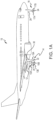
- an aircraft 10 may include landing gear such as main landing gear 12, main landing gear 14 and nose landing gear 16.
- Main landing gear 12, main landing gear 14, and nose landing gear 16 may generally support aircraft 10 when aircraft 10 is not flying, allowing aircraft 10 to taxi, take off and land without damage.
- Main landing gear 12 may include wheel 13A and wheel 13B coupled by an axle 20.
- Main landing gear 14 may include wheel 15A and wheel 15B coupled by an axle 22 and may be located proximate the wings 30 of the aircraft 10.
- Nose landing gear 16 may be located at the nose 28 of the aircraft 10 and may include nose wheel 17A and nose wheel 17B coupled by an axle 24.
- aircraft 10 may comprise any number of landing gears and each landing gear may comprise any number of wheels.
- Main landing gear 12, main landing gear 14, and nose landing gear 16 may each be retracted for flight.
- Aircraft 10 may also include a primary brake system, which may be applied to a wheel of a landing gear.
- the primary brake system of aircraft 10 may comprise a collection of subsystems that produce output signals for controlling the braking force and/or torque applied at each wheel (e.g., wheel 13A, wheel 13B, wheel 15A, wheel 15B, etc. wheel 17A, and/or wheel 17B).
- the primary brake system may communicate with the brakes of each landing gear (e.g., main landing gear 12, main landing gear 14, and/or nose landing gear 16), and each brake may be mounted to each wheel to apply and release braking force on one or more wheels (e.g., as described above).
- the brakes of an aircraft 10 may include a non-rotatable wheel support, a wheel (e.g., wheel 13A, wheel 13B, wheel 15A, wheel 15B, wheel 17A, and/or wheel 17B) mounted to the wheel support for rotation, and a brake disk stack.
- a wheel e.g., wheel 13A, wheel 13B, wheel 15A, wheel 15B, wheel 17A, and/or wheel 17B mounted to the wheel support for rotation
- a brake disk stack e.g., a brake disk stack.
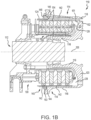
- brake assembly 110 may be found on an aircraft, in accordance with various embodiments.
- Brake assembly 110 may, for example, comprise a bogie axle 112, a wheel 114 including a hub 116 and a wheel well 118, a web 120, a torque take-out assembly 122, one or more torque bars 124, a wheel rotational axis 126, a wheel well recess 128, an actuator 130, multiple brake rotors 32, multiple brake stators 34, a pressure plate 36, an end plate 38, a heat shield 140, multiple heat shield sections 142, multiple heat shield carriers 144, an air gap 146, multiple torque bar bolts 148, a torque bar pin 151, a wheel web hole 152, multiple heat shield fasteners 153, multiple rotor lugs 154, and multiple stator slots 156.
- Brake disks e.g., interleaved rotors 32 and stators 34
- Rotors 32 are secured to torque bars 124 for rotation with wheel 114, while stators 34 are engaged with torque take-out assembly 122.
- At least one actuator 130 is operable to compress interleaved rotors 32 and stators 34 for stopping the aircraft.
- actuator 130 is shown as a hydraulically actuated piston.
- Pressure plate 36 and end plate 38 are disposed at opposite ends of the interleaved rotors 32 and stators 34.
- Rotors 32 and stators 34 can comprise any material suitable for friction disks, including ceramics or carbon materials, such as a carbon/carbon composite.
- Torque take-out assembly 122 is secured to a stationary portion of the landing gear truck such as a bogie beam or other landing gear strut, such that torque take-out assembly 122 and stators 34 are prevented from rotating during braking of the aircraft.
- aircraft 10 may also include one or more emergency park brake systems 200.
- the emergency park brake systems 200 includes a user input interface 205, a first displacement sensor 210, a second displacement sensor 212, an emergency park brake controller 220, and may further comprise a brake assembly 230 (which may be similar to brake assembly 110), and a wheel 213.
- the emergency park brake system 200 generally controls an emergency or parking braking force/torque that is applied and implemented via the brake assembly 230 to each wheel 213, according to various embodiments.
- the emergency park brake system 200 may be separate from, for example, a primary brake system.
- the brake assembly 230 may be shared with a primary brake system (as described in greater detail below) while the remaining components 205, 210, 212, 220 of the emergency park brake system 200 are not shared with the primary brake system and are thus unique to the emergency park brake system 200.
- the brake assembly 230 may employ fluid powered (hydraulic or pneumatic power) actuator rams or electromechanical actuator arms.
- the brake assembly 230 may be a hydraulic assembly and thus may be coupled to a power source via a brake servo valve (BSV) and a shutoff valve (SOV).
- BSV brake servo valve
- SOV shutoff valve
- the SOV may effectively function as a shutoff valve such that in response to the valve being in the first position (e.g., an armed position), fluid pressure is permitted to pass through the valve while in response to the valve being in a second position (e.g., a disarmed position), fluid pressure is restricted or prevented from passing through the valve.
- the brake assembly 230 is electric and includes an electromechanical actuator controller (EMAC) to control braking.
- EMC electromechanical actuator controller
- the brake system 200 receives user actuation input via the user input interface 205, as detected by the first displacement sensor 210 and the second displacement sensor 212, and the emergency park brake controller 220 controls the amount of fluid pressure or electromechanical force provided to the actuator ram, thus applying a braking force to the wheel 213.
- the emergency park brake controller 220 is generally configured to receive input from the first displacement sensor 210 and the second displacement sensor 212, as described in greater detail below, and translate the input into a command to be sent to the brake assembly 230, according to various embodiments.
- the emergency park brake controller 220 may be integrated into computer systems onboard aircraft 10 such as, for example, a brake control unit (BCU), a full authority digital engine control (FADEC), an engine-indicating and crew-alerting system (EICAS), and/or the like.
- the emergency park brake controller 220 may also be a standalone computer system separate from aircraft 10 and in electronic communication with aircraft 10, as described in further detail herein.
- the emergency park brake controller 220 may include one or more processors and/or one or more tangible, non-transitory memories and be capable of implementing logic.
- Each processor can be a general purpose processor, a digital signal processor (DSP), an application specific integrated circuit (ASIC), a field programmable gate array (FPGA) or other programmable logic device, discrete gate or transistor logic, discrete hardware components, or any combination thereof.
- DSP digital signal processor
- ASIC application specific integrated circuit
- FPGA field programmable gate array
- the processor of the emergency park brake controller 220 may be configured to implement various logical operations in response to execution of instructions, for example, instructions stored on the non-transitory memory (e.g., tangible, computer-readable medium).
- the term "non-transitory” is to be understood to remove only propagating transitory signals per se from the claim scope and does not relinquish rights to all standard computer-readable media that are not only propagating transitory signals per se.
- the one or more user input interfaces 205 of the emergency park brake system 200 are configured to receive actuation/input from a user.
- the user input interface 205 may be an emergency brake handle, level, or other movable mechanical component, that is integrated within a cockpit of the aircraft 10.
- the user input interface is separate from the cockpit.
- the user input interface 205 may be a remote button (e.g., unmanned aircraft) or other user interface that is suitable for being actuated by a user.
- the first displacement sensor 210 and the second displacement sensor 212 are both coupled to the user input interface 205 and are both configured to detect displacement of the user input interface 205 from a neutral or "zero" position and communicate the detected displacement to the emergency park brake controller 220.
- the first displacement sensor 210 generates a first status 214 of the user input interface 205 that is indicative of the detected displacement and the second displacement sensor 212 generates a second status 216 of the user input interface 205 that is also indicative of the detected displacement.
- the emergency park brake system 200 includes redundant displacement sensors 210, 212.
- the displacement sensors 210, 212 may include any suitable sensor, such as, for example, a linear variable differential transformer (LVDT), a rotary variable differential transformer (RVDT), a potentiometer, a magnetic encoder, and/or the like.
- the first displacement sensor 210 and the second displacement sensor 212 may generate and transmit the first status 214 and the second status 216, respectively, as a variable brake signal (e.g., representative of a percentage of displacement of the user input interface 205 from a zero, reference position to a maximum reference position).
- a variable brake signal e.g., representative of a percentage of displacement of the user input interface 205 from a zero, reference position to a maximum reference position.
- the emergency park brake controller 220 is configured to receive (e.g., by the processor) the first status 214 of the user input interface 205 from the first displacement sensor 210 and the second status 216 of the user input interface 205 from the second displacement sensor 212.
- the emergency park brake controller 220 is configured to compare the first status 214 of the user input interface 205 with the second status 216 of the user input interface 205 to yield/produce comparison data.
- the emergency park brake controller 220 determines an emergency park brake condition based on the comparison data. That is, the emergency park brake controller 220 is configured to determine whether the comparison data comprises a threshold difference between the first status 214 and the second status 216, according to various embodiments.
- the emergency park brake condition generated by the emergency park brake controller 220 indicates a failure condition, according to various embodiments.
- the failure condition may indicate that one of the displacement sensors 210, 212 has failed, since both displacement sensors 210, 212 are coupled to the user input interface 205 and both are configured to detect and report displacement of the user input interface 205.
- the emergency park brake controller 220 does not transmit a braking command to the brake assembly 230 (due to the inconsistency of the displacement values being reported by the two displacement sensors 210, 212) and the operations of the emergency park brake controller 220 may include notifying a user of the failure condition, according to the claims.
- notifying the user of the failure condition may include displaying an indicator on a display device. By notifying the user of the failure condition, the user may inspect the emergency park brake system 200 and replace any broken, damaged, or failing components.
- the threshold difference is about 5%. In various embodiments, the threshold difference is about 4%. In various embodiments, the threshold difference is about 3%. As used in the instant context, the term “about” refers to plus or minus 0.25%.
- the emergency park brake condition generated by the emergency park brake controller 220 indicates an operative condition, according to the claims.
- a braking command will be transmitted to the brake assembly 230. Accordingly, implementing redundant displacement sensors 210, 212 prevents an uncommanded braking force from being applied via the brake assembly 230 in the event of failure of one of the displacement sensors 210, 212, according to various embodiments.
- the emergency park brake condition (e.g., either an operative condition or a failure condition) is a first emergency park brake condition and the emergency park brake controller 220 is further configured to determine a second emergency park brake condition.
- the second emergency park brake condition is based on the first status 214 of the user input interface 205 reported by the first displacement sensor 210 and/or the second status 216 of the user input interface 205 reported by the second displacement sensor 212.
- the second emergency park brake condition indicates whether the detected displacement of the user input interface 205 is greater than a threshold displacement. Said differently, the emergency park brake controller 220 may be configured to compare the detected displacement of the user input interface 205 with the threshold displacement.
- the threshold displacement may refer to a predetermined minimum displacement value (e.g., a "deadband" threshold).
- a predetermined minimum displacement value e.g., a "deadband" threshold.
- the emergency park brake controller 220 may generate and/or transmit a null demand to the brake assembly 230. That is, if the user input interface 205 has not been actuated or if the user input interface 205 is not sufficiently actuated (displaced), no braking command may be sent by the emergency park brake controller 220 to the brake assembly 230, according to various embodiments. However, if the user input interface 205 is sufficiently actuated (displaced) beyond the threshold displacement, a braking demand/command may be transmitted, by the emergency park brake controller 220 to the brake assembly 230.
- the threshold displacement is about 20% from a zero position of the user input interface 205 to a maximum displacement position of the user input interface 205. In various embodiments, the threshold displacement is about 15% from a zero position of the user input interface 205 to a maximum displacement position of the user input interface 205. In various embodiments, the threshold displacement is about 10% from a zero position of the user input interface 205 to a maximum displacement position of the user input interface 205. As used in the instant context, the term "about” refers to plus or minus 1.0%.
- determining the second emergency park brake condition is based on the first emergency park brake condition. For example, determining the second park brake condition may be performed by the emergency park brake controller 220 in response to (e.g., after) the determination of the first emergency park brake condition. In various embodiments, the emergency park brake controller 220 is only configured to determine the second emergency park brake condition if the first emergency park brake condition indicates an operative condition (e.g., the second emergency park brake condition may only be determined after the first displacement sensor 210 and the second displacement sensor 212 are confirmed to be functioning properly).
- sending a braking command to the brake assembly 230 may include transmitting a signal to a shutoff valve (SOV) so that fluid/hydraulic pressure is permitted to pass through the SOV.
- Sending a braking command to the brake assembly 230 may also include sending a variable command signal to a brake servo valve (BSV) to control the braking force applied to the wheels 213.
- the SOV and the BSV may be shared components with a primary brake system.
- a shuttle valve may be disposed between the primary brake system and the emergency park brake system to determine which system is operating the brake assembly 230.
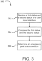
- a method 390 of controlling an emergency park brake system includes receiving a first status and a second status of a user input interface at step 392.
- An emergency park brake controller will receive the first status of the user input interface from a first displacement sensor and the emergency park brake controller will also receive the second status of the user input interface from a second displacement sensor.
- the method 390 further includes comparing the first status and the second status at step 394. In various embodiments, comparing the first status of the user input interface with the second status of the user input interface yields comparison data.
- the method 390 further includes determining an emergency park brake condition at step 396. Determining the emergency park brake condition (step 396) is performed by the emergency park brake controller 220 and is based on the comparison data.
- determining the emergency park brake condition at step 396 includes determining whether the comparison data comprises a threshold difference between the first status of the user input interface and the second status of the user input interface.
- the method may also include an additional step of determining, by the emergency park brake controller and based on the emergency park brake condition (e.g., the "first" emergency park brake condition), a second emergency park brake condition.
- the second park brake condition is performed in response to determining the first emergency park condition, according to various embodiments. For example, in various embodiments, determining the second emergency park brake condition is performed in response to the first emergency park brake condition indicating an operative condition.
- any reference to attached, fixed, connected, coupled or the like may include permanent (e.g., integral), removable, temporary, partial, full, and/or any other possible attachment option.
- permanent e.g., integral
- removable temporary, partial, full
- any other possible attachment option e.g., permanent, temporary, partial, full, and/or any other possible attachment option.
- Different cross-hatching is used throughout the figures to denote different parts but not necessarily to denote the same or different materials.
- any of the method or process descriptions may be executed in any order and are not necessarily limited to the order presented.
- any reference to singular includes plural embodiments, and any reference to more than one component or step may include a singular embodiment or step.
- Elements and steps in the figures are illustrated for simplicity and clarity and have not necessarily been rendered according to any particular sequence. For example, steps that may be performed concurrently or in different order are illustrated in the figures to help to improve understanding of embodiments of the present disclosure.
- Any reference to attached, fixed, connected or the like may include permanent, removable, temporary, partial, full and/or any other possible attachment option. Additionally, any reference to without contact (or similar phrases) may also include reduced contact or minimal contact. Surface shading lines may be used throughout the figures to denote different parts or areas but not necessarily to denote the same or different materials. In some cases, reference coordinates may be specific to each figure.
- references to “one embodiment”, “an embodiment”, “various embodiments”, etc. indicate that the embodiment described may include a particular feature, structure, or characteristic, but every embodiment may not necessarily include the particular feature, structure, or characteristic. Moreover, such phrases are not necessarily referring to the same embodiment. After reading the description, it will be apparent to one skilled in the relevant art(s) how to implement the disclosure in alternative embodiments.
Landscapes
- Engineering & Computer Science (AREA)
- Mechanical Engineering (AREA)
- Transportation (AREA)
- Aviation & Aerospace Engineering (AREA)
- Valves And Accessory Devices For Braking Systems (AREA)
- Regulating Braking Force (AREA)
Claims (12)
- Notfeststellbremssystem (200) eines Luftfahrzeugs (10), wobei das Notfeststellbremssystem umfasst:eine Benutzereingabeschnittstelle (205), die zum Empfangen einer Aktivierungseingabe von einem Benutzer konfiguriert ist, wobei die Aktivierungseingabe eine Verschiebung der Benutzereingabeschnittstelle umfasst;einen ersten Verschiebungssensor (210), der mit der Benutzereingabeschnittstelle gekoppelt ist, wobei der erste Verschiebungssensor dazu konfiguriert ist, die Verschiebung der Benutzereingabeschnittstelle zu erkennen und einen ersten Status (214) der Benutzereingabeschnittstelle zu erzeugen;einen zweiten Verschiebungssensor (212), der mit der Benutzereingabeschnittstelle gekoppelt ist, wobei der zweite Verschiebungssensor dazu konfiguriert ist, die Verschiebung der Benutzereingabeschnittstelle zu erkennen und einen zweiten Status (216) der Benutzereingabeschnittstelle zu erzeugen;eine Notfeststellbremssteuerung (220), die einen Prozessor aufweist und zum Durchführen von Vorgängen konfiguriert ist, die umfassen:Empfangen des ersten Status der Benutzereingabeschnittstelle und des zweiten Status der Benutzereingabeschnittstelle durch den Prozessor;Vergleichen des ersten Status der Benutzereingabeschnittstelle durch den Prozessor mit dem zweiten Status der Benutzereingabeschnittstelle, um Vergleichsdaten zu liefern; undBestimmen eines Notfeststellbremszustands durch den Prozessor und basierend auf den Vergleichsdaten, wobei das Bestimmen des Notfeststellbremszustands das Bestimmen umfasst, ob die Vergleichsdaten eine Schwellenwertdifferenz zwischen dem ersten Status der Benutzereingabeschnittstelle und dem zweiten Status der Benutzereingabeschnittstelle umfassen;Senden eines Bremsbefehls durch den Prozessor an eine Bremsbaugruppe als Reaktion auf das Bestimmen, dass die Vergleichsdaten geringer als die Schwellenwertdifferenz sind und somit der Notfeststellbremszustand einen Betriebszustand anzeigt; undSenden eines Bremsbefehls durch den Prozessor an die Bremsbaugruppe als Reaktion auf das Bestimmen, dass die Vergleichsdaten größer als die Schwellenwertdifferenz sind und somit der Notfeststellbremszustand einen Fehlerzustand anzeigt.
- Notfeststellbremssystem nach Anspruch 1, wobei als Reaktion darauf, dass der Notfeststellbremszustand den Fehlerzustand anzeigt, die Vorgänge das Anzeigen eines Indikators des Fehlerzustands auf einer Anzeigevorrichtung umfassen.
- Notfeststellbremssystem nach einem der vorhergehenden Ansprüche, wobei die Schwellenwertdifferenz etwa 5 % beträgt oder wobei die Schwellenwertdifferenz etwa 3 % beträgt.
- Notfeststellbremssystem nach einem der vorhergehenden Ansprüche, wobei der Notfeststellbremszustand ein erster Notfeststellbremszustand ist, wobei die Vorgänge ferner das Bestimmen eines zweiten Notfeststellbremszustands durch den Prozessor und basierend auf dem ersten Status der Benutzereingabeschnittstelle und dem zweiten Status der Benutzereingabeschnittstelle umfassen.
- Notfeststellbremssystem nach Anspruch 4, wobei das Bestimmen des zweiten Notfeststellbremszustands auf dem ersten Notfeststellbremszustand basiert und wobei das Bestimmen des zweiten Notfeststellbremszustands als Reaktion darauf durchgeführt wird, dass der erste Notfeststellbremszustands einen Betriebszustand anzeigt.
- Notfeststellbremssystem nach Anspruch 4, wobei das Bestimmen des zweiten Notfeststellbremszustands das Vergleichen der Verschiebung der Benutzereingabeschnittstelle, die durch den ersten Status der Benutzereingabeschnittstelle und den zweiten Status der Benutzereingabeschnittstelle angezeigt wird, mit einer Schwellenwertverschiebung umfasst.
- Notfeststellbremssystem nach Anspruch 6, wobei die Vorgänge ferner das Bestimmen umfassen, ob die Verschiebung der Benutzereingabeschnittstelle größer als die Schwellenwertverschiebung ist.
- Notfeststellbremssystem nach Anspruch 7, wobei der zweite Notfeststellbremszustand als Reaktion darauf, dass die Verschiebung der Benutzereingabeschnittstelle geringer als die Schwellenwertverschiebung ist, eine Nullanforderung anzeigt oder wobei der zweite Notfeststellbremszustand als Reaktion darauf, dass die Verschiebung der Benutzereingabeschnittstelle größer als die Schwellenwertverschiebung ist, eine Bremsanforderung anzeigt.
- Notfeststellbremssystem nach Anspruch 7 oder 8, wobei die Schwellenwertverschiebung etwa 15 % bis etwa 20 % von einer Nullposition der Benutzereingabeschnittstelle bis zu einer maximalen Verschiebungsposition beträgt.
- Notfeststellbremssystem nach einem der vorhergehenden Ansprüche,
wobei die Notfeststellbremssteuerung (220) ferner einen Prozessor und einen greifbaren, nichtflüchtigen Speicher umfasst, der zum Kommunizieren mit dem Prozessor konfiguriert ist, wobei der greifbare, nichtflüchtige Speicher darauf gespeicherte Anweisungen aufweist, die als Reaktion auf die Ausführung durch den Prozessor das Notfeststellbremssystem zum Durchführen von Vorgängen veranlassen, die umfassen:Empfangen des ersten Status der Benutzereingabeschnittstelle und des zweiten Status der Benutzereingabeschnittstelle durch den Prozessor;Vergleichen des ersten Status der Benutzereingabeschnittstelle durch den Prozessor mit dem zweiten Status der Benutzereingabeschnittstelle, um die Vergleichsdaten zu liefern;Bestimmen eines ersten Notfeststellbremszustands durch den Prozessor basierend darauf, ob die Vergleichsdaten eine Schwellenwertdifferenz zwischen dem ersten Status der Benutzereingabeschnittstelle und dem zweiten Status der Benutzereingabeschnittstelle ergeben; undBestimmen eines zweiten Notfeststellbremszustands durch den Prozessor und basierend auf dem ersten Notfeststellbremszustand. - Verfahren zur Steuerung eines Notfeststellbremssystems (200) eines Luftfahrzeugs (10), wobei das Verfahren umfasst:Empfangen eines ersten Status (214) einer Benutzereingabeschnittstelle (205) von einem ersten Verschiebungssensor (210) und eines zweiten Status (216) der Benutzereingabeschnittstelle von einem zweiten Verschiebungssensor (212) durch eine Notfeststellbremssteuerung (220) ;Vergleichen des ersten Status der Benutzereingabeschnittstelle durch die Notfeststellbremssteuerung mit dem zweiten Status der Benutzereingabeschnittstelle, um Vergleichsdaten zu liefern; undBestimmen eines Notfeststellbremszustands durch die Notfeststellbremssteuerung und basierend auf den Vergleichsdaten, wobei das Bestimmen des Notfeststellbremszustands das Bestimmen umfasst, ob die Vergleichsdaten eine Schwellenwertdifferenz zwischen dem ersten Status der Benutzereingabeschnittstelle und dem zweiten Status der Benutzereingabeschnittstelle umfassen;Senden eines Bremsbefehls durch die Notfeststellbremssteuerung an eine Bremsbaugruppe als Reaktion auf das Bestimmen, dass die Vergleichsdaten kleiner als die Schwellenwertdifferenz sind und somit der Notfeststellbremszustand einen Betriebszustand anzeigt; undSenden eines Bremsbefehls durch die Notfeststellbremssteuerung an die Bremsbaugruppe als Reaktion auf das Bestimmen, dass die Vergleichsdaten größer als die Schwellenwertdifferenz sind und somit der Notfeststellbremszustand einen Fehlerzustand anzeigt.
- Verfahren nach Anspruch 11, wobei der Notfeststellbremszustand ein erster Notfeststellbremszustand ist, wobei das Verfahren ferner das Bestimmen eines zweiten Notfeststellbremszustands durch die Notfeststellbremssteuerung und basierend auf dem ersten Notfeststellbremszustand umfasst; und wobei vorzugsweise das Bestimmen des zweiten Notfeststellbremszustands als Reaktion darauf durchgeführt wird, dass der erste Notfeststellbremszustand einen Betriebszustand anzeigt.
Applications Claiming Priority (1)
| Application Number | Priority Date | Filing Date | Title |
|---|---|---|---|
| US15/490,563 US10518758B2 (en) | 2017-04-18 | 2017-04-18 | Emergency park brake system |
Publications (2)
| Publication Number | Publication Date |
|---|---|
| EP3392140A1 EP3392140A1 (de) | 2018-10-24 |
| EP3392140B1 true EP3392140B1 (de) | 2023-11-01 |
Family
ID=62025735
Family Applications (1)
| Application Number | Title | Priority Date | Filing Date |
|---|---|---|---|
| EP18168036.4A Active EP3392140B1 (de) | 2017-04-18 | 2018-04-18 | Notfeststellbremssystem |
Country Status (2)
| Country | Link |
|---|---|
| US (1) | US10518758B2 (de) |
| EP (1) | EP3392140B1 (de) |
Families Citing this family (3)
| Publication number | Priority date | Publication date | Assignee | Title |
|---|---|---|---|---|
| CN109606344B (zh) * | 2018-11-27 | 2021-01-15 | 江苏大学 | 一种拖挂式房车电磁制动器制动故障检测警报与处理系统及其控制方法 |
| FR3094695B1 (fr) * | 2019-04-05 | 2021-08-13 | Safran Landing Systems | Procédé de pilotage d’un dispositif de freinage |
| US12269450B2 (en) * | 2023-08-30 | 2025-04-08 | Bendix Commercial Vehicle Systems Llc | Park brake controller with multiple communication channels and failsafe methods for use therewith |
Family Cites Families (11)
| Publication number | Priority date | Publication date | Assignee | Title |
|---|---|---|---|---|
| DE19510525A1 (de) | 1995-03-23 | 1996-09-26 | Bosch Gmbh Robert | Verfahren und Vorrichtung zur Steuerung bzw. Regelung der Bremsanlage eines Fahrzeugs |
| US7781673B2 (en) * | 2005-07-14 | 2010-08-24 | Konarka Technologies, Inc. | Polymers with low band gaps and high charge mobility |
| US9085285B2 (en) * | 2006-01-19 | 2015-07-21 | Hydro-Aire, Inc. | System and method for aircraft brake metering to alleviate structural loading |
| WO2009089551A2 (en) | 2008-01-11 | 2009-07-16 | General Atomics | Braking system with linear actuator |
| US8280603B2 (en) * | 2009-03-09 | 2012-10-02 | Goodrich Corporation | System and method to determine brake pedal sensor failure |
| US8112213B2 (en) | 2009-04-24 | 2012-02-07 | Goodrich Corporation | Electric brake architecture with dissimilar emergency braking path |
| US9216720B2 (en) | 2009-04-30 | 2015-12-22 | Goodrich Corporation | Differential emergency/park electric brake system |
| US9227608B2 (en) | 2009-08-12 | 2016-01-05 | Meggitt Aircraft Braking Systems | Decentralized electric brake system |
| US20110226569A1 (en) | 2010-03-19 | 2011-09-22 | Hydro-Aire, Inc. | Electronic motor actuators brake inhibit for aircraft braking system |
| US9669810B2 (en) | 2012-01-10 | 2017-06-06 | Honeywell International Inc. | Brake assembly including independently activatable brake actuators |
| US9205918B2 (en) * | 2013-11-08 | 2015-12-08 | Goodrich Corporation | System and method for maximum braking |
-
2017
- 2017-04-18 US US15/490,563 patent/US10518758B2/en active Active
-
2018
- 2018-04-18 EP EP18168036.4A patent/EP3392140B1/de active Active
Also Published As
| Publication number | Publication date |
|---|---|
| US10518758B2 (en) | 2019-12-31 |
| EP3392140A1 (de) | 2018-10-24 |
| US20180297563A1 (en) | 2018-10-18 |
Similar Documents
| Publication | Publication Date | Title |
|---|---|---|
| US11639160B2 (en) | Electrical power connection in an emergency park brake system | |
| EP3659877B1 (de) | System und verfahren zur detektierung eines bremsversagen durch die bremsung während des einfahrens des fahrwerks | |
| EP3564083B1 (de) | Prognosen für drucksensoren von hydraulischen bremssystemen | |
| EP3748189A1 (de) | Einziehbarer elektronischer verschleissstift | |
| EP3333069B1 (de) | Systeme und verfahren für flugzeugnotfall- und feststellbremsen | |
| EP2565093B1 (de) | Systeme und Verfahren zum Testen eines Bremssystems | |
| EP3357772B1 (de) | Hydraulische parkbremsanlage und verfahren | |
| EP2876011B1 (de) | System und Verfahren für Vollbremsung | |
| EP3348474B1 (de) | System und verfahren zum automatischen bremsen mit kursverlaufsanpassung | |
| EP3279045B1 (de) | Systeme und verfahren zur bremsensteuerung | |
| EP3392140A1 (de) | Notfeststellbremssystem | |
| EP3358578B1 (de) | Verschiebungssensor | |
| EP3909818B1 (de) | Erkennung von bremsversagen unter verwendung der radgeschwindigkeit beim einfahren des fahrwerks | |
| US10710561B2 (en) | Deceleration pedal control for braking systems | |
| US10647306B2 (en) | Measurement of contact maintaining control valve current for a hydraulic actuator | |
| EP4183680B1 (de) | Bremssysteme und -verfahren mit haptikeinstellung | |
| US20190016326A1 (en) | Brake handle for emergency electric braking |
Legal Events
| Date | Code | Title | Description |
|---|---|---|---|
| PUAI | Public reference made under article 153(3) epc to a published international application that has entered the european phase |
Free format text: ORIGINAL CODE: 0009012 |
|
| STAA | Information on the status of an ep patent application or granted ep patent |
Free format text: STATUS: THE APPLICATION HAS BEEN PUBLISHED |
|
| AK | Designated contracting states |
Kind code of ref document: A1 Designated state(s): AL AT BE BG CH CY CZ DE DK EE ES FI FR GB GR HR HU IE IS IT LI LT LU LV MC MK MT NL NO PL PT RO RS SE SI SK SM TR |
|
| AX | Request for extension of the european patent |
Extension state: BA ME |
|
| STAA | Information on the status of an ep patent application or granted ep patent |
Free format text: STATUS: REQUEST FOR EXAMINATION WAS MADE |
|
| 17P | Request for examination filed |
Effective date: 20190424 |
|
| RBV | Designated contracting states (corrected) |
Designated state(s): AL AT BE BG CH CY CZ DE DK EE ES FI FR GB GR HR HU IE IS IT LI LT LU LV MC MK MT NL NO PL PT RO RS SE SI SK SM TR |
|
| STAA | Information on the status of an ep patent application or granted ep patent |
Free format text: STATUS: EXAMINATION IS IN PROGRESS |
|
| 17Q | First examination report despatched |
Effective date: 20200921 |
|
| GRAP | Despatch of communication of intention to grant a patent |
Free format text: ORIGINAL CODE: EPIDOSNIGR1 |
|
| STAA | Information on the status of an ep patent application or granted ep patent |
Free format text: STATUS: GRANT OF PATENT IS INTENDED |
|
| RIC1 | Information provided on ipc code assigned before grant |
Ipc: B60T 8/17 20060101ALN20230425BHEP Ipc: B64C 25/44 20060101AFI20230425BHEP |
|
| INTG | Intention to grant announced |
Effective date: 20230531 |
|
| GRAS | Grant fee paid |
Free format text: ORIGINAL CODE: EPIDOSNIGR3 |
|
| GRAA | (expected) grant |
Free format text: ORIGINAL CODE: 0009210 |
|
| STAA | Information on the status of an ep patent application or granted ep patent |
Free format text: STATUS: THE PATENT HAS BEEN GRANTED |
|
| AK | Designated contracting states |
Kind code of ref document: B1 Designated state(s): AL AT BE BG CH CY CZ DE DK EE ES FI FR GB GR HR HU IE IS IT LI LT LU LV MC MK MT NL NO PL PT RO RS SE SI SK SM TR |
|
| P01 | Opt-out of the competence of the unified patent court (upc) registered |
Effective date: 20230922 |
|
| REG | Reference to a national code |
Ref country code: GB Ref legal event code: FG4D |
|
| REG | Reference to a national code |
Ref country code: CH Ref legal event code: EP |
|
| REG | Reference to a national code |
Ref country code: IE Ref legal event code: FG4D |
|
| REG | Reference to a national code |
Ref country code: DE Ref legal event code: R096 Ref document number: 602018060260 Country of ref document: DE |
|
| REG | Reference to a national code |
Ref country code: LT Ref legal event code: MG9D |
|
| REG | Reference to a national code |
Ref country code: NL Ref legal event code: MP Effective date: 20231101 |
|
| PG25 | Lapsed in a contracting state [announced via postgrant information from national office to epo] |
Ref country code: GR Free format text: LAPSE BECAUSE OF FAILURE TO SUBMIT A TRANSLATION OF THE DESCRIPTION OR TO PAY THE FEE WITHIN THE PRESCRIBED TIME-LIMIT Effective date: 20240202 |
|
| PG25 | Lapsed in a contracting state [announced via postgrant information from national office to epo] |
Ref country code: IS Free format text: LAPSE BECAUSE OF FAILURE TO SUBMIT A TRANSLATION OF THE DESCRIPTION OR TO PAY THE FEE WITHIN THE PRESCRIBED TIME-LIMIT Effective date: 20240301 |
|
| PG25 | Lapsed in a contracting state [announced via postgrant information from national office to epo] |
Ref country code: LT Free format text: LAPSE BECAUSE OF FAILURE TO SUBMIT A TRANSLATION OF THE DESCRIPTION OR TO PAY THE FEE WITHIN THE PRESCRIBED TIME-LIMIT Effective date: 20231101 |
|
| REG | Reference to a national code |
Ref country code: AT Ref legal event code: MK05 Ref document number: 1626950 Country of ref document: AT Kind code of ref document: T Effective date: 20231101 |
|
| PG25 | Lapsed in a contracting state [announced via postgrant information from national office to epo] |
Ref country code: NL Free format text: LAPSE BECAUSE OF FAILURE TO SUBMIT A TRANSLATION OF THE DESCRIPTION OR TO PAY THE FEE WITHIN THE PRESCRIBED TIME-LIMIT Effective date: 20231101 |
|
| PG25 | Lapsed in a contracting state [announced via postgrant information from national office to epo] |
Ref country code: AT Free format text: LAPSE BECAUSE OF FAILURE TO SUBMIT A TRANSLATION OF THE DESCRIPTION OR TO PAY THE FEE WITHIN THE PRESCRIBED TIME-LIMIT Effective date: 20231101 |
|
| PG25 | Lapsed in a contracting state [announced via postgrant information from national office to epo] |
Ref country code: ES Free format text: LAPSE BECAUSE OF FAILURE TO SUBMIT A TRANSLATION OF THE DESCRIPTION OR TO PAY THE FEE WITHIN THE PRESCRIBED TIME-LIMIT Effective date: 20231101 |
|
| PG25 | Lapsed in a contracting state [announced via postgrant information from national office to epo] |
Ref country code: NL Free format text: LAPSE BECAUSE OF FAILURE TO SUBMIT A TRANSLATION OF THE DESCRIPTION OR TO PAY THE FEE WITHIN THE PRESCRIBED TIME-LIMIT Effective date: 20231101 Ref country code: LT Free format text: LAPSE BECAUSE OF FAILURE TO SUBMIT A TRANSLATION OF THE DESCRIPTION OR TO PAY THE FEE WITHIN THE PRESCRIBED TIME-LIMIT Effective date: 20231101 Ref country code: IS Free format text: LAPSE BECAUSE OF FAILURE TO SUBMIT A TRANSLATION OF THE DESCRIPTION OR TO PAY THE FEE WITHIN THE PRESCRIBED TIME-LIMIT Effective date: 20240301 Ref country code: GR Free format text: LAPSE BECAUSE OF FAILURE TO SUBMIT A TRANSLATION OF THE DESCRIPTION OR TO PAY THE FEE WITHIN THE PRESCRIBED TIME-LIMIT Effective date: 20240202 Ref country code: ES Free format text: LAPSE BECAUSE OF FAILURE TO SUBMIT A TRANSLATION OF THE DESCRIPTION OR TO PAY THE FEE WITHIN THE PRESCRIBED TIME-LIMIT Effective date: 20231101 Ref country code: BG Free format text: LAPSE BECAUSE OF FAILURE TO SUBMIT A TRANSLATION OF THE DESCRIPTION OR TO PAY THE FEE WITHIN THE PRESCRIBED TIME-LIMIT Effective date: 20240201 Ref country code: AT Free format text: LAPSE BECAUSE OF FAILURE TO SUBMIT A TRANSLATION OF THE DESCRIPTION OR TO PAY THE FEE WITHIN THE PRESCRIBED TIME-LIMIT Effective date: 20231101 Ref country code: PT Free format text: LAPSE BECAUSE OF FAILURE TO SUBMIT A TRANSLATION OF THE DESCRIPTION OR TO PAY THE FEE WITHIN THE PRESCRIBED TIME-LIMIT Effective date: 20240301 |
|
| PG25 | Lapsed in a contracting state [announced via postgrant information from national office to epo] |
Ref country code: SE Free format text: LAPSE BECAUSE OF FAILURE TO SUBMIT A TRANSLATION OF THE DESCRIPTION OR TO PAY THE FEE WITHIN THE PRESCRIBED TIME-LIMIT Effective date: 20231101 Ref country code: RS Free format text: LAPSE BECAUSE OF FAILURE TO SUBMIT A TRANSLATION OF THE DESCRIPTION OR TO PAY THE FEE WITHIN THE PRESCRIBED TIME-LIMIT Effective date: 20231101 Ref country code: PL Free format text: LAPSE BECAUSE OF FAILURE TO SUBMIT A TRANSLATION OF THE DESCRIPTION OR TO PAY THE FEE WITHIN THE PRESCRIBED TIME-LIMIT Effective date: 20231101 Ref country code: NO Free format text: LAPSE BECAUSE OF FAILURE TO SUBMIT A TRANSLATION OF THE DESCRIPTION OR TO PAY THE FEE WITHIN THE PRESCRIBED TIME-LIMIT Effective date: 20240201 Ref country code: LV Free format text: LAPSE BECAUSE OF FAILURE TO SUBMIT A TRANSLATION OF THE DESCRIPTION OR TO PAY THE FEE WITHIN THE PRESCRIBED TIME-LIMIT Effective date: 20231101 Ref country code: HR Free format text: LAPSE BECAUSE OF FAILURE TO SUBMIT A TRANSLATION OF THE DESCRIPTION OR TO PAY THE FEE WITHIN THE PRESCRIBED TIME-LIMIT Effective date: 20231101 |
|
| PG25 | Lapsed in a contracting state [announced via postgrant information from national office to epo] |
Ref country code: DK Free format text: LAPSE BECAUSE OF FAILURE TO SUBMIT A TRANSLATION OF THE DESCRIPTION OR TO PAY THE FEE WITHIN THE PRESCRIBED TIME-LIMIT Effective date: 20231101 |
|
| PG25 | Lapsed in a contracting state [announced via postgrant information from national office to epo] |
Ref country code: CZ Free format text: LAPSE BECAUSE OF FAILURE TO SUBMIT A TRANSLATION OF THE DESCRIPTION OR TO PAY THE FEE WITHIN THE PRESCRIBED TIME-LIMIT Effective date: 20231101 |
|
| PG25 | Lapsed in a contracting state [announced via postgrant information from national office to epo] |
Ref country code: SK Free format text: LAPSE BECAUSE OF FAILURE TO SUBMIT A TRANSLATION OF THE DESCRIPTION OR TO PAY THE FEE WITHIN THE PRESCRIBED TIME-LIMIT Effective date: 20231101 |
|
| PG25 | Lapsed in a contracting state [announced via postgrant information from national office to epo] |
Ref country code: SM Free format text: LAPSE BECAUSE OF FAILURE TO SUBMIT A TRANSLATION OF THE DESCRIPTION OR TO PAY THE FEE WITHIN THE PRESCRIBED TIME-LIMIT Effective date: 20231101 Ref country code: SK Free format text: LAPSE BECAUSE OF FAILURE TO SUBMIT A TRANSLATION OF THE DESCRIPTION OR TO PAY THE FEE WITHIN THE PRESCRIBED TIME-LIMIT Effective date: 20231101 Ref country code: IT Free format text: LAPSE BECAUSE OF FAILURE TO SUBMIT A TRANSLATION OF THE DESCRIPTION OR TO PAY THE FEE WITHIN THE PRESCRIBED TIME-LIMIT Effective date: 20231101 Ref country code: EE Free format text: LAPSE BECAUSE OF FAILURE TO SUBMIT A TRANSLATION OF THE DESCRIPTION OR TO PAY THE FEE WITHIN THE PRESCRIBED TIME-LIMIT Effective date: 20231101 Ref country code: DK Free format text: LAPSE BECAUSE OF FAILURE TO SUBMIT A TRANSLATION OF THE DESCRIPTION OR TO PAY THE FEE WITHIN THE PRESCRIBED TIME-LIMIT Effective date: 20231101 Ref country code: CZ Free format text: LAPSE BECAUSE OF FAILURE TO SUBMIT A TRANSLATION OF THE DESCRIPTION OR TO PAY THE FEE WITHIN THE PRESCRIBED TIME-LIMIT Effective date: 20231101 |
|
| REG | Reference to a national code |
Ref country code: DE Ref legal event code: R097 Ref document number: 602018060260 Country of ref document: DE |
|
| PLBE | No opposition filed within time limit |
Free format text: ORIGINAL CODE: 0009261 |
|
| STAA | Information on the status of an ep patent application or granted ep patent |
Free format text: STATUS: NO OPPOSITION FILED WITHIN TIME LIMIT |
|
| 26N | No opposition filed |
Effective date: 20240802 |
|
| PG25 | Lapsed in a contracting state [announced via postgrant information from national office to epo] |
Ref country code: SI Free format text: LAPSE BECAUSE OF FAILURE TO SUBMIT A TRANSLATION OF THE DESCRIPTION OR TO PAY THE FEE WITHIN THE PRESCRIBED TIME-LIMIT Effective date: 20231101 |
|
| PG25 | Lapsed in a contracting state [announced via postgrant information from national office to epo] |
Ref country code: SI Free format text: LAPSE BECAUSE OF FAILURE TO SUBMIT A TRANSLATION OF THE DESCRIPTION OR TO PAY THE FEE WITHIN THE PRESCRIBED TIME-LIMIT Effective date: 20231101 |
|
| REG | Reference to a national code |
Ref country code: DE Ref legal event code: R119 Ref document number: 602018060260 Country of ref document: DE |
|
| PG25 | Lapsed in a contracting state [announced via postgrant information from national office to epo] |
Ref country code: MC Free format text: LAPSE BECAUSE OF FAILURE TO SUBMIT A TRANSLATION OF THE DESCRIPTION OR TO PAY THE FEE WITHIN THE PRESCRIBED TIME-LIMIT Effective date: 20231101 |
|
| PG25 | Lapsed in a contracting state [announced via postgrant information from national office to epo] |
Ref country code: MC Free format text: LAPSE BECAUSE OF FAILURE TO SUBMIT A TRANSLATION OF THE DESCRIPTION OR TO PAY THE FEE WITHIN THE PRESCRIBED TIME-LIMIT Effective date: 20231101 |
|
| REG | Reference to a national code |
Ref country code: CH Ref legal event code: PL |
|
| PG25 | Lapsed in a contracting state [announced via postgrant information from national office to epo] |
Ref country code: LU Free format text: LAPSE BECAUSE OF NON-PAYMENT OF DUE FEES Effective date: 20240418 |
|
| REG | Reference to a national code |
Ref country code: BE Ref legal event code: MM Effective date: 20240430 |
|
| PG25 | Lapsed in a contracting state [announced via postgrant information from national office to epo] |
Ref country code: LU Free format text: LAPSE BECAUSE OF NON-PAYMENT OF DUE FEES Effective date: 20240418 |
|
| PG25 | Lapsed in a contracting state [announced via postgrant information from national office to epo] |
Ref country code: DE Free format text: LAPSE BECAUSE OF NON-PAYMENT OF DUE FEES Effective date: 20241105 |
|
| PG25 | Lapsed in a contracting state [announced via postgrant information from national office to epo] |
Ref country code: BE Free format text: LAPSE BECAUSE OF NON-PAYMENT OF DUE FEES Effective date: 20240430 |
|
| PG25 | Lapsed in a contracting state [announced via postgrant information from national office to epo] |
Ref country code: DE Free format text: LAPSE BECAUSE OF NON-PAYMENT OF DUE FEES Effective date: 20241105 Ref country code: BE Free format text: LAPSE BECAUSE OF NON-PAYMENT OF DUE FEES Effective date: 20240430 Ref country code: CH Free format text: LAPSE BECAUSE OF NON-PAYMENT OF DUE FEES Effective date: 20240430 |
|
| PG25 | Lapsed in a contracting state [announced via postgrant information from national office to epo] |
Ref country code: IE Free format text: LAPSE BECAUSE OF NON-PAYMENT OF DUE FEES Effective date: 20240418 |
|
| PG25 | Lapsed in a contracting state [announced via postgrant information from national office to epo] |
Ref country code: CY Free format text: LAPSE BECAUSE OF FAILURE TO SUBMIT A TRANSLATION OF THE DESCRIPTION OR TO PAY THE FEE WITHIN THE PRESCRIBED TIME-LIMIT; INVALID AB INITIO Effective date: 20180418 |
|
| PG25 | Lapsed in a contracting state [announced via postgrant information from national office to epo] |
Ref country code: RO Free format text: LAPSE BECAUSE OF FAILURE TO SUBMIT A TRANSLATION OF THE DESCRIPTION OR TO PAY THE FEE WITHIN THE PRESCRIBED TIME-LIMIT Effective date: 20231101 |
|
| PG25 | Lapsed in a contracting state [announced via postgrant information from national office to epo] |
Ref country code: HU Free format text: LAPSE BECAUSE OF FAILURE TO SUBMIT A TRANSLATION OF THE DESCRIPTION OR TO PAY THE FEE WITHIN THE PRESCRIBED TIME-LIMIT; INVALID AB INITIO Effective date: 20180418 |
|
| PG25 | Lapsed in a contracting state [announced via postgrant information from national office to epo] |
Ref country code: FI Free format text: LAPSE BECAUSE OF FAILURE TO SUBMIT A TRANSLATION OF THE DESCRIPTION OR TO PAY THE FEE WITHIN THE PRESCRIBED TIME-LIMIT Effective date: 20231101 |
|
| PGFP | Annual fee paid to national office [announced via postgrant information from national office to epo] |
Ref country code: GB Payment date: 20260319 Year of fee payment: 9 |
|
| PGFP | Annual fee paid to national office [announced via postgrant information from national office to epo] |
Ref country code: FR Payment date: 20260319 Year of fee payment: 9 |