EP3392143B1 - Verbesserte daten transfer system eines hubschraubers - Google Patents
Verbesserte daten transfer system eines hubschraubers Download PDFInfo
- Publication number
- EP3392143B1 EP3392143B1 EP18167659.4A EP18167659A EP3392143B1 EP 3392143 B1 EP3392143 B1 EP 3392143B1 EP 18167659 A EP18167659 A EP 18167659A EP 3392143 B1 EP3392143 B1 EP 3392143B1
- Authority
- EP
- European Patent Office
- Prior art keywords
- power
- aircraft
- data
- bus
- line communication
- Prior art date
- Legal status (The legal status is an assumption and is not a legal conclusion. Google has not performed a legal analysis and makes no representation as to the accuracy of the status listed.)
- Active
Links
Images


Classifications
-
- H—ELECTRICITY
- H04—ELECTRIC COMMUNICATION TECHNIQUE
- H04B—TRANSMISSION
- H04B3/00—Line transmission systems
- H04B3/54—Systems for transmission via power distribution lines
-
- B—PERFORMING OPERATIONS; TRANSPORTING
- B64—AIRCRAFT; AVIATION; COSMONAUTICS
- B64C—AEROPLANES; HELICOPTERS
- B64C27/00—Rotorcraft; Rotors peculiar thereto
- B64C27/04—Helicopters
-
- B—PERFORMING OPERATIONS; TRANSPORTING
- B64—AIRCRAFT; AVIATION; COSMONAUTICS
- B64D—EQUIPMENT FOR FITTING IN OR TO AIRCRAFT; FLIGHT SUITS; PARACHUTES; ARRANGEMENT OR MOUNTING OF POWER PLANTS OR PROPULSION TRANSMISSIONS IN AIRCRAFT
- B64D41/00—Power installations for auxiliary purposes
-
- G—PHYSICS
- G07—CHECKING-DEVICES
- G07C—TIME OR ATTENDANCE REGISTERS; REGISTERING OR INDICATING THE WORKING OF MACHINES; GENERATING RANDOM NUMBERS; VOTING OR LOTTERY APPARATUS; ARRANGEMENTS, SYSTEMS OR APPARATUS FOR CHECKING NOT PROVIDED FOR ELSEWHERE
- G07C5/00—Registering or indicating the working of vehicles
- G07C5/08—Registering or indicating performance data other than driving, working, idle, or waiting time, with or without registering driving, working, idle or waiting time
- G07C5/0808—Diagnosing performance data
-
- B—PERFORMING OPERATIONS; TRANSPORTING
- B64—AIRCRAFT; AVIATION; COSMONAUTICS
- B64D—EQUIPMENT FOR FITTING IN OR TO AIRCRAFT; FLIGHT SUITS; PARACHUTES; ARRANGEMENT OR MOUNTING OF POWER PLANTS OR PROPULSION TRANSMISSIONS IN AIRCRAFT
- B64D2221/00—Electric power distribution systems onboard aircraft
-
- Y—GENERAL TAGGING OF NEW TECHNOLOGICAL DEVELOPMENTS; GENERAL TAGGING OF CROSS-SECTIONAL TECHNOLOGIES SPANNING OVER SEVERAL SECTIONS OF THE IPC; TECHNICAL SUBJECTS COVERED BY FORMER USPC CROSS-REFERENCE ART COLLECTIONS [XRACs] AND DIGESTS
- Y02—TECHNOLOGIES OR APPLICATIONS FOR MITIGATION OR ADAPTATION AGAINST CLIMATE CHANGE
- Y02T—CLIMATE CHANGE MITIGATION TECHNOLOGIES RELATED TO TRANSPORTATION
- Y02T50/00—Aeronautics or air transport
- Y02T50/40—Weight reduction
Definitions
- the present disclosure relates generally to data transfer systems, and in particular, to data transfer systems in aircraft.
- a health and usage management system (HUMS) in an aircraft uses a data transfer system to gather information about extremities of the aircraft, such as a tail boom section of a rotorcraft.
- the main HUMS is located in the main fuselage of the aircraft where the power source is also located.
- the HUMS data transfer system requires large amounts of wiring, wire hangers, and connectors to collect and send data from the extremity of the aircraft to the health and usage management system located in the main fuselage. A simpler and more efficient data transfer system is needed.
- WO2015/126686 discloses a fault monitoring system for an aircraft including a processor having a fault diagnosis algorithm.
- the present invention provides an aircraft including a system for data transfer as claimed in claim 1.
- the aircraft may be a rotorcraft, and the extremity may be a tail boom section of the rotorcraft.
- the present disclosure describes a data transfer system for a health and usage management system (HUMS) on a rotorcraft that uses power line communication nodes on existing power lines to bi-directionally and securely send data between the tail boom section and the main fuselage.
- HUMS health and usage management system
- the system reduces system weight, complexity, and installation effort by reducing the volume of wiring, wire hangers, and connectors, which also reduces manufacturing, operating, and maintenance costs. Without additional wires, the system can process larger volumes and different types of data, including data processing in the tail boom section itself, producing more efficient, functional, and advanced data transfer and analysis of the health status of the tail boom section. Further, power can be stored in the tail boom section when the power line is active so that health monitoring is possible when the aircraft is unpowered and inactive.
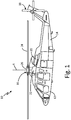
- FIG. 1 is a perspective view of rotorcraft 10.
- Rotorcraft 10 includes main fuselage 12, tail boom section 14, main rotor assembly 16, tail rotor system 18, engine 20, and main gearbox 22.
- Main rotor assembly 16 includes rotor blades 24 and rotor hub 26. Also shown in FIG. 1 is axis of rotation R.
- Rotorcraft 10 has main fuselage 12 with tail boom section 14 connected to and extending from main fuselage 12.
- Tail boom section 14 is an isolated extremity of main fuselage 12.
- Main rotor assembly 16 is mounted to a top of main fuselage 12 and tail rotor system 18 is mounted to tail boom section 14 near an aft end of tail boom section 14.
- Engine 20 (shown schematically) is disposed within main fuselage 12.
- Engine 20 is connected to main gearbox 22 (shown schematically).
- Main gearbox 22 is connected to main rotor assembly 16.
- Main rotor assembly 16 includes first ends of rotor blades 24 connected to rotor hub 26. Rotor blades 24 are connected around a circumference of rotor hub 26.
- Engine 20 and main gearbox 22 drive main rotor assembly 16 around an axis of rotation R.
- Power source 30 shown in FIGS. 2A and 2B
- Power is required in tail boom section 14 for motor actuation, lighting, heaters, anti-icing, and other components requiring power. Because tail boom section 14 is physically remote from main fuselage 12, power acquisition and sensors in tail boom section 14 require electrical connection to main fuselage 12 via wiring or other electrical connections.
- FIG. 2A is a block diagram of HUMS data transfer system 28 of rotorcraft 10.
- Rotorcraft 10 includes main fuselage 12, tail boom section 14, power source 30, power bus 32, and loads 33.
- HUMS data transfer system 28 includes: a first power line communication (PLC) node 34; digital sensor bus 36, which collects data 37 including accelerometer data 38, index sensor data 40, strain gauge monitoring data 42, current monitoring data 44, and structural health monitoring data 46; processor 48; energy storage module 50; second power line communication node 52; and HUMS 54.
- PLC power line communication
- Rotorcraft 10 has main fuselage 12 with tail boom section 14 connected to and extending from main fuselage 12.
- Tail boom section 14 is an isolated extremity of main fuselage 12.
- Power source 30 is located in main fuselage 12.
- Power bus 32 extends from power source 30 in main fuselage 12 to tail boom section 14.
- Power bus 32 extends to loads 33 in tail boom section 14. Loads 33 may include actuators, lights, heaters, anti-icing components, or other components requiring power.
- Power bus 32 includes wiring or power line structure used to provide power from main fuselage 12 to tail boom section 14.
- First power line communication node 34 is positioned on power bus 32 in tail boom section 14.
- First power line communication node 34 may be a plurality of power line communication nodes in tail boom section 14.
- Digital sensor bus 36 is connected to first power line communication node 34 in tail boom section 14.
- Digital sensor bus 36 includes a plurality of sensors that collect one or more of the following types of data 37: accelerometer data 38, index sensor data 40, strain gauge monitoring data 42, current monitoring data 44, and structural health monitoring data 46.
- Digital sensor bus 36 may be a smart sensing system.
- Digital sensor bus 36 can be a serial communications bus (e.g. RS485, RS482, or other serial communications bus), Ethernet, or any other suitable communications bus.
- Processor 48 is also connected to each of first power line communication node 34 and digital sensor bus 36.
- Processor 48 may process data 37 similarly to a HUMS.
- Energy storage module 50 is located in tail boom section 14. Energy storage module 50 is connected to power bus 32. In alternate embodiments, energy storage module 50 is connected to first power line communication node 34 (shown in FIG. 2B ).
- a second power line communication node 52 is positioned on power bus 32 in main fuselage 12. Second power line communication node 52 is connected to first power line communication node 34 through power bus 32. Second power line communication node 52 may be a plurality of power line communication nodes in main fuselage 12.
- HUMS 54 is connected to second power line communication node 52 through a digital interface.
- HUMS 54 is the main health and usage management system of rotorcraft 10.
- Power source 30 delivers electrical power to components of rotorcraft 10.
- Power bus 32 delivers power from power source 30 to tail boom section 14.
- Power bus 32 can carry AC power, DC power, or both AC power and DC power.
- Power delivered to tail boom section 14 can be used to power loads 33, such as actuators, lights, heaters, anti-icing components, and other components.
- Energy storage module 50 is connected to power bus 32 to store power from power bus 32 in tail boom section 14. Energy storage module 50 stores power whenever power is present on power bus 32.
- power bus 32 includes two or more individual power lines delivering power to tail boom section 14 for multiple power loads 33 (e.g. motor actuation, lighting, heaters, anti-icing, or other components requiring power)
- energy storage module 50 may store power from any power present.
- Energy storage module 50 supplies power to first power line communication node 34, digital sensor bus 36, and processor 48 when power is removed from power bus 32.
- Digital sensor bus 36 collects data 37, such as accelerometer data 38, index sensor data 40, strain gauge monitoring data 42, current monitoring data 44, and structural health monitoring data 46, and transmits data 37 to first power line communication node 34.
- Data 37 is used to monitor bearings, gear boxes, tail rotor system 18, and other components in tail boom section 14.
- digital sensor bus 36 transmits data 37 to processor 48 and processor 48 analyzes, compresses, and processes data 37 from digital sensor bus 36 before data 37 is transmitted to first power line communication node 34.
- Processor 48 can process data 37, such as structural health monitoring data 46, in tail boom section 14, such that data 37 is consolidated and analyzed in tail boom section 14 before it is forwarded to main fuselage 12 for further processing at HUMS 54.
- First power line communication node 34 modulates data 37 onto power bus 32 and transmits data 37 across power bus 32 to second power line communication node 52.
- Data 37 is transmitted using spread spectrum type transmission. As such, power and communications are combined on power bus 32.
- Data 37 may be transmitted across power bus 32 with or without power being present on power bus 32.
- Second power line communication node 52 transmits data 37 received from first power line communication node 34 to HUMS 54.
- Second power line communication node 52 can also modulate data 37 onto power bus 32 and transmit data 37 across power bus 32 to first power line communication node 34.
- communication between first power line communication node 34 and second power line communication node 52 is bi-directional.
- HUMS 54 further processes and analyzes data 37 to derive information about the health condition of rotorcraft 10.
- Energy storage module 50 stores power so that when power is removed from power loads 33 or the aircraft is inactive and unpowered the stored power can be used to supply power to first power line communication node 34, digital sensor bus 36, and processor 48.
- health monitoring is possible even when main fuselage 12 of rotorcraft 10 is not providing power.
- the ability to continue health monitoring when main fuselage 12 is not providing power is valuable.
- structural health monitoring for impact damage and strain and environmental sensing can be carried out on an unpowered rotorcraft 10.
- tail boom section 14 can recognize when rotorcraft 10 is operational by sensing that power is present.
- first power line communication node 34 Transmission of data 37 through first power line communication node 34, power bus 32, and second power line communication node 52 allows for data transfer from an isolated extremity of the rotorcraft, tail boom section 14, to main fuselage 12 using existing power bus 32. Because HUMS data transfer system 28 uses existing power bus 32 and monitoring of tail boom section 14 is largely isolated from the rest of condition monitoring, HUMS data transfer system 28 can be used in tail boom section 14 of rotorcraft 10 without having to upgrade any other systems on rotorcraft 10. Individual wire runs, including separate wire runs for each sensor collecting data 37, are not required to send data 37 from tail boom section 14 to main fuselage 12. As such, the volume of required wiring, wire hangers, and connectors is reduced, which reduces system weight, complexity, and installation effort.
- the reduction in wiring also reduces manufacturing, operating, and maintenance costs. Because the limitations of wire volume and weight are no longer present, a larger volume of data 37 can be collected and processed, and more types of data 37 can be collected and processed, adding capability and sophistication to tail boom section 14. More specifically, the reduction in weight resulting from the reduction in wiring may allow for the addition of sensors, including different types of sensors, which may not have been possible with the original weight budget. Further, processing some of data 37 in tail boom section 14 allows for reduced data transfer volume and more efficient transmission of data 37 to main fuselage 12 in addition to the opportunity to act on data 37 locally in tail boom section 14. More specifically, data fusion at processor 48 enables unnecessary or invalid raw data to be removed before data 37 is sent forward to main fuselage 12.
- Qualifying data 37 at processor 48 which includes making sure all of the necessary data sets are present before sending data forward to main fuselage 12, also makes data transfer more efficient.
- HUMS data transfer system 28 empowers HUMS 54 to collect more and different types of data, adding to the effectiveness and variety of data collection, fusion, processing, and feature extraction, resulting in more advanced and intelligent analysis of the health status of tail boom section 14 of rotorcraft 10. Further, more health monitoring features can be added over time without having to add additional wiring.
- data 37 is transmitted using spread spectrum type transmission, data 37 is transmitted at low signal energy, which makes data transmission hard to observe. More specifically, the transmission would look like noise routinely produced by power bus 32 and would therefore blend in with such noise. As a result, the transmission is secure. No electromagnetic signatures, which would otherwise be evident in a wireless transmission implementation, would emanate from rotorcraft 10.
- FIG. 2B is a block diagram of a second embodiment of HUMS data transfer system 28 of rotorcraft 10.
- energy storage module 50B is connected to first power line communication node 34 rather than directly to power bus 32.
- rotorcraft 10 includes main fuselage 12, tail boom section 14, power source 30, power bus 32, and loads 33.
- HUMS data transfer system 28 includes: a first power line communication node 34; digital sensor bus 36, which collects data 37 including accelerometer data 38, index sensor data 40, strain gauge monitoring data 42, current monitoring data 44, and structural health monitoring data 46; processor 48; energy storage module 50B; second power line communication node 52; and HUMS 54.
- Rotorcraft 10 has main fuselage 12 with tail boom section 14 connected to and extending from main fuselage 12.
- Tail boom section 14 is an isolated extremity of main fuselage 12.
- Power source 30 is located in main fuselage 12.
- Power bus 32 extends from power source 30 in main fuselage 12 to tail boom section 14.
- Power bus 32 extends to loads 33 in tail boom section 14. Loads 33 may include actuators, lights, heaters, anti-icing components, or other components requiring power.
- Power bus 32 includes wiring or power line structure used to provide power from main fuselage 12 to tail boom section 14.
- First power line communication node 34 is positioned on power bus 32 in tail boom section 14.
- First power line communication node 34 may be a plurality of power line communication nodes in tail boom section 14.
- Digital sensor bus 36 is connected to first power line communication node 34 in tail boom section 14.
- Digital sensor bus 36 includes a plurality of sensors that collect one or more of the following types of data 37: accelerometer data 38, index sensor data 40, strain gauge monitoring data 42, current monitoring data 44, and structural health monitoring data 46.
- Digital sensor bus 36 may be a smart sensing system.
- Digital sensor bus 36 can be a serial communications bus (e.g. RS485, RS482, or other serial communications bus), Ethernet, or any other suitable communications bus.
- Processor 48 is also connected to each of first power line communication node 34 and digital sensor bus 36.
- Processor 48 may process data 37 similarly to a HUMS.
- Energy storage module 50B is located in tail boom section 14. Energy storage module 50B is connected to first power line communication node 34. In alternate embodiments, energy storage module 50B is connected to power bus 32 (shown in FIG. 2A ).
- a second power line communication node 52 is positioned on power bus 32 in main fuselage 12. Second power line communication node 52 is connected to first power line communication node 34 through power bus 32. Second power line communication node 52 may be a plurality of power line communication nodes in main fuselage 12.
- HUMS 54 is connected to second power line communication node 52 through a digital interface.
- HUMS 54 is the main health and usage management system of rotorcraft 10.
- Power source 30 delivers electrical power to components of rotorcraft 10.
- Power bus 32 delivers power from power source 30 to tail boom section 14.
- Power bus 32 can carry AC power, DC power, or both AC power and DC power.
- Power delivered to tail boom section 14 can be used to power loads 33, such as actuators, lights, heaters, anti-icing components, and other components.
- Energy storage module 50B is connected to first power line communication node 34 to store power from power bus 32 in tail boom section 14. Energy storage module 50B stores power whenever power is present on power bus 32. Energy storage module 50B supplies power to first power line communication node 34, digital sensor bus 36, and processor 48 when power is removed from power bus 32.
- Digital sensor bus 36 collects data 37, such as accelerometer data 38, index sensor data 40, strain gauge monitoring data 42, current monitoring data 44, and structural health monitoring data 46, and transmits data 37 to first power line communication node 34.
- Data 37 is used to monitor bearings, gear boxes, tail rotor system 18, and other components in tail boom section 14.
- digital sensor bus 36 transmits data 37 to processor 48 and processor 48 analyzes, compresses, and processes data 37 from digital sensor bus 36 before data 37 is transmitted to first power line communication node 34.
- Processor 48 can process data 37, such as structural health monitoring data 46, in tail boom section 14, such that data 37 is consolidated and analyzed in tail boom section 14 before it is forwarded to main fuselage 12 for further processing at HUMS 54.
- First power line communication node 34 modulates data 37 onto power bus 32 and transmits data 37 across power bus 32 to second power line communication node 52.
- Data 37 is transmitted using spread spectrum type transmission. As such, power and communications are combined on power bus 32.
- Data 37 may be transmitted across power bus 32 with or without power being present on power bus 32.
- Second power line communication node 52 transmits data 37 received from first power line communication node 34 to HUMS 54.
- Second power line communication node 52 can also modulate data 37 onto power bus 32 and transmit data 37 across power bus 32 to first power line communication node 34.
- communication between first power line communication node 34 and second power line communication node 52 is bi-directional.
- HUMS 54 further processes and analyzes data 37 to derive information about the health condition of rotorcraft 10.
- Energy storage module 50B stores power so that when power is removed from power loads 33 or the aircraft is inactive and unpowered the stored power can be used to supply power to first power line communication node 34, digital sensor bus 36, and processor 48.
- health monitoring is possible even when main fuselage 12 of rotorcraft 10 is not providing power.
- the ability to continue health monitoring when main fuselage 12 is not providing power is valuable.
- structural health monitoring for impact damage and strain and environmental sensing can be carried out on an unpowered rotorcraft 10.
- tail boom section 14 can recognize when rotorcraft 10 is operational by sensing that power is present.
- first power line communication node 34 Transmission of data 37 through first power line communication node 34, power bus 32, and second power line communication node 52 allows for data transfer from an isolated extremity of the rotorcraft, tail boom section 14, to main fuselage 12 using existing power bus 32. Because HUMS data transfer system 28 uses existing power bus 32 and monitoring of tail boom section 14 is largely isolated from the rest of condition monitoring, HUMS data transfer system 28 can be used in tail boom section 14 of rotorcraft 10 without having to upgrade any other systems on rotorcraft 10. Individual wire runs, including separate wire runs for each sensor collecting data 37, are not required to send data 37 from tail boom section 14 to main fuselage 12. As such, the volume of required wiring, wire hangers, and connectors is reduced which reduces system weight, complexity, and installation effort.
- the reduction in wiring also reduces manufacturing, operating, and maintenance costs. Because the limitations of wire volume and weight are no longer present, a larger volume of data 37 can be collected and processed and more types of data 37 can be collected and processed, adding capability and sophistication to tail boom section 14. More specifically, the reduction in weight resulting from the reduction in wiring may allow for the addition of sensors, including different types of sensors, which may not have been possible with the original weight budget. Further, processing some of data 37 in tail boom section 14 allows for reduced data transfer volume and more efficient transmission of data 37 to main fuselage 12 in addition to the opportunity to act on data 37 locally in tail boom section 14. More specifically, data fusion at processor 48 enables unnecessary or invalid raw data to be removed before data 37 is sent forward to main fuselage 12.
- Qualifying data 37 at processor 48 which includes making sure all of the necessary data sets are present before sending data forward to main fuselage 12, also makes data transfer more efficient.
- HUMS data transfer system 28 empowers HUMS 54 to collect more and different types of data, adding to the effectiveness and variety of data collection, fusion, processing, and feature extraction, resulting in more advanced and intelligent analysis of the health status of tail boom section 14 of rotorcraft 10. Further, more health monitoring features can be added over time without having to add additional wiring.
- data 37 is transmitted using spread spectrum type transmission, data 37 is transmitted at low signal energy, which makes data transmission hard to observe. More specifically, the transmission would look like noise routinely produced by power bus 32 and would therefore blend in with such noise. As a result, the transmission is secure. No electromagnetic signatures, which would otherwise be evident in a wireless transmission implementation, would emanate from rotorcraft 10.
- HUMS data transfer system 28 may be used on aircraft other than rotorcraft 10 to transmit data from extremities or areas without their own power or processing capabilities other than tail boom section 14, such as a landing gear of a fixed wing aircraft.
Landscapes
- Engineering & Computer Science (AREA)
- Aviation & Aerospace Engineering (AREA)
- Power Engineering (AREA)
- Computer Networks & Wireless Communication (AREA)
- Signal Processing (AREA)
- Mechanical Engineering (AREA)
- Physics & Mathematics (AREA)
- General Physics & Mathematics (AREA)
- Arrangements For Transmission Of Measured Signals (AREA)
Claims (11)
- Luftfahrzeug (10), beinhaltend ein System Datentransfersystem, umfassend:einen Leistungsbus (32), der sich von einer Leistungsquelle (30) in einem Hauptrumpf (12) des Luftfahrzeugs (10) erstreckt, um elektrische Leistung für elektrische Verbraucher bereitzustellen, die sich in einer Extremität des Luftfahrzeugs (10) befinden, wobei die Extremität des Luftfahrzeugs (10) durch einen Abstand physisch vom Hauptrumpf (12) des Luftfahrzeugs (10) isoliert ist;einen ersten Leistungsleitungskommunikationsknoten (34) am Leistungsbus (30) in der Extremität des Luftfahrzeugs (10);einen zweiten Leistungsleitungskommunikationsknoten (52) am Leistungsbus (32) im Hauptrumpf (12) des Luftfahrzeugs (10); undeinen digitalen Sensorbus (36), der mit dem ersten Leistungsleitungskommunikationsknoten (34) verbunden ist; undein Gesundheits- und Verwendungsverwaltungssystem (54), das mit dem zweiten Leistungsleitungskommunikationsknoten (52) verbunden ist;wobei Informationen vom digitalen Sensorbus (36) an den ersten Leistungsleitungskommunikationsknoten (34) und durch den Leistungsbus (32) an den zweiten Leistungsleitungskommunikationsknoten (52) übertragen werden und Informationen von dem zweiten Leistungsleitungskommunikationsknoten (52) an das Gesundheits- und Verwendungsverwaltungssystem übertragen werden.
- Luftfahrzeug (10) nach Anspruch 1, wobei das System (28) ferner einen Prozessor (48) umfasst, der mit dem digitalen Sensorbus (36) und dem ersten Leistungsleitungskommunikationsknoten (34) in der Extremität des Luftfahrzeugs (10) verbunden ist, wobei die Informationen vom digitalen Sensorbus (36) im Prozessor (48)analysiert, komprimiert und verarbeitet werden, bevor sie an den Hauptrumpf (12) gesendet werden.
- Luftfahrzeug (10) nach Anspruch 2, wobei der Prozessor (48) ein Gesundheits- und Verwendungsverwaltungssystem ist.
- Luftfahrzeug (10) nach einem beliebigen vorhergehenden Anspruch, wobei der digitale Sensorbus (36) Informationen umfasst, die ausgewählt sind aus der Gruppe bestehend aus: Beschleunigungsmesserdaten (38), Indexsensordaten (40), Dehnungsmesserüberwachungsdaten (42), Stromüberwachungsdaten (44) und strukturellen Gesundheitsüberwachungsdaten (46).
- Luftfahrzeug (10) nach einem beliebigen vorhergehenden Anspruch, wobei das System (28) ferner ein Energiespeichermodul (50) umfasst, das mit dem Leistungsbus (32) in der Extremität des Luftfahrzeugs (10) verbunden ist, und wobei das Energiespeichermodul (50) dazu konfiguriert ist, Leistung zu speichern.
- Luftfahrzeug (10) nach Anspruch 5, wobei das Energiespeichermodul (50) dazu konfiguriert ist, Leistung bereitzustellen, wenn der Hauptrumpf (12) des Luftfahrzeugs (10) keine Leistung bereitstellt.
- Luftfahrzeug (10) nach einem beliebigen vorhergehenden Anspruch, wobei die Informationen unter Verwendung einer Übertragung vom Spreizspektrumtyp übertragen werden.
- Luftfahrzeug (10) nach einem beliebigen vorhergehenden Anspruch, wobei der Leistungsbus (32) unter Verwendung von Wechselstromleistung oder Gleichstromleistung betrieben wird.
- Luftfahrzeug (10) nach einem beliebigen vorhergehenden Anspruch, wobei die Extremität des Luftfahrzeugs (10) ein Fahrwerk eines Starrflügelflugzeugs (10) ist.
- Luftfahrzeug (10) nach einem der Ansprüche 1-8, wobei das Luftfahrzeug (10) ein Drehflügelflugzeug (10) ist und die Extremität des Luftfahrzeugs (10) ein Heckauslegerabschnitt (14) des Drehflügelflugzeugs (10) ist.
- Luftfahrzeug (10) nach einem beliebigen vorhergehenden Anspruch, wobei das System (28) keine drahtlose Kommunikation verwendet, um die Informationen von der Extremität des Luftfahrzeugs (10) an den Hauptrumpf (12) zu übertragen.
Applications Claiming Priority (1)
| Application Number | Priority Date | Filing Date | Title |
|---|---|---|---|
| US15/490,687 US10044410B1 (en) | 2017-04-18 | 2017-04-18 | Rotorcraft tail boom health management system |
Publications (2)
| Publication Number | Publication Date |
|---|---|
| EP3392143A1 EP3392143A1 (de) | 2018-10-24 |
| EP3392143B1 true EP3392143B1 (de) | 2020-09-16 |
Family
ID=62017186
Family Applications (1)
| Application Number | Title | Priority Date | Filing Date |
|---|---|---|---|
| EP18167659.4A Active EP3392143B1 (de) | 2017-04-18 | 2018-04-17 | Verbesserte daten transfer system eines hubschraubers |
Country Status (2)
| Country | Link |
|---|---|
| US (2) | US10044410B1 (de) |
| EP (1) | EP3392143B1 (de) |
Families Citing this family (5)
| Publication number | Priority date | Publication date | Assignee | Title |
|---|---|---|---|---|
| US10044410B1 (en) * | 2017-04-18 | 2018-08-07 | Simmonds Precision Products, Inc. | Rotorcraft tail boom health management system |
| US11194375B2 (en) * | 2017-12-08 | 2021-12-07 | Intel Corporation | Mechanism of power delivery on an asymmetrical dual simplex link |
| US10615848B1 (en) | 2018-09-28 | 2020-04-07 | The Boeing Company | Predictive analytics for broadband over power line data |
| US10432258B1 (en) * | 2018-09-28 | 2019-10-01 | The Boeing Company | Systems and methods for monitoring and analyzing broadband over power line data |
| US11649050B1 (en) * | 2020-03-30 | 2023-05-16 | Amazon Technologies, Inc. | Unmanned aerial systems having multiple-phase motor control with embedded data communication circuitry |
Family Cites Families (21)
| Publication number | Priority date | Publication date | Assignee | Title |
|---|---|---|---|---|
| US5531402A (en) * | 1995-03-23 | 1996-07-02 | Dahl; Robert M. | Wireless flight control system |
| US6127939A (en) * | 1996-10-14 | 2000-10-03 | Vehicle Enhancement Systems, Inc. | Systems and methods for monitoring and controlling tractor/trailer vehicle systems |
| US8162606B2 (en) * | 2004-08-30 | 2012-04-24 | Lord Corporation | Helicopter hub mounted vibration control and circular force generation systems for canceling vibrations |
| US7893557B2 (en) | 2007-02-08 | 2011-02-22 | The Boeing Company | Methods and systems for high speed data communication |
| US8054867B2 (en) * | 2008-02-13 | 2011-11-08 | International Business Machines Corporation | Apparatus for transmitting data and additional information simultaneously within a wire-based communication system |
| US8402844B2 (en) * | 2008-02-27 | 2013-03-26 | Simmonds Precision Products, Inc. | Roving wireless sensor and method for use in a vehicle health and usage monitoring system |
| US8421692B2 (en) * | 2009-02-25 | 2013-04-16 | The Boeing Company | Transmitting power and data |
| FR2964641B1 (fr) * | 2010-09-14 | 2012-08-24 | Eurocopter France | Procede d'activation d'un moyen de protection d'un occupant d'un aeronef, et aeronef mettant en oeuvre ledit procede |
| US9350423B2 (en) | 2011-06-30 | 2016-05-24 | The Boeing Company | Methods and system for increasing data transmission rates across a three-phase power system |
| US8774707B2 (en) * | 2011-12-16 | 2014-07-08 | Silver Spring Networks, Inc. | Utility grid wireless node with powered emergency device |
| US8944367B2 (en) | 2012-03-05 | 2015-02-03 | Sikorsky Aircraft Corporation | Rotary wing aircraft propulsion system |
| US8866645B2 (en) * | 2012-10-02 | 2014-10-21 | The Boeing Company | Method and apparatus for compression of generalized sensor data |
| US9108739B2 (en) * | 2013-05-03 | 2015-08-18 | The Boeing Company | Taxiing aircraft vicinity visualization system and method |
| US9722665B2 (en) * | 2013-12-23 | 2017-08-01 | Duke Energy Corporation | Communication nodes and sensor devices configured to use power line communication signals, and related methods of operation |
| CA2938853A1 (en) * | 2014-02-21 | 2015-08-27 | Ge Aviation Systems Llc | System and method of fault detection |
| WO2015191144A2 (en) * | 2014-04-02 | 2015-12-17 | Sikorsky Aircraft Corporation | Rotor wireless load and motion monitoring sensor network |
| US10486803B2 (en) * | 2014-04-15 | 2019-11-26 | Lord Corporation | Systems and methods for structural health monitoring and protection |
| CN111572356B (zh) * | 2014-11-12 | 2022-06-10 | 深圳市大疆创新科技有限公司 | 回收可移动物体的电机功率的方法和系统 |
| WO2017028929A1 (en) * | 2015-08-20 | 2017-02-23 | Ge Aviation Systems Limited | Solid hydrogen storage system |
| CA2947688C (en) * | 2015-11-06 | 2023-08-01 | David RANCOURT | Tethered wing structures complex flight path |
| US10044410B1 (en) * | 2017-04-18 | 2018-08-07 | Simmonds Precision Products, Inc. | Rotorcraft tail boom health management system |
-
2017
- 2017-04-18 US US15/490,687 patent/US10044410B1/en active Active
-
2018
- 2018-04-17 EP EP18167659.4A patent/EP3392143B1/de active Active
- 2018-07-24 US US16/043,954 patent/US10965342B2/en active Active
Non-Patent Citations (1)
| Title |
|---|
| None * |
Also Published As
| Publication number | Publication date |
|---|---|
| US20180331722A1 (en) | 2018-11-15 |
| EP3392143A1 (de) | 2018-10-24 |
| US10965342B2 (en) | 2021-03-30 |
| US10044410B1 (en) | 2018-08-07 |
Similar Documents
| Publication | Publication Date | Title |
|---|---|---|
| EP3392143B1 (de) | Verbesserte daten transfer system eines hubschraubers | |
| US8131420B2 (en) | Vehicle health and usage monitoring system and method | |
| EP2396971B1 (de) | Sensor und sensornetzwerk für ein luftfahrzeug | |
| EP3254960A1 (de) | Elektrische architektur für vorflügel-/klappensteuerung mit intelligenten sensoren und effektoren | |
| US8402844B2 (en) | Roving wireless sensor and method for use in a vehicle health and usage monitoring system | |
| CN105874674B (zh) | 用于将复合电功率独立传输到涡轮机转子上的装置 | |
| CN104953947A (zh) | 用于光伏发电的监视系统及其通信方法 | |
| CN101968644A (zh) | 无人值守远程医用制氧机监控系统 | |
| CN201781504U (zh) | 无人值守远程医用制氧机监控系统 | |
| CN103116320A (zh) | 分布式航空发动机fadec系统 | |
| US10981675B2 (en) | Propeller balancing using inflight data | |
| CN101920782A (zh) | 用于装配有机电制动器的飞行器的制动系统构造 | |
| EP3333561A1 (de) | Systeme und verfahren zur integrierten, multifunktionalen, fehlertoleranten messung und kommunikation | |
| CN118850143A (zh) | 车载终端、地面终端及车地一体化智能运维系统 | |
| EP3110166B1 (de) | Mobile überwachungsvorrichtung und verfahren zum sammeln von sensormessdaten | |
| CN207181045U (zh) | 一种涡轴发动机振动监测系统 | |
| EP3126233B1 (de) | Rotor mit drahtlosem last- und bewegungsüberwachungssensornetzwerk | |
| EP3584128A1 (de) | Lokale digitale umwandlung für kraft- und positionssignale für die elektrische betätigungssteuerung | |
| CN210518027U (zh) | 一种测控一体电机及其集群测控系统 | |
| CN106153104A (zh) | 一种智能连接系统 | |
| CN216565476U (zh) | 风电场数据传送系统 | |
| CN206725730U (zh) | 一种agv供电在线监测系统 | |
| CN204823090U (zh) | 一种胶带机物联网智能化管控系统 | |
| CN107734040A (zh) | 通风机通信组件及物联网系统 | |
| CN109973326A (zh) | 风力发电机组的数据采集系统 |
Legal Events
| Date | Code | Title | Description |
|---|---|---|---|
| PUAI | Public reference made under article 153(3) epc to a published international application that has entered the european phase |
Free format text: ORIGINAL CODE: 0009012 |
|
| STAA | Information on the status of an ep patent application or granted ep patent |
Free format text: STATUS: THE APPLICATION HAS BEEN PUBLISHED |
|
| AK | Designated contracting states |
Kind code of ref document: A1 Designated state(s): AL AT BE BG CH CY CZ DE DK EE ES FI FR GB GR HR HU IE IS IT LI LT LU LV MC MK MT NL NO PL PT RO RS SE SI SK SM TR |
|
| AX | Request for extension of the european patent |
Extension state: BA ME |
|
| STAA | Information on the status of an ep patent application or granted ep patent |
Free format text: STATUS: REQUEST FOR EXAMINATION WAS MADE |
|
| 17P | Request for examination filed |
Effective date: 20190424 |
|
| RBV | Designated contracting states (corrected) |
Designated state(s): AL AT BE BG CH CY CZ DE DK EE ES FI FR GB GR HR HU IE IS IT LI LT LU LV MC MK MT NL NO PL PT RO RS SE SI SK SM TR |
|
| GRAP | Despatch of communication of intention to grant a patent |
Free format text: ORIGINAL CODE: EPIDOSNIGR1 |
|
| STAA | Information on the status of an ep patent application or granted ep patent |
Free format text: STATUS: GRANT OF PATENT IS INTENDED |
|
| INTG | Intention to grant announced |
Effective date: 20200124 |
|
| GRAS | Grant fee paid |
Free format text: ORIGINAL CODE: EPIDOSNIGR3 |
|
| GRAA | (expected) grant |
Free format text: ORIGINAL CODE: 0009210 |
|
| STAA | Information on the status of an ep patent application or granted ep patent |
Free format text: STATUS: THE PATENT HAS BEEN GRANTED |
|
| AK | Designated contracting states |
Kind code of ref document: B1 Designated state(s): AL AT BE BG CH CY CZ DE DK EE ES FI FR GB GR HR HU IE IS IT LI LT LU LV MC MK MT NL NO PL PT RO RS SE SI SK SM TR |
|
| REG | Reference to a national code |
Ref country code: GB Ref legal event code: FG4D |
|
| REG | Reference to a national code |
Ref country code: CH Ref legal event code: EP |
|
| REG | Reference to a national code |
Ref country code: DE Ref legal event code: R096 Ref document number: 602018007801 Country of ref document: DE |
|
| REG | Reference to a national code |
Ref country code: IE Ref legal event code: FG4D |
|
| REG | Reference to a national code |
Ref country code: AT Ref legal event code: REF Ref document number: 1313957 Country of ref document: AT Kind code of ref document: T Effective date: 20201015 |
|
| PG25 | Lapsed in a contracting state [announced via postgrant information from national office to epo] |
Ref country code: FI Free format text: LAPSE BECAUSE OF FAILURE TO SUBMIT A TRANSLATION OF THE DESCRIPTION OR TO PAY THE FEE WITHIN THE PRESCRIBED TIME-LIMIT Effective date: 20200916 Ref country code: HR Free format text: LAPSE BECAUSE OF FAILURE TO SUBMIT A TRANSLATION OF THE DESCRIPTION OR TO PAY THE FEE WITHIN THE PRESCRIBED TIME-LIMIT Effective date: 20200916 Ref country code: GR Free format text: LAPSE BECAUSE OF FAILURE TO SUBMIT A TRANSLATION OF THE DESCRIPTION OR TO PAY THE FEE WITHIN THE PRESCRIBED TIME-LIMIT Effective date: 20201217 Ref country code: NO Free format text: LAPSE BECAUSE OF FAILURE TO SUBMIT A TRANSLATION OF THE DESCRIPTION OR TO PAY THE FEE WITHIN THE PRESCRIBED TIME-LIMIT Effective date: 20201216 Ref country code: BG Free format text: LAPSE BECAUSE OF FAILURE TO SUBMIT A TRANSLATION OF THE DESCRIPTION OR TO PAY THE FEE WITHIN THE PRESCRIBED TIME-LIMIT Effective date: 20201216 Ref country code: SE Free format text: LAPSE BECAUSE OF FAILURE TO SUBMIT A TRANSLATION OF THE DESCRIPTION OR TO PAY THE FEE WITHIN THE PRESCRIBED TIME-LIMIT Effective date: 20200916 |
|
| REG | Reference to a national code |
Ref country code: AT Ref legal event code: MK05 Ref document number: 1313957 Country of ref document: AT Kind code of ref document: T Effective date: 20200916 |
|
| REG | Reference to a national code |
Ref country code: NL Ref legal event code: MP Effective date: 20200916 |
|
| PG25 | Lapsed in a contracting state [announced via postgrant information from national office to epo] |
Ref country code: RS Free format text: LAPSE BECAUSE OF FAILURE TO SUBMIT A TRANSLATION OF THE DESCRIPTION OR TO PAY THE FEE WITHIN THE PRESCRIBED TIME-LIMIT Effective date: 20200916 Ref country code: LV Free format text: LAPSE BECAUSE OF FAILURE TO SUBMIT A TRANSLATION OF THE DESCRIPTION OR TO PAY THE FEE WITHIN THE PRESCRIBED TIME-LIMIT Effective date: 20200916 |
|
| REG | Reference to a national code |
Ref country code: LT Ref legal event code: MG4D |
|
| PG25 | Lapsed in a contracting state [announced via postgrant information from national office to epo] |
Ref country code: EE Free format text: LAPSE BECAUSE OF FAILURE TO SUBMIT A TRANSLATION OF THE DESCRIPTION OR TO PAY THE FEE WITHIN THE PRESCRIBED TIME-LIMIT Effective date: 20200916 Ref country code: PT Free format text: LAPSE BECAUSE OF FAILURE TO SUBMIT A TRANSLATION OF THE DESCRIPTION OR TO PAY THE FEE WITHIN THE PRESCRIBED TIME-LIMIT Effective date: 20210118 Ref country code: RO Free format text: LAPSE BECAUSE OF FAILURE TO SUBMIT A TRANSLATION OF THE DESCRIPTION OR TO PAY THE FEE WITHIN THE PRESCRIBED TIME-LIMIT Effective date: 20200916 Ref country code: CZ Free format text: LAPSE BECAUSE OF FAILURE TO SUBMIT A TRANSLATION OF THE DESCRIPTION OR TO PAY THE FEE WITHIN THE PRESCRIBED TIME-LIMIT Effective date: 20200916 Ref country code: SM Free format text: LAPSE BECAUSE OF FAILURE TO SUBMIT A TRANSLATION OF THE DESCRIPTION OR TO PAY THE FEE WITHIN THE PRESCRIBED TIME-LIMIT Effective date: 20200916 Ref country code: LT Free format text: LAPSE BECAUSE OF FAILURE TO SUBMIT A TRANSLATION OF THE DESCRIPTION OR TO PAY THE FEE WITHIN THE PRESCRIBED TIME-LIMIT Effective date: 20200916 |
|
| PG25 | Lapsed in a contracting state [announced via postgrant information from national office to epo] |
Ref country code: ES Free format text: LAPSE BECAUSE OF FAILURE TO SUBMIT A TRANSLATION OF THE DESCRIPTION OR TO PAY THE FEE WITHIN THE PRESCRIBED TIME-LIMIT Effective date: 20200916 Ref country code: AL Free format text: LAPSE BECAUSE OF FAILURE TO SUBMIT A TRANSLATION OF THE DESCRIPTION OR TO PAY THE FEE WITHIN THE PRESCRIBED TIME-LIMIT Effective date: 20200916 Ref country code: AT Free format text: LAPSE BECAUSE OF FAILURE TO SUBMIT A TRANSLATION OF THE DESCRIPTION OR TO PAY THE FEE WITHIN THE PRESCRIBED TIME-LIMIT Effective date: 20200916 Ref country code: IS Free format text: LAPSE BECAUSE OF FAILURE TO SUBMIT A TRANSLATION OF THE DESCRIPTION OR TO PAY THE FEE WITHIN THE PRESCRIBED TIME-LIMIT Effective date: 20210116 Ref country code: PL Free format text: LAPSE BECAUSE OF FAILURE TO SUBMIT A TRANSLATION OF THE DESCRIPTION OR TO PAY THE FEE WITHIN THE PRESCRIBED TIME-LIMIT Effective date: 20200916 |
|
| REG | Reference to a national code |
Ref country code: DE Ref legal event code: R097 Ref document number: 602018007801 Country of ref document: DE |
|
| PG25 | Lapsed in a contracting state [announced via postgrant information from national office to epo] |
Ref country code: SK Free format text: LAPSE BECAUSE OF FAILURE TO SUBMIT A TRANSLATION OF THE DESCRIPTION OR TO PAY THE FEE WITHIN THE PRESCRIBED TIME-LIMIT Effective date: 20200916 |
|
| PLBE | No opposition filed within time limit |
Free format text: ORIGINAL CODE: 0009261 |
|
| STAA | Information on the status of an ep patent application or granted ep patent |
Free format text: STATUS: NO OPPOSITION FILED WITHIN TIME LIMIT |
|
| 26N | No opposition filed |
Effective date: 20210617 |
|
| PG25 | Lapsed in a contracting state [announced via postgrant information from national office to epo] |
Ref country code: SI Free format text: LAPSE BECAUSE OF FAILURE TO SUBMIT A TRANSLATION OF THE DESCRIPTION OR TO PAY THE FEE WITHIN THE PRESCRIBED TIME-LIMIT Effective date: 20200916 Ref country code: DK Free format text: LAPSE BECAUSE OF FAILURE TO SUBMIT A TRANSLATION OF THE DESCRIPTION OR TO PAY THE FEE WITHIN THE PRESCRIBED TIME-LIMIT Effective date: 20200916 |
|
| PG25 | Lapsed in a contracting state [announced via postgrant information from national office to epo] |
Ref country code: IT Free format text: LAPSE BECAUSE OF FAILURE TO SUBMIT A TRANSLATION OF THE DESCRIPTION OR TO PAY THE FEE WITHIN THE PRESCRIBED TIME-LIMIT Effective date: 20200916 |
|
| PG25 | Lapsed in a contracting state [announced via postgrant information from national office to epo] |
Ref country code: MC Free format text: LAPSE BECAUSE OF FAILURE TO SUBMIT A TRANSLATION OF THE DESCRIPTION OR TO PAY THE FEE WITHIN THE PRESCRIBED TIME-LIMIT Effective date: 20200916 |
|
| PG25 | Lapsed in a contracting state [announced via postgrant information from national office to epo] |
Ref country code: LU Free format text: LAPSE BECAUSE OF NON-PAYMENT OF DUE FEES Effective date: 20210417 |
|
| REG | Reference to a national code |
Ref country code: BE Ref legal event code: MM Effective date: 20210430 |
|
| PG25 | Lapsed in a contracting state [announced via postgrant information from national office to epo] |
Ref country code: LI Free format text: LAPSE BECAUSE OF NON-PAYMENT OF DUE FEES Effective date: 20210430 Ref country code: CH Free format text: LAPSE BECAUSE OF NON-PAYMENT OF DUE FEES Effective date: 20210430 |
|
| PG25 | Lapsed in a contracting state [announced via postgrant information from national office to epo] |
Ref country code: IE Free format text: LAPSE BECAUSE OF NON-PAYMENT OF DUE FEES Effective date: 20210417 |
|
| PG25 | Lapsed in a contracting state [announced via postgrant information from national office to epo] |
Ref country code: IS Free format text: LAPSE BECAUSE OF FAILURE TO SUBMIT A TRANSLATION OF THE DESCRIPTION OR TO PAY THE FEE WITHIN THE PRESCRIBED TIME-LIMIT Effective date: 20210116 |
|
| PG25 | Lapsed in a contracting state [announced via postgrant information from national office to epo] |
Ref country code: BE Free format text: LAPSE BECAUSE OF NON-PAYMENT OF DUE FEES Effective date: 20210430 |
|
| PG25 | Lapsed in a contracting state [announced via postgrant information from national office to epo] |
Ref country code: NL Free format text: LAPSE BECAUSE OF NON-PAYMENT OF DUE FEES Effective date: 20200923 Ref country code: CY Free format text: LAPSE BECAUSE OF FAILURE TO SUBMIT A TRANSLATION OF THE DESCRIPTION OR TO PAY THE FEE WITHIN THE PRESCRIBED TIME-LIMIT Effective date: 20200916 |
|
| PG25 | Lapsed in a contracting state [announced via postgrant information from national office to epo] |
Ref country code: HU Free format text: LAPSE BECAUSE OF FAILURE TO SUBMIT A TRANSLATION OF THE DESCRIPTION OR TO PAY THE FEE WITHIN THE PRESCRIBED TIME-LIMIT; INVALID AB INITIO Effective date: 20180417 |
|
| PG25 | Lapsed in a contracting state [announced via postgrant information from national office to epo] |
Ref country code: MK Free format text: LAPSE BECAUSE OF FAILURE TO SUBMIT A TRANSLATION OF THE DESCRIPTION OR TO PAY THE FEE WITHIN THE PRESCRIBED TIME-LIMIT Effective date: 20200916 |
|
| REG | Reference to a national code |
Ref country code: DE Ref legal event code: R081 Ref document number: 602018007801 Country of ref document: DE Owner name: ROCKWELL COLLINS, INC., CEDAR RAPIDS, US Free format text: FORMER OWNER: SIMMONDS PRECISION PRODUCTS, INC., VERGENNES, VT., US |
|
| REG | Reference to a national code |
Ref country code: GB Ref legal event code: 732E Free format text: REGISTERED BETWEEN 20240509 AND 20240515 |
|
| PG25 | Lapsed in a contracting state [announced via postgrant information from national office to epo] |
Ref country code: TR Free format text: LAPSE BECAUSE OF FAILURE TO SUBMIT A TRANSLATION OF THE DESCRIPTION OR TO PAY THE FEE WITHIN THE PRESCRIBED TIME-LIMIT Effective date: 20200916 |
|
| PG25 | Lapsed in a contracting state [announced via postgrant information from national office to epo] |
Ref country code: MT Free format text: LAPSE BECAUSE OF FAILURE TO SUBMIT A TRANSLATION OF THE DESCRIPTION OR TO PAY THE FEE WITHIN THE PRESCRIBED TIME-LIMIT Effective date: 20200916 |
|
| PGFP | Annual fee paid to national office [announced via postgrant information from national office to epo] |
Ref country code: DE Payment date: 20250319 Year of fee payment: 8 |
|
| P01 | Opt-out of the competence of the unified patent court (upc) registered |
Free format text: CASE NUMBER: UPC_APP_0017151_3392143/2025 Effective date: 20251211 |
|
| PGFP | Annual fee paid to national office [announced via postgrant information from national office to epo] |
Ref country code: GB Payment date: 20260319 Year of fee payment: 9 |
|
| PGFP | Annual fee paid to national office [announced via postgrant information from national office to epo] |
Ref country code: FR Payment date: 20260320 Year of fee payment: 9 |