EP3392192B1 - Hubsystem - Google Patents
Hubsystem Download PDFInfo
- Publication number
- EP3392192B1 EP3392192B1 EP18165068.0A EP18165068A EP3392192B1 EP 3392192 B1 EP3392192 B1 EP 3392192B1 EP 18165068 A EP18165068 A EP 18165068A EP 3392192 B1 EP3392192 B1 EP 3392192B1
- Authority
- EP
- European Patent Office
- Prior art keywords
- enabling
- command
- platform
- operator
- side wall
- Prior art date
- Legal status (The legal status is an assumption and is not a legal conclusion. Google has not performed a legal analysis and makes no representation as to the accuracy of the status listed.)
- Active
Links
Images




Classifications
-
- B—PERFORMING OPERATIONS; TRANSPORTING
- B66—HOISTING; LIFTING; HAULING
- B66F—HOISTING, LIFTING, HAULING OR PUSHING, NOT OTHERWISE PROVIDED FOR, e.g. DEVICES WHICH APPLY A LIFTING OR PUSHING FORCE DIRECTLY TO THE SURFACE OF A LOAD
- B66F11/00—Lifting devices specially adapted for particular uses not otherwise provided for
- B66F11/04—Lifting devices specially adapted for particular uses not otherwise provided for for movable platforms or cabins, e.g. on vehicles, permitting workmen to place themselves in any desired position for carrying out required operations
- B66F11/044—Working platforms suspended from booms
- B66F11/046—Working platforms suspended from booms of the telescoping type
-
- B—PERFORMING OPERATIONS; TRANSPORTING
- B66—HOISTING; LIFTING; HAULING
- B66F—HOISTING, LIFTING, HAULING OR PUSHING, NOT OTHERWISE PROVIDED FOR, e.g. DEVICES WHICH APPLY A LIFTING OR PUSHING FORCE DIRECTLY TO THE SURFACE OF A LOAD
- B66F17/00—Safety devices, e.g. for limiting or indicating lifting force
- B66F17/006—Safety devices, e.g. for limiting or indicating lifting force for working platforms
Definitions
- the present invention relates to a lifting system provided with a loading platform and destined for use with work machines, such as telescopic lifting machines (“telescopic handlers” or “telehandlers”), aerial platforms or other like machines.
- work machines such as telescopic lifting machines (“telescopic handlers” or “telehandlers”), aerial platforms or other like machines.
- Loading platforms which comprise a bottom plane, able to support the operators and tools, about which side walls are arranged which have the function of preventing accidental falls of the operators or the tools arranged on the bottom plane.
- the platforms are able to be connected to a telescopic lifting arm, with which the work machines are provided, by means of attachment devices.
- the known platforms work very effectively when used for work activities at height which require manual intervention by the operators, possibly with the use of portable tools which, as mentioned, can be easily loaded on the platform.
- the operators moving on roofs of buildings remove the slabs of the cladding and position them resting on a pallet lifted by a crane or by the forks of a telehandler, which pallet is periodically lowered to the ground surface for the transfer of the removed slabs towards the bed of a truck or the like.
- US5992562 discloses a scissor lift control system including a around control station, located on the base portion of the work platform, and a platform control station.
- a keyed selector switch is provided at the around control station in order to provide power to either the platform control station or the around control station.
- WO2012001353 discloses a safety device for an aerial lift having operating controls for manoeuvring its basket to a desired location.
- this invention includes a passive switch normally closed that allow a flow of electricity which can be cut in order to prevent further movement of the basket.
- EP1026120 describes an aerial platform apparatus having a ground control station and a platform control station. In order to use the platform control station, the operator is required to turn on a key switch, to pull out an emergency stop switch and to depress a foot switch interlock.
- US2011305552 discloses a work platform that can be engaged by a front-end loader bucket.
- the technical task underpinning the present invention is therefore to provide a lifting system which obviates the drawbacks of the prior art.
- reference numeral 1 denotes a loading platform for a telehandler 2, an aerial platform or like work machines.
- the platform 1 of the invention is especially destined to be connected to a lifting arm 21 with which the work machine 2 is provided.
- the platform 1 primarily comprises a bottom plane 10 able to support operators 31, 32 and/or work tools.
- the plane 10 is associated to side walls 11, 12, 13, 14 having the aim of preventing accidental falls of the operators or the load.
- the plane 10 is preferably quadrangular (for example rectangular) and, therefore, the side walls 11, 12, 13, 14 are located at the perimeter of the plane 10, from which they project to define a sort of open-topped cage.
- the lifting arm 21 is mobile and preferably telescopic; in detail, the arm 21 comprises a plurality of segments, inserted with the possibility of sliding into one another, of which a proximal segment of the arm hinged to the frame of the machine 2 or a rotary turret thereof, and a distal segment which mounts the attachment device 22 for removably attaching the platform 1.
- the platform 1 is provided with a hooking device 15 designed for anchoring to the attachment device 22 of the arm 21, in known ways.
- the platform 1 can be rotatable with respect to an axis that passes through the hooking device 15; in particular, such a device 15 can include a hinge on which a movement device acts, preferably of a hydraulic type.
- the movements of the arm 21 and the rotation of the platform are preferably performed using hydraulic devices, such as for example hydraulic cylinders, on activation of one or more hydraulic distributors (preferably electro-hydraulic) or other types of activating apparatus, not illustrated as they can be of known type.
- hydraulic devices such as for example hydraulic cylinders
- one or more hydraulic distributors preferably electro-hydraulic
- other types of activating apparatus not illustrated as they can be of known type.
- the movement devices prefferably be of electromechanical and not hydraulic type.
- the invention includes a first command apparatus 41 arranged on-board the platform 1 and directly activatable by an operator 31, 32 working on the platform 1.
- the first apparatus 41 is able to command the hydraulic distributors (or other activating apparatus), so that they move the arm 21 (and possibly the turret and the rotation joint of the platform 1, if present) in accordance with the commands selected by the operator who is on-board the platform 1.
- the first command apparatus 41 can be fixed or removably applicable to a special seating of the platform 1, provided with connectors and connectable to the control unit of the telehandler 2 by means of a transmission system for transmitting the signals that can be cabled or wireless, for example of the radio frequency type.
- Said seating can be located on the internal side of the most internal side wall 12 of the platform 1, i.e. the side wall connected to the above-mentioned hooking device 15, on the external side.
- the platform 1 can be provided with a control unit of its own to which the first command apparatus 41 is connected; as will be more fully clarified in the following, the invention is configured as a lifting system that includes a processing unit which comprises the control unit of the telehandler 2 and possibly the control unit of the platform 1, if present.
- the first command apparatus 41 is connected to the hydraulic distributors via the control unit of the telehandler 2 and in general via the above-mentioned processing unit, the distributors being hydroelectric devices that can be driven using control signals; basically, it is also possible to have an embodiment of the invention in which the first apparatus 41 is directly connected via cable or via radio to the distributors.
- the first command apparatus 41 comprises an interface, consisting for example of a joystick, buttons, display (including a touchscreen), levers and the like, the activation of which enables the operator 31, 32 to select the commands for movement of the arm 21.
- the interface of the first command apparatus 41 is configured to enable to set or select at least one first position parameter, representative of the movement of the arm 21 both relative to the inclination with respect to the machine frame 2 and relative to the extension and shortening of the arm 21 and, possibly, relative to the rotation of the turret, if present.
- the first apparatus 41 is adapted to generate first command signals, according to the selections made on the relative interface, and the processing unit is adapted to receive the first command signals and is configured to generate and transmit driving signals to the distributors, according to the command signals received.
- the platform 1 of the invention has been designed to switch from a first to a second working configuration and vice versa.
- the first working configuration (illustrated in figures 1 and 2 ) can be a normal use configuration while the second configuration (illustrated in figures 5 , 6 and 7 ) can be employed for special uses, such as for example the removal of asbestos slabs from roof claddings or similar uses.
- At least one 11 of the side walls 11, 12, 13, 14 which border the bottom plane 10 can be mobile between an upright position, defining a first configuration of normal use of the platform 1, and a lowered position, defining a second special use configuration of the platform 1.
- the platform 1 in the lowered position of the mobile side wall 11, the platform 1 is in an open configuration which enables the introduction or resting of the material, while in the upright position the platform 1 is closed on all sides.
- the mobile side wall 11 is preferably tiltable, i.e. it can rotate between the upright position in which it is substantially perpendicular to the bottom plane 10, like the other side walls 12, 13, 14, to a lowered position in which it defines a prolongation of the bottom plane 10, and is therefore parallel and/or consecutive to the bottom plane (see figures 6 and 7 ).
- the mobile side wall 11 is the most external or "frontal" side wall, i.e. the one opposite the rear side wall 12 which bears the hooking device 15.
- the tiltable side wall 11 is hinged to the bottom 10 at the lower side thereof; auxiliary means to aid the movement of the side wall 11 can be included between the two different positions, which connect the mobile side wall 11 and the bottom 10 of the platform 1, such as for example gas springs, hydraulic cylinders, etc.
- the mobile side wall 11 is provided with a continuous plane, substantially identical to the bottom plane of the platform 1, for example constituted by a slab 110 at least partly made of metal, for example aluminium.
- the side walls 11, 12, 13, 14 can be of a reticular type (or trellis), with the lattice of the mobile side wall 11 fixedly bearing the above-mentioned continuous plane.
- the mobile side wall 11 can be provided with two low walls 111, 112 or parapets, to define, in the special use configuration, prolongations of the two fixed side walls 13, 14 arranged between the mobile side wall 11 and the rear side wall 12.
- the two low walls 111, 112 can be hinged to the mobile side wall 11 and be manually fixable in a position in which they are perpendicular to the mobile side wall 11.
- the invention preferably includes a detecting device 51, 52 adapted to check whether the platform 1 is in the first or second working configuration.
- the detecting device 51, 52 is adapted to check whether said mobile side wall 11 is in the upright position or whether it is in the lowered position.
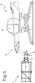
- the platform 1 comprises, solidly constrained to the mobile side wall 11, an elongate profiled member 51, for example an elongate curved plate, while the bottom of the platform 1 includes a sensor 52 for detecting the displacement of the profiled member, for example a switch (see figures 3 and 4 ).
- the curved plate 51 is fixed to the external side of the mobile side wall 11 while the sensor 52 is located below the bottom 10.
- the switch 52 When the mobile side wall 11 moves into the lowered position, the switch 52 is activated and produces a signal representing the fact that the platform 1 is in the open configuration.
- the detecting device includes a proximity sensor or in which the microswitch 52 is activated by a mechanism, linkage or mechanical member that is different to the above-mentioned plate 51.
- the system of the invention comprises a second command apparatus, separate from the platform 1 and adapted to enable an operator to select commands, and able to command the above-mentioned activating apparatus according to commands selected by the operator.
- the second apparatus can be the one located internally of the guide cabin 23 of the work machine 2 and can be like those already used in this type of vehicles and, for this reason, it is not illustrated in the appended figures.
- the second apparatus can be located externally of the vehicle; for example, the second apparatus can be provided with a radio remote control activatable by an operator from outside the cabin 23 of the machine 2.
- the second command apparatus like the above-described first apparatus, also comprises an interface, which can include a joystick, buttons, display (including a touchscreen), levers and the like, the activation of which enables the operator to select the commands for movement of the arm 21.
- an interface which can include a joystick, buttons, display (including a touchscreen), levers and the like, the activation of which enables the operator to select the commands for movement of the arm 21.
- control is provided with the interface as described in the foregoing paragraph.
- the interface of the second command apparatus is configured to enable to set or select at least one second position parameter, representative of the movement of the arm 21 both relative to the inclination with respect to the machine frame 2 and relative to the extension and shortening of the arm 21 and, possibly, relative to the rotation of the turret, if present.
- the second apparatus is adapted to generate second command signals, according to the selections made on the relative interface, and the above-mentioned processing unit is adapted to receive the second command signals and is configured to generate and transmit driving signals to the distributors, according to the second command signals received.
- the invention advantageously enables switching the command of the command apparatus 41 of the platform 1 to the operator in the cabin 23 and vice versa, according to the various working conditions and the different uses of the platform 1, with the aim of always maintaining the highest degree of safety and effectiveness of use.
- the system of the invention includes at least an enabling device 42, 43 provided with an interface selectable by an operator 31, 32 located on-board the platform 1.
- the invention preferably includes two enabling devices 42, 43 and, in general, might include a number of enabling devices 42, 43 matching the number of operators 31, 32 that are to work on-board the platform 1.
- the two enabling devices 42, 43 are separated from one another by a distance such as to prevent a same operator 31, 32 from selecting both interfaces of the devices 42, 43; in this way, it is guaranteed that the two operators 31, 32 required for working on-board the platform 1 both act voluntarily on the interface, with the aim of determining which one has command of the arm 21.
- the two devices 41, 42 are located at two internal corners of the platform 1, in particular the corners defined at the lateral ends of the side wall 12 opposite the mobile side wall; however, this is not a mandatory solution.
- the interface of the two enabling devices 42, 43 can also comprise common command elements such as buttons, displays, touchscreens, levers, etc...; in the example illustrated in the appended tables of drawings, each enabling device 42, 43 is provided with two buttons 421, 422, 431, 432, the use of which in the invention will be explained in detail in the following.
- the invention includes a processing unit, connected to the first 41 and second command apparatus and to the enabling device(s) 42, 43, as well as to the detecting device 51, 52.
- processing unit is presented divided into distinct functional modules for the sole purpose of describing the functions thereof in a clear and complete manner.
- the processing unit can be constituted by a single electronic device, including of the type commonly present on this type of machine and platforms, such as the two above-mentioned control units, suitably programmed for carrying out the functions described.
- the different modules can be hardware items and/or software routines that are part of the programmed device.
- the processing unit can use one or more microprocessors or microcontrollers for running the instructions contained in memory modules and the aforesaid functional modules may, also, be distributed over a plurality of local or remote computers based on the architecture of the network in which they reside.
- the processing unit is configured for enabling or disabling the command of the activating apparatus by the first 41 or the second command apparatus, according to the selections made on said interface of the enabling device(s) 42, 43.
- Selections of the interface also refers to the choice not to act on the interface; in detail, if the enabling devices 42, 43 are provided with buttons 421, 422, 431, 432 and they are not pressed, then a normal operating condition is selected.
- the processing unit comprises an enabling module configured for enabling control of the hydraulic distributors activating the arm 21 alternatively by the command apparatus 41 on-board the platform 1 or by the command apparatus in the cabin, according to what has been selected or not selected on the enabling devices 42, 43.
- an aim of the system of the invention is to allow that, during the use of the platform 1 for special activities such as removal of a cladding (for example an asbestos cladding), command of the movement of the arm 21, and therefore the displacing of the platform 1, is entrusted to the operator in the cabin and not the operators 31, 32 on the platform 1.
- the arm is commanded by the apparatus located on-board the platform, as the operators on the platform have direct vision of the environment surrounding the platform itself, for example the roof of a building, which the operator in the cabin does not have.
- the invention can also include the possibility of an exceptional operating condition in which the command of the arm 21 can be taken over by the operators 31, 32 on-board the platform 1, as is more fully explained in the following.
- the processing unit and in particular the enabling module thereof is configured either to enable or disable the command of the activating apparatus by the first 41 or the second command apparatus, also according to the checks carried out by the detecting device 51, 52, i.e. depending on whether the platform 1 is in the normal configuration or in the special use configuration.
- the processing unit receives the above-described first or second command signals, the configuration signals from the switch 52 (or other device suitable for the purpose) and enabling signals from the enabling devices 42, 43 and, according to these, processes driving signals which are transmitted to the distributor(s) which activate the cylinders of the arm 21.
- each enabling device 42, 43 includes buttons 421, 422, 431, 432, preferably two in number.
- Pressing on a first button 421, 431 selects a first enabling condition while pressing on the second button 422, 432 selects a second enabling condition, alternative to the first; in practice, on the basis of the pressure exerted on the buttons of the enabling devices 42, 43 the command of the arm 21 can be established or switched by the command apparatus 41 of the platform 1 or by the command apparatus separate from the platform 1 and located in the cabin 23.
- the invention envisages that the processing unit enables control of the arm 21 by the apparatus in the cabin, disabling the apparatus on the platform 1, if both the platform 31, 32 operators have contemporaneously pressed or continue to press the first button 421, 431 of the relative enabling device 42, 43.
- the interface of the enabling device 42, 43 is adapted to enable an operator 31, 32 to select at least a first enabling condition; when said first enabling condition is selected, the enabling module of the processing unit enables the second command apparatus (separate from the platform 1) to command the activating apparatus (constituted by one or more distributors) and at the same time disables the first command apparatus 41.
- the enabling module is configured to enable the second command apparatus to command the activating apparatus and to disable the first command apparatus 41, once said first enabling condition is selected in both the enabling devices 42, 43 located on-board the platform 1.
- the enabling module is preferably configured for enabling the first command apparatus 41 to command the activating apparatus, only if the detecting device 51, 52 has checked that the platform 1 is in the second working configuration, i.e. the one for special use of the platform.
- the enabling module enables the first command apparatus 41 to command the activating apparatus while disabling the second command apparatus.
- the platform 1 of the invention can be used like any other platform.
- the command of the arm 21 is exclusively entrusted to the operators 31, 32 on-board the platform 1 who use the joystick and the buttons or other interface means of the above-mentioned first command apparatus 41.
- the platform 1 is to be employed for special uses, such as the removal of asbestos roof claddings, before use the platform 1 must be opened, i.e. the mobile side wall 11 must be tilted, creating a lengthened bottom plane 10, 110 at the base of the platform 1.
- the opening of the mobile side wall 11 activates the switch 52 which transmits the above-mentioned configuration signal to the processing unit, which thus receives the information that the platform 1 is in the working configuration for special uses.
- the operators 31, 32 represented in a stylised way in the figures, board the platform 1 and move to a respective enabling device 42, 43, in order for both of them to press the above-mentioned first button 421, 431, which selects the first enabling condition.
- the processing unit disables the use of the first command apparatus 41, authorising only the second command apparatus located in the cabin only to move the lifting arm 21 on activation of the distributor or the hydraulic distributors.
- the two operators 31, 32 can remove the claddings and bring them on-board the platform 1.
- the platform 1 of the invention further comprises two hooking rods 61, 62, preferably curved in a hook shape, to which it is possible to anchor retaining cables (not illustrated for the sake of clarity in the figures) connected to the suits or to a harness worn by the operator 31, 32 working on the platform 1.
- the rods 61, 62 are preferably located at the opposite corners flanking the fixed side wall 12 opposite the mobile side wall 11; the rods 61, 62 prolong the side walls 11, 12, 13, 14 from above and can be removably coupled to attachment members mounted on the side walls and maintained in position by special holes and split pins or like releasable joining means.
- rods 61, 62 can be blocked in various angular positions to facilitate use thereof.
- the operators 31, 32 newly approach the enabling devices 42, 43 and both press the first button 421, 431 to enable the operator in the cabin to return the platform 1 to the ground surface, together with the material to be unloaded.
- the platform 1 In a case in which the operators 31, 32 are at height and for some reason the cabin operator is not able to activate the arm 21, for example because he has left the cabin, it is possible for the platform 1 to be lowered and the two operators 31, 32 to the ground surface in the following way.
- One of the platform 1 operators 32 goes to one of the enabling devices 42, 43 and presses the second button 432, 422.
- the processing unit then authorises the first command apparatus 41 to control the movement of the arms 21, enabling the second operator 31 to manoeuvre the platform 1 to bring it and its occupant operators 31, 32 to the ground surface.
- processing unit interrupts the disabling of the use of the first command apparatus 41 as long as the second button 432, 422 continues to be pressed.
Landscapes
- Engineering & Computer Science (AREA)
- Structural Engineering (AREA)
- Life Sciences & Earth Sciences (AREA)
- Geology (AREA)
- Mechanical Engineering (AREA)
- Forklifts And Lifting Vehicles (AREA)
- Paper (AREA)
- Eye Examination Apparatus (AREA)
- Vehicle Body Suspensions (AREA)
Claims (13)
- Hubsystem für Arbeitsmaschinen (2), umfassend:eine Ladeplattform (1), geeignet zum Tragen von Bedienpersonen (31, 32) und/oder Werkzeugen;einen beweglichen Hubarm (21), auf dem die Plattform (1) montiert ist;zumindest eine Betätigungsvorrichtung zum Bewegen des Arms (21);zumindest eine erste Steuereinrichtung (41), die an Bord der Plattform (1) angeordnet und geeignet ist, einer Bedienperson (31, 32) die Auswahl von Steuerbefehlen zu ermöglichen, wobei die erste Vorrichtung (41) in der Lage ist, die Betätigungsvorrichtung gemäß den von der Bedienperson (31, 32) ausgewählten Steuerbefehlen anzusteuern;zumindest eine zweite Steuereinrichtung, die von der Plattform (1) getrennt angeordnet und geeignet ist, einer Bedienperson die Auswahl von Steuerbefehlen zu ermöglichen, und die in der Lage ist, die Betätigungsvorrichtung gemäß den von der Bedienperson ausgewählten Steuerbefehlen anzusteuern;zumindest eine Zustimmeinrichtung (42, 43), die eine Schnittstelle (421, 422, 431, 432) aufweist, an der eine Bedienperson (31, 32) eine Auswahl tätigen kann; undeine Verarbeitungseinheit, die dafür konfiguriert ist, die Ansteuerung der Betätigungsvorrichtung durch die erste (41) oder die zweite Steuereinrichtung freizugeben oder zu sperren, je nachdem, welche Auswahl an der Schnittstelle der Zustimmeinrichtung (42, 43) getätigt wurde; dadurch gekennzeichnet, dassdie Zustimmeinrichtung (42, 43) an Bord der Plattform (1) angeordnet ist;die Schnittstelle der Zustimmeinrichtung (42, 43) geeignet ist, einer Bedienperson (31, 32) die Auswahl zumindest einer ersten Freigabebedingung zu ermöglichen, wobei die Verarbeitungseinheit ein Freigabemodul umfasst, das dafür konfiguriert ist, die zweite Steuereinrichtung für die Ansteuerung der Betätigungsvorrichtung freizugeben und die erste Steuereinrichtung (41) zu sperren, wenn diese erste Freigabebedingung ausgewählt wurde.
- System nach dem vorhergehenden Anspruch, umfassend zumindest zwei Zustimmeinrichtungen (42, 43).
- System nach zumindest einem der vorhergehenden Ansprüche, wobei die Plattform (1) geeignet ist, von einer ersten zu einer zweiten Betriebskonfiguration zu wechseln und umgekehrt.
- System nach dem vorhergehenden Anspruch, wobei die Plattform (1) eine Bodenfläche (10) und mehrere Seitenwände (11, 12, 13, 14) umfasst, von denen zumindest eine Seitenwand (11) beweglich ist zwischen einer aufgerichteten Position, die eine erste Konfiguration des Normalbetriebs der Plattform (1) definiert, und einer abgesenkten Position, die eine zweite Konfiguration des speziellen Betriebs der Plattform (1) definiert.
- System nach dem vorhergehenden Anspruch, wobei die bewegliche Seitenwand (11) in ihrer abgesenkten Position eine Verlängerung der Bodenfläche (10) bildet.
- System nach zumindest einem der Ansprüche von 3 bis 5, umfassend zumindest eine Erkennungseinrichtung (51, 52) zur Prüfung, ob die Plattform (1) in der ersten oder der zweiten Betriebskonfiguration angeordnet ist, wobei die Verarbeitungseinheit dafür konfiguriert ist, die Ansteuerung der Betätigungsvorrichtung durch die erste (41) oder die zweite Steuereinrichtung freizugeben oder zu sperren, auch unter Berücksichtigung der durch die Erkennungseinrichtung (51, 52) vorgenommenen Prüfungen.
- System nach zumindest einem der Ansprüche von 4 bis 6, wobei die Erkennungseinrichtung (51, 52) geeignet ist zu prüfen, ob sich die bewegliche Seitenwand (11) in der aufgerichteten Position befindet, oder zu prüfen, ob sich die bewegliche Seitenwand (11) in der abgesenkten Position befindet, oder beides.
- System nach Anspruch 2, wobei das Freigabemodul dafür konfiguriert ist, die zweite Steuereinrichtung für die Ansteuerung der Betätigungsvorrichtung freizugeben und die erste Steuereinrichtung (41) zu sperren, nachdem die erste Freigabebedingung an beiden Zustimmeinrichtungen (42, 43) ausgewählt wurde.
- System nach zumindest einem der Ansprüche von 2 bis 8, wobei die zwei Zustimmeinrichtungen (42, 43) durch einen Abstand voneinander getrennt sind, der verhindert, dass dieselbe Bedienperson (31, 32) gleichzeitig eine Auswahl an beiden Schnittstellen der Einrichtungen (42, 43) tätigen kann.
- System nach zumindest einem der vorhergehenden Ansprüche, wobei die Schnittstelle der Zustimmeinrichtung (42, 43) geeignet ist, einer Bedienperson (31, 32) die Auswahl einer zweiten Freigabebedingung zu ermöglichen, wobei die Verarbeitungseinheit ein Freigabemodul umfasst, das dafür konfiguriert ist, die erste Steuereinrichtung (41) für die Ansteuerung der Betätigungsvorrichtung freizugeben und die zweite Steuereinrichtung zu sperren, wenn diese zweite Freigabebedingung ausgewählt wurde.
- System nach zumindest einem der Ansprüche von 6 bis 10, wobei das Freigabemodul dafür konfiguriert ist, die erste Steuereinrichtung (41) für die Ansteuerung der Betätigungsvorrichtung freizugeben, nachdem durch die Erkennungseinrichtung (51, 52) geprüft wurde, dass sich die Plattform (1) in der zweiten Betriebskonfiguration befindet.
- System nach zumindest einem der vorhergehenden Ansprüche, wobei die zweite Steuereinrichtung mit einer Funkfernsteuerung ausgestattet ist.
- Arbeitsmaschine (2), umfassend ein System nach zumindest einem der vorhergehenden Ansprüche und umfassend eine Kabine (23) in der die zweite Steuereinrichtung angeordnet ist.
Priority Applications (4)
| Application Number | Priority Date | Filing Date | Title |
|---|---|---|---|
| SM20200090T SMT202000090T1 (it) | 2017-04-06 | 2018-03-28 | Sistema di sollevamento |
| PL18165068T PL3392192T3 (pl) | 2017-04-06 | 2018-03-29 | Układ podnoszący |
| SI201830020T SI3392192T1 (sl) | 2017-04-06 | 2018-03-29 | Dvižni sistem |
| HRP20200071TT HRP20200071T1 (hr) | 2017-04-06 | 2020-01-17 | Sustav za podizanje |
Applications Claiming Priority (1)
| Application Number | Priority Date | Filing Date | Title |
|---|---|---|---|
| IT102017000038086A IT201700038086A1 (it) | 2017-04-06 | 2017-04-06 | Sistema di sollevamento. |
Publications (2)
| Publication Number | Publication Date |
|---|---|
| EP3392192A1 EP3392192A1 (de) | 2018-10-24 |
| EP3392192B1 true EP3392192B1 (de) | 2019-11-20 |
Family
ID=60020275
Family Applications (1)
| Application Number | Title | Priority Date | Filing Date |
|---|---|---|---|
| EP18165068.0A Active EP3392192B1 (de) | 2017-04-06 | 2018-03-29 | Hubsystem |
Country Status (10)
| Country | Link |
|---|---|
| EP (1) | EP3392192B1 (de) |
| DK (1) | DK3392192T3 (de) |
| ES (1) | ES2768101T3 (de) |
| HR (1) | HRP20200071T1 (de) |
| HU (1) | HUE047911T2 (de) |
| IT (1) | IT201700038086A1 (de) |
| PL (1) | PL3392192T3 (de) |
| PT (1) | PT3392192T (de) |
| SI (1) | SI3392192T1 (de) |
| SM (1) | SMT202000090T1 (de) |
Families Citing this family (5)
| Publication number | Priority date | Publication date | Assignee | Title |
|---|---|---|---|---|
| US12202715B2 (en) | 2020-01-16 | 2025-01-21 | Xtreme Manufacturing, Llc | Telehandler boom auxiliary control panel |
| US11919756B2 (en) * | 2020-02-04 | 2024-03-05 | Xtreme Manufacturing, Llc | Aerial work vehicle boom auxiliary control panel |
| CN111453661A (zh) * | 2020-04-14 | 2020-07-28 | 董科 | 一种助老助残的泳池移位装置 |
| IT202000015508A1 (it) | 2020-06-26 | 2021-12-26 | Manitou Italia Srl | Sistema di sollevamento per macchine operatrici. |
| EP4514738A4 (de) * | 2023-05-22 | 2026-01-21 | Orguel Ind E Locacao De Equipamentos S/A | Automatisierte teleskophebebühne |
Family Cites Families (5)
| Publication number | Priority date | Publication date | Assignee | Title |
|---|---|---|---|---|
| US5992562A (en) * | 1996-01-26 | 1999-11-30 | Jlg Industries, Inc. | Scissor lift control apparatus |
| SG82672A1 (en) * | 1999-02-04 | 2001-08-21 | Snorkel International Inc | Aerial work platform boom having ground and platform controls linked by a controller area network |
| US8016074B2 (en) * | 2008-12-03 | 2011-09-13 | Jlg Industries, Inc. | Work platform |
| US8651237B2 (en) * | 2010-06-09 | 2014-02-18 | Richard D Pulliam | Worker support cage for front end loader bucket |
| GB201011136D0 (en) * | 2010-07-02 | 2010-08-18 | Blue Sky Access Ltd | An aerial lift with safety device |
-
2017
- 2017-04-06 IT IT102017000038086A patent/IT201700038086A1/it unknown
-
2018
- 2018-03-28 SM SM20200090T patent/SMT202000090T1/it unknown
- 2018-03-29 DK DK18165068.0T patent/DK3392192T3/da active
- 2018-03-29 PT PT181650680T patent/PT3392192T/pt unknown
- 2018-03-29 ES ES18165068T patent/ES2768101T3/es active Active
- 2018-03-29 HU HUE18165068A patent/HUE047911T2/hu unknown
- 2018-03-29 PL PL18165068T patent/PL3392192T3/pl unknown
- 2018-03-29 EP EP18165068.0A patent/EP3392192B1/de active Active
- 2018-03-29 SI SI201830020T patent/SI3392192T1/sl unknown
-
2020
- 2020-01-17 HR HRP20200071TT patent/HRP20200071T1/hr unknown
Non-Patent Citations (1)
| Title |
|---|
| None * |
Also Published As
| Publication number | Publication date |
|---|---|
| PL3392192T3 (pl) | 2020-06-29 |
| IT201700038086A1 (it) | 2018-10-06 |
| EP3392192A1 (de) | 2018-10-24 |
| SI3392192T1 (sl) | 2020-02-28 |
| PT3392192T (pt) | 2020-02-25 |
| HRP20200071T1 (hr) | 2020-04-03 |
| SMT202000090T1 (it) | 2020-03-13 |
| ES2768101T3 (es) | 2020-06-19 |
| DK3392192T3 (da) | 2020-02-24 |
| HUE047911T2 (hu) | 2020-05-28 |
Similar Documents
| Publication | Publication Date | Title |
|---|---|---|
| EP3392192B1 (de) | Hubsystem | |
| US20220203146A1 (en) | Personal safety apparatus and system | |
| US11565922B2 (en) | Remote controlled telehandler | |
| US9568939B2 (en) | Tactile feedback for joystick position/speed controls | |
| EP3412619B1 (de) | Fernbetriebsendgerät und system zum fernbetrieb eines mobilen krans | |
| US9567193B2 (en) | Method for controlling a load-moving device and controller of a load-moving device | |
| US20200180916A1 (en) | Safety system for self-propelled operating machines | |
| CN104098053B (zh) | 架空系统,特别是转台云梯系统 | |
| US20100302017A1 (en) | Tactile Feedback for Joystick Position/Speed Controls | |
| EP3851409B1 (de) | Hilfssteuerungstafel für teleskopladerausleger | |
| CN106061885A (zh) | 起重机控制装置 | |
| US9290955B2 (en) | Working device with stationary mast and rotary head | |
| JP7256687B2 (ja) | 杭打機の安全システム | |
| US20210238021A1 (en) | Aerial work vehicle auxiliary wireless control device | |
| US6170606B1 (en) | Analog control | |
| CN113845069A (zh) | 用于操作机械的提升系统 | |
| EP3862311B1 (de) | Hilfssteuertafel für den ausleger eines hubarbeitsfahrzeugs | |
| EP4067292A1 (de) | Drahtlose hilfssteuerungsvorrichtung eines luftarbeitsfahrzeugs | |
| WO2017183576A1 (ja) | 移動式クレーンの緊急停止装置 | |
| JPH0743120Y2 (ja) | 高所作業車 | |
| EP3658484B1 (de) | Stabilisierungssystem für selbstfahrende arbeitsmaschinen | |
| JP3528161B2 (ja) | スタッカクレーン | |
| JP2003128396A (ja) | 高所作業車の操作信号伝送システム | |
| NO311345B1 (no) | Bomanordning |
Legal Events
| Date | Code | Title | Description |
|---|---|---|---|
| PUAI | Public reference made under article 153(3) epc to a published international application that has entered the european phase |
Free format text: ORIGINAL CODE: 0009012 |
|
| STAA | Information on the status of an ep patent application or granted ep patent |
Free format text: STATUS: THE APPLICATION HAS BEEN PUBLISHED |
|
| AK | Designated contracting states |
Kind code of ref document: A1 Designated state(s): AL AT BE BG CH CY CZ DE DK EE ES FI FR GB GR HR HU IE IS IT LI LT LU LV MC MK MT NL NO PL PT RO RS SE SI SK SM TR |
|
| AX | Request for extension of the european patent |
Extension state: BA ME |
|
| STAA | Information on the status of an ep patent application or granted ep patent |
Free format text: STATUS: REQUEST FOR EXAMINATION WAS MADE |
|
| 17P | Request for examination filed |
Effective date: 20190423 |
|
| RBV | Designated contracting states (corrected) |
Designated state(s): AL AT BE BG CH CY CZ DE DK EE ES FI FR GB GR HR HU IE IS IT LI LT LU LV MC MK MT NL NO PL PT RO RS SE SI SK SM TR |
|
| RIC1 | Information provided on ipc code assigned before grant |
Ipc: B66F 17/00 20060101ALI20190628BHEP Ipc: B66F 11/04 20060101AFI20190628BHEP |
|
| GRAP | Despatch of communication of intention to grant a patent |
Free format text: ORIGINAL CODE: EPIDOSNIGR1 |
|
| STAA | Information on the status of an ep patent application or granted ep patent |
Free format text: STATUS: GRANT OF PATENT IS INTENDED |
|
| INTG | Intention to grant announced |
Effective date: 20190814 |
|
| GRAS | Grant fee paid |
Free format text: ORIGINAL CODE: EPIDOSNIGR3 |
|
| GRAA | (expected) grant |
Free format text: ORIGINAL CODE: 0009210 |
|
| STAA | Information on the status of an ep patent application or granted ep patent |
Free format text: STATUS: THE PATENT HAS BEEN GRANTED |
|
| AK | Designated contracting states |
Kind code of ref document: B1 Designated state(s): AL AT BE BG CH CY CZ DE DK EE ES FI FR GB GR HR HU IE IS IT LI LT LU LV MC MK MT NL NO PL PT RO RS SE SI SK SM TR |
|
| REG | Reference to a national code |
Ref country code: GB Ref legal event code: FG4D |
|
| REG | Reference to a national code |
Ref country code: CH Ref legal event code: EP |
|
| REG | Reference to a national code |
Ref country code: IE Ref legal event code: FG4D |
|
| REG | Reference to a national code |
Ref country code: DE Ref legal event code: R096 Ref document number: 602018001227 Country of ref document: DE |
|
| REG | Reference to a national code |
Ref country code: AT Ref legal event code: REF Ref document number: 1203986 Country of ref document: AT Kind code of ref document: T Effective date: 20191215 |
|
| REG | Reference to a national code |
Ref country code: HR Ref legal event code: TUEP Ref document number: P20200071T Country of ref document: HR |
|
| REG | Reference to a national code |
Ref country code: FI Ref legal event code: FGE |
|
| REG | Reference to a national code |
Ref country code: CH Ref legal event code: NV Representative=s name: BUGNION S.A., CH |
|
| REG | Reference to a national code |
Ref country code: DK Ref legal event code: T3 Effective date: 20200219 |
|
| REG | Reference to a national code |
Ref country code: PT Ref legal event code: SC4A Ref document number: 3392192 Country of ref document: PT Date of ref document: 20200225 Kind code of ref document: T Free format text: AVAILABILITY OF NATIONAL TRANSLATION Effective date: 20200213 |
|
| REG | Reference to a national code |
Ref country code: NL Ref legal event code: FP |
|
| REG | Reference to a national code |
Ref country code: SE Ref legal event code: TRGR |
|
| REG | Reference to a national code |
Ref country code: NO Ref legal event code: T2 Effective date: 20191120 |
|
| REG | Reference to a national code |
Ref country code: HR Ref legal event code: T1PR Ref document number: P20200071 Country of ref document: HR |
|
| REG | Reference to a national code |
Ref country code: LT Ref legal event code: MG4D |
|
| REG | Reference to a national code |
Ref country code: GR Ref legal event code: EP Ref document number: 20200400175 Country of ref document: GR Effective date: 20200415 |
|
| PG25 | Lapsed in a contracting state [announced via postgrant information from national office to epo] |
Ref country code: LV Free format text: LAPSE BECAUSE OF FAILURE TO SUBMIT A TRANSLATION OF THE DESCRIPTION OR TO PAY THE FEE WITHIN THE PRESCRIBED TIME-LIMIT Effective date: 20191120 Ref country code: LT Free format text: LAPSE BECAUSE OF FAILURE TO SUBMIT A TRANSLATION OF THE DESCRIPTION OR TO PAY THE FEE WITHIN THE PRESCRIBED TIME-LIMIT Effective date: 20191120 |
|
| REG | Reference to a national code |
Ref country code: HR Ref legal event code: ODRP Ref document number: P20200071 Country of ref document: HR Payment date: 20200326 Year of fee payment: 3 |
|
| REG | Reference to a national code |
Ref country code: HU Ref legal event code: AG4A Ref document number: E047911 Country of ref document: HU |
|
| PG25 | Lapsed in a contracting state [announced via postgrant information from national office to epo] |
Ref country code: RS Free format text: LAPSE BECAUSE OF FAILURE TO SUBMIT A TRANSLATION OF THE DESCRIPTION OR TO PAY THE FEE WITHIN THE PRESCRIBED TIME-LIMIT Effective date: 20191120 |
|
| REG | Reference to a national code |
Ref country code: ES Ref legal event code: FG2A Ref document number: 2768101 Country of ref document: ES Kind code of ref document: T3 Effective date: 20200619 |
|
| PG25 | Lapsed in a contracting state [announced via postgrant information from national office to epo] |
Ref country code: AL Free format text: LAPSE BECAUSE OF FAILURE TO SUBMIT A TRANSLATION OF THE DESCRIPTION OR TO PAY THE FEE WITHIN THE PRESCRIBED TIME-LIMIT Effective date: 20191120 |
|
| PG25 | Lapsed in a contracting state [announced via postgrant information from national office to epo] |
Ref country code: RO Free format text: LAPSE BECAUSE OF FAILURE TO SUBMIT A TRANSLATION OF THE DESCRIPTION OR TO PAY THE FEE WITHIN THE PRESCRIBED TIME-LIMIT Effective date: 20191120 Ref country code: EE Free format text: LAPSE BECAUSE OF FAILURE TO SUBMIT A TRANSLATION OF THE DESCRIPTION OR TO PAY THE FEE WITHIN THE PRESCRIBED TIME-LIMIT Effective date: 20191120 |
|
| REG | Reference to a national code |
Ref country code: DE Ref legal event code: R097 Ref document number: 602018001227 Country of ref document: DE |
|
| PG25 | Lapsed in a contracting state [announced via postgrant information from national office to epo] |
Ref country code: SK Free format text: LAPSE BECAUSE OF FAILURE TO SUBMIT A TRANSLATION OF THE DESCRIPTION OR TO PAY THE FEE WITHIN THE PRESCRIBED TIME-LIMIT Effective date: 20191120 |
|
| PLBE | No opposition filed within time limit |
Free format text: ORIGINAL CODE: 0009261 |
|
| STAA | Information on the status of an ep patent application or granted ep patent |
Free format text: STATUS: NO OPPOSITION FILED WITHIN TIME LIMIT |
|
| 26N | No opposition filed |
Effective date: 20200821 |
|
| PG25 | Lapsed in a contracting state [announced via postgrant information from national office to epo] |
Ref country code: GR Free format text: LAPSE BECAUSE OF NON-PAYMENT OF DUE FEES Effective date: 20201008 |
|
| REG | Reference to a national code |
Ref country code: HR Ref legal event code: ODRP Ref document number: P20200071 Country of ref document: HR Payment date: 20210309 Year of fee payment: 4 |
|
| REG | Reference to a national code |
Ref country code: AT Ref legal event code: UEP Ref document number: 1203986 Country of ref document: AT Kind code of ref document: T Effective date: 20191120 |
|
| REG | Reference to a national code |
Ref country code: HR Ref legal event code: ODRP Ref document number: P20200071 Country of ref document: HR Payment date: 20220310 Year of fee payment: 5 |
|
| PG25 | Lapsed in a contracting state [announced via postgrant information from national office to epo] |
Ref country code: MT Free format text: LAPSE BECAUSE OF FAILURE TO SUBMIT A TRANSLATION OF THE DESCRIPTION OR TO PAY THE FEE WITHIN THE PRESCRIBED TIME-LIMIT Effective date: 20191120 Ref country code: CY Free format text: LAPSE BECAUSE OF FAILURE TO SUBMIT A TRANSLATION OF THE DESCRIPTION OR TO PAY THE FEE WITHIN THE PRESCRIBED TIME-LIMIT Effective date: 20191120 |
|
| PG25 | Lapsed in a contracting state [announced via postgrant information from national office to epo] |
Ref country code: MK Free format text: LAPSE BECAUSE OF FAILURE TO SUBMIT A TRANSLATION OF THE DESCRIPTION OR TO PAY THE FEE WITHIN THE PRESCRIBED TIME-LIMIT Effective date: 20191120 |
|
| REG | Reference to a national code |
Ref country code: HR Ref legal event code: ODRP Ref document number: P20200071 Country of ref document: HR Payment date: 20230320 Year of fee payment: 6 |
|
| P01 | Opt-out of the competence of the unified patent court (upc) registered |
Effective date: 20230526 |
|
| REG | Reference to a national code |
Ref country code: HR Ref legal event code: ODRP Ref document number: P20200071 Country of ref document: HR Payment date: 20240308 Year of fee payment: 7 |
|
| REG | Reference to a national code |
Ref country code: HR Ref legal event code: ODRP Ref document number: P20200071 Country of ref document: HR Payment date: 20250311 Year of fee payment: 8 |
|
| PGFP | Annual fee paid to national office [announced via postgrant information from national office to epo] |
Ref country code: BG Payment date: 20250326 Year of fee payment: 8 |
|
| PGFP | Annual fee paid to national office [announced via postgrant information from national office to epo] |
Ref country code: SI Payment date: 20250313 Year of fee payment: 8 |
|
| PGFP | Annual fee paid to national office [announced via postgrant information from national office to epo] |
Ref country code: ES Payment date: 20250423 Year of fee payment: 8 |
|
| PGFP | Annual fee paid to national office [announced via postgrant information from national office to epo] |
Ref country code: IT Payment date: 20250327 Year of fee payment: 8 |
|
| PGFP | Annual fee paid to national office [announced via postgrant information from national office to epo] |
Ref country code: CH Payment date: 20250401 Year of fee payment: 8 |
|
| REG | Reference to a national code |
Ref country code: CH Ref legal event code: U11 Free format text: ST27 STATUS EVENT CODE: U-0-0-U10-U11 (AS PROVIDED BY THE NATIONAL OFFICE) Effective date: 20260401 |
|
| PGFP | Annual fee paid to national office [announced via postgrant information from national office to epo] |
Ref country code: SM Payment date: 20260225 Year of fee payment: 9 |
|
| PGFP | Annual fee paid to national office [announced via postgrant information from national office to epo] |
Ref country code: SE Payment date: 20260323 Year of fee payment: 9 |
|
| PGFP | Annual fee paid to national office [announced via postgrant information from national office to epo] |
Ref country code: GB Payment date: 20260304 Year of fee payment: 9 |
|
| PGFP | Annual fee paid to national office [announced via postgrant information from national office to epo] |
Ref country code: MC Payment date: 20260320 Year of fee payment: 9 |
|
| REG | Reference to a national code |
Ref country code: HR Ref legal event code: ODRP Ref document number: P20200071 Country of ref document: HR Payment date: 20260309 Year of fee payment: 9 |
|
| PGFP | Annual fee paid to national office [announced via postgrant information from national office to epo] |
Ref country code: NO Payment date: 20260318 Year of fee payment: 9 Ref country code: DE Payment date: 20260320 Year of fee payment: 9 Ref country code: IE Payment date: 20260318 Year of fee payment: 9 Ref country code: DK Payment date: 20260323 Year of fee payment: 9 |
|
| PGFP | Annual fee paid to national office [announced via postgrant information from national office to epo] |
Ref country code: AT Payment date: 20260318 Year of fee payment: 9 Ref country code: HR Payment date: 20260309 Year of fee payment: 9 |
|
| PGFP | Annual fee paid to national office [announced via postgrant information from national office to epo] |
Ref country code: FI Payment date: 20260323 Year of fee payment: 9 Ref country code: LU Payment date: 20260323 Year of fee payment: 9 Ref country code: BE Payment date: 20260323 Year of fee payment: 9 |
|
| PGFP | Annual fee paid to national office [announced via postgrant information from national office to epo] |
Ref country code: HU Payment date: 20260325 Year of fee payment: 9 Ref country code: NL Payment date: 20260323 Year of fee payment: 9 |
|
| PGFP | Annual fee paid to national office [announced via postgrant information from national office to epo] |
Ref country code: IS Payment date: 20260328 Year of fee payment: 9 Ref country code: FR Payment date: 20260323 Year of fee payment: 9 |
|
| PGFP | Annual fee paid to national office [announced via postgrant information from national office to epo] |
Ref country code: TR Payment date: 20260312 Year of fee payment: 9 |
|
| PGFP | Annual fee paid to national office [announced via postgrant information from national office to epo] |
Ref country code: PT Payment date: 20260309 Year of fee payment: 9 Ref country code: CZ Payment date: 20260320 Year of fee payment: 9 |
|
| PGFP | Annual fee paid to national office [announced via postgrant information from national office to epo] |
Ref country code: PL Payment date: 20260305 Year of fee payment: 9 |