EP3392196B1 - Système de production d'hydrogène - Google Patents
Système de production d'hydrogène Download PDFInfo
- Publication number
- EP3392196B1 EP3392196B1 EP18167130.6A EP18167130A EP3392196B1 EP 3392196 B1 EP3392196 B1 EP 3392196B1 EP 18167130 A EP18167130 A EP 18167130A EP 3392196 B1 EP3392196 B1 EP 3392196B1
- Authority
- EP
- European Patent Office
- Prior art keywords
- reformer
- reactor
- hydrogen production
- production system
- lattice
- Prior art date
- Legal status (The legal status is an assumption and is not a legal conclusion. Google has not performed a legal analysis and makes no representation as to the accuracy of the status listed.)
- Active
Links
Images


Classifications
-
- H—ELECTRICITY
- H01—ELECTRIC ELEMENTS
- H01M—PROCESSES OR MEANS, e.g. BATTERIES, FOR THE DIRECT CONVERSION OF CHEMICAL ENERGY INTO ELECTRICAL ENERGY
- H01M8/00—Fuel cells; Manufacture thereof
- H01M8/06—Combination of fuel cells with means for production of reactants or for treatment of residues
- H01M8/0606—Combination of fuel cells with means for production of reactants or for treatment of residues with means for production of gaseous reactants
- H01M8/0612—Combination of fuel cells with means for production of reactants or for treatment of residues with means for production of gaseous reactants from carbon-containing material
- H01M8/0618—Reforming processes, e.g. autothermal, partial oxidation or steam reforming
-
- B—PERFORMING OPERATIONS; TRANSPORTING
- B01—PHYSICAL OR CHEMICAL PROCESSES OR APPARATUS IN GENERAL
- B01J—CHEMICAL OR PHYSICAL PROCESSES, e.g. CATALYSIS OR COLLOID CHEMISTRY; THEIR RELEVANT APPARATUS
- B01J19/00—Chemical, physical or physico-chemical processes in general; Their relevant apparatus
- B01J19/24—Stationary reactors without moving elements inside
- B01J19/2415—Tubular reactors
- B01J19/242—Tubular reactors in series
-
- B—PERFORMING OPERATIONS; TRANSPORTING
- B01—PHYSICAL OR CHEMICAL PROCESSES OR APPARATUS IN GENERAL
- B01J—CHEMICAL OR PHYSICAL PROCESSES, e.g. CATALYSIS OR COLLOID CHEMISTRY; THEIR RELEVANT APPARATUS
- B01J19/00—Chemical, physical or physico-chemical processes in general; Their relevant apparatus
- B01J19/24—Stationary reactors without moving elements inside
- B01J19/2445—Stationary reactors without moving elements inside placed in parallel
-
- B—PERFORMING OPERATIONS; TRANSPORTING
- B01—PHYSICAL OR CHEMICAL PROCESSES OR APPARATUS IN GENERAL
- B01J—CHEMICAL OR PHYSICAL PROCESSES, e.g. CATALYSIS OR COLLOID CHEMISTRY; THEIR RELEVANT APPARATUS
- B01J19/00—Chemical, physical or physico-chemical processes in general; Their relevant apparatus
- B01J19/24—Stationary reactors without moving elements inside
- B01J19/245—Stationary reactors without moving elements inside placed in series
-
- B—PERFORMING OPERATIONS; TRANSPORTING
- B01—PHYSICAL OR CHEMICAL PROCESSES OR APPARATUS IN GENERAL
- B01J—CHEMICAL OR PHYSICAL PROCESSES, e.g. CATALYSIS OR COLLOID CHEMISTRY; THEIR RELEVANT APPARATUS
- B01J19/00—Chemical, physical or physico-chemical processes in general; Their relevant apparatus
- B01J19/24—Stationary reactors without moving elements inside
- B01J19/248—Reactors comprising multiple separated flow channels
-
- B—PERFORMING OPERATIONS; TRANSPORTING
- B01—PHYSICAL OR CHEMICAL PROCESSES OR APPARATUS IN GENERAL
- B01J—CHEMICAL OR PHYSICAL PROCESSES, e.g. CATALYSIS OR COLLOID CHEMISTRY; THEIR RELEVANT APPARATUS
- B01J8/00—Chemical or physical processes in general, conducted in the presence of fluids and solid particles; Apparatus for such processes
- B01J8/02—Chemical or physical processes in general, conducted in the presence of fluids and solid particles; Apparatus for such processes with stationary particles, e.g. in fixed beds
- B01J8/04—Chemical or physical processes in general, conducted in the presence of fluids and solid particles; Apparatus for such processes with stationary particles, e.g. in fixed beds the fluid passing successively through two or more beds
-
- C—CHEMISTRY; METALLURGY
- C01—INORGANIC CHEMISTRY
- C01B—NON-METALLIC ELEMENTS; COMPOUNDS THEREOF; METALLOIDS OR COMPOUNDS THEREOF NOT COVERED BY SUBCLASS C01C
- C01B3/00—Hydrogen; Gaseous mixtures containing hydrogen; Separation of hydrogen from mixtures containing it; Purification of hydrogen; Reversible storage of hydrogen
- C01B3/02—Production of hydrogen; Production of gaseous mixtures containing hydrogen
- C01B3/32—Production of hydrogen; Production of gaseous mixtures containing hydrogen by reaction of gaseous or liquid organic compounds with gasifying agents, e.g. water, carbon dioxide or air
- C01B3/34—Production of hydrogen; Production of gaseous mixtures containing hydrogen by reaction of gaseous or liquid organic compounds with gasifying agents, e.g. water, carbon dioxide or air by reaction of hydrocarbons with gasifying agents
- C01B3/38—Production of hydrogen; Production of gaseous mixtures containing hydrogen by reaction of gaseous or liquid organic compounds with gasifying agents, e.g. water, carbon dioxide or air by reaction of hydrocarbons with gasifying agents using catalysts
- C01B3/384—Production of hydrogen; Production of gaseous mixtures containing hydrogen by reaction of gaseous or liquid organic compounds with gasifying agents, e.g. water, carbon dioxide or air by reaction of hydrocarbons with gasifying agents using catalysts with external heating of the catalyst
-
- C—CHEMISTRY; METALLURGY
- C01—INORGANIC CHEMISTRY
- C01B—NON-METALLIC ELEMENTS; COMPOUNDS THEREOF; METALLOIDS OR COMPOUNDS THEREOF NOT COVERED BY SUBCLASS C01C
- C01B3/00—Hydrogen; Gaseous mixtures containing hydrogen; Separation of hydrogen from mixtures containing it; Purification of hydrogen; Reversible storage of hydrogen
- C01B3/02—Production of hydrogen; Production of gaseous mixtures containing hydrogen
- C01B3/32—Production of hydrogen; Production of gaseous mixtures containing hydrogen by reaction of gaseous or liquid organic compounds with gasifying agents, e.g. water, carbon dioxide or air
- C01B3/34—Production of hydrogen; Production of gaseous mixtures containing hydrogen by reaction of gaseous or liquid organic compounds with gasifying agents, e.g. water, carbon dioxide or air by reaction of hydrocarbons with gasifying agents
- C01B3/48—Production of hydrogen; Production of gaseous mixtures containing hydrogen by reaction of gaseous or liquid organic compounds with gasifying agents, e.g. water, carbon dioxide or air by reaction of hydrocarbons with gasifying agents followed by reaction of water vapour with carbon monoxide
-
- H—ELECTRICITY
- H01—ELECTRIC ELEMENTS
- H01M—PROCESSES OR MEANS, e.g. BATTERIES, FOR THE DIRECT CONVERSION OF CHEMICAL ENERGY INTO ELECTRICAL ENERGY
- H01M8/00—Fuel cells; Manufacture thereof
- H01M8/06—Combination of fuel cells with means for production of reactants or for treatment of residues
- H01M8/0662—Treatment of gaseous reactants or gaseous residues, e.g. cleaning
- H01M8/0675—Removal of sulfur
-
- B—PERFORMING OPERATIONS; TRANSPORTING
- B01—PHYSICAL OR CHEMICAL PROCESSES OR APPARATUS IN GENERAL
- B01J—CHEMICAL OR PHYSICAL PROCESSES, e.g. CATALYSIS OR COLLOID CHEMISTRY; THEIR RELEVANT APPARATUS
- B01J2219/00—Chemical, physical or physico-chemical processes in general; Their relevant apparatus
- B01J2219/00002—Chemical plants
- B01J2219/00018—Construction aspects
- B01J2219/0002—Plants assembled from modules joined together
-
- B—PERFORMING OPERATIONS; TRANSPORTING
- B01—PHYSICAL OR CHEMICAL PROCESSES OR APPARATUS IN GENERAL
- B01J—CHEMICAL OR PHYSICAL PROCESSES, e.g. CATALYSIS OR COLLOID CHEMISTRY; THEIR RELEVANT APPARATUS
- B01J2219/00—Chemical, physical or physico-chemical processes in general; Their relevant apparatus
- B01J2219/24—Stationary reactors without moving elements inside
- B01J2219/2401—Reactors comprising multiple separate flow channels
-
- C—CHEMISTRY; METALLURGY
- C01—INORGANIC CHEMISTRY
- C01B—NON-METALLIC ELEMENTS; COMPOUNDS THEREOF; METALLOIDS OR COMPOUNDS THEREOF NOT COVERED BY SUBCLASS C01C
- C01B2203/00—Integrated processes for the production of hydrogen or synthesis gas
- C01B2203/02—Processes for making hydrogen or synthesis gas
- C01B2203/0205—Processes for making hydrogen or synthesis gas containing a reforming step
- C01B2203/0227—Processes for making hydrogen or synthesis gas containing a reforming step containing a catalytic reforming step
-
- C—CHEMISTRY; METALLURGY
- C01—INORGANIC CHEMISTRY
- C01B—NON-METALLIC ELEMENTS; COMPOUNDS THEREOF; METALLOIDS OR COMPOUNDS THEREOF NOT COVERED BY SUBCLASS C01C
- C01B2203/00—Integrated processes for the production of hydrogen or synthesis gas
- C01B2203/02—Processes for making hydrogen or synthesis gas
- C01B2203/0205—Processes for making hydrogen or synthesis gas containing a reforming step
- C01B2203/0227—Processes for making hydrogen or synthesis gas containing a reforming step containing a catalytic reforming step
- C01B2203/0233—Processes for making hydrogen or synthesis gas containing a reforming step containing a catalytic reforming step the reforming step being a steam reforming step
-
- C—CHEMISTRY; METALLURGY
- C01—INORGANIC CHEMISTRY
- C01B—NON-METALLIC ELEMENTS; COMPOUNDS THEREOF; METALLOIDS OR COMPOUNDS THEREOF NOT COVERED BY SUBCLASS C01C
- C01B2203/00—Integrated processes for the production of hydrogen or synthesis gas
- C01B2203/02—Processes for making hydrogen or synthesis gas
- C01B2203/0283—Processes for making hydrogen or synthesis gas containing a CO-shift step, i.e. a water gas shift step
-
- C—CHEMISTRY; METALLURGY
- C01—INORGANIC CHEMISTRY
- C01B—NON-METALLIC ELEMENTS; COMPOUNDS THEREOF; METALLOIDS OR COMPOUNDS THEREOF NOT COVERED BY SUBCLASS C01C
- C01B2203/00—Integrated processes for the production of hydrogen or synthesis gas
- C01B2203/06—Integration with other chemical processes
- C01B2203/066—Integration with other chemical processes with fuel cells
-
- C—CHEMISTRY; METALLURGY
- C01—INORGANIC CHEMISTRY
- C01B—NON-METALLIC ELEMENTS; COMPOUNDS THEREOF; METALLOIDS OR COMPOUNDS THEREOF NOT COVERED BY SUBCLASS C01C
- C01B2203/00—Integrated processes for the production of hydrogen or synthesis gas
- C01B2203/08—Methods of heating or cooling
- C01B2203/0805—Methods of heating the process for making hydrogen or synthesis gas
- C01B2203/0811—Methods of heating the process for making hydrogen or synthesis gas by combustion of fuel
-
- C—CHEMISTRY; METALLURGY
- C01—INORGANIC CHEMISTRY
- C01B—NON-METALLIC ELEMENTS; COMPOUNDS THEREOF; METALLOIDS OR COMPOUNDS THEREOF NOT COVERED BY SUBCLASS C01C
- C01B2203/00—Integrated processes for the production of hydrogen or synthesis gas
- C01B2203/08—Methods of heating or cooling
- C01B2203/0805—Methods of heating the process for making hydrogen or synthesis gas
- C01B2203/0833—Heating by indirect heat exchange with hot fluids, other than combustion gases, product gases or non-combustive exothermic reaction product gases
-
- C—CHEMISTRY; METALLURGY
- C01—INORGANIC CHEMISTRY
- C01B—NON-METALLIC ELEMENTS; COMPOUNDS THEREOF; METALLOIDS OR COMPOUNDS THEREOF NOT COVERED BY SUBCLASS C01C
- C01B2203/00—Integrated processes for the production of hydrogen or synthesis gas
- C01B2203/10—Catalysts for performing the hydrogen forming reactions
- C01B2203/1041—Composition of the catalyst
- C01B2203/1047—Group VIII metal catalysts
-
- C—CHEMISTRY; METALLURGY
- C01—INORGANIC CHEMISTRY
- C01B—NON-METALLIC ELEMENTS; COMPOUNDS THEREOF; METALLOIDS OR COMPOUNDS THEREOF NOT COVERED BY SUBCLASS C01C
- C01B2203/00—Integrated processes for the production of hydrogen or synthesis gas
- C01B2203/10—Catalysts for performing the hydrogen forming reactions
- C01B2203/1041—Composition of the catalyst
- C01B2203/1047—Group VIII metal catalysts
- C01B2203/1052—Nickel or cobalt catalysts
- C01B2203/1058—Nickel catalysts
-
- C—CHEMISTRY; METALLURGY
- C01—INORGANIC CHEMISTRY
- C01B—NON-METALLIC ELEMENTS; COMPOUNDS THEREOF; METALLOIDS OR COMPOUNDS THEREOF NOT COVERED BY SUBCLASS C01C
- C01B2203/00—Integrated processes for the production of hydrogen or synthesis gas
- C01B2203/10—Catalysts for performing the hydrogen forming reactions
- C01B2203/1041—Composition of the catalyst
- C01B2203/1047—Group VIII metal catalysts
- C01B2203/1064—Platinum group metal catalysts
-
- C—CHEMISTRY; METALLURGY
- C01—INORGANIC CHEMISTRY
- C01B—NON-METALLIC ELEMENTS; COMPOUNDS THEREOF; METALLOIDS OR COMPOUNDS THEREOF NOT COVERED BY SUBCLASS C01C
- C01B2203/00—Integrated processes for the production of hydrogen or synthesis gas
- C01B2203/10—Catalysts for performing the hydrogen forming reactions
- C01B2203/1041—Composition of the catalyst
- C01B2203/1047—Group VIII metal catalysts
- C01B2203/1064—Platinum group metal catalysts
- C01B2203/107—Platinum catalysts
-
- C—CHEMISTRY; METALLURGY
- C01—INORGANIC CHEMISTRY
- C01B—NON-METALLIC ELEMENTS; COMPOUNDS THEREOF; METALLOIDS OR COMPOUNDS THEREOF NOT COVERED BY SUBCLASS C01C
- C01B2203/00—Integrated processes for the production of hydrogen or synthesis gas
- C01B2203/12—Feeding the process for making hydrogen or synthesis gas
- C01B2203/1205—Composition of the feed
- C01B2203/1211—Organic compounds or organic mixtures used in the process for making hydrogen or synthesis gas
- C01B2203/1235—Hydrocarbons
-
- C—CHEMISTRY; METALLURGY
- C01—INORGANIC CHEMISTRY
- C01B—NON-METALLIC ELEMENTS; COMPOUNDS THEREOF; METALLOIDS OR COMPOUNDS THEREOF NOT COVERED BY SUBCLASS C01C
- C01B2203/00—Integrated processes for the production of hydrogen or synthesis gas
- C01B2203/14—Details of the flowsheet
- C01B2203/148—Details of the flowsheet involving a recycle stream to the feed of the process for making hydrogen or synthesis gas
-
- Y—GENERAL TAGGING OF NEW TECHNOLOGICAL DEVELOPMENTS; GENERAL TAGGING OF CROSS-SECTIONAL TECHNOLOGIES SPANNING OVER SEVERAL SECTIONS OF THE IPC; TECHNICAL SUBJECTS COVERED BY FORMER USPC CROSS-REFERENCE ART COLLECTIONS [XRACs] AND DIGESTS
- Y02—TECHNOLOGIES OR APPLICATIONS FOR MITIGATION OR ADAPTATION AGAINST CLIMATE CHANGE
- Y02E—REDUCTION OF GREENHOUSE GAS [GHG] EMISSIONS, RELATED TO ENERGY GENERATION, TRANSMISSION OR DISTRIBUTION
- Y02E60/00—Enabling technologies; Technologies with a potential or indirect contribution to GHG emissions mitigation
- Y02E60/30—Hydrogen technology
- Y02E60/50—Fuel cells
Definitions
- the present disclosure generally relates to hydrogen production systems and methods of producing the same, and more particularly relates to light weight hydrogen production systems and methods of producing the same.
- Fuel cells use hydrogen and oxygen to produce electricity, and many fuel cells that produce electricity are more efficient than internal combustion engines. Air is typically used for the oxygen supply, but hydrogen is not readily available at many locations. Hydrogen can be produced from liquid hydrocarbon fuels in a hydrogen production system, which is sometimes referred to as a fuel reformer, and liquid fuels have several advantages over hydrogen. For example, liquid fuels do not require high pressure storage tanks like hydrogen gas, liquid fuels typically have a higher energy density than hydrogen, liquid fuels are denser than most compressed gases so less storage space is needed, and liquid fuels are more readily available as mentioned above.
- the fuel reforming reaction combines a liquid hydrocarbon fuel with oxygen to produce hydrogen gas, carbon monoxide, and may produce some carbon dioxide in a reformate stream, where the oxygen may be provided in air, steam or other sources.
- the steam reforming reaction (sometimes referred to herein as the "reforming reaction") is endothermic, but the fuel used for the reforming reaction can also be combusted in a combustion reactor to provide the heat needed to drive the reforming reaction.
- the reformate stream may be combined with more superheated steam and then subjected to a water gas shift reaction to produce carbon dioxide and hydrogen from carbon monoxide and water.
- the fuel reforming reaction takes place at about 700 to about 1,100 degrees centigrade (°C) and about 3 to about 25 atmospheres pressure
- the water gas shift reaction takes place at about 200 to about 450 °C and about 1 to about 20 atmospheres pressure.
- the hydrogen may be cooled down to remove water by condensation before use in a fuel cell.
- the size and weight of the hydrogen production system and fuel cell are limited.
- size and weight are important parameters for components in aircraft.
- the high pressures involved in some of the reactions typically require a vessel with walls that are thick enough to withstand the temperatures and pressures involved.
- thicker walls increase the size and weight of a reformer and limit aerospace applications.
- US3667429 discloses a fired heater having two parallel vertical radiant sections essentially completely separated from each other and a convection section above and offset from both radiant sections with each radiant section having a single row of process tubes which are fired from both sides, with tubes of each section being interconnected with each other by horizontal crossover tubes to provide for flow of process fluid from inlet to outlet through both sections.
- EP0423905 discloses fuel cell power plant reformers, and more particularly to hydrocarbon gas reformers which have more accurate temperature monitoring features with improved mounting of reactor tubes within the reformer housing.
- a hydrogen production system comprises a reformer reactor that comprises a reformer reactor wall.
- a plurality of reformer tubes are interconnected to define a reformer lattice that has a reformer inner flow path and a reformer outer flow path, wherein the reformer lattice (13) is a three dimensional lattice.
- the plurality of reformer tubes are within the reformer reactor and connected to the reformer reactor wall at a plurality of discrete locations such that the reformer lattice (13) supports the reformer reactor wall.
- the reformer lattice defines a combustor side that is one of the reformer inner or outer flow paths, and a reformer side that is the other of the reformer inner or outer flow paths.
- a reformer catalyst is positioned within the reformer side.
- a hydrogen production system is provided in another embodiment.
- the hydrogen production system includes a water gas shift reactor that comprises a shift reactor wall.
- a plurality of shift tubes are interconnected to define a shift inner flow path and a shift outer flow path, where the plurality of shift tubes are within the water gas shift reactor.
- the plurality of shift tubes are connected to the shift reactor wall at a shift plurality of discrete locations.
- a first header and a second header are configured to supply a reformate to a shift reactor side of the water gas shift reactor, where the shift reactor side is one of the shift inner and outer flow paths.
- the first and second headers are further configured to supply water to a shift heat exchanger side of the water gas shift reactor, where the shift heat exchanger side is the opposite one of the shift inner and outer flow paths as that of the shift reactor side.
- a method of producing hydrogen gas is provided in yet another embodiment.
- Hydrogen gas is produced from a liquid fuel in a reformer side of a reformer reactor.
- the reformer side is defined as one of a reformer inner flow path or a reformer outer flow path that are defined by a plurality of reformer tubes within the reformer reactor.
- the plurality of reformer tubes are interconnected to form a lattice and are connected to a reformer reactor wall at a plurality of discrete locations.
- the fuel is combusted in a combustor side of the reformer reactor, where the combustor side is the opposite side of the reformer inner and outer flow paths as that of the reformer side.
- a vessel wall is connected to an internal three dimensional lattice in a plurality of discrete locations such that the internal lattice supports the vessel wall.
- the vessel wall is capable of withstanding greater pressures and stresses than an unsupported vessel wall of the same thickness because it is supported at a plurality of discrete locations. Thinner vessel walls can be used for a set pressure rating due to the support from the lattice, so the weight of the vessel can be reduced.
- the lattice may include a plurality of tubes such that the internal portion of the vessel is divided into two compartments; one inside the tubes and the other outside the tubes. The different portions of the vessel inside the tubes and outside the tubes can be used for separate reactions so the number of vessels for a given process can be reduced.
- the vessel with a supporting lattice may be used in a hydrogen production system, as described below, but other uses are also possible for the reactor design with an internal lattice.
- the reactor design with an internal lattice may be useful for autothermal reformation reactions, heat exchanger, and many other uses.
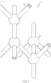
- a three dimensional lattice 10 is formed from a plurality of tubes 20 and a plurality of hubs 30.
- each hub 30 is directly connected to four different tubes 20, and each tube 20 is directly connected to two different hubs 30.
- a "tube,” as used herein, is an enclosed passageway between two distinct locations, and a "hub,” as used herein, is an enclosed area in direct fluid communication with a plurality of tubes 20.
- the hub 30 is directly connected to at least three of the plurality of tubes 20, where the hubs 30 and the tubs 20 can be configured in a variety of embodiments.
- the plurality of tubes 20 and plurality of hubs 30 are configured in a repeating pattern to form the lattice 10.
- a "lattice,” as used herein, is a three dimensional arrangement of components within a space that forms a continuous connection between any two components within the lattice, where the components do not fill the entire space.
- the lattice 10 is formed from a repeating pattern, such as a diamond pattern.
- FIG. 2 illustrates five hubs 30 in a diamond shape, where the spheres represent hubs 30 and the lines represent tubes 20, with continuing reference to FIG. 1 .
- each tube 20 directly connected to an individual hub 30 is about 110 degrees (such as from about 100 to about 120 degrees) from every other tube 20 directly connected to that hub 30, but alternate patterns with varying angles may also be used.
- This diamond pattern can be repeated to fill a space and form a lattice 10.
- This diamond pattern is the same pattern formed by carbon atoms and covalent bonds in a diamond.
- the lattice 10 is connected to a vessel wall 12 at a plurality of discrete locations, and the vessel wall 12 may be connected to the lattice 10 at every location where the repeating pattern intersects the vessel wall 12.
- the lattice 11 may be formed from a plurality of tubes 21 and hubs 31 with a repeating pattern other than the diamond pattern described above.
- the repeating pattern may have six tubes 21 intersecting a hub 31, where every tube 21 intersecting the hub 31 is either 90 degrees or 180 degrees from a reference tube 21 that intersects the hub 31, as illustrated best in FIG. 3 .
- Fig. 4 is a cross sectional view sectioned on a plane in front of a plurality of hubs 31. Fluid flowing vertically in the embodiment illustrated in FIG. 4 could flow in essentially a straight line, with some agitation within the hubs 31.
- the lattice 11 may be formed from a variety of shapes such that no recognizable repeating pattern is used.
- the lattice 11 includes a plurality of tubes 21 and a plurality of hubs 31, where the lattice 11 is connected to the vessel wall 9 in a plurality of discrete locations, such as every location where the lattice 11 intersects the vessel wall 9.
- the lattice 11 may be formed from a plurality of rods (not illustrated), where the rods are solid instead of hollow like a tube.
- the rods may be combined in a manner similar to the tubes 21 and hubs 31 described above with the exception that no fluid can flow within the solid rods.
- the connection of the lattice 11 to the vessel wall 9 supports the vessel wall 9 at a plurality of discrete locations, and may tie vessel walls 9 on opposite sides of a vessel together to further increase the stiffness and strength of the vessel wall 9.
- FIG. 5 an intersection of a tube 20 and a vessel wall 12 are illustrated in cross section, where the illustration shows two opposite walls of the tube 20.
- the tube 20 has walls with a tube thickness 22 and the vessel wall 12 has a vessel wall thickness 8.
- the vessel wall thickness 8 may be from about 25 percent less than the tube thickness 22 to about 25 percent greater than the tube thickness 22 in some embodiments. In many typical embodiments without internal lattices, the vessel wall thickness 8 is significantly greater than the tube thickness 22, and may be orders of magnitude thicker.
- the thinner vessel wall thickness 8 described herein is possible because of the support provided by the internal lattice 10.
- the tube thickness 22 and the vessel wall thickness 8 is from about 0.1 millimeters to about 0.6 millimeters.
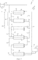
- the hydrogen production system 40 may include a plurality of separate chambers 41, and the number of chambers 41 may vary in different embodiments.
- the hydrogen production system 40 includes a reformer reactor 42, a first superheater heat exchanger 44, a second superheater heat exchanger 46, a water gas shift reactor 48, a reformate cooler heat exchanger 50, and a condenser heat exchanger 52.
- the entire hydrogen production system 40 includes an outer wall referred to herein as an outer shell 54.
- the hydrogen production system 40 also includes a first header 56 and a second header 58, where the first and second headers 56, 58 are connected to the plurality of chambers 41 (reformer reactor 42, first and second superheater heat exchangers 44, 46, water gas shift reactor 48, reformate cooler heat exchanger 50, and condenser heat exchanger 52 .)
- the first and second headers 56, 58 provide conduits to direct fluid flow between the chambers 41, as described more fully below.
- the first and second headers 56, 58 direct fluid flow, so the plurality of chambers 41 are in fluid communication with each other through the first and second headers 56, 58.
- All the chambers 41 within the hydrogen production system 40 are in fluid communication with each other where fluid may flow between the different chambers 41 through the inner flow path and/or the outer flow path of the different chambers 41.
- fluid communication means a fluid is capable of flowing from one chamber 41 to another, where there may or may not be an intermediate chamber 41 through which the fluid flows.
- the reformer reactor 42 includes a plurality of reformer tubes 23 and reformer hubs 33 forming a reformer lattice 13, where the reformer lattice 13 is connected to a reformer reactor wall 47 at a plurality of discrete locations which may be referred to herein as a reformer plurality of discrete locations for specific identification;
- the first superheater heat exchanger 44 includes a plurality of first superheater HE tubes 24 and first superheater HE hubs 34 forming a first superheater HE lattice 14;
- the second superheater heat exchanger 46 includes a plurality of second superheater HE tubes 25 and second superheater HE hubs 35 forming a second superheater lattice 15;
- the water gas shift reactor 48 includes a plurality of shift tubes 26 and shift hubs 36 forming a shift lattice 16, where the shift lattice 16 is connected to the a shift reactor wall 49 at a plurality of discrete locations which may be
- the chambers 41 in the illustrated embodiment include a reformer inner flow path, a reformer outer flow path, first and second superheater HE inner flow paths, first and second superheater HE outer flow paths, a shift inner flow path, a shift outer flow path, a cooler inner flow path, a cooler outer flow path, a condenser inner flow path, and a condenser outer flow path.
- the first and second headers 56, 58 are configured to separately direct fluid for each chamber 41 from the inner and outer flow paths without mixing the two, so separate fluid streams can concurrently pass through each chamber 41 and remain separated within the inner and outer flow paths. (note: flow paths within the first and second headers 56, 58 are not illustrated).
- the lattices 10 include significant surface area from the plurality of tubes 20 and hubs 30, so there is a high rate of heat exchange between the inner and outer flow paths for an individual chamber 41 when the lattice 10 is formed from a material with a high heat transfer rate.
- Fuel 60 is provided from a fuel storage device 62.
- the fuel 60 is a hydrocarbon that may or may not include oxygen atoms, nitrogen atoms, sulfur atoms, or other types of atoms.
- the fuel is a liquid at atmospheric pressure and a temperature of about ambient, such as from about 20 to about 30 °C, which is referred to herein as a "liquid fuel.”
- the fuel 60 may be jet fuel in an exemplary embodiment, but other fuels may be used in alternate embodiments, such as gasoline, diesel fuel, ethanol, fuel oil, kerosene, etc.
- the reformer reactor 42 may be divided into a reformer side 43 and a combustor side 45, where the reformer side 43 is one of the reformer inner flow path and the reformer outer flow path and the combustor side 45 is the other of the reformer inner flow path and the reformer outer flow path.
- Fuel 60 is provided to the reformer side 43 and to the combustor side 45, and the same fuel 60 that is provided to the reformer side 43 may be provided to the combustor side 45 in some embodiments. However, in other embodiments, different fuels 60 may be provided to the reformer side 43 and the combustor side 45.
- a reformer catalyst (not individually illustrated) is present in a reformer side 43 of the reformer reactor 42, and a combustion catalyst (not individually illustrated) is present in a combustor side 45 of the reformer reactor 42.
- the inner and outer flow paths are differentiated from each other in FIG. 7 by the dashed line passing through each chamber 41.
- the reformer catalyst comprises one or more of platinum, rhodium, nickel, or vanadium, but other catalysts are also possible.
- a hydrocarbon fuel 60 and steam are combined and hydrogen gas, carbon monoxide, and perhaps some carbon dioxide are produced.
- Oxygen for the reforming reaction may be provided by air or other sources instead of, or in addition to, steam in alternate embodiments.
- the reforming reaction is typically proceeds at from about 700 to about 1,100 °C and a pressure of from about 3 to about 25 atmospheres, but other reaction conditions are also possible.
- outgas from a fuel cell anode may be combined with the hydrocarbon fuel 60 in the reformer reactor 42 to recover residual hydrogen that passed through the fuel cell (not illustrated).
- the catalytic combustion reaction occurs primarily at the catalyst, which may be deposited on a wall of the reformer tube 23 and/or the reformer hubs 33, so heat transfer from the catalytic combustion reaction to the reforming reaction tends to be high.
- the fluid flow through the reformer side 43 and the combustion side 45 of the reformer reactor 42 may be countercurrent or co-current in different embodiments, as is true for all the chambers 41.
- Fuel 60 is combined with an air supply 64 and introduced to the combustor side 45, where the fuel 60 is catalytically combusted to produce heat.
- Fuel 60 is combined with superheated steam from a superheated steam supply 72 and introduced to reformer side 43 where the fuel 60 is reformed to produce hydrogen gas and carbon monoxide.
- the reforming reaction is endothermic, so heat is added to maintain a desired temperature during the reaction. Heat is produced by the combustion of fuel 60 on the combustor side 45, so heat may be added to the reformer side 43 along the entire length of the reformer reactor 42, which may reduce undesired temperature drop along the length of the reformer side 43.
- a combustion reaction and a reforming reaction separately occur within a single reformer reactor 42, which decreases the size and weight of the hydrogen production system 40 as a whole.
- the two different types of reactions are possible because the reformer reactor 42 includes reformer inner and outer flow paths, with separate and distinct reactions possible in each flow path.
- the combined reformer reactor 42 with the reformer side 43 and the combustor side 45 can be viewed as a plurality of sets of reactors in parallel, so the temperature along the length and/or width remains relatively constant during the reforming reaction.
- the discharge from the combustor side 45 of the reformer reactor 42 is an exhaust 68, and the discharge from the reformer side 43 of the reformer reactor 42 is a reformate 70.
- the reformate 70 is directed to a first superheater heat exchanger 44, where heat from the reformate 70 is transferred to a superheated steam supply 72.
- the superheated steam supply 72 is combined with the fuel 60 for the reformer side 43 of the reformer reactor 42.
- Some of the exhaust 68 may be discharged, but in an exemplary embodiment some or all of the exhaust 68 is directed to a second superheater heat exchanger 45 to transfer heat to the superheated steam supply 72, where the superheated steam supply 72 is heated in each of the first and second superheater heat exchangers 44, 46.
- the exhaust 68 may be discharged after providing heat to the superheated steam supply 72 in some embodiments.
- the reformate 70 may flow to the water gas shift reactor 48 after passing through the first superheater heat exchanger 44.
- a portion of the superheated steam supply 72 such as from the second superheater heat exchanger 46, may be combined with the reformate 70 to pass through a shift reactor side 73 of the water gas shift reactor 48.
- the shift reactor side 73 is one of the shift inner flow path and the shift outer flow path, and a shift heat exchanger side 75 is the other of the shift inner flow path and the shift outer flow path.
- the shift reactor side 73 includes a water gas shift catalyst, which may comprise copper, cuprous oxide, iron oxide, chromium oxide, zinc oxide, aluminum oxide, other transition metal oxides, noble metal oxides, or other materials in various embodiments.
- the water gas shift reaction combines steam and carbon monoxide to produce hydrogen and carbon dioxide, and is typically conducted at from about 200 to about 450 °C and a pressure of from about 1 to about 20 atmospheres.
- the water gas shift reaction is exothermic, and produces a shift reformate 74 that has a higher hydrogen concentration than the reformate 70 entering the shift reactor side 73.
- Heat from the exothermic water gas shift reaction is recovered and pre-heats a water supply 76, where the water supply 76 is eventually heated to become the superheated steam supply 72.
- the water supply 76 may be in a liquid or gaseous state when entering the shift heat exchanger side 75, and the water supply 76 may be in the gaseous state when leaving the shift heat exchanger side 75 in some embodiments.
- the water supply 76 passes through the shift heat exchanger side 75 to recover heat from the water gas shift reaction.
- the shift reformate 74 may be further cooled in a reformate cooler heat exchanger 50 and a condenser heat exchanger 52 before being introduced to a fuel cell 80. This cooling may condense water from the shift reformate 74, which serves to increase the hydrogen concentration in the shift reformate 74.
- the air supply 64 may be pre-heated in the condenser heat exchanger 52, where the shift reformate 74 and the air supply 64 each mutually exclusively pass through one of the condenser inner flow path and the condenser outer flow path of the condenser heat exchanger 52.
- the water supply 76 and the shift reformate 74 may each mutually exclusively pass through one of the cooler inner flow path and the cooler outer flow path of the reformate cooler heat exchanger 50.
- the hydrogen production system 40 is water positive, meaning more water is produced than is used, and the water may be recovered such that there is no need to provide additional water to the hydrogen production system 40 when in use.
- Much of the water may be provided as a by-product from the fuel cell 80, and a significant portion may also be produced in the water gas shift reactor 48.
- the fuel cell 80 may produce heat, and reclaimed water may be used to cool the fuel cell 80 and thereby pre-heat the reclaimed water for use in the hydrogen production system 40. Additional water is produced in the combustor side of the reformate reactor 42 and this water may be collected and re-used as well.
- the water may be primarily provided by the fuel cell 80 and the water gas shift reactor 48 in some embodiments.
- the hydrogen production system 40 may operate without routine and systematic addition of water.
- the hydrogen production system 40 described above is one example of many different possible embodiments.
- chambers 41 that operate at higher temperatures are positioned closer to the center of the hydrogen production system 40, and chambers 41 that operate at lower temperatures are positioned closer to the outer shell 54, where the hydrogen production system 40 as a whole may be cylindrical in some embodiments.
- the chambers 41 may be "nested," one within another, with heat generally flowing from the hottest chamber 41 at or near the center of the hydrogen production system 40 towards the coldest chamber 41 at or near the outer shell 54.
- External ambient temperatures may provide some cooling for an outermost chamber 41 through the outer shell 54 in some embodiments.
- alternative embodiments may include the nesting chambers, with the chamber 41 having the hottest operating temperature at or near the center, and gradually transitioning through successively cooler chambers until reaching an outmost chamber 41 bound by the outer shell 54 that has the coldest operating temperature relative to any of the other chambers 41 in the hydrogen production system 40.
- Possible additional functional elements that may be included in a chamber 41 of the hydrogen production system 40 or as a separate component include a peltier heat exchanger (not illustrated) to better condense water from the shift reformate 74 before entering the fuel cell 80, a sulfur removal unit to remove sulfur from the fuel 60 or from the hydrogen produced from the fuel 60, water removal units; etc.
- the hydrogen production system 40 may include one or more bi-metallic actuators (not illustrated) that open or close based on temperature. The bi-metallic actuators may be positioned to control flow such that operating temperatures are maintained within desired ranges, and flows are properly regulated during start-up and shut-down processes.
- the lattice 10 is connected to vessel walls 12 at a plurality of discrete locations, as described above, but the production of a hydrogen production system 40 having chambers 41 with internal lattices 10 can present a machining challenge.
- additive manufacturing may be used to produce the hydrogen production system 40, and the additive manufacturing may also be used to produce the first and second headers 56, 58.
- Additive manufacturing sometimes referred to as 3-D printing, involves a process where successive layers of an object are formed.
- the feed material may be a powdered metal or a metal feed supply, such as a wire. In an exemplary embodiment with a powdered feed material, powdered metal is applied to a base and melted in desired locations.
- the powdered material may be melted with an energy beam, such as a laser, electron beam, or other energy beam.
- the melted powder is solidified to form a layer of the desired product.
- More powdered metal is provided and melted in desired locations to form the next layer, and the process proceeds.
- wire feed process wire is melted and deposited in desired locations on a base or on previous layers to gradually build up a desired shape.
- Additive manufacturing allows for the production of complex shapes, including the lattice 10 positioned within the hydrogen production system 40, because the item is gradually built up in layers. This allows for complex internal structures that are not readily accessible for more traditional machining.
- the catalysts may be deposited within the hydrogen production system 40 prior to adding the first and second headers 56, 58.
- the hydrogen production system 40 may include a single body that has all the chambers 41, and separate first and second headers 56, 58 that are connected to the single body. However, in alternate embodiments the hydrogen production system 40 may include a body with two or more parts, where the two or more parts may be nested as described above or may be separate parts.
- the various catalysts may be deposited within the desired chambers 41 by masking off undesired chambers 41 and flowing a wash coat with the catalyst through the desired location. The catalyst remains in a residual layer, and the catalyst may be fixed by an anneal or other heat treatment. The catalyst deposition technique may be repeated to obtain the desired catalyst loading. Different catalysts may be sequentially deposited, or they may be simultaneously deposited if the masking, wash coating, and heat treating processes allow.
- the first and second headers 56, 58 may be attached to a main body of the hydrogen production system 40 by sonic welding, with the use of a gasket and clamps, or with other techniques.
- the bi-metallic actuators (not illustrated), if present, may be mechanically fastened to the first and/or second headers 56, 58 prior to assembly. In an alternate embodiment, the bi-metallic actuators may be mechanically fastened to the body at the entrance or exit of a chamber 41 prior to assembly of the body and the first and second headers 56, 58.
- Alternative techniques may also be used to include the bi-metallic actuators in the hydrogen production system 40.
- the bi-metallic actuators may include two different metals such that they actuators move with changing temperatures, where the movement serves to either open or close a passageway.
- the hydrogen production system 40 may also include check valves and other flow control devices in various embodiments.
- the additive manufacturing process enables the production a hydrogen production system 40 that is sized and shaped for specific locations.
- an aircraft may have a "C" shaped space with sufficient volume to accommodate a hydrogen production system with a desired capacity, so a "C” shaped hydrogen production system 40 may be produced to fit the available space.
- the outer shell 54 includes a concave side and a convex side for the "C" shape, and the chambers 41 are arranged within the "C" shape. Alternate embodiments include a cubic shape, a "plus sign" shape, and many other desired shapes.
- the lattice structure connected to vessel walls 12 at a plurality of discrete locations, as described above, enables the use of thinner containment walls for the various chambers 41.
- the thinner containment walls can reduce the weight and volume of the hydrogen production system 40, and the reduced weight and volume increases design options for the use of hydrogen production systems 40 and the associated fuel cells 80.
Landscapes
- Chemical & Material Sciences (AREA)
- Chemical Kinetics & Catalysis (AREA)
- Organic Chemistry (AREA)
- Engineering & Computer Science (AREA)
- Health & Medical Sciences (AREA)
- Inorganic Chemistry (AREA)
- Combustion & Propulsion (AREA)
- General Health & Medical Sciences (AREA)
- Sustainable Development (AREA)
- General Chemical & Material Sciences (AREA)
- Electrochemistry (AREA)
- Sustainable Energy (AREA)
- Manufacturing & Machinery (AREA)
- Life Sciences & Earth Sciences (AREA)
- Hydrogen, Water And Hydrids (AREA)
Claims (13)
- Système de production d'hydrogène (40) comprenant :un réacteur de reformage (2) comportant une paroi de réacteur de reformage (47) ;une pluralité de tubes de reformage (23) qui sont interconnectés de façon à définir un treillis de reformage (13) avec une voie d'écoulement interne de reformage et une voie d'écoulement externe de reformage, le treillis de reformage (13) étant un treillis tridimensionnel, la pluralité de tubes de reformage (23) se trouvant à l'intérieur du réacteur de reformage (42), la pluralité de tubes de reformage (23) étant rattachés à la paroi du réacteur de reformage (47) à une pluralité d'emplacements discrets de manière à ce que le treillis de reformage (13) supporte la paroi du réacteur de reformage (47), le treillis de reformage (13) définissant un côté chambre de combustion (45) qui est soit la voie d'écoulement interne de reformage, soit la voie d'écoulement externe de reformage, et le treillis de reformage (13) définissant un côté reformeur (43) qui est l'autre que la voie d'écoulement interne de reformage ou que la voie d'écoulement externe de reformage ; etun catalyseur de reformage positionné à l'intérieur du côté reformeur (43).
- Système de production d'hydrogène (40) selon la revendication 1, comprenant en outre :
une pluralité de noeuds de reformage (33) positionnés à l'intérieur du réacteur de reformage (42), chacun de cette pluralité de noeuds de reformage (33) étant rattaché à au moins trois de la pluralité de tubes de reformage (23). - Système de production d'hydrogène (40) selon la revendication 2, dans lequel chacun de la pluralité de tubes de reformage (23) rattaché directement à un de la pluralité de noeuds de reformage (33) étant à environ 110 degrés de chaque autre de la pluralité de tubes de reformage (23) directement rattaché audit un de la pluralité de noeuds de reformage (33).
- Système de production d'hydrogène (40) selon la revendication 2, dans lequel la pluralité de tubes de reformage (23) et la pluralité de noeuds de reformage (33) forment un treillis (10) qui comporte une forme qui se répète et qui remplit à peu près le réacteur de reformage (42).
- Système de production d'hydrogène (40) selon la revendication 1, comprenant en outre :
une alimentation en air (64) configurée de façon à alimenter de l'air au côté chambre de combustion (45) du réacteur de reformage (42). - Système de production d'hydrogène (40) selon la revendication 1, dans lequel :la pluralité de tubes de reformage (23) comporte une épaisseur de tubes (22) ; etla paroi du réacteur de reformage (47) comporte une épaisseur de paroi de récipient (8) qui est entre environ 25 pourcent plus mince que l'épaisseur des tubes (22) et environ 25 pourcent plus épaisse que l'épaisseur des tubes (22)c
- Système de production d'hydrogène (40) selon la revendication 1, comprenant en outre :un réacteur de conversion du gaz à l'eau (48) en communication fluidique avec le réacteur de reformage (42) ;un premier échangeur de chaleur surchauffeur (44) en communication fluidique avec le réacteur de conversion du gaz à l'eau (48), ce premier échangeur de chaleur surchauffeur (44) étant en communication fluidique avec le réacteur de reformage (42) ; etune coquille extérieure (54), le réacteur de reformage (42), le réacteur de conversion du gaz à l'eau (48), et le premier échangeur de chaleur surchauffeur (44) étant à l'intérieur de cette coquille extérieure (54).
- Système de production d'hydrogène (40) selon la revendication 7, comprenant en outre :un premier collecteur (56) rattaché à la coquille extérieure (54), au réacteur de reformage (42), au réacteur de conversion du gaz à l'eau (48), et au premier échangeur de chaleur surchauffeur (44) ; etun deuxième collecteur (56) rattaché à la coquille extérieure (54), au réacteur de reformage (42), au réacteur de conversion du gaz à l'eau (48), et au premier échangeur de chaleur surchauffeur (44) ; etce premier collecteur (56) et ce deuxième collecteur (58) fournissant une communication fluidique entre le réacteur de reformage (42), le réacteur de conversion du gaz à l'eau (48), et le premier échangeur de chaleur surchauffeur (44).
- Système de production d'hydrogène (40) selon la revendication 8, comprenant en outre :un échangeur de chaleur refroidisseur de reformat (50) ; etun échangeur de chaleur condenseur (52), l'échangeur de chaleur refroidisseur de reformat (50) et l'échangeur de chaleur condenseur (52) étant positionnés à l'intérieur de la coquille extérieure (54) .
- Système de production d'hydrogène (40) selon la revendication 7, dans lequel la coquille extérieure (54) a un côté concave et un côté convexe de telle sorte que la coquille extérieure (54) a une forme en « C ».
- Système de production d'hydrogène (40) selon la revendication 1, comprenant en outre un catalyseur de combustion à l'intérieur du côté chambre de combustion (45) .
- Système de production d'hydrogène (40) selon la revendication 1, dans lequel le treillis de reformage (13) est rattaché à la paroi du réacteur de reformage (47) à chaque emplacement où le treillis entrecoupe la paroi du réacteur de reformage (47).
- Système de production d'hydrogène (40) selon la revendication 1, ce système de production d'hydrogène (40) étant configuré de façon à fournir une vapeur surchauffée au côté reformeur (43).
Applications Claiming Priority (1)
| Application Number | Priority Date | Filing Date | Title |
|---|---|---|---|
| US15/488,736 US10128518B2 (en) | 2017-04-17 | 2017-04-17 | Hydrogen production system and methods of producing the same |
Publications (2)
| Publication Number | Publication Date |
|---|---|
| EP3392196A1 EP3392196A1 (fr) | 2018-10-24 |
| EP3392196B1 true EP3392196B1 (fr) | 2019-06-19 |
Family
ID=61972403
Family Applications (1)
| Application Number | Title | Priority Date | Filing Date |
|---|---|---|---|
| EP18167130.6A Active EP3392196B1 (fr) | 2017-04-17 | 2018-04-12 | Système de production d'hydrogène |
Country Status (2)
| Country | Link |
|---|---|
| US (1) | US10128518B2 (fr) |
| EP (1) | EP3392196B1 (fr) |
Families Citing this family (2)
| Publication number | Priority date | Publication date | Assignee | Title |
|---|---|---|---|---|
| US10369540B2 (en) * | 2017-04-17 | 2019-08-06 | Honeywell International Inc. | Cell structures for use in heat exchangers, and methods of producing the same |
| US11602723B2 (en) * | 2018-01-05 | 2023-03-14 | 3D-Cat B.V. | Modular additive manufactured reactor system |
Family Cites Families (29)
| Publication number | Priority date | Publication date | Assignee | Title |
|---|---|---|---|---|
| US3172739A (en) | 1962-02-06 | 1965-03-09 | Koniewiez | |
| US3453087A (en) | 1964-06-25 | 1969-07-01 | Girdler Corp | Modular reformer furnace |
| US3667429A (en) | 1971-01-25 | 1972-06-06 | Lummus Co | Fired heater |
| US3980440A (en) * | 1975-08-06 | 1976-09-14 | General Atomic Company | Catalyst tube assembly for steam-hydrocarbon reformer |
| US4547356A (en) | 1980-08-05 | 1985-10-15 | Unique Energy Systems, Inc. | Method of generating hydrogen and using the generated hydrogen |
| US4820314A (en) | 1987-02-11 | 1989-04-11 | International Fuel Cells Corporation | Fuel cell power plant reformer |
| JP3625770B2 (ja) | 1999-04-20 | 2005-03-02 | 東京瓦斯株式会社 | 単管円筒式改質器およびその運転方法 |
| US6641625B1 (en) | 1999-05-03 | 2003-11-04 | Nuvera Fuel Cells, Inc. | Integrated hydrocarbon reforming system and controls |
| WO2002025762A1 (fr) | 2000-09-20 | 2002-03-28 | Kabushiki Kaisha Toshiba | Dispositif de reformage de combustible destine a des piles a combustible a haut polymere solide |
| CA2357960C (fr) | 2000-10-10 | 2007-01-30 | Tokyo Gas Co., Ltd. | Reformeur a cylindres et a conduite unique |
| JP4479117B2 (ja) | 2001-03-15 | 2010-06-09 | アイシン精機株式会社 | 燃料改質装置 |
| US6713040B2 (en) | 2001-03-23 | 2004-03-30 | Argonne National Laboratory | Method for generating hydrogen for fuel cells |
| JP3706611B2 (ja) | 2002-11-21 | 2005-10-12 | 三洋電機株式会社 | 燃料電池用水素発生装置 |
| US20070104983A1 (en) | 2003-12-03 | 2007-05-10 | Hidenobu Wakita | Fuel cell system |
| KR100570697B1 (ko) | 2004-09-24 | 2006-04-12 | 삼성에스디아이 주식회사 | 연료 전지 시스템 및 이에 사용되는 개질기 |
| KR101127688B1 (ko) | 2004-12-07 | 2012-03-23 | 에스케이이노베이션 주식회사 | 원통형 소형 개질 장치 |
| KR101240704B1 (ko) | 2006-01-17 | 2013-03-07 | 삼성에스디아이 주식회사 | 이동가능한 열원을 갖는 연료개질 시스템 및 이를 구비한연료전지 시스템 |
| KR101328983B1 (ko) | 2006-10-13 | 2013-11-13 | 삼성에스디아이 주식회사 | 수소생성장치 및 그 구동 방법 |
| JP4149510B2 (ja) | 2006-10-16 | 2008-09-10 | 松下電器産業株式会社 | 水素生成装置及びそれを備える燃料電池システム |
| JP5334034B2 (ja) | 2007-04-25 | 2013-11-06 | アイシン精機株式会社 | 改質装置および燃料電池システム |
| US20090042071A1 (en) * | 2007-08-07 | 2009-02-12 | Fischer Bernhard A | Multi-tube fuel reformer with augmented heat transfer |
| US8178062B2 (en) | 2007-09-27 | 2012-05-15 | Sanyo Electric Co., Ltd. | Reforming apparatus for fuel cell |
| US8702823B2 (en) | 2009-01-19 | 2014-04-22 | Panasonic Corporation | Hydrogen generation apparatus, fuel cell system and method of shutting down hydrogen generation apparatus |
| EP2492998B1 (fr) | 2009-10-19 | 2015-04-01 | JX Nippon Oil & Energy Corporation | Système de pile à combustible |
| KR20120047545A (ko) | 2010-11-04 | 2012-05-14 | 삼성에스디아이 주식회사 | 연료 개질 장치 |
| DE102011106654A1 (de) | 2011-04-21 | 2012-10-25 | Airbus Operations Gmbh | Verfahren zum Herstellen eines Festoxid-Brennstoffzellen-Elements durch schichtweisen Aufbau und ein Festoxid-Brennstoffzellen-Element |
| US9440216B2 (en) | 2012-03-15 | 2016-09-13 | Geosepaa Llc | Minimal surface area mass and heat transfer packing |
| JP5895169B2 (ja) | 2012-12-17 | 2016-03-30 | パナソニックIpマネジメント株式会社 | 水素生成装置 |
| US10995996B2 (en) | 2014-10-07 | 2021-05-04 | Unison Industries, Llc | Multi-branch furcating flow heat exchanger |
-
2017
- 2017-04-17 US US15/488,736 patent/US10128518B2/en active Active
-
2018
- 2018-04-12 EP EP18167130.6A patent/EP3392196B1/fr active Active
Non-Patent Citations (1)
| Title |
|---|
| None * |
Also Published As
| Publication number | Publication date |
|---|---|
| US20180301725A1 (en) | 2018-10-18 |
| EP3392196A1 (fr) | 2018-10-24 |
| US10128518B2 (en) | 2018-11-13 |
Similar Documents
| Publication | Publication Date | Title |
|---|---|---|
| US12098079B2 (en) | Chemical reactor with integrated heat exchanger, heater, and high conductance catalyst holder | |
| US7883672B2 (en) | Small cylindrical reformer | |
| US10773229B2 (en) | Steam reformers, modules, and methods of use | |
| CA3098785C (fr) | Reformage à la vapeur chauffé par chauffage par résistance | |
| JP7768910B2 (ja) | 膜改質器を用いた水素の生産 | |
| US10369540B2 (en) | Cell structures for use in heat exchangers, and methods of producing the same | |
| US20080194712A1 (en) | Process an apparatus for steam-methane reforming | |
| CN110267912B (zh) | 用于合成气生产的可扩展换热器转化炉 | |
| JP2004537487A (ja) | イオン輸送膜装置及び方法 | |
| JP2007528340A (ja) | 分散型水素製造のための高度に一体化した燃料プロセッサ | |
| KR20210059656A (ko) | 탄소배출이 없는 수소 생산 반응기 | |
| US10128518B2 (en) | Hydrogen production system and methods of producing the same | |
| JP2012521960A (ja) | 受動熱流束制御要素を伴う蒸気改質器 | |
| TWI885872B (zh) | 使用復熱式熱交換反應器之氨裂解程序 | |
| JP7854043B2 (ja) | リアクター及びアンモニアを分解する装置と方法 | |
| JP4295061B2 (ja) | 蒸発器 | |
| KR20250082012A (ko) | 암모니아 분해 반응을 이용한 수소 생산 반응기 | |
| JP2026515519A (ja) | 復熱式熱交換反応器を用いるアンモニア分解プロセス |
Legal Events
| Date | Code | Title | Description |
|---|---|---|---|
| PUAI | Public reference made under article 153(3) epc to a published international application that has entered the european phase |
Free format text: ORIGINAL CODE: 0009012 |
|
| STAA | Information on the status of an ep patent application or granted ep patent |
Free format text: STATUS: REQUEST FOR EXAMINATION WAS MADE |
|
| 17P | Request for examination filed |
Effective date: 20180412 |
|
| AK | Designated contracting states |
Kind code of ref document: A1 Designated state(s): AL AT BE BG CH CY CZ DE DK EE ES FI FR GB GR HR HU IE IS IT LI LT LU LV MC MK MT NL NO PL PT RO RS SE SI SK SM TR |
|
| AX | Request for extension of the european patent |
Extension state: BA ME |
|
| GRAP | Despatch of communication of intention to grant a patent |
Free format text: ORIGINAL CODE: EPIDOSNIGR1 |
|
| STAA | Information on the status of an ep patent application or granted ep patent |
Free format text: STATUS: GRANT OF PATENT IS INTENDED |
|
| INTG | Intention to grant announced |
Effective date: 20190107 |
|
| GRAS | Grant fee paid |
Free format text: ORIGINAL CODE: EPIDOSNIGR3 |
|
| GRAA | (expected) grant |
Free format text: ORIGINAL CODE: 0009210 |
|
| STAA | Information on the status of an ep patent application or granted ep patent |
Free format text: STATUS: THE PATENT HAS BEEN GRANTED |
|
| AK | Designated contracting states |
Kind code of ref document: B1 Designated state(s): AL AT BE BG CH CY CZ DE DK EE ES FI FR GB GR HR HU IE IS IT LI LT LU LV MC MK MT NL NO PL PT RO RS SE SI SK SM TR |
|
| REG | Reference to a national code |
Ref country code: GB Ref legal event code: FG4D |
|
| REG | Reference to a national code |
Ref country code: CH Ref legal event code: EP |
|
| REG | Reference to a national code |
Ref country code: IE Ref legal event code: FG4D |
|
| REG | Reference to a national code |
Ref country code: DE Ref legal event code: R096 Ref document number: 602018000160 Country of ref document: DE |
|
| REG | Reference to a national code |
Ref country code: AT Ref legal event code: REF Ref document number: 1145268 Country of ref document: AT Kind code of ref document: T Effective date: 20190715 |
|
| REG | Reference to a national code |
Ref country code: NL Ref legal event code: MP Effective date: 20190619 |
|
| PG25 | Lapsed in a contracting state [announced via postgrant information from national office to epo] |
Ref country code: AL Free format text: LAPSE BECAUSE OF FAILURE TO SUBMIT A TRANSLATION OF THE DESCRIPTION OR TO PAY THE FEE WITHIN THE PRESCRIBED TIME-LIMIT Effective date: 20190619 Ref country code: LT Free format text: LAPSE BECAUSE OF FAILURE TO SUBMIT A TRANSLATION OF THE DESCRIPTION OR TO PAY THE FEE WITHIN THE PRESCRIBED TIME-LIMIT Effective date: 20190619 Ref country code: SE Free format text: LAPSE BECAUSE OF FAILURE TO SUBMIT A TRANSLATION OF THE DESCRIPTION OR TO PAY THE FEE WITHIN THE PRESCRIBED TIME-LIMIT Effective date: 20190619 Ref country code: HR Free format text: LAPSE BECAUSE OF FAILURE TO SUBMIT A TRANSLATION OF THE DESCRIPTION OR TO PAY THE FEE WITHIN THE PRESCRIBED TIME-LIMIT Effective date: 20190619 Ref country code: FI Free format text: LAPSE BECAUSE OF FAILURE TO SUBMIT A TRANSLATION OF THE DESCRIPTION OR TO PAY THE FEE WITHIN THE PRESCRIBED TIME-LIMIT Effective date: 20190619 Ref country code: NO Free format text: LAPSE BECAUSE OF FAILURE TO SUBMIT A TRANSLATION OF THE DESCRIPTION OR TO PAY THE FEE WITHIN THE PRESCRIBED TIME-LIMIT Effective date: 20190919 |
|
| REG | Reference to a national code |
Ref country code: LT Ref legal event code: MG4D |
|
| PG25 | Lapsed in a contracting state [announced via postgrant information from national office to epo] |
Ref country code: BG Free format text: LAPSE BECAUSE OF FAILURE TO SUBMIT A TRANSLATION OF THE DESCRIPTION OR TO PAY THE FEE WITHIN THE PRESCRIBED TIME-LIMIT Effective date: 20190919 Ref country code: LV Free format text: LAPSE BECAUSE OF FAILURE TO SUBMIT A TRANSLATION OF THE DESCRIPTION OR TO PAY THE FEE WITHIN THE PRESCRIBED TIME-LIMIT Effective date: 20190619 Ref country code: GR Free format text: LAPSE BECAUSE OF FAILURE TO SUBMIT A TRANSLATION OF THE DESCRIPTION OR TO PAY THE FEE WITHIN THE PRESCRIBED TIME-LIMIT Effective date: 20190920 Ref country code: RS Free format text: LAPSE BECAUSE OF FAILURE TO SUBMIT A TRANSLATION OF THE DESCRIPTION OR TO PAY THE FEE WITHIN THE PRESCRIBED TIME-LIMIT Effective date: 20190619 |
|
| REG | Reference to a national code |
Ref country code: AT Ref legal event code: MK05 Ref document number: 1145268 Country of ref document: AT Kind code of ref document: T Effective date: 20190619 |
|
| PG25 | Lapsed in a contracting state [announced via postgrant information from national office to epo] |
Ref country code: EE Free format text: LAPSE BECAUSE OF FAILURE TO SUBMIT A TRANSLATION OF THE DESCRIPTION OR TO PAY THE FEE WITHIN THE PRESCRIBED TIME-LIMIT Effective date: 20190619 Ref country code: AT Free format text: LAPSE BECAUSE OF FAILURE TO SUBMIT A TRANSLATION OF THE DESCRIPTION OR TO PAY THE FEE WITHIN THE PRESCRIBED TIME-LIMIT Effective date: 20190619 Ref country code: PT Free format text: LAPSE BECAUSE OF FAILURE TO SUBMIT A TRANSLATION OF THE DESCRIPTION OR TO PAY THE FEE WITHIN THE PRESCRIBED TIME-LIMIT Effective date: 20191021 Ref country code: RO Free format text: LAPSE BECAUSE OF FAILURE TO SUBMIT A TRANSLATION OF THE DESCRIPTION OR TO PAY THE FEE WITHIN THE PRESCRIBED TIME-LIMIT Effective date: 20190619 Ref country code: NL Free format text: LAPSE BECAUSE OF FAILURE TO SUBMIT A TRANSLATION OF THE DESCRIPTION OR TO PAY THE FEE WITHIN THE PRESCRIBED TIME-LIMIT Effective date: 20190619 Ref country code: CZ Free format text: LAPSE BECAUSE OF FAILURE TO SUBMIT A TRANSLATION OF THE DESCRIPTION OR TO PAY THE FEE WITHIN THE PRESCRIBED TIME-LIMIT Effective date: 20190619 Ref country code: SK Free format text: LAPSE BECAUSE OF FAILURE TO SUBMIT A TRANSLATION OF THE DESCRIPTION OR TO PAY THE FEE WITHIN THE PRESCRIBED TIME-LIMIT Effective date: 20190619 |
|
| PG25 | Lapsed in a contracting state [announced via postgrant information from national office to epo] |
Ref country code: IS Free format text: LAPSE BECAUSE OF FAILURE TO SUBMIT A TRANSLATION OF THE DESCRIPTION OR TO PAY THE FEE WITHIN THE PRESCRIBED TIME-LIMIT Effective date: 20191019 Ref country code: ES Free format text: LAPSE BECAUSE OF FAILURE TO SUBMIT A TRANSLATION OF THE DESCRIPTION OR TO PAY THE FEE WITHIN THE PRESCRIBED TIME-LIMIT Effective date: 20190619 Ref country code: IT Free format text: LAPSE BECAUSE OF FAILURE TO SUBMIT A TRANSLATION OF THE DESCRIPTION OR TO PAY THE FEE WITHIN THE PRESCRIBED TIME-LIMIT Effective date: 20190619 Ref country code: SM Free format text: LAPSE BECAUSE OF FAILURE TO SUBMIT A TRANSLATION OF THE DESCRIPTION OR TO PAY THE FEE WITHIN THE PRESCRIBED TIME-LIMIT Effective date: 20190619 |
|
| PG25 | Lapsed in a contracting state [announced via postgrant information from national office to epo] |
Ref country code: TR Free format text: LAPSE BECAUSE OF FAILURE TO SUBMIT A TRANSLATION OF THE DESCRIPTION OR TO PAY THE FEE WITHIN THE PRESCRIBED TIME-LIMIT Effective date: 20190619 |
|
| PG25 | Lapsed in a contracting state [announced via postgrant information from national office to epo] |
Ref country code: DK Free format text: LAPSE BECAUSE OF FAILURE TO SUBMIT A TRANSLATION OF THE DESCRIPTION OR TO PAY THE FEE WITHIN THE PRESCRIBED TIME-LIMIT Effective date: 20190619 Ref country code: PL Free format text: LAPSE BECAUSE OF FAILURE TO SUBMIT A TRANSLATION OF THE DESCRIPTION OR TO PAY THE FEE WITHIN THE PRESCRIBED TIME-LIMIT Effective date: 20190619 |
|
| PG25 | Lapsed in a contracting state [announced via postgrant information from national office to epo] |
Ref country code: IS Free format text: LAPSE BECAUSE OF FAILURE TO SUBMIT A TRANSLATION OF THE DESCRIPTION OR TO PAY THE FEE WITHIN THE PRESCRIBED TIME-LIMIT Effective date: 20200224 |
|
| REG | Reference to a national code |
Ref country code: DE Ref legal event code: R097 Ref document number: 602018000160 Country of ref document: DE |
|
| PLBE | No opposition filed within time limit |
Free format text: ORIGINAL CODE: 0009261 |
|
| STAA | Information on the status of an ep patent application or granted ep patent |
Free format text: STATUS: NO OPPOSITION FILED WITHIN TIME LIMIT |
|
| PG2D | Information on lapse in contracting state deleted |
Ref country code: IS |
|
| 26N | No opposition filed |
Effective date: 20200603 |
|
| PG25 | Lapsed in a contracting state [announced via postgrant information from national office to epo] |
Ref country code: MC Free format text: LAPSE BECAUSE OF FAILURE TO SUBMIT A TRANSLATION OF THE DESCRIPTION OR TO PAY THE FEE WITHIN THE PRESCRIBED TIME-LIMIT Effective date: 20190619 |
|
| PG25 | Lapsed in a contracting state [announced via postgrant information from national office to epo] |
Ref country code: FR Free format text: LAPSE BECAUSE OF NON-PAYMENT OF DUE FEES Effective date: 20200430 Ref country code: LU Free format text: LAPSE BECAUSE OF NON-PAYMENT OF DUE FEES Effective date: 20200412 |
|
| REG | Reference to a national code |
Ref country code: BE Ref legal event code: MM Effective date: 20200430 |
|
| PG25 | Lapsed in a contracting state [announced via postgrant information from national office to epo] |
Ref country code: BE Free format text: LAPSE BECAUSE OF NON-PAYMENT OF DUE FEES Effective date: 20200430 |
|
| PG25 | Lapsed in a contracting state [announced via postgrant information from national office to epo] |
Ref country code: IE Free format text: LAPSE BECAUSE OF NON-PAYMENT OF DUE FEES Effective date: 20200412 |
|
| PG25 | Lapsed in a contracting state [announced via postgrant information from national office to epo] |
Ref country code: CH Free format text: LAPSE BECAUSE OF NON-PAYMENT OF DUE FEES Effective date: 20210430 Ref country code: LI Free format text: LAPSE BECAUSE OF NON-PAYMENT OF DUE FEES Effective date: 20210430 |
|
| PG25 | Lapsed in a contracting state [announced via postgrant information from national office to epo] |
Ref country code: MT Free format text: LAPSE BECAUSE OF FAILURE TO SUBMIT A TRANSLATION OF THE DESCRIPTION OR TO PAY THE FEE WITHIN THE PRESCRIBED TIME-LIMIT Effective date: 20190619 Ref country code: CY Free format text: LAPSE BECAUSE OF FAILURE TO SUBMIT A TRANSLATION OF THE DESCRIPTION OR TO PAY THE FEE WITHIN THE PRESCRIBED TIME-LIMIT Effective date: 20190619 |
|
| PG25 | Lapsed in a contracting state [announced via postgrant information from national office to epo] |
Ref country code: MK Free format text: LAPSE BECAUSE OF FAILURE TO SUBMIT A TRANSLATION OF THE DESCRIPTION OR TO PAY THE FEE WITHIN THE PRESCRIBED TIME-LIMIT Effective date: 20190619 |
|
| GBPC | Gb: european patent ceased through non-payment of renewal fee |
Effective date: 20220412 |
|
| PG25 | Lapsed in a contracting state [announced via postgrant information from national office to epo] |
Ref country code: GB Free format text: LAPSE BECAUSE OF NON-PAYMENT OF DUE FEES Effective date: 20220412 |
|
| P01 | Opt-out of the competence of the unified patent court (upc) registered |
Effective date: 20230525 |
|
| PG25 | Lapsed in a contracting state [announced via postgrant information from national office to epo] |
Ref country code: SI Free format text: LAPSE BECAUSE OF FAILURE TO SUBMIT A TRANSLATION OF THE DESCRIPTION OR TO PAY THE FEE WITHIN THE PRESCRIBED TIME-LIMIT Effective date: 20190619 |
|
| PGFP | Annual fee paid to national office [announced via postgrant information from national office to epo] |
Ref country code: DE Payment date: 20250428 Year of fee payment: 8 |