EP3392471B1 - Lagergehäuse und ein abgasturbolader mit einem solchen gehäuse - Google Patents
Lagergehäuse und ein abgasturbolader mit einem solchen gehäuse Download PDFInfo
- Publication number
- EP3392471B1 EP3392471B1 EP18154911.4A EP18154911A EP3392471B1 EP 3392471 B1 EP3392471 B1 EP 3392471B1 EP 18154911 A EP18154911 A EP 18154911A EP 3392471 B1 EP3392471 B1 EP 3392471B1
- Authority
- EP
- European Patent Office
- Prior art keywords
- bearing housing
- groove
- central axis
- recess
- bearing
- Prior art date
- Legal status (The legal status is an assumption and is not a legal conclusion. Google has not performed a legal analysis and makes no representation as to the accuracy of the status listed.)
- Not-in-force
Links
Images



Classifications
-
- F—MECHANICAL ENGINEERING; LIGHTING; HEATING; WEAPONS; BLASTING
- F02—COMBUSTION ENGINES; HOT-GAS OR COMBUSTION-PRODUCT ENGINE PLANTS
- F02C—GAS-TURBINE PLANTS; AIR INTAKES FOR JET-PROPULSION PLANTS; CONTROLLING FUEL SUPPLY IN AIR-BREATHING JET-PROPULSION PLANTS
- F02C7/00—Features, components parts, details or accessories, not provided for in, or of interest apart form groups F02C1/00 - F02C6/00; Air intakes for jet-propulsion plants
- F02C7/06—Arrangements of bearings; Lubricating
-
- F—MECHANICAL ENGINEERING; LIGHTING; HEATING; WEAPONS; BLASTING
- F01—MACHINES OR ENGINES IN GENERAL; ENGINE PLANTS IN GENERAL; STEAM ENGINES
- F01D—NON-POSITIVE DISPLACEMENT MACHINES OR ENGINES, e.g. STEAM TURBINES
- F01D25/00—Component parts, details, or accessories, not provided for in, or of interest apart from, other groups
- F01D25/16—Arrangement of bearings; Supporting or mounting bearings in casings
- F01D25/166—Sliding contact bearing
-
- F—MECHANICAL ENGINEERING; LIGHTING; HEATING; WEAPONS; BLASTING
- F01—MACHINES OR ENGINES IN GENERAL; ENGINE PLANTS IN GENERAL; STEAM ENGINES
- F01D—NON-POSITIVE DISPLACEMENT MACHINES OR ENGINES, e.g. STEAM TURBINES
- F01D25/00—Component parts, details, or accessories, not provided for in, or of interest apart from, other groups
- F01D25/16—Arrangement of bearings; Supporting or mounting bearings in casings
-
- F—MECHANICAL ENGINEERING; LIGHTING; HEATING; WEAPONS; BLASTING
- F01—MACHINES OR ENGINES IN GENERAL; ENGINE PLANTS IN GENERAL; STEAM ENGINES
- F01D—NON-POSITIVE DISPLACEMENT MACHINES OR ENGINES, e.g. STEAM TURBINES
- F01D25/00—Component parts, details, or accessories, not provided for in, or of interest apart from, other groups
- F01D25/16—Arrangement of bearings; Supporting or mounting bearings in casings
- F01D25/166—Sliding contact bearing
- F01D25/168—Sliding contact bearing for axial load mainly
-
- F—MECHANICAL ENGINEERING; LIGHTING; HEATING; WEAPONS; BLASTING
- F01—MACHINES OR ENGINES IN GENERAL; ENGINE PLANTS IN GENERAL; STEAM ENGINES
- F01D—NON-POSITIVE DISPLACEMENT MACHINES OR ENGINES, e.g. STEAM TURBINES
- F01D25/00—Component parts, details, or accessories, not provided for in, or of interest apart from, other groups
- F01D25/18—Lubricating arrangements
- F01D25/183—Sealing means
- F01D25/186—Sealing means for sliding contact bearing
-
- F—MECHANICAL ENGINEERING; LIGHTING; HEATING; WEAPONS; BLASTING
- F16—ENGINEERING ELEMENTS AND UNITS; GENERAL MEASURES FOR PRODUCING AND MAINTAINING EFFECTIVE FUNCTIONING OF MACHINES OR INSTALLATIONS; THERMAL INSULATION IN GENERAL
- F16C—SHAFTS; FLEXIBLE SHAFTS; ELEMENTS OR CRANKSHAFT MECHANISMS; ROTARY BODIES OTHER THAN GEARING ELEMENTS; BEARINGS
- F16C33/00—Parts of bearings; Special methods for making bearings or parts thereof
- F16C33/72—Sealings
- F16C33/74—Sealings of sliding-contact bearings
- F16C33/741—Sealings of sliding-contact bearings by means of a fluid
- F16C33/743—Sealings of sliding-contact bearings by means of a fluid retained in the sealing gap
-
- F—MECHANICAL ENGINEERING; LIGHTING; HEATING; WEAPONS; BLASTING
- F16—ENGINEERING ELEMENTS AND UNITS; GENERAL MEASURES FOR PRODUCING AND MAINTAINING EFFECTIVE FUNCTIONING OF MACHINES OR INSTALLATIONS; THERMAL INSULATION IN GENERAL
- F16C—SHAFTS; FLEXIBLE SHAFTS; ELEMENTS OR CRANKSHAFT MECHANISMS; ROTARY BODIES OTHER THAN GEARING ELEMENTS; BEARINGS
- F16C35/00—Rigid support of bearing units; Housings, e.g. caps, covers
- F16C35/04—Rigid support of bearing units; Housings, e.g. caps, covers in the case of ball or roller bearings
- F16C35/042—Housings for rolling element bearings for rotary movement
-
- F—MECHANICAL ENGINEERING; LIGHTING; HEATING; WEAPONS; BLASTING
- F01—MACHINES OR ENGINES IN GENERAL; ENGINE PLANTS IN GENERAL; STEAM ENGINES
- F01D—NON-POSITIVE DISPLACEMENT MACHINES OR ENGINES, e.g. STEAM TURBINES
- F01D25/00—Component parts, details, or accessories, not provided for in, or of interest apart from, other groups
- F01D25/18—Lubricating arrangements
-
- F—MECHANICAL ENGINEERING; LIGHTING; HEATING; WEAPONS; BLASTING
- F01—MACHINES OR ENGINES IN GENERAL; ENGINE PLANTS IN GENERAL; STEAM ENGINES
- F01M—LUBRICATING OF MACHINES OR ENGINES IN GENERAL; LUBRICATING INTERNAL COMBUSTION ENGINES; CRANKCASE VENTILATING
- F01M11/00—Component parts, details or accessories, not provided for in, or of interest apart from, groups F01M1/00 - F01M9/00
- F01M11/02—Arrangements of lubricant conduits
- F01M2011/021—Arrangements of lubricant conduits for lubricating auxiliaries, e.g. pumps or turbo chargers
-
- F—MECHANICAL ENGINEERING; LIGHTING; HEATING; WEAPONS; BLASTING
- F02—COMBUSTION ENGINES; HOT-GAS OR COMBUSTION-PRODUCT ENGINE PLANTS
- F02C—GAS-TURBINE PLANTS; AIR INTAKES FOR JET-PROPULSION PLANTS; CONTROLLING FUEL SUPPLY IN AIR-BREATHING JET-PROPULSION PLANTS
- F02C6/00—Plural gas-turbine plants; Combinations of gas-turbine plants with other apparatus; Adaptations of gas-turbine plants for special use
- F02C6/04—Gas-turbine plants providing heated or pressurised working fluid for other apparatus, e.g. without mechanical power output
- F02C6/10—Gas-turbine plants providing heated or pressurised working fluid for other apparatus, e.g. without mechanical power output supplying working fluid to a user, e.g. a chemical process, which returns working fluid to a turbine of the plant
- F02C6/12—Turbochargers, i.e. plants for augmenting mechanical power output of internal-combustion piston engines by increase of charge pressure
-
- F—MECHANICAL ENGINEERING; LIGHTING; HEATING; WEAPONS; BLASTING
- F05—INDEXING SCHEMES RELATING TO ENGINES OR PUMPS IN VARIOUS SUBCLASSES OF CLASSES F01-F04
- F05D—INDEXING SCHEME FOR ASPECTS RELATING TO NON-POSITIVE-DISPLACEMENT MACHINES OR ENGINES, GAS-TURBINES OR JET-PROPULSION PLANTS
- F05D2220/00—Application
- F05D2220/40—Application in turbochargers
-
- F—MECHANICAL ENGINEERING; LIGHTING; HEATING; WEAPONS; BLASTING
- F05—INDEXING SCHEMES RELATING TO ENGINES OR PUMPS IN VARIOUS SUBCLASSES OF CLASSES F01-F04
- F05D—INDEXING SCHEME FOR ASPECTS RELATING TO NON-POSITIVE-DISPLACEMENT MACHINES OR ENGINES, GAS-TURBINES OR JET-PROPULSION PLANTS
- F05D2240/00—Components
- F05D2240/50—Bearings
-
- F—MECHANICAL ENGINEERING; LIGHTING; HEATING; WEAPONS; BLASTING
- F05—INDEXING SCHEMES RELATING TO ENGINES OR PUMPS IN VARIOUS SUBCLASSES OF CLASSES F01-F04
- F05D—INDEXING SCHEME FOR ASPECTS RELATING TO NON-POSITIVE-DISPLACEMENT MACHINES OR ENGINES, GAS-TURBINES OR JET-PROPULSION PLANTS
- F05D2240/00—Components
- F05D2240/50—Bearings
- F05D2240/52—Axial thrust bearings
-
- F—MECHANICAL ENGINEERING; LIGHTING; HEATING; WEAPONS; BLASTING
- F05—INDEXING SCHEMES RELATING TO ENGINES OR PUMPS IN VARIOUS SUBCLASSES OF CLASSES F01-F04
- F05D—INDEXING SCHEME FOR ASPECTS RELATING TO NON-POSITIVE-DISPLACEMENT MACHINES OR ENGINES, GAS-TURBINES OR JET-PROPULSION PLANTS
- F05D2240/00—Components
- F05D2240/55—Seals
-
- F—MECHANICAL ENGINEERING; LIGHTING; HEATING; WEAPONS; BLASTING
- F05—INDEXING SCHEMES RELATING TO ENGINES OR PUMPS IN VARIOUS SUBCLASSES OF CLASSES F01-F04
- F05D—INDEXING SCHEME FOR ASPECTS RELATING TO NON-POSITIVE-DISPLACEMENT MACHINES OR ENGINES, GAS-TURBINES OR JET-PROPULSION PLANTS
- F05D2240/00—Components
- F05D2240/70—Slinger plates or washers
-
- F—MECHANICAL ENGINEERING; LIGHTING; HEATING; WEAPONS; BLASTING
- F05—INDEXING SCHEMES RELATING TO ENGINES OR PUMPS IN VARIOUS SUBCLASSES OF CLASSES F01-F04
- F05D—INDEXING SCHEME FOR ASPECTS RELATING TO NON-POSITIVE-DISPLACEMENT MACHINES OR ENGINES, GAS-TURBINES OR JET-PROPULSION PLANTS
- F05D2260/00—Function
- F05D2260/60—Fluid transfer
- F05D2260/602—Drainage
-
- F—MECHANICAL ENGINEERING; LIGHTING; HEATING; WEAPONS; BLASTING
- F05—INDEXING SCHEMES RELATING TO ENGINES OR PUMPS IN VARIOUS SUBCLASSES OF CLASSES F01-F04
- F05D—INDEXING SCHEME FOR ASPECTS RELATING TO NON-POSITIVE-DISPLACEMENT MACHINES OR ENGINES, GAS-TURBINES OR JET-PROPULSION PLANTS
- F05D2260/00—Function
- F05D2260/60—Fluid transfer
- F05D2260/602—Drainage
- F05D2260/6022—Drainage of leakage having past a seal
-
- F—MECHANICAL ENGINEERING; LIGHTING; HEATING; WEAPONS; BLASTING
- F16—ENGINEERING ELEMENTS AND UNITS; GENERAL MEASURES FOR PRODUCING AND MAINTAINING EFFECTIVE FUNCTIONING OF MACHINES OR INSTALLATIONS; THERMAL INSULATION IN GENERAL
- F16C—SHAFTS; FLEXIBLE SHAFTS; ELEMENTS OR CRANKSHAFT MECHANISMS; ROTARY BODIES OTHER THAN GEARING ELEMENTS; BEARINGS
- F16C2360/00—Engines or pumps
- F16C2360/23—Gas turbine engines
- F16C2360/24—Turbochargers
-
- F—MECHANICAL ENGINEERING; LIGHTING; HEATING; WEAPONS; BLASTING
- F16—ENGINEERING ELEMENTS AND UNITS; GENERAL MEASURES FOR PRODUCING AND MAINTAINING EFFECTIVE FUNCTIONING OF MACHINES OR INSTALLATIONS; THERMAL INSULATION IN GENERAL
- F16N—LUBRICATING
- F16N2210/00—Applications
- F16N2210/14—Bearings
Definitions
- the invention relates to a bearing housing with a bearing housing cover and an exhaust gas turbocharger with such a bearing housing.
- the bearing housing connects a compressor housing for compressing the air flowing to the combustion chambers of the combustion cylinders with a turbine housing for driving a shaft by means of an exhaust gas flow.
- the bearing housing, the compressor housing and the turbine housing are connected to one another by the shaft.
- the turbine housing and the compressor housing are loaded with a particle stream and must be separated from the oil-bearing bearing housing in an oil-tight manner.
- the bearing housing is separated from the compressor housing by the bearing housing cover. So that the shaft can connect the bearing housing to the compressor housing, the bearing housing cover has a rotationally symmetrical sealing recess with a central axis.
- a sealing bushing is arranged in the seal recess at least in regions, which has a shaft recess for the shaft and seals it to the compressor housing.
- the sealing bush is arranged on a bearing surface of the bearing housing cover with a stop surface and is thereby axially fixed in the direction of the compressor housing. Furthermore, a circumferential groove spaced apart from the central axis is arranged on the bearing surface of the bearing housing cover.
- the object of the present invention is to improve a bearing housing of the type mentioned above in such a way that, in particular, the sealing in a sealing area between the bearing surface of the bearing housing and the stop surface of the sealing bush is improved.
- a groove has a drainage area arranged below a central axis and extending radially outward from the central axis.
- the groove can be egg-shaped, for example, or taper downwards in the extended drain area.
- the extended drain area can advantageously reduce an annular flow in the groove and the lubricating oil can drain out of the groove under the action of gravity. This reduces the amount of lubricating oil in the groove and consequently on the bearing surface of the bearing housing and the sealing area between the bearing housing cover and the sealing bush is better sealed.
- the groove has at least one radially outwardly directed outflow channel arranged below the central axis.
- the outflow channel connects the groove and the bearing surface of the bearing housing cover below the central axis, so that the lubricating oil can drain out of the groove more quickly.
- the outflow channel can have a shape adapted to the flow of the lubricating oil in the groove.
- the outflow channel can have a different width, a different depth or a different cross section in its longitudinal direction.
- the drainage speed and the drainage quantity of the lubricating oil can be optimized by the geometry of the outflow channel.
- the bearing housing cover has at least one drain recess arranged below the central axis and abutting an outer side wall of the groove.
- the drainage recess can have a smaller depth than the groove, so that the lubricating oil accumulated in the groove can drain under gravity into the drainage recess and then onto the bearing surface of the bearing housing cover.
- the drain recess is not arranged circumferentially around the central axis, so that no ring flow is possible in the drain recess and a larger amount of the lubricating oil can thereby drain off.
- the bearing housing cover can also have a plurality of drain recesses abutting one another, wherein the drain recesses can have a depth, width and length which differ from one another.
- the depth, the width and the length of the drain recesses can change step by step, so that a step-like drainage structure is formed by the drain recesses.
- Such a step-like drainage structure can prevent the ring flow in the groove, so that the drainage of the lubricating oil out of the groove can be improved and the sealing area between the bearing surface and the stop surface can be sealed.
- an intersection angle between the outer side wall of the groove and / or an inner side wall of the groove and the central axis deviates from zero.
- the lubricating oil in the groove is thereby derived from the central axis and thus from the sealing area, so that the amount of lubricating oil in the groove is reduced.
- the inner side wall of the groove which is inclined to the central axis, reduces the drainage of the lubricating oil to the sealing area and thus improves the seal between the contact surface and the stop surface.
- the oil accumulated in the groove is drained off through the outer side wall of the groove, which is inclined to the central axis.
- the drainage of the lubricating oil is also supported by the ring flow of the lubricating oil in the groove in such an outer side wall.
- Both the cutting angle between the central axis and the inner side wall and the cutting angle between the central axis and the outer side wall can be adapted to the flow behavior of the lubricating oil and differ from one another.
- a sealing contour on the support surface and a counter-sealing contour on the stop surface are provided, which in particular engage with one another, the sealing contour and the counter-sealing contour being arranged rotationally symmetrically and both spaced apart from the central axis.
- the sealing contour can be a recess and the counter-sealing contour can be a spring designed in a complementary manner.
- the contours additionally prevent the lubricating oil from running off into the sealing area between the stop surface and the bearing surface and improve the sealing in the sealing area.
- the groove has a separating web arranged below the central axis, which interrupts the groove.
- the separator prevents the ring flow of the lubricating oil in the groove, so that the lubricating oil can drain out of the groove.
- the shape of the separating web can be adapted to the flow behavior of the lubricating oil in the groove.
- the separating web can be shaped so as to be pointed downward in order to support the drainage of the lubricating oil under the influence of gravity.
- the groove has at least one radially outward-directed outflow channel arranged below the central axis through which the lubricating oil accumulated in the groove can drain.
- the ring flow of the lubricating oil in the groove can be interrupted by the separating web and the lubricating oil accumulated on the separating web can be discharged from the groove through the outflow channel.
- the outflow channel can, for example, be arranged laterally on the separating web. Alternatively, two outflow channels can each be arranged laterally on the separating web.
- the outflow channel can have a shape adapted to the flow behavior of the lubricating oil in the groove.
- the outflow channel can have a different width, a different depth or a different cross section in its longitudinal direction.
- the drainage speed and the drainage quantity of the lubricating oil can be optimized by the geometry of the outflow channel.
- the bearing housing cover has at least one drain recess arranged below the central axis and abutting an outer side wall of the groove.
- the drain recess can have a smaller depth than the groove, so that the lubricating oil accumulated in the groove can drain under gravity into the drain recess and then onto the bearing surface of the bearing housing cover.
- the bearing housing cover can also have a plurality of drain recesses abutting one another, wherein the drain recesses can have a depth, width and length which differ from one another.
- the separating web can protrude into the drain recesses, so that the ring flow of the lubricating oil is also interrupted in the respective drain recess.
- an intersection angle between the outer side wall of the groove and / or an inner side wall of the groove and the central axis deviates from zero.
- the lubricating oil in the groove can be drained from the central axis so that the sealing area can be sealed better.
- the cutting angle between the central axis and the inner side wall can differ from the cutting angle between the central axis and the outer side wall in order to be able to optimize the flow behavior of the lubricating oil in the groove.
- a sealing contour is provided on the support surface and a counter-sealing contour on the stop surface, the sealing contour and the counter-sealing contour both being arranged rotationally symmetrically and both being spaced apart from the central axis.
- the sealing contour can be a recess and the counter-sealing contour can be a spring that engages in a complementary manner.
- the invention also relates to an exhaust gas turbocharger with a bearing housing according to the preceding description of the solution according to the invention.
- Fig. 1 shows a sectional view of a bearing housing 1 not according to the invention with a bearing housing cover 2 and with a sealing bush 3.
- the bearing housing 1 is separated from a compressor 4 by the bearing housing cover 2.
- an annular seal 5 and an axial bearing washer 6 are arranged, each of which has a contact surface on both sides and a positioning recess for a shaft.
- the shaft can connect the bearing housing 1 to the compressor 4 through a rotationally symmetrical seal recess 7 with a central axis 8.
- the seal bushing 3 is arranged in regions and is sealed off from the bearing housing cover 2 by ring seals 9.
- the sealing bush 3 has a shaft recess 10 for the shaft and seals the bearing housing 1 from the compressor 4.
- the sealing bush 3 is arranged with a stop surface 12 opposite to a bearing surface 11 of the bearing housing cover 2. Between the support surface 11 and the stop surface 12 there is an annular gap and a sealing area 13, through which the lubricating oil can get into the compressor 4, especially at low speeds.
- the groove 14 has an outer side wall 15 and an inner side wall 16, an intersection angle of the outer side wall 15 to the central axis 8 and an intersection angle of the inner side wall 16 to the central axis 8 in this exemplary embodiment being zero, that is to say the walls 15, 16 parallel to the central axis 8.
- the groove 14 has a separating web 17 which interrupts the groove 14.
- An annular flow of the lubricating oil in the groove 14 can be interrupted by the separating web 17 and the lubricating oil can run out of the groove 14 laterally on the separating web 17.
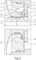
- Fig. 2 shows a sectional view of the bearing housing 1 not according to the invention, the bearing housing cover 2 and the sealing bush 3 engaging behind one another.
- the bearing housing cover 2 has a sealing contour in the form of a recess 18 on the bearing surface 11 and the sealing bush 3 on the stop surface 12 has a counter-sealing contour in the form of a spring 19. Both the recess 18 and the spring 19 are rotationally symmetrical with respect to the central axis 8, so that the sealing bush 3 can rotate with the shaft.
- the angle of intersection of the outer side wall 15 of the groove 14 and the inner side wall 16 of the groove 14 to the central axis 8 is not equal to zero.
- the lubricating oil in the groove 14 is discharged from the sealing area 13 on the outer side wall 15 and on the inner side wall 16, so that the amount of lubricating oil in the sealing area 13 is reduced and the sealing area 13 is thereby better sealed.
- Fig. 3 shows a view of the bearing housing cover 2 for the bearing housing 1 not according to the invention with the groove 14.
- the separating web 17 is arranged, which interrupts the groove 14 below the central axis 8.
- An annular flow of the lubricating oil in the groove 14 is interrupted by the separating web 17 and the lubricating oil can run out of the groove 14 laterally on the separating web 17.
- Fig. 4 is a view of the bearing housing cover 2 for the bearing housing 1 not according to the invention with the separating web 17 and with outflow channels 20 is shown.
- the outflow channels 20 are directed radially outwards and are arranged below the central axis 8.
- the outflow channels 20 connect the groove 14 and the bearing surface 11 of the bearing housing cover 2, so that the lubricating oil can drain out of the groove 14 more quickly.
- Fig. 5 shows a view of the bearing housing cover 2 for the bearing housing 1 not according to the invention with the separating web 17 and with a drain recess 21.
- the drain recess 21 is arranged below the central axis 8 and lies against the outer side wall 15 of the groove 14.
- the drain recess 21 has a smaller depth than the groove 14, so that the lubricating oil accumulated in the groove 14 can drain under gravity into the drain recess 21 and then onto the bearing surface 11 of the bearing housing cover 2.
- the drain recess 21 is not arranged around the central axis 8 so that no ring flow is supported in the drain recess 21 and a larger amount of the lubricating oil can thereby drain off.
- Fig. 6 shows a view of a bearing housing cover 22 for the bearing housing 1 according to the invention with the groove 14, which has a drain area 23.
- the drain area 23 is arranged below the central axis 8 and is extended radially outward from the central axis 8.
- the extended drain area 23 can advantageously reduce an annular flow in the groove 14 and the lubricating oil can drain from the groove 14 under the influence of gravity.
- the amount of lubricating oil in the groove 14 and consequently on the contact surface 11 can thus be reduced and the sealing area 13 between the bearing housing cover 22 and the sealing bush 3 can be sealed better.
Landscapes
- Engineering & Computer Science (AREA)
- General Engineering & Computer Science (AREA)
- Mechanical Engineering (AREA)
- Chemical & Material Sciences (AREA)
- Combustion & Propulsion (AREA)
- Supercharger (AREA)
- Sliding-Contact Bearings (AREA)
- Gasket Seals (AREA)
Description
- Die Erfindung betrifft ein Lagergehäuse mit einem Lagergehäusedeckel und einen Abgasturbolader mit einem solchen Lagergehäuse.
- In einem Abgasturbolader verbindet das Lagergehäuse ein Verdichtergehäuse zum Verdichten der zu Brennkammern der Brennzylinder strömenden Luft mit einem Turbinengehäuse zum Antreiben einer Welle mittels einer Abgasströmung. Das Lagergehäuse, das Verdichtergehäuse und das Turbinengehäuse sind durch die Welle miteinander verbunden. Das Turbinengehäuse und das Verdichtergehäuse sind mit einem Teilchenstrom belastet und müssen von dem schmierölaufnehmenden Lagergehäuse öldicht getrennt werden.
- Durch den Lagergehäusedeckel wird das Lagergehäuse von dem Verdichtergehäuse getrennt. Damit die Welle das Lagergehäuse mit dem Verdichtergehäuse verbinden kann, weist der Lagergehäusedeckel eine rotationssymmetrische Dichtungsausnehmung mit einer Mittelachse auf. In der Dichtungsausnehmung ist zumindest bereichsweise eine Dichtungsbuchse angeordnet, die eine Wellenausnehmung für die Welle aufweist und diese zu dem Verdichtergehäuse abdichtet. Die Dichtungsbuchse ist an einer Auflagefläche des Lagergehäusedeckels mit einer Anschlagfläche angeordnet und wird dadurch in Richtung des Verdichtergehäuses axial festgelegt. Auf der Auflagefläche des Lagergehäusedeckels ist des Weiteren eine von der Mittelachse beabstandete umlaufende Nut angeordnet.
- Bei hohen Drehzahlen herrscht in dem Verdichtergehäuse im Vergleich zu dem Lagergehäuse ein Überdruck, so dass das Schmieröl aus dem Lagergehäuse nicht in das Verdichtergehäuse entweichen kann. Fällt jedoch die Drehzahl und damit der Druck in dem Verdichtergehäuse, so kann das Schmieröl in das Verdichtergehäuse, insbesondere zwischen der Auflagefläche des Lagergehäuses und der Anschlagfläche der Dichtungsbuchse, entweichen.
- Aus dem Stand der Technik sind einige Lösungen für eine öldichte Abtrennung des Lagergehäuses von dem Verdichtergehäuse bereits bekannt. So beschreiben beispielsweise die Druckschriften
JP 721 441 A US 4,664,605 A zusätzliche Dichtungsscheiben, durch die das Schmieröl bereits vor dem Lagergehäusedeckel aufgefangen und in einen Innenraum des Lagergehäuses zurückgeleitet wird. Gelangt jedoch das Schmieröl zwischen die Dichtungsscheibe und den Lagergehäusedeckel, so kann das Schmieröl nicht mehr aufgefangen werden. - Die Druckschrift
EP 2 192 272 B1 beschreibt eine weitere Lösung zu dem oben beschriebenen Problem. - Die Aufgabe der vorliegenden Erfindung ist es, ein Lagergehäuse der oben genannten Gattung derart zu verbessern, dass insbesondere die Abdichtung in einem Dichtungsbereich zwischen der Auflagefläche des Lagergehäuses und der Anschlagfläche der Dichtungsbuchse verbessert wird.
- Diese Aufgabe wird erfindungsgemäß durch den Gegenstand der unabhängigen Ansprüche gelöst. Vorteilhafte Ausführungsformen sind Gegenstand der abhängigen Ansprüche.
- Die vorliegende Erfindung beruht auf dem allgemeinen Gedanken, dass eine Nut einen unterhalb einer Mittelachse angeordneten, von der Mittelachse radial nach außen ausgedehnten Ablaufbereich aufweist. Die Nut kann beispielsweise eiförmig sein oder in dem ausgedehnten Ablaufbereich spitz nach unten zulaufen. Der ausgedehnte Ablaufbereich kann vorteilhaft eine Ringströmung in der Nut reduzieren und das Schmieröl kann durch den Ablaufbereich aus der Nut unter Einwirkung der Schwerkraft ablaufen. Somit wird die Menge des Schmieröls in der Nut und folglich auf der Auflagefläche des Lagergehäuses reduziert und der Dichtungsbereich zwischen dem Lagergehäusedeckel und der Dichtungsbuchse besser abgedichtet.
- Bei einer vorteilhaften Weiterbildung der erfindungsgemäßen Lösung ist vorgesehen, dass die Nut wenigstens einen radial nach außen gerichteten, unter der Mittelachse angeordneten Abströmungskanal aufweist. Der Abströmungskanal verbindet die Nut und die Auflagefläche des Lagergehäusedeckels unterhalb der Mittelachse, so dass das Schmieröl aus der Nut schneller ablaufen kann.
- Der Abströmungskanal kann eine an die Strömung des Schmieröls in der Nut angepasste Form aufweisen. So kann der Abströmungskanal in seiner Längsrichtung eine abweichende Breite, eine abweichende Tiefe oder einen abweichenden Querschnitt aufweisen. Durch die Geometrie des Abströmungskanals können die Ablaufgeschwindigkeit sowie die Ablaufmenge des Schmieröls optimiert werden.
- Vorteilhafterweise ist vorgesehen, dass der Lagergehäusedeckel wenigstens eine unterhalb der Mittelachse angeordnete an einer äußeren Seitenwand der Nut anliegende Ablaufausnehmung aufweist. Die Ablaufausnehmung kann eine im Vergleich zu der Nut kleinere Tiefe aufweisen, so dass das in der Nut angesammelte Schmieröl unter der Schwerkraft in die Ablaufausnehmung und anschließend auf die Auflagefläche des Lagergehäusedeckels ablaufen kann. Die Ablaufausnehmung ist nicht umlaufend um die Mittelachse angeordnet, so dass keine Ringströmung in der Ablaufausnehmung möglich ist und dadurch eine größere Menge des Schmieröls ablaufen kann.
- Der Lagergehäusedeckel kann auch mehrere aneinander anliegende Ablaufausnehmungen aufweisen, wobei die Ablaufausnehmungen eine voneinander abweichende Tiefe, Breite und Länge aufweisen können. Die Tiefe, die Breite sowie die Länge der Ablaufausnehmungen können sich schrittweise verändern, so dass durch die Ablaufausnehmungen eine stufenartige Ablaufstruktur ausgeformt wird. Eine derartige stufenartige Ablaufstruktur kann die Ringströmung in der Nut verhindern, so dass das Ablaufen des Schmieröls aus der Nut verbessert und der Dichtungsbereich zwischen der Auflagefläche und der Anschlagfläche abgedichtet werden können.
- Vorteilhafterweise ist bei einer Weiterbildung der erfindungsgemäßen Lösung vorgesehen, dass ein Schnittwinkel zwischen der äußeren Seitenwand der Nut und/oder einer inneren Seitenwand der Nut und der Mittelachse von Null abweicht. Das Schmieröl in der Nut wird dadurch von der Mittelachse und somit von dem Dichtungsbereich abgeleitet, so dass die Menge des Schmieröls in der Nut reduziert wird.
- Die zu der Mittelachse geneigte innere Seitenwand der Nut vermindert ein Ablaufen des Schmieröls zu dem Dichtungsbereich und verbessert somit die Abdichtung zwischen der Auflagefläche und der Anschlagfläche. Durch die zu der Mittelachse geneigte äußere Seitenwand der Nut wird das in der Nut angesammelte Öl abgeleitet. Vorteilhafterweise wird bei einer derartig ausgestalteten äußeren Seitenwand das Ablaufen des Schmieröls auch durch die Ringströmung des Schmieröls in der Nut unterstütz.
- Sowohl der Schnittwinkel zwischen der Mittelachse und der inneren Seitenwand als auch der Schnittwinkel zwischen der Mittelachse und der äußeren Seitenwand können an das Strömungsverhalten des Schmieröls angepasst werden und sich voneinander unterscheiden.
- Vorteilhafterweise ist vorgesehen, dass eine Dichtkontur auf der Auflagefläche und eine Gegendichtkontur auf der Anschlagfläche vorgesehen sind, die insbesondere ineinander eingreifen, wobei die Dichtkontur und die Gegendichtkontur rotationssymmetrisch und beide zu der Mittelachse beabstandet angeordnet sind. Vorteilhafterweise können beispielsweise die Dichtkontur eine Ausnehmung und die Gegendichtkontur eine insbesondere komplementär dazu ausgebildete Feder sein. Die Konturen verhindern zusätzlich ein Ablaufen des Schmieröls in den Dichtungsbereich zwischen der Anschlagfläche und der Auflagefläche und verbessern die Abdichtung in dem Dichtungsbereich.
- Bei einer alternativen nicht erfindungsgemäßen Lösung ist vorgesehen, dass die Nut einen unterhalb der Mittelachse angeordneten Trennsteg aufweist, der die Nut unterbricht. Der Trennsteg verhindert die Ringströmung des Schmieröls in der Nut, so dass das Schmieröl aus der Nut ablaufen kann. Die Form des Trennstegs kann an das Strömungsverhalten des Schmieröls in der Nut angepasst sein. So kann der Trennsteg beispielsweise nach unten zugespitzt ausgeformt sein, um ein Ablaufen des Schmieröls unter der Einwirkung der Schwerkraft zu unterstützen.
- Vorteilhafterweise ist bei einer Weiterbildung der nicht erfindungsgemäßen Lösung vorgesehen, dass die Nut wenigstens einen radial nach außen gerichteten, unter der Mittelachse angeordneten Abströmungskanal aufweist, durch den das in der Nut angesammelte Schmieröl ablaufen kann. So kann durch den Trennsteg die Ringströmung des Schmieröls in der Nut unterbrochen werden und das an dem Trennsteg angesammelte Schmieröl durch den Abströmungskanal aus der Nut abgeleitet werden. Der Abströmungskanal kann dabei beispielsweise seitlich an dem Trennsteg angeordnet sein. Alternativ können auch zwei Abströmungskanäle jeweils seitlich an dem Trennsteg angeordnet sein.
- Der Abströmungskanal kann eine an das Strömungsverhalten des Schmieröls in der Nut angepasste Form aufweisen. So kann der Abströmungskanal in seiner Längsrichtung eine abweichende Breite, eine abweichende Tiefe oder einen abweichenden Querschnitt aufweisen. Durch die Geometrie des Abströmungskanals können die Ablaufgeschwindigkeit sowie die Ablaufmenge des Schmieröls optimiert werden.
- Vorteilhafterweise ist bei der nicht erfindungsgemäßen Lösung vorgesehen, dass der Lagergehäusedeckel wenigstens eine unterhalb der Mittelachse angeordnete an einer äußeren Seitenwand der Nut anliegende Ablaufausnehmung aufweist. Die Ablaufausnehmung kann eine im Vergleich zu der Nut kleinere Tiefe aufweisen, so dass das in der Nut angesammelte Schmieröl unter der Schwerkraft in die Ablaufausnehmung und anschließend auf die Auflagefläche des Lagergehäusedeckels ablaufen kann. Der Lagergehäusedeckel kann auch mehrere aneinander anliegende Ablaufausnehmungen aufweisen, wobei die Ablaufausnehmungen eine voneinander abweichende Tiefe, Breite und Länge aufweisen können. Der Trennsteg kann dabei in die Ablaufausnehmungen hineinragen, so dass auch in der jeweiligen Ablaufausnehmung die Ringströmung des Schmieröls unterbrochen wird.
- Bei einer vorteilhaften Weiterbildung der nicht erfindungsgemäßen Lösung ist vorgesehen, dass ein Schnittwinkel zwischen der äußeren Seitenwand der Nut und/oder einer inneren Seitenwand der Nut und der Mittelachse von Null abweicht. Das Schmieröl in der Nut kann so von der Mittelachse abgeleitet werden, so dass der Dichtungsbereich besser abgedichtet werden kann. Der Schnittwinkel zwischen der Mittelachse und der inneren Seitenwand kann sich von dem Schnittwinkel zwischen der Mittelachse und der äußeren Seitenwand unterscheiden, um das Strömungsverhalten des Schmieröls in der Nut optimieren zu können.
- Vorteilhafterweise ist vorgesehen, dass eine Dichtkontur auf der Auflagefläche und eine Gegendichtkontur auf der Anschlagfläche vorgesehen sind, wobei die Dichtkontur und die Gegendichtkontur beide rotationssymmetrisch und beide zu der Mittelachse beabstandet angeordnet sind. Beispielsweise können die Dichtkontur eine Ausnehmung und die Gegendichtkontur eine insbesondere komplementär darin eingreifende Feder sein.
- Die Erfindung betrifft auch einen Abgasturbolader mit einem Lagergehäuse nach der vorangegangenen Beschreibung zu der erfindungsgemäßen Lösung.
- Weitere wichtige Merkmale und Vorteile der Erfindung ergeben sich aus den Unteransprüchen, aus den Zeichnungen und aus der zugehörigen Figurenbeschreibung anhand der Zeichnungen.
- Es versteht sich, dass die vorstehend genannten und die nachstehend noch zu erläuternden Merkmale nicht nur in der jeweils angegebenen Kombination, sondern auch in anderen Kombinationen oder in Alleinstellung verwendbar sind, ohne den Rahmen der vorliegenden Erfindung zu verlassen.
- Bevorzugte Ausführungsbeispiele der Erfindung sind in den Zeichnungen dargestellt und werden in der nachfolgenden Beschreibung näher erläutert, wobei sich gleiche Bezugszeichen auf gleiche oder ähnliche oder funktional gleiche Komponenten beziehen.
- Es zeigen, jeweils schematisch
- Fig. 1
- eine Schnittansicht eines nicht erfindungsgemäßen Lagergehäuses mit einem Lagergehäusedeckel und mit einer Dichtungsbuchse;
- Fig. 2
- eine Schnittansicht eines nicht erfindungsgemäßen Lagergehäuses, wobei ein Lagergehäusedeckel und eine Dichtungsbuchse sich hintergreifen;
- Fig. 3
- eine Ansicht eines Lagergehäusedeckels eines nicht erfindungsgemäßen Lagergehäuses mit einer Nut, die durch einen Trennsteg unterbrochen ist;
- Fig. 4
- eine Ansicht eines Lagergehäusedeckels eines nicht erfindungsgemäßen Lagergehäuses mit einem Trennsteg und mit Abströmungskanälen;
- Fig. 5
- eine Ansicht eines Lagergehäusedeckels eines nicht erfindungsgemäßen Lagergehäuses mit einem Trennsteg und mit einer Ablaufausnehmung;
- Fig. 6
- eine Ansicht eines Lagergehäusedeckels eines erfindungsgemäßen Lagergehäuses mit einer Nut, die einen Ablaufbereich aufweist.
-
Fig. 1 zeigt eine Schnittansicht eines nicht erfindungsgemäßen Lagergehäuses 1 mit einem Lagergehäusedeckel 2 und mit einer Dichtungsbuchse 3. Durch den Lagergehäusedeckel 2 wird das Lagergehäuse 1 von einem Verdichter 4 getrennt. Zwischen dem Lagergehäusedeckel 2 und dem Lagergehäuse 1 sind eine Ringdichtung 5 sowie eine Axiallagerscheibe 6 angeordnet, die beidseitig jeweils eine Anlauffläche sowie eine Positionierungsausnehmung für eine Welle aufweist. - Durch eine rotationssymmetrische Dichtungsausnehmung 7 mit einer Mittelachse 8 kann die Welle das Lagergehäuse 1 mit dem Verdichter 4 verbinden. In der Dichtungsausnehmung 7 ist die Dichtungsbuchse 3 bereichsweise angeordnet und ist zu dem Lagergehäusedeckel 2 durch Ringdichtungen 9 abgedichtet. Die Dichtungsbuchse 3 weist eine Wellenausnehmung 10 für die Welle auf und dichtet das Lagergehäuse 1 zu dem Verdichter 4 ab.
- Die Dichtungsbuchse 3 ist mit einer Anschlagfläche 12 gegenüberliegend zu einer Auflagefläche 11 des Lagergehäusedeckels 2 angeordnet. Zwischen der Auflagefläche 11 und der Anschlagfläche 12 befinden sich ein Ringspalt und ein Dichtungsbereich 13, durch den insbesondere bei kleinen Drehzahlen das Schmieröl in den Verdichter 4 gelangen kann.
- Auf der Auflagefläche 11 des Lagergehäusedeckels 2 - was hier als "in die Auflagefläche 11 hineinragend" und als "in der Auflagefläche 11 ausgebildet" zu verstehen ist - ist des Weiteren eine die Mittelachse 8 beabstandet umlaufende Nut 14 angeordnet. Die Nut 14 weist eine äußere Seitenwand 15 und eine innere Seitenwand 16 auf, wobei ein Schnittwinkel der äußeren Seitenwand 15 zu der Mittelachse 8 und ein Schnittwinkel der inneren Seitenwand 16 zu der Mittelachse 8 in diesem Ausführungsbeispiel gleich Null, das heißt die Wände 15, 16 parallel zur Mittelachse 8, sind.
- Unterhalb der Mittelachse 8 weist die Nut 14 einen Trennsteg 17 auf, der die Nut 14 unterbricht. Durch den Trennsteg 17 kann eine Ringströmung des Schmieröls in der Nut 14 unterbrochen werden und das Schmieröl kann seitlich an dem Trennsteg 17 aus der Nut 14 ablaufen.
-
Fig. 2 zeigt eine Schnittansicht des nicht erfindungsgemäßen Lagergehäuses 1, wobei der Lagergehäusedeckel 2 und die Dichtungsbuchse 3 sich hintergreifen. - Der Lagergehäusedeckel 2 weist auf der Auflagefläche 11 eine Dichtkontur in Form einer Ausnehmung 18 und die Dichtungsbuchse 3 auf der Anschlagfläche 12 eine Gegendichtkontur in Form einer Feder 19 auf. Sowohl die Ausnehmung 18 als auch die Feder 19 sind rotationssymmetrisch zu der Mittelachse 8, so dass eine Rotation der Dichtungsbuchse 3 mit der Welle möglich wird.
- In diesem Ausführungsbeispiel ist der Schnittwinkel der äußeren Seitenwand 15 der Nut 14 und der inneren Seitenwand 16 der Nut 14 zu der Mittelachse 8 ungleich Null. Das Schmieröl in der Nut 14 wird an der äußeren Seitenwand 15 und an der inneren Seitenwand 16 von dem Dichtungsbereich 13 abgeleitet, so dass die Menge des Schmieröls in dem Dichtungsbereich 13 reduziert wird und dadurch der Dichtungsbereich 13 besser abgedichtet wird.
-
Fig. 3 zeigt eine Ansicht des Lagergehäusedeckels 2 für das nicht erfindungsgemäße Lagegehäuse 1 mit der Nut 14. In der Nut 14 ist der Trennsteg 17 angeordnet, der die Nut 14 unterhalb der Mittelachse 8 unterbricht. Durch den Trennsteg 17 wird eine Ringströmung des Schmieröls in der Nut 14 unterbrochen und das Schmieröl kann aus der Nut 14 seitlich an dem Trennsteg 17 ablaufen. - In
Fig. 4 ist eine Ansicht des Lagergehäusedeckels 2 für das nicht erfindungsgemäße Lagegehäuse 1 mit dem Trennsteg 17 und mit Abströmungskanälen 20 gezeigt. Die Abströmungskanäle 20 sind radial nach außen gerichtet und unter der Mittelachse 8 angeordnet. Die Abströmungskanäle 20 verbinden die Nut 14 und die Auflagefläche 11 des Lagergehäusedeckels 2, so dass das Schmieröl aus der Nut 14 schneller ablaufen kann. -
Fig. 5 zeigt eine Ansicht des Lagergehäusedeckels 2 für das nicht erfindungsgemäße Lagegehäuse 1 mit dem Trennsteg 17 und mit einer Ablaufausnehmung 21. Die Ablaufausnehmung 21 ist unterhalb der Mittelachse 8 angeordnet und liegt an der äußeren Seitenwand 15 der Nut 14 an. Die Ablaufausnehmung 21 weist eine kleinere Tiefe als die Nut 14 auf, so dass das in der Nut 14 angesammelte Schmieröl unter der Schwerkraft in die Ablaufausnehmung 21 und anschließend auf die Auflagefläche 11 des Lagergehäusedeckels 2 ablaufen kann. Die Ablaufausnehmung 21 ist um die Mittelachse 8 nicht umlaufend angeordnet, so dass keine Ringströmung in der Ablaufausnehmung 21 unterstützt wird und dadurch eine größere Menge des Schmieröls ablaufen kann. -
Fig. 6 zeigt eine Ansicht eines Lagergehäusedeckels 22 für das erfindungsgemäße Lagegehäuse 1 mit der Nut 14, die einen Ablaufbereich 23 aufweist. Der Ablaufbereich 23 ist unterhalb der Mittelachse 8 anordnet und ist von der Mittelachse 8 radial nach außen ausgedehnt. Der ausgedehnte Ablaufbereich 23 kann vorteilhaft eine Ringströmung in der Nut 14 reduzieren und das Schmieröl kann aus der Nut 14 unter Einwirkung der Schwerkraft ablaufen. Die Menge des Schmieröls in der Nut 14 und folglich auf der Auflagefläche 11 können somit reduziert werden und der Dichtungsbereich 13 zwischen dem Lagergehäusedeckel 22 und der Dichtungsbuchse 3 kann besser abgedichtet werden.
Claims (7)
- Lagergehäuse (1) mit einem Lagergehäusedeckel (22) für einen Abgasturbolader,- wobei der Lagergehäusedeckel (22) an dem Lagergehäuse (1) angeordnet ist,- wobei der Lagergehäusedeckel (22) eine durchdringende rotationssymmetrische Dichtungsausnehmung (7) mit einer Mittelachse (8) aufweist,- wobei in der Dichtungsausnehmung (7) eine Dichtungsbuchse (3) zumindest bereichsweise angeordnet ist,- wobei die Dichtungsbuchse (3) eine durchdringende zu der Mittelachse (8) rotationssymmetrische Wellenausnehmung (10) für eine Welle aufweist,- wobei der Lagergehäusedeckel (22) eine dem Lagergehäuse (1) zugewandte sich von der Mittelachse (8) radial erstreckende Auflagefläche (11) aufweist, die einer Anschlagfläche (12) der Dichtungsbuchse (3) gegenüberliegt,- wobei der Lagergehäusedeckel (22) in der Auflagefläche (11) eine zur Mittelachse (8) radial beabstandete und zumindest teilweise umlaufende Nut (14) aufweist,dadurch gekennzeichnet,
dass die Nut (14) einen unterhalb der Mittelachse (8) angeordneten, von der Mittelachse (8) radial nach außen ausgedehnten Ablaufbereich (23) aufweist, so dass die Nut eiförmig oder in dem ausgedehnten Ablaufbereich spitz nach unten zuläuft, um das in der Nut (14) angesammelte Schmieröl ablaufen zu lassen. - Lagergehäuse nach Anspruch 1,
dadurch gekennzeichnet,
dass die Nut (14) wenigstens einen radial nach außen gerichteten, unter der Mittelachse (8) angeordneten Abströmungskanal (20) aufweist, durch den das in der Nut (14) angesammelte Schmieröl ablaufen kann. - Lagergehäuse nach einem der vorangehenden Ansprüche,
dadurch gekennzeichnet,
dass der Lagergehäusedeckel (22) wenigstens eine unterhalb der Mittelachse (8) angeordnete an einer äußeren Seitenwand (15) der Nut (14) anliegende Ablaufausnehmung (21) aufweist. - Lagergehäuse nach einem der vorangehenden Ansprüche,
dadurch gekennzeichnet,
dass ein Schnittwinkel zwischen der äußeren Seitenwand (15) der Nut (14) und/oder einer inneren Seitenwand (16) der Nut (14) und der Mittelachse (8) von Null abweicht. - Lagergehäuse nach einem der vorangehenden Ansprüche,
dadurch gekennzeichnet,
dass auf der Auflagefläche (11) eine Dichtkontur und auf der Anschlagfläche (12) eine Gegendichtkontur angeordnet sind, die beide rotationssymmetrisch und zur Mittelachse (8) beabstandet angeordnet sind. - Lagergehäuse nach Anspruch 5,
dadurch gekennzeichnet,
dass die Dichtkontur eine Ausnehmung (18) und die Gegendichtkontur eine insbesondere komplementär dazu ausgebildete Feder (19) sind. - Abgasturbolader mit einem Lagergehäuse (1) nach einem der vorhergehenden Ansprüche.
Priority Applications (1)
| Application Number | Priority Date | Filing Date | Title |
|---|---|---|---|
| EP20162402.0A EP3699405B1 (de) | 2017-02-20 | 2018-02-02 | Lagergehäuse und ein abgasturbolader mit einem solchen gehäuse |
Applications Claiming Priority (1)
| Application Number | Priority Date | Filing Date | Title |
|---|---|---|---|
| DE102017202687.1A DE102017202687A1 (de) | 2017-02-20 | 2017-02-20 | Lagergehäuse und ein Abgasturoblader mit einem solchen Gehäuse |
Related Child Applications (2)
| Application Number | Title | Priority Date | Filing Date |
|---|---|---|---|
| EP20162402.0A Division-Into EP3699405B1 (de) | 2017-02-20 | 2018-02-02 | Lagergehäuse und ein abgasturbolader mit einem solchen gehäuse |
| EP20162402.0A Division EP3699405B1 (de) | 2017-02-20 | 2018-02-02 | Lagergehäuse und ein abgasturbolader mit einem solchen gehäuse |
Publications (3)
| Publication Number | Publication Date |
|---|---|
| EP3392471A2 EP3392471A2 (de) | 2018-10-24 |
| EP3392471A3 EP3392471A3 (de) | 2019-01-23 |
| EP3392471B1 true EP3392471B1 (de) | 2020-05-27 |
Family
ID=61157099
Family Applications (2)
| Application Number | Title | Priority Date | Filing Date |
|---|---|---|---|
| EP18154911.4A Not-in-force EP3392471B1 (de) | 2017-02-20 | 2018-02-02 | Lagergehäuse und ein abgasturbolader mit einem solchen gehäuse |
| EP20162402.0A Active EP3699405B1 (de) | 2017-02-20 | 2018-02-02 | Lagergehäuse und ein abgasturbolader mit einem solchen gehäuse |
Family Applications After (1)
| Application Number | Title | Priority Date | Filing Date |
|---|---|---|---|
| EP20162402.0A Active EP3699405B1 (de) | 2017-02-20 | 2018-02-02 | Lagergehäuse und ein abgasturbolader mit einem solchen gehäuse |
Country Status (4)
| Country | Link |
|---|---|
| US (1) | US10508564B2 (de) |
| EP (2) | EP3392471B1 (de) |
| CN (1) | CN108457751B (de) |
| DE (1) | DE102017202687A1 (de) |
Families Citing this family (6)
| Publication number | Priority date | Publication date | Assignee | Title |
|---|---|---|---|---|
| DE102017121316A1 (de) * | 2017-09-14 | 2019-03-14 | Man Diesel & Turbo Se | Turbolader |
| US10900380B2 (en) * | 2017-12-13 | 2021-01-26 | Borgwarner Inc. | Recirculation stall in compressor insert or backplate |
| DE102019101258A1 (de) * | 2019-01-18 | 2020-07-23 | Bayerische Motoren Werke Aktiengesellschaft | Abgasturbolader |
| DE102019209217A1 (de) * | 2019-06-26 | 2020-12-31 | BMTS Technology GmbH & Co. KG | Ladeeinrichtung |
| DE102020129864B4 (de) * | 2020-11-12 | 2025-07-24 | Hanon Systems | Vorrichtung zum Verdichten eines gasförmigen Fluids |
| JP7460018B2 (ja) * | 2021-04-23 | 2024-04-02 | 株式会社Ihi | 過給機 |
Family Cites Families (23)
| Publication number | Priority date | Publication date | Assignee | Title |
|---|---|---|---|---|
| US4609334A (en) * | 1982-12-23 | 1986-09-02 | Copeland Corporation | Scroll-type machine with rotation controlling means and specific wrap shape |
| JPH0216037Y2 (de) | 1984-12-20 | 1990-05-01 | ||
| JPH0721441A (ja) | 1993-06-30 | 1995-01-24 | Kyowa Giken Kk | 釣り銭精算装置 |
| JPH07217441A (ja) | 1994-02-02 | 1995-08-15 | Taiho Kogyo Co Ltd | ターボチャージャの非接触シール装置 |
| DE102004011251A1 (de) * | 2004-03-09 | 2005-10-13 | Daimlerchrysler Ag | Verdichter, Brennkraftmaschine mit einem Verdichter und Verfahren zum Betrieb einer Brennkraftmaschine |
| US20070092387A1 (en) * | 2005-10-21 | 2007-04-26 | Borgwarner Inc. | Oil discharge assembly for a turbocharger |
| CN100559019C (zh) * | 2007-06-18 | 2009-11-11 | 寿光市康跃增压器有限公司 | 一种废气涡轮增压器核心转子装置 |
| EP2192272B1 (de) | 2008-11-28 | 2011-01-12 | ABB Turbo Systems AG | Vorrichtung zum Abdichten eines Lagergehäuses eines Abgasturboladers |
| DE102009058068A1 (de) * | 2009-12-14 | 2011-06-16 | Bosch Mahle Turbo Systems Gmbh & Co. Kg | Lagergehäuse einer Ladeeinrichtung |
| DE102010003796A1 (de) | 2010-04-09 | 2011-10-13 | Abb Turbo Systems Ag | Wellenabdichtung |
| DE102010025614A1 (de) * | 2010-06-30 | 2012-01-05 | Daimler Ag | Abgasturbolader |
| WO2012027183A2 (en) * | 2010-08-24 | 2012-03-01 | Borgwarner Inc. | Bearing housing of an exhaust-gas turbocharger |
| JP5522113B2 (ja) | 2011-04-13 | 2014-06-18 | 株式会社豊田自動織機 | ターボチャージャ |
| CN102400944A (zh) * | 2011-07-13 | 2012-04-04 | 康跃科技股份有限公司 | 涡轮增压器压气机端双环密封装置 |
| WO2013162703A1 (en) * | 2012-04-24 | 2013-10-31 | Borgwarner Inc. | Tapered-land thrust bearing for turbochargers |
| KR20150013683A (ko) * | 2012-05-16 | 2015-02-05 | 보르그워너 인코퍼레이티드 | 플린저 오일 씰 및 이를 포함하는 터보차저 |
| WO2014004245A1 (en) * | 2012-06-25 | 2014-01-03 | Borgwarner Inc. | Exhaust-gas turbocharger |
| DE102013202841A1 (de) * | 2013-02-21 | 2014-08-21 | Bosch Mahle Turbo Systems Gmbh & Co. Kg | Abgasturbolader |
| CN104594961B (zh) * | 2014-04-24 | 2016-06-15 | 宁波摩多汽车零部件有限公司 | 一种涡轮增压器的压气机端密封结构 |
| GB2534688B (en) * | 2014-12-23 | 2021-01-27 | Cummins Ltd | Bearing assembly support |
| DE112016001408T5 (de) | 2015-03-26 | 2017-12-07 | Borgwarner Inc. | Ölabweiser mit Ölführung |
| WO2017014156A1 (ja) * | 2015-07-22 | 2017-01-26 | 株式会社Ihi | オイルシール構造、および、過給機 |
| DE102015119602A1 (de) | 2015-11-13 | 2017-05-18 | Abb Turbo Systems Ag | Wellendichtung |
-
2017
- 2017-02-20 DE DE102017202687.1A patent/DE102017202687A1/de not_active Withdrawn
-
2018
- 2018-02-02 EP EP18154911.4A patent/EP3392471B1/de not_active Not-in-force
- 2018-02-02 EP EP20162402.0A patent/EP3699405B1/de active Active
- 2018-02-06 CN CN201810117959.1A patent/CN108457751B/zh not_active Expired - Fee Related
- 2018-02-19 US US15/899,357 patent/US10508564B2/en not_active Expired - Fee Related
Also Published As
| Publication number | Publication date |
|---|---|
| EP3392471A2 (de) | 2018-10-24 |
| EP3699405A1 (de) | 2020-08-26 |
| EP3392471A3 (de) | 2019-01-23 |
| CN108457751A (zh) | 2018-08-28 |
| EP3699405B1 (de) | 2022-07-06 |
| DE102017202687A1 (de) | 2018-08-23 |
| US10508564B2 (en) | 2019-12-17 |
| US20180238191A1 (en) | 2018-08-23 |
| CN108457751B (zh) | 2021-10-15 |
Similar Documents
| Publication | Publication Date | Title |
|---|---|---|
| EP3392471B1 (de) | Lagergehäuse und ein abgasturbolader mit einem solchen gehäuse | |
| EP1880090B1 (de) | Vorrichtung zum reinigen von gas beim entlüften eines kurbelgehäuses | |
| DE3828363C2 (de) | ||
| EP1394451B1 (de) | Wellenabdichtung für Turbolader | |
| DE102014210360B4 (de) | Nockenwellenverstellvorrichtung | |
| WO2012107118A1 (de) | Labyrinthdichtung eines radialwälzlagers mit radialflansch | |
| DE3048101C2 (de) | ||
| EP1327802B1 (de) | Hydraulische Dichtungsanordnung | |
| DE112017004896B4 (de) | Lagerstruktur und Turbolader | |
| DE69819293T2 (de) | Hydraulikdichtung | |
| EP1386100A1 (de) | Anordnung mit einem einem wellenlager zugeordneten abschleuderring und einer einem dichtspalt zugeordneten dichtung | |
| DE112018002160T5 (de) | Zentrifugalkompressor | |
| EP2420651B1 (de) | Lageranordnung für die Verdichterseite eines Turboladers einer Verbrennungskraftmaschine | |
| DE69026045T2 (de) | Flüssigkeitsentgasungspumpe | |
| DE3406963A1 (de) | Zweiteiliges gehaeuse mit oelfoerderschmierung | |
| WO2018149716A1 (de) | Ölabscheider mit geteilter antriebskammer | |
| WO2014131413A1 (de) | Dichtungsanordnung für eine turboladerwelle eines abgasturboladers | |
| DE112016003653B4 (de) | Lagerstruktur und Turbolader | |
| EP3224480B1 (de) | Verdichter mit einem dichtkanal | |
| DE69820536T2 (de) | Lagerkonstruktion für einen Turbolader | |
| DE202016106867U1 (de) | Ölabscheider mit Wellenlagerung zwischen Antriebs- und Abscheidekammer | |
| DE102018222511A1 (de) | Brennkraftmaschine | |
| CH703516B1 (de) | Turbomaschine. | |
| WO2013182306A1 (de) | Hydraulische dichtungsanordnung | |
| DE102007016425A1 (de) | Ölabscheider für CO2-Kälteanlagen |
Legal Events
| Date | Code | Title | Description |
|---|---|---|---|
| PUAI | Public reference made under article 153(3) epc to a published international application that has entered the european phase |
Free format text: ORIGINAL CODE: 0009012 |
|
| STAA | Information on the status of an ep patent application or granted ep patent |
Free format text: STATUS: THE APPLICATION HAS BEEN PUBLISHED |
|
| AK | Designated contracting states |
Kind code of ref document: A2 Designated state(s): AL AT BE BG CH CY CZ DE DK EE ES FI FR GB GR HR HU IE IS IT LI LT LU LV MC MK MT NL NO PL PT RO RS SE SI SK SM TR |
|
| AX | Request for extension of the european patent |
Extension state: BA ME |
|
| RIN1 | Information on inventor provided before grant (corrected) |
Inventor name: KUHNE, OLIVER Inventor name: KLEINSCHMIDT, RUEDIGER Inventor name: STETTER, FRIEDER Inventor name: HENZLER, SIMON Inventor name: SCHMITT, STEFFEN Inventor name: HASLINGER, FABIAN |
|
| PUAL | Search report despatched |
Free format text: ORIGINAL CODE: 0009013 |
|
| AK | Designated contracting states |
Kind code of ref document: A3 Designated state(s): AL AT BE BG CH CY CZ DE DK EE ES FI FR GB GR HR HU IE IS IT LI LT LU LV MC MK MT NL NO PL PT RO RS SE SI SK SM TR |
|
| AX | Request for extension of the european patent |
Extension state: BA ME |
|
| RIC1 | Information provided on ipc code assigned before grant |
Ipc: F01D 25/16 20060101AFI20181217BHEP Ipc: F02C 6/12 20060101ALI20181217BHEP Ipc: F01D 25/18 20060101ALN20181217BHEP |
|
| STAA | Information on the status of an ep patent application or granted ep patent |
Free format text: STATUS: REQUEST FOR EXAMINATION WAS MADE |
|
| 17P | Request for examination filed |
Effective date: 20190613 |
|
| RBV | Designated contracting states (corrected) |
Designated state(s): AL AT BE BG CH CY CZ DE DK EE ES FI FR GB GR HR HU IE IS IT LI LT LU LV MC MK MT NL NO PL PT RO RS SE SI SK SM TR |
|
| GRAP | Despatch of communication of intention to grant a patent |
Free format text: ORIGINAL CODE: EPIDOSNIGR1 |
|
| RIC1 | Information provided on ipc code assigned before grant |
Ipc: F02C 6/12 20060101ALI20191127BHEP Ipc: F01D 25/16 20060101AFI20191127BHEP Ipc: F01D 25/18 20060101ALN20191127BHEP |
|
| STAA | Information on the status of an ep patent application or granted ep patent |
Free format text: STATUS: GRANT OF PATENT IS INTENDED |
|
| INTG | Intention to grant announced |
Effective date: 20200102 |
|
| GRAS | Grant fee paid |
Free format text: ORIGINAL CODE: EPIDOSNIGR3 |
|
| GRAA | (expected) grant |
Free format text: ORIGINAL CODE: 0009210 |
|
| STAA | Information on the status of an ep patent application or granted ep patent |
Free format text: STATUS: THE PATENT HAS BEEN GRANTED |
|
| AK | Designated contracting states |
Kind code of ref document: B1 Designated state(s): AL AT BE BG CH CY CZ DE DK EE ES FI FR GB GR HR HU IE IS IT LI LT LU LV MC MK MT NL NO PL PT RO RS SE SI SK SM TR |
|
| REG | Reference to a national code |
Ref country code: GB Ref legal event code: FG4D Free format text: NOT ENGLISH |
|
| REG | Reference to a national code |
Ref country code: CH Ref legal event code: EP |
|
| REG | Reference to a national code |
Ref country code: DE Ref legal event code: R096 Ref document number: 502018001501 Country of ref document: DE |
|
| REG | Reference to a national code |
Ref country code: AT Ref legal event code: REF Ref document number: 1274768 Country of ref document: AT Kind code of ref document: T Effective date: 20200615 |
|
| REG | Reference to a national code |
Ref country code: LT Ref legal event code: MG4D |
|
| PG25 | Lapsed in a contracting state [announced via postgrant information from national office to epo] |
Ref country code: PT Free format text: LAPSE BECAUSE OF FAILURE TO SUBMIT A TRANSLATION OF THE DESCRIPTION OR TO PAY THE FEE WITHIN THE PRESCRIBED TIME-LIMIT Effective date: 20200928 Ref country code: NO Free format text: LAPSE BECAUSE OF FAILURE TO SUBMIT A TRANSLATION OF THE DESCRIPTION OR TO PAY THE FEE WITHIN THE PRESCRIBED TIME-LIMIT Effective date: 20200827 Ref country code: GR Free format text: LAPSE BECAUSE OF FAILURE TO SUBMIT A TRANSLATION OF THE DESCRIPTION OR TO PAY THE FEE WITHIN THE PRESCRIBED TIME-LIMIT Effective date: 20200828 Ref country code: IS Free format text: LAPSE BECAUSE OF FAILURE TO SUBMIT A TRANSLATION OF THE DESCRIPTION OR TO PAY THE FEE WITHIN THE PRESCRIBED TIME-LIMIT Effective date: 20200927 Ref country code: SE Free format text: LAPSE BECAUSE OF FAILURE TO SUBMIT A TRANSLATION OF THE DESCRIPTION OR TO PAY THE FEE WITHIN THE PRESCRIBED TIME-LIMIT Effective date: 20200527 Ref country code: LT Free format text: LAPSE BECAUSE OF FAILURE TO SUBMIT A TRANSLATION OF THE DESCRIPTION OR TO PAY THE FEE WITHIN THE PRESCRIBED TIME-LIMIT Effective date: 20200527 Ref country code: FI Free format text: LAPSE BECAUSE OF FAILURE TO SUBMIT A TRANSLATION OF THE DESCRIPTION OR TO PAY THE FEE WITHIN THE PRESCRIBED TIME-LIMIT Effective date: 20200527 |
|
| REG | Reference to a national code |
Ref country code: NL Ref legal event code: MP Effective date: 20200527 |
|
| PG25 | Lapsed in a contracting state [announced via postgrant information from national office to epo] |
Ref country code: BG Free format text: LAPSE BECAUSE OF FAILURE TO SUBMIT A TRANSLATION OF THE DESCRIPTION OR TO PAY THE FEE WITHIN THE PRESCRIBED TIME-LIMIT Effective date: 20200827 Ref country code: LV Free format text: LAPSE BECAUSE OF FAILURE TO SUBMIT A TRANSLATION OF THE DESCRIPTION OR TO PAY THE FEE WITHIN THE PRESCRIBED TIME-LIMIT Effective date: 20200527 Ref country code: RS Free format text: LAPSE BECAUSE OF FAILURE TO SUBMIT A TRANSLATION OF THE DESCRIPTION OR TO PAY THE FEE WITHIN THE PRESCRIBED TIME-LIMIT Effective date: 20200527 Ref country code: HR Free format text: LAPSE BECAUSE OF FAILURE TO SUBMIT A TRANSLATION OF THE DESCRIPTION OR TO PAY THE FEE WITHIN THE PRESCRIBED TIME-LIMIT Effective date: 20200527 |
|
| PG25 | Lapsed in a contracting state [announced via postgrant information from national office to epo] |
Ref country code: AL Free format text: LAPSE BECAUSE OF FAILURE TO SUBMIT A TRANSLATION OF THE DESCRIPTION OR TO PAY THE FEE WITHIN THE PRESCRIBED TIME-LIMIT Effective date: 20200527 Ref country code: NL Free format text: LAPSE BECAUSE OF FAILURE TO SUBMIT A TRANSLATION OF THE DESCRIPTION OR TO PAY THE FEE WITHIN THE PRESCRIBED TIME-LIMIT Effective date: 20200527 |
|
| PG25 | Lapsed in a contracting state [announced via postgrant information from national office to epo] |
Ref country code: DK Free format text: LAPSE BECAUSE OF FAILURE TO SUBMIT A TRANSLATION OF THE DESCRIPTION OR TO PAY THE FEE WITHIN THE PRESCRIBED TIME-LIMIT Effective date: 20200527 Ref country code: ES Free format text: LAPSE BECAUSE OF FAILURE TO SUBMIT A TRANSLATION OF THE DESCRIPTION OR TO PAY THE FEE WITHIN THE PRESCRIBED TIME-LIMIT Effective date: 20200527 Ref country code: RO Free format text: LAPSE BECAUSE OF FAILURE TO SUBMIT A TRANSLATION OF THE DESCRIPTION OR TO PAY THE FEE WITHIN THE PRESCRIBED TIME-LIMIT Effective date: 20200527 Ref country code: CZ Free format text: LAPSE BECAUSE OF FAILURE TO SUBMIT A TRANSLATION OF THE DESCRIPTION OR TO PAY THE FEE WITHIN THE PRESCRIBED TIME-LIMIT Effective date: 20200527 Ref country code: IT Free format text: LAPSE BECAUSE OF FAILURE TO SUBMIT A TRANSLATION OF THE DESCRIPTION OR TO PAY THE FEE WITHIN THE PRESCRIBED TIME-LIMIT Effective date: 20200527 Ref country code: EE Free format text: LAPSE BECAUSE OF FAILURE TO SUBMIT A TRANSLATION OF THE DESCRIPTION OR TO PAY THE FEE WITHIN THE PRESCRIBED TIME-LIMIT Effective date: 20200527 Ref country code: SM Free format text: LAPSE BECAUSE OF FAILURE TO SUBMIT A TRANSLATION OF THE DESCRIPTION OR TO PAY THE FEE WITHIN THE PRESCRIBED TIME-LIMIT Effective date: 20200527 |
|
| PG25 | Lapsed in a contracting state [announced via postgrant information from national office to epo] |
Ref country code: SK Free format text: LAPSE BECAUSE OF FAILURE TO SUBMIT A TRANSLATION OF THE DESCRIPTION OR TO PAY THE FEE WITHIN THE PRESCRIBED TIME-LIMIT Effective date: 20200527 Ref country code: PL Free format text: LAPSE BECAUSE OF FAILURE TO SUBMIT A TRANSLATION OF THE DESCRIPTION OR TO PAY THE FEE WITHIN THE PRESCRIBED TIME-LIMIT Effective date: 20200527 |
|
| REG | Reference to a national code |
Ref country code: DE Ref legal event code: R097 Ref document number: 502018001501 Country of ref document: DE |
|
| PLBE | No opposition filed within time limit |
Free format text: ORIGINAL CODE: 0009261 |
|
| STAA | Information on the status of an ep patent application or granted ep patent |
Free format text: STATUS: NO OPPOSITION FILED WITHIN TIME LIMIT |
|
| 26N | No opposition filed |
Effective date: 20210302 |
|
| PG25 | Lapsed in a contracting state [announced via postgrant information from national office to epo] |
Ref country code: SI Free format text: LAPSE BECAUSE OF FAILURE TO SUBMIT A TRANSLATION OF THE DESCRIPTION OR TO PAY THE FEE WITHIN THE PRESCRIBED TIME-LIMIT Effective date: 20200527 |
|
| PG25 | Lapsed in a contracting state [announced via postgrant information from national office to epo] |
Ref country code: MC Free format text: LAPSE BECAUSE OF FAILURE TO SUBMIT A TRANSLATION OF THE DESCRIPTION OR TO PAY THE FEE WITHIN THE PRESCRIBED TIME-LIMIT Effective date: 20200527 |
|
| REG | Reference to a national code |
Ref country code: BE Ref legal event code: MM Effective date: 20210228 |
|
| PG25 | Lapsed in a contracting state [announced via postgrant information from national office to epo] |
Ref country code: CH Free format text: LAPSE BECAUSE OF NON-PAYMENT OF DUE FEES Effective date: 20210228 Ref country code: LU Free format text: LAPSE BECAUSE OF NON-PAYMENT OF DUE FEES Effective date: 20210202 Ref country code: LI Free format text: LAPSE BECAUSE OF NON-PAYMENT OF DUE FEES Effective date: 20210228 |
|
| REG | Reference to a national code |
Ref country code: DE Ref legal event code: R082 Ref document number: 502018001501 Country of ref document: DE |
|
| PG25 | Lapsed in a contracting state [announced via postgrant information from national office to epo] |
Ref country code: IE Free format text: LAPSE BECAUSE OF NON-PAYMENT OF DUE FEES Effective date: 20210202 |
|
| PGFP | Annual fee paid to national office [announced via postgrant information from national office to epo] |
Ref country code: GB Payment date: 20220223 Year of fee payment: 5 Ref country code: DE Payment date: 20220217 Year of fee payment: 5 |
|
| PGFP | Annual fee paid to national office [announced via postgrant information from national office to epo] |
Ref country code: FR Payment date: 20220216 Year of fee payment: 5 |
|
| PG25 | Lapsed in a contracting state [announced via postgrant information from national office to epo] |
Ref country code: BE Free format text: LAPSE BECAUSE OF NON-PAYMENT OF DUE FEES Effective date: 20210228 |
|
| PG25 | Lapsed in a contracting state [announced via postgrant information from national office to epo] |
Ref country code: CY Free format text: LAPSE BECAUSE OF FAILURE TO SUBMIT A TRANSLATION OF THE DESCRIPTION OR TO PAY THE FEE WITHIN THE PRESCRIBED TIME-LIMIT Effective date: 20200527 |
|
| PG25 | Lapsed in a contracting state [announced via postgrant information from national office to epo] |
Ref country code: HU Free format text: LAPSE BECAUSE OF FAILURE TO SUBMIT A TRANSLATION OF THE DESCRIPTION OR TO PAY THE FEE WITHIN THE PRESCRIBED TIME-LIMIT; INVALID AB INITIO Effective date: 20180202 |
|
| REG | Reference to a national code |
Ref country code: DE Ref legal event code: R119 Ref document number: 502018001501 Country of ref document: DE |
|
| GBPC | Gb: european patent ceased through non-payment of renewal fee |
Effective date: 20230202 |
|
| PG25 | Lapsed in a contracting state [announced via postgrant information from national office to epo] |
Ref country code: GB Free format text: LAPSE BECAUSE OF NON-PAYMENT OF DUE FEES Effective date: 20230202 |
|
| PG25 | Lapsed in a contracting state [announced via postgrant information from national office to epo] |
Ref country code: GB Free format text: LAPSE BECAUSE OF NON-PAYMENT OF DUE FEES Effective date: 20230202 Ref country code: FR Free format text: LAPSE BECAUSE OF NON-PAYMENT OF DUE FEES Effective date: 20230228 Ref country code: DE Free format text: LAPSE BECAUSE OF NON-PAYMENT OF DUE FEES Effective date: 20230901 |
|
| REG | Reference to a national code |
Ref country code: AT Ref legal event code: MM01 Ref document number: 1274768 Country of ref document: AT Kind code of ref document: T Effective date: 20230202 |
|
| PG25 | Lapsed in a contracting state [announced via postgrant information from national office to epo] |
Ref country code: AT Free format text: LAPSE BECAUSE OF NON-PAYMENT OF DUE FEES Effective date: 20230202 |
|
| PG25 | Lapsed in a contracting state [announced via postgrant information from national office to epo] |
Ref country code: MK Free format text: LAPSE BECAUSE OF FAILURE TO SUBMIT A TRANSLATION OF THE DESCRIPTION OR TO PAY THE FEE WITHIN THE PRESCRIBED TIME-LIMIT Effective date: 20200527 Ref country code: AT Free format text: LAPSE BECAUSE OF NON-PAYMENT OF DUE FEES Effective date: 20230202 |
|
| PG25 | Lapsed in a contracting state [announced via postgrant information from national office to epo] |
Ref country code: MT Free format text: LAPSE BECAUSE OF FAILURE TO SUBMIT A TRANSLATION OF THE DESCRIPTION OR TO PAY THE FEE WITHIN THE PRESCRIBED TIME-LIMIT Effective date: 20200527 |
|
| PG25 | Lapsed in a contracting state [announced via postgrant information from national office to epo] |
Ref country code: TR Free format text: LAPSE BECAUSE OF FAILURE TO SUBMIT A TRANSLATION OF THE DESCRIPTION OR TO PAY THE FEE WITHIN THE PRESCRIBED TIME-LIMIT Effective date: 20200527 |
|
| PGFP | Annual fee paid to national office [announced via postgrant information from national office to epo] |
Ref country code: AT Payment date: 20260410 Year of fee payment: 5 |