EP3392533A1 - Dichtungsvorrichtung - Google Patents
Dichtungsvorrichtung Download PDFInfo
- Publication number
- EP3392533A1 EP3392533A1 EP16875263.2A EP16875263A EP3392533A1 EP 3392533 A1 EP3392533 A1 EP 3392533A1 EP 16875263 A EP16875263 A EP 16875263A EP 3392533 A1 EP3392533 A1 EP 3392533A1
- Authority
- EP
- European Patent Office
- Prior art keywords
- ring
- surface portion
- mounting groove
- contact
- sealing
- Prior art date
- Legal status (The legal status is an assumption and is not a legal conclusion. Google has not performed a legal analysis and makes no representation as to the accuracy of the status listed.)
- Granted
Links
- 238000007789 sealing Methods 0.000 title claims abstract description 60
- 230000002093 peripheral effect Effects 0.000 claims abstract description 32
- 239000012530 fluid Substances 0.000 claims description 18
- 238000003780 insertion Methods 0.000 description 6
- 230000037431 insertion Effects 0.000 description 6
- 230000000694 effects Effects 0.000 description 5
- 238000010586 diagram Methods 0.000 description 3
- 230000001154 acute effect Effects 0.000 description 2
- 238000000034 method Methods 0.000 description 2
- 239000011347 resin Substances 0.000 description 2
- 229920005989 resin Polymers 0.000 description 2
- 239000004677 Nylon Substances 0.000 description 1
- 230000015556 catabolic process Effects 0.000 description 1
- 238000006731 degradation reaction Methods 0.000 description 1
- 238000005516 engineering process Methods 0.000 description 1
- 238000002347 injection Methods 0.000 description 1
- 239000007924 injection Substances 0.000 description 1
- 230000013011 mating Effects 0.000 description 1
- 229920001778 nylon Polymers 0.000 description 1
- 239000004810 polytetrafluoroethylene Substances 0.000 description 1
- 229920001343 polytetrafluoroethylene Polymers 0.000 description 1
Images


Classifications
-
- F—MECHANICAL ENGINEERING; LIGHTING; HEATING; WEAPONS; BLASTING
- F16—ENGINEERING ELEMENTS AND UNITS; GENERAL MEASURES FOR PRODUCING AND MAINTAINING EFFECTIVE FUNCTIONING OF MACHINES OR INSTALLATIONS; THERMAL INSULATION IN GENERAL
- F16J—PISTONS; CYLINDERS; SEALINGS
- F16J15/00—Sealings
- F16J15/02—Sealings between relatively-stationary surfaces
- F16J15/06—Sealings between relatively-stationary surfaces with solid packing compressed between sealing surfaces
- F16J15/10—Sealings between relatively-stationary surfaces with solid packing compressed between sealing surfaces with non-metallic packing
- F16J15/104—Sealings between relatively-stationary surfaces with solid packing compressed between sealing surfaces with non-metallic packing characterised by structure
-
- F—MECHANICAL ENGINEERING; LIGHTING; HEATING; WEAPONS; BLASTING
- F16—ENGINEERING ELEMENTS AND UNITS; GENERAL MEASURES FOR PRODUCING AND MAINTAINING EFFECTIVE FUNCTIONING OF MACHINES OR INSTALLATIONS; THERMAL INSULATION IN GENERAL
- F16J—PISTONS; CYLINDERS; SEALINGS
- F16J15/00—Sealings
- F16J15/16—Sealings between relatively-moving surfaces
- F16J15/32—Sealings between relatively-moving surfaces with elastic sealings, e.g. O-rings
- F16J15/3268—Mounting of sealing rings
-
- F—MECHANICAL ENGINEERING; LIGHTING; HEATING; WEAPONS; BLASTING
- F16—ENGINEERING ELEMENTS AND UNITS; GENERAL MEASURES FOR PRODUCING AND MAINTAINING EFFECTIVE FUNCTIONING OF MACHINES OR INSTALLATIONS; THERMAL INSULATION IN GENERAL
- F16J—PISTONS; CYLINDERS; SEALINGS
- F16J15/00—Sealings
- F16J15/02—Sealings between relatively-stationary surfaces
- F16J15/06—Sealings between relatively-stationary surfaces with solid packing compressed between sealing surfaces
- F16J15/10—Sealings between relatively-stationary surfaces with solid packing compressed between sealing surfaces with non-metallic packing
- F16J15/12—Sealings between relatively-stationary surfaces with solid packing compressed between sealing surfaces with non-metallic packing with metal reinforcement or covering
- F16J15/121—Sealings between relatively-stationary surfaces with solid packing compressed between sealing surfaces with non-metallic packing with metal reinforcement or covering with metal reinforcement
- F16J15/125—Sealings between relatively-stationary surfaces with solid packing compressed between sealing surfaces with non-metallic packing with metal reinforcement or covering with metal reinforcement generally perpendicular to the surfaces
-
- F—MECHANICAL ENGINEERING; LIGHTING; HEATING; WEAPONS; BLASTING
- F16—ENGINEERING ELEMENTS AND UNITS; GENERAL MEASURES FOR PRODUCING AND MAINTAINING EFFECTIVE FUNCTIONING OF MACHINES OR INSTALLATIONS; THERMAL INSULATION IN GENERAL
- F16J—PISTONS; CYLINDERS; SEALINGS
- F16J15/00—Sealings
- F16J15/16—Sealings between relatively-moving surfaces
- F16J15/166—Sealings between relatively-moving surfaces with means to prevent the extrusion of the packing
-
- F—MECHANICAL ENGINEERING; LIGHTING; HEATING; WEAPONS; BLASTING
- F16—ENGINEERING ELEMENTS AND UNITS; GENERAL MEASURES FOR PRODUCING AND MAINTAINING EFFECTIVE FUNCTIONING OF MACHINES OR INSTALLATIONS; THERMAL INSULATION IN GENERAL
- F16J—PISTONS; CYLINDERS; SEALINGS
- F16J15/00—Sealings
- F16J15/46—Sealings with packing ring expanded or pressed into place by fluid pressure, e.g. inflatable packings
-
- F—MECHANICAL ENGINEERING; LIGHTING; HEATING; WEAPONS; BLASTING
- F16—ENGINEERING ELEMENTS AND UNITS; GENERAL MEASURES FOR PRODUCING AND MAINTAINING EFFECTIVE FUNCTIONING OF MACHINES OR INSTALLATIONS; THERMAL INSULATION IN GENERAL
- F16J—PISTONS; CYLINDERS; SEALINGS
- F16J15/00—Sealings
- F16J15/46—Sealings with packing ring expanded or pressed into place by fluid pressure, e.g. inflatable packings
- F16J15/48—Sealings with packing ring expanded or pressed into place by fluid pressure, e.g. inflatable packings influenced by the pressure within the member to be sealed
Definitions
- the present invention relates to a sealing device pertaining to sealing technology.
- the sealing device according to the present invention is suited to be used particularly as a high-pressure seal for sealing in high-pressure sealing fluid.
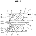
- a sealing device 1 shown in Fig. 2 is conventionally known as a high-pressure seal.
- This sealing device 1 is placed between two members 51 and 52 facing each other to seal so as to prevent sealing fluid on the high-pressure side H from leaking to the low-pressure side L, and is a combination of a seal ring 11, a relatively hard first back-up ring 21, and a relatively soft second back-up ring 31.
- the seal ring 11 is mounted in an annular mounting groove 53 provided on one of the two members 51 and 52, namely the member (for example, a shaft) 51, and is in close contact with the other member (for example, a housing) 52.
- the first back-up ring 21 is placed on the opposing sealing fluid side (the low-pressure side L) of the seal ring 11.
- the second back-up ring 31 is placed between the seal ring 11 and the first back-up ring 21.
- the mounting groove 53 is a groove with a rectangular cross-section because it is easy to process.
- the first back-up ring 21 is formed to have a triangular cross-section by having an end surface portion 21a that is a plane perpendicular to the axis, a peripheral surface portion 21b that is a cylindrical surface, and an inclined surface portion 21c.
- the end surface portion 21a is in contact with an opposing-sealing-fluid-side side surface portion 53b of the mounting groove 53; the peripheral surface portion 21b is in contact with the other member 52; and the inclined surface portion 21c intersects with the end surface portion 21a and the peripheral surface portion 21b.
- the second back-up ring 31 is formed to have a triangular cross-section by having an end surface portion 31a that is a plane perpendicular to the axis, a peripheral surface portion 31b that is a cylindrical surface, and an inclined surface portion 31c.
- the end surface portion 31a is in contact with the seal ring 11; the peripheral surface portion 31b is in contact with a bottom surface portion 53a of the mounting groove 53; and the inclined surface portion 31c is provided to correspond to the inclined surface portion 21c of the first back-up ring 21.
- the first back-up ring 21 is placed on the opposing sealing fluid side (the low-pressure side L) of the seal ring 11, and therefore, it is possible to prevent the seal ring 11 made of a rubbery elastic body from protruding into a gap 54 between the two members 51 and 52 and being damaged when subjected to high pressure P; furthermore, the second back-up ring 31 is placed between the seal ring 11 and the first back-up ring 21, and therefore, it is possible to prevent the seal ring 11 from protruding into a gap (not shown) between the first back-up ring 21 and the member 52 and being damaged.
- Patent Document 1 Japanese Unexamined Patent Publication No. 10-68467
- the cross-sectional shapes of the first and second back-up rings 21 and 31 are both a simple triangular shape, thus the following disadvantages are pointed out.
- the sealing device 1 when the above-described sealing device 1 is installed between the two members 51 and 52, as shown in Fig. 3A , first, the sealing device 1 is mounted in the mounting groove 53 of the member 51, and then, together with the member 51, the sealing device 1 is inserted in the inner peripheral side (a shaft hole 52a) of the member 52 (an arrow x).
- the outer diameter size d 1 of the seal ring 11 before insertion may be larger than the inner diameter size d 2 of the shaft hole 52a; in this case, the following event occurs.
- a corner 31d between the peripheral surface portion 31b and the inclined surface portion 31c of the second back-up ring 31 has an acute angle, and this acute corner 31d tends to be compressed in an axial direction when pressed against the side surface portion 53b of the mounting groove 53. Therefore, if the distance t between the side surface portion 53b of the mounting groove 53 and the seal ring 11 is reduced, the overall second back-up ring 31 moves to a direction of getting close to the side surface portion 53b of the mounting groove 53, and presses the first back-up ring 21.
- the outer periphery of the first back-up ring 21 interferes with the opening periphery 52b of the shaft hole 52a, which may damage the first back-up ring 21.
- the present invention is for a sealing device composed of a combination of a seal ring mounted in a mounting groove with a rectangular cross-section, a first back-up ring, and a second back-up ring, and an object of the invention is to provide a sealing device that can suppress the diameter expansion of the first back-up ring when inserted, thereby suppressing the damage on the first back-up ring.
- a sealing device is one that is placed between two members facing each other to seal in sealing fluid, and includes a seal ring that is mounted in a mounting groove provided on one of the two members and is in close contact with the other member; a relatively hard first back-up ring placed on the opposing sealing fluid side of the seal ring; and a relatively soft second back-up ring placed between the seal ring and the first back-up ring.
- the mounting groove is a groove with a rectangular cross-section.
- the first back-up ring has a shape having an end surface portion in contact with the opposing-sealing-fluid-side side surface portion of the mounting groove, a peripheral surface portion facing the other member, and an inclined surface portion intersecting with the end surface portion and the peripheral surface portion.
- the second back-up ring has a shape having an end surface portion in contact with the seal ring, a peripheral surface portion facing a bottom surface portion of the mounting groove, and an inclined surface portion that is provided to correspond to the inclined surface portion of the first back-up ring.
- a contact surface portion that is a plane perpendicular to the axis in contact with the opposing-sealing-fluid-side side surface portion of the mounting groove is provided in an inner peripheral end of the inclined surface portion of the second back-up ring.
- the inner diameter size of the first back-up ring is set to be larger than the outer diameter size of the contact surface portion of the second back-up ring.
- the outer diameter size of the first back-up ring is set to be smaller than the inner diameter size of the other member.
- the contact surface portion that is a plane perpendicular to the axis in contact with the opposing-sealing-fluid-side side surface portion of the mounting groove is provided in the inner peripheral end of the inclined surface portion of the second back-up ring; therefore, by bringing the contact surface portion that is a plane perpendicular to the axis into contact with the side surface portion of the mounting groove from the beginning of the mounting in the mounting groove, the overall second back-up ring does not move to a direction of getting close to the side surface portion of the mounting groove.
- the overall second back-up ring does not move to the direction of getting close to the side surface portion of the mounting groove; therefore, the second back-up ring does not press the first back-up ring, and the first back-up ring is not deformed as its outer diameter size is not expanded either. Accordingly, there never arises a situation in which the first back-up ring interferes with the opening periphery of the shaft hole when inserted; therefore, it is possible to suppress the damage on the first back-up ring caused by the interference.
- the first back-up ring and the second back-up ring can be both triangular in cross-section; however, in a case where the inclined surface portion of the first back-up ring is a surface with a concave circular cross-section, and the inclined surface portion of the second back-up ring is a surface with a convex circular cross-section, and the end surface portion of the second back-up ring is a surface with a concave circular cross-section, the following effects are exerted.
- the seal ring presses the end surface portion with a concave circular cross-section in the second back-up ring, thus the second back-up ring is elastically deformed, which causes its outer diameter size to be expanded, thereby pressing the first back-up ring.
- the pressed first back-up ring is also elastically deformed, which causes its outer diameter size to be expanded, and comes in contact with the other member, or reduces the radial distance to the other member. Accordingly, it is possible to expect the sealing effect of the first back-up ring elastically deformed outward in a radial direction in this way.
- the sealing device composed of a combination of the seal ring mounted in the mounting groove with a rectangular cross-section, the first back-up ring, and the second back-up ring, it is possible to suppress the diameter expansion of the first back-up ring when inserted, thereby suppressing the damage on the first back-up ring, and we can expect the sealing effect due to the first back-up ring.
- the present invention includes the following embodiments.
- Fig. 1 shows cross-sections of main parts of a sealing device 1 according to the embodiment of the present invention.
- the sealing device 1 according to the embodiment is one used in a high-pressure seal portion of hydraulic equipment such as a direct-injection injector, and is configured as below.
- the sealing device 1 is placed in an annular gap between two members facing each other, namely a shaft (one of the members) 51 and a housing (the other member) 52 to seal in sealing fluid existing on the high-pressure side H that is on the right of the drawing so that the sealing fluid does not leak to the low-pressure side (the atmosphere side) L that is on the left of the drawing.
- the sealing device 1 includes an O-ring 11 as a seal ring, a first back-up ring 21, and a second back-up ring 31.
- the O-ring 11 is mounted in an annular mounting groove 53 provided on the peripheral surface of the shaft 51, and is in close contact with the inner peripheral surface of a shaft hole of the housing 52.
- the first back-up ring 21 is placed on the opposing sealing fluid side (the low-pressure side L) of the O-ring 11, and is likewise mounted in the mounting groove 53.
- the second back-up ring 31 is placed between the O-ring 11 and the first back-up ring 21, and is likewise mounted in the mounting groove 53.
- a seal ring with another cross-sectional shape such as a D-ring or an X-ring, can be used.
- the O-ring 11 is made of a rubbery elastic body.
- the first back-up ring 21 is made of, for example, nylon resin harder than the second back-up ring 31.
- the second back-up ring 31 is made of, for example, PTFE resin softer than the first back-up ring 21.
- the mounting groove 53 is formed as a rectangular groove with a rectangular cross-section because it is easy to process. Therefore, a sort of tapered shape is not formed in the groove, and the mounting groove 53 is a combination of only a bottom surface portion 53a that is a cylindrical surface and both side surface portions 53b that are a plane perpendicular to the axis.
- the first back-up ring 21 has an end surface portion 21a that is a plane perpendicular to the axis on the opposing sealing fluid side (the low-pressure side L) thereof in contact with the side surface portion 53b of the mounting groove 53, a peripheral surface portion 21b that is a cylindrical surface on the outer peripheral side thereof in contact with the inner peripheral surface of the shaft hole of the housing 52, and an inclined surface portion 21c that is a tapered surface intersecting with the end surface portion 21a and the peripheral surface portion 21b, and is formed to be triangular (right triangular) or substantially triangular in cross-section.
- the diameter size (the inner diameter size) of the inclined surface portion 21c is tapered off from the sealing fluid side (the high-pressure side H) to the opposing sealing fluid side (the low-pressure side L).
- the second back-up ring 31 has an end surface portion 31a on the sealing fluid side (the high-pressure side H) thereof in contact with the seal ring 11, a peripheral surface portion 31b that is a cylindrical surface on the inner peripheral side thereof in contact with the bottom surface portion 53a of the mounting groove 53, and an inclined surface portion 31c that is a tapered surface intersecting with the end surface portion 31a and the peripheral surface portion 31b, and is formed to be triangular (right triangular) or substantially triangular in cross-section.
- the diameter size (the outer diameter size) of the inclined surface portion 31c is tapered off from the sealing fluid side (the high-pressure side H) to the opposing sealing fluid side (the low-pressure side L).
- a contact surface portion 31e that is a plane perpendicular to the axis in contact with the side surface portion 53b of the mounting groove 53 is provided in an inner peripheral end of the inclined surface portion 31c of the second back-up ring 31, and the inner diameter size d 3 of the first back-up ring 21 is set to be larger than the outer diameter size d 4 of the contact surface portion 31e.
- the contact surface portion 31e of the second back-up ring 31 and the end surface portion 21a of the first back-up ring 21 enable the both back-up rings 21 and 31 to be in contact with the side surface portion 53b of the mounting groove 53 at the same time.
- the outer diameter size d 5 of the first back-up ring 21 is set to be smaller than the inner diameter size d 6 of the housing 52 so that the first back-up ring 21 does not interfere with an opening periphery (not shown) of the shaft hole of the housing 52 when inserted.
- the inclined surface portion 21c of the first back-up ring 21 and the inclined surface portion 31c of the second back-up ring 31 are provided to correspond to each other; the inclined surface portion 21c of the first back-up ring 21 is a surface with a concave circular cross-section, and the inclined surface portion 31c of the second back-up ring 31 is a surface with a convex circular cross-section. Furthermore, the end surface portion 31a of the second back-up ring 31 is also a surface with a concave circular cross-section.
- the first back-up ring 21 is placed on the opposing sealing fluid side (the low-pressure side L) of the seal ring 11, and therefore, it is possible to prevent the seal ring 11 from protruding into a gap 54 between the shaft 51 and the housing 52 and being damaged when subjected to high pressure P; furthermore, the second back-up ring 31 is placed between the seal ring 11 and the first back-up ring 21, and therefore, it is possible to prevent the seal ring 11 from protruding into a gap 55 between the first back-up ring 21 and the housing 52 and being damaged. Accordingly, it is possible to suppress the degradation of sealing performance caused by the seal ring 11 protruding into the gap 54 or 55 and being damaged.
- the contact surface portion 31e that is a plane perpendicular to the axis in contact with the opposing-sealing-fluid-side side surface portion 53b of the mounting groove 53 is provided in the inner peripheral end of the inclined surface portion 31c of the second back-up ring 31; therefore, by bringing the contact surface portion 31e that is a plane perpendicular to the axis into contact with the side surface portion 53b of the mounting groove 53 from the beginning of the mounting in the mounting groove 53, the overall second back-up ring 31 does not move to a direction of getting close to the side surface portion 53b of the mounting groove 53.
- the sealing device 1 when the sealing device 1 is inserted into a shaft hole 52a of the housing 52, the overall second back-up ring 31 does not move to the direction of getting close to the side surface portion 53b of the mounting groove 53, thus the second back-up ring 31 does not press the first back-up ring 21, which prevents the first back-up ring 21 from deformation of its outer diameter size d 5 being expanded. Accordingly, there never arises a situation in which the first back-up ring 21 interferes with the opening periphery of the shaft hole 52a when inserted; therefore, it is possible to suppress the damage on the first back-up ring 21 caused by the interference.
- the inclined surface portion 21c of the first back-up ring 21 is a surface with a concave circular cross-section
- the inclined surface portion 31c of the second back-up ring 31 is a surface with a convex circular cross-section
- the end surface portion 31a of the second back-up ring 31 is a surface with a concave circular cross-section; therefore, if high pressure P acts on the seal ring 11, the seal ring 11 presses the end surface portion 31a with a concave circular cross-section in the second back-up ring 31, and the second back-up ring 31 is elastically deformed, which causes its outer diameter size to be expanded, thereby pressing the first back-up ring 21.
- the pressed first back-up ring 21 is also elastically deformed, which causes its outer diameter size d 5 to be expanded, and, as a result, comes in contact with the inner surface of the housing 52, or at least reduces the radial distance to the inner surface of the housing 52. Accordingly, the first back-up ring 21 elastically deformed outward in a radial direction in this way exerts the sealing function, and therefore, it is possible to expect the sealing effect of the first back-up ring 21, and is possible to enhance the sealing performance of the sealing device 1.
Landscapes
- Engineering & Computer Science (AREA)
- General Engineering & Computer Science (AREA)
- Mechanical Engineering (AREA)
- Physics & Mathematics (AREA)
- Architecture (AREA)
- Fluid Mechanics (AREA)
- Gasket Seals (AREA)
- Sealing Devices (AREA)
Applications Claiming Priority (2)
| Application Number | Priority Date | Filing Date | Title |
|---|---|---|---|
| JP2015243761 | 2015-12-15 | ||
| PCT/JP2016/082211 WO2017104278A1 (ja) | 2015-12-15 | 2016-10-31 | 密封装置 |
Publications (3)
| Publication Number | Publication Date |
|---|---|
| EP3392533A1 true EP3392533A1 (de) | 2018-10-24 |
| EP3392533A4 EP3392533A4 (de) | 2018-12-19 |
| EP3392533B1 EP3392533B1 (de) | 2020-05-06 |
Family
ID=59056019
Family Applications (1)
| Application Number | Title | Priority Date | Filing Date |
|---|---|---|---|
| EP16875263.2A Active EP3392533B1 (de) | 2015-12-15 | 2016-10-31 | Dichtungsvorrichtung |
Country Status (5)
| Country | Link |
|---|---|
| US (1) | US11187325B2 (de) |
| EP (1) | EP3392533B1 (de) |
| JP (1) | JP6147946B1 (de) |
| CN (1) | CN108291650B (de) |
| WO (1) | WO2017104278A1 (de) |
Cited By (3)
| Publication number | Priority date | Publication date | Assignee | Title |
|---|---|---|---|---|
| US11174825B2 (en) | 2019-02-11 | 2021-11-16 | Caterpillar Inc. | Seal configuration for fuel injector |
| WO2021228523A1 (de) * | 2020-05-12 | 2021-11-18 | Uhde High Pressure Technologies Gmbh | Hochdruckdichtungsanordnung und hochdruckanlage zur radialen abdichtung eines behälterverschlusses eines hochdruckbehälters sowie deren verwendung |
| BE1028293B1 (de) * | 2020-05-12 | 2021-12-16 | Thyssenkrupp Ag | Hochdruckdichtungsanordnung und Hochdruckanlage zur radialen Abdichtung eines Behälterverschlusses eines Hochdruckbehälters sowie deren Verwendung |
Families Citing this family (9)
| Publication number | Priority date | Publication date | Assignee | Title |
|---|---|---|---|---|
| JP6809917B2 (ja) * | 2017-01-31 | 2021-01-06 | 株式会社バルカー | 複合シール材 |
| JP6807891B2 (ja) | 2018-04-16 | 2021-01-06 | 豊田合成株式会社 | 高圧タンクのシール構造 |
| CN109268501A (zh) * | 2018-10-29 | 2019-01-25 | 西安航天发动机有限公司 | 一种可径向补偿的径向密封结构 |
| JP7243978B2 (ja) * | 2019-01-23 | 2023-03-22 | 株式会社荒井製作所 | 密封装置 |
| US11761540B2 (en) | 2020-08-19 | 2023-09-19 | Saint-Gobain Performance Plastics Corporation | Seal stack assembly |
| CN116137883A (zh) | 2020-08-21 | 2023-05-19 | 美国圣戈班性能塑料公司 | 用于密封堆叠组件的自动擦拭器 |
| KR20220076798A (ko) * | 2020-12-01 | 2022-06-08 | 현대자동차주식회사 | 가변형 백업링 및 이를 포함한 실링구조 |
| CN115025716B (zh) * | 2022-07-14 | 2025-12-26 | 温岭市泽国化工机械有限公司 | 成型辊及其密封结构 |
| KR20250049095A (ko) * | 2023-10-04 | 2025-04-11 | 삼성전자주식회사 | 씰링 링 어셈블리, 이를 포함하는 기판 처리 장치 및 이를 이용한 반도체 소자의 제조 방법 |
Family Cites Families (18)
| Publication number | Priority date | Publication date | Assignee | Title |
|---|---|---|---|---|
| US3394941A (en) * | 1965-10-21 | 1968-07-30 | Shamban & Co W S | Sealing ring assembly |
| JPS4631623Y1 (de) * | 1967-12-26 | 1971-11-01 | ||
| US3854735A (en) * | 1972-10-24 | 1974-12-17 | Exxon Production Research Co | Static face seal |
| JPS562052Y2 (de) * | 1974-11-27 | 1981-01-17 | ||
| US4387902A (en) * | 1981-10-19 | 1983-06-14 | C. E. Conover & Co., Inc. | Elastomeric seal ring with self-lubricating wear-reducing feature |
| US4489953A (en) * | 1981-12-10 | 1984-12-25 | Fmc Corporation | Fire-safe seal for swivel joint |
| JP3532714B2 (ja) | 1996-06-21 | 2004-05-31 | Nok株式会社 | シール装置 |
| US6736407B2 (en) | 2001-12-27 | 2004-05-18 | Flow International Corporation | Static fluid seals and seal assemblies for ultrahigh pressure fluid containment |
| JP2007146946A (ja) * | 2005-11-25 | 2007-06-14 | Toyota Motor Corp | 高圧タンク |
| JP5257606B2 (ja) * | 2009-02-18 | 2013-08-07 | Nok株式会社 | 密封装置 |
| US9109703B2 (en) | 2010-02-11 | 2015-08-18 | Kalsi Engineering, Inc. | Hydrodynamic backup ring |
| JP2012154387A (ja) * | 2011-01-25 | 2012-08-16 | Nippon Valqua Ind Ltd | シール材 |
| CN202520948U (zh) * | 2011-10-19 | 2012-11-07 | 三一重机有限公司 | 一种液压油缸的密封结构 |
| DE102012001004A1 (de) * | 2012-01-20 | 2013-07-25 | Uhde High Pressure Technologies Gmbh | Stützringanordnung für eine Hochdruckdichtung |
| CN203162150U (zh) * | 2013-04-17 | 2013-08-28 | 湖北佳恒科技有限公司 | 一种改进导向套密封性的液压油缸 |
| US10801622B2 (en) * | 2013-04-18 | 2020-10-13 | Bal Seal Engineering, Llc | Interlocking face seal assemblies and related methods |
| EP3115657B1 (de) * | 2014-03-06 | 2019-09-25 | NOK Corporation | Dichtungsvorrichtung |
| US10107401B2 (en) * | 2014-09-24 | 2018-10-23 | Nok Corporation | Sealing structure |
-
2016
- 2016-10-31 JP JP2017509061A patent/JP6147946B1/ja active Active
- 2016-10-31 WO PCT/JP2016/082211 patent/WO2017104278A1/ja not_active Ceased
- 2016-10-31 CN CN201680067679.3A patent/CN108291650B/zh active Active
- 2016-10-31 EP EP16875263.2A patent/EP3392533B1/de active Active
- 2016-10-31 US US16/061,978 patent/US11187325B2/en not_active Expired - Fee Related
Cited By (3)
| Publication number | Priority date | Publication date | Assignee | Title |
|---|---|---|---|---|
| US11174825B2 (en) | 2019-02-11 | 2021-11-16 | Caterpillar Inc. | Seal configuration for fuel injector |
| WO2021228523A1 (de) * | 2020-05-12 | 2021-11-18 | Uhde High Pressure Technologies Gmbh | Hochdruckdichtungsanordnung und hochdruckanlage zur radialen abdichtung eines behälterverschlusses eines hochdruckbehälters sowie deren verwendung |
| BE1028293B1 (de) * | 2020-05-12 | 2021-12-16 | Thyssenkrupp Ag | Hochdruckdichtungsanordnung und Hochdruckanlage zur radialen Abdichtung eines Behälterverschlusses eines Hochdruckbehälters sowie deren Verwendung |
Also Published As
| Publication number | Publication date |
|---|---|
| CN108291650B (zh) | 2020-06-30 |
| WO2017104278A1 (ja) | 2017-06-22 |
| CN108291650A (zh) | 2018-07-17 |
| JPWO2017104278A1 (ja) | 2017-12-21 |
| US20180372223A1 (en) | 2018-12-27 |
| US11187325B2 (en) | 2021-11-30 |
| JP6147946B1 (ja) | 2017-06-14 |
| EP3392533B1 (de) | 2020-05-06 |
| EP3392533A4 (de) | 2018-12-19 |
Similar Documents
| Publication | Publication Date | Title |
|---|---|---|
| EP3392533B1 (de) | Dichtungsvorrichtung | |
| US20170089465A1 (en) | Gasket | |
| KR20150027110A (ko) | 시일재 및 압륜 및 커플링 및 밸브 | |
| JP2017180472A (ja) | 管継手および管の接合方法 | |
| WO2015133595A1 (ja) | 密封装置 | |
| US20160186864A1 (en) | Sealing ring | |
| EP1950472B1 (de) | Dichtungsvorrichtung | |
| JP2007071329A (ja) | バックアップリング | |
| EP1950473B1 (de) | Eingeschlossene vorrichtung zur kohlendioxidgasversiegelung | |
| JP4853633B2 (ja) | 密封装置 | |
| JP7285627B2 (ja) | ワッシャー固定方法およびシステム | |
| JP6442647B1 (ja) | 密封装置 | |
| JP2009024712A (ja) | 密封装置 | |
| JP4496004B2 (ja) | 管継手 | |
| JP4892619B2 (ja) | 管継手 | |
| JP2010014202A (ja) | 密封装置 | |
| JP6570931B2 (ja) | 密封装置 | |
| JP2020176633A (ja) | 密封装置 | |
| KR20070056665A (ko) | 변속기의 스프링 리테이너 결합구조 |
Legal Events
| Date | Code | Title | Description |
|---|---|---|---|
| STAA | Information on the status of an ep patent application or granted ep patent |
Free format text: STATUS: THE INTERNATIONAL PUBLICATION HAS BEEN MADE |
|
| PUAI | Public reference made under article 153(3) epc to a published international application that has entered the european phase |
Free format text: ORIGINAL CODE: 0009012 |
|
| STAA | Information on the status of an ep patent application or granted ep patent |
Free format text: STATUS: REQUEST FOR EXAMINATION WAS MADE |
|
| 17P | Request for examination filed |
Effective date: 20180619 |
|
| AK | Designated contracting states |
Kind code of ref document: A1 Designated state(s): AL AT BE BG CH CY CZ DE DK EE ES FI FR GB GR HR HU IE IS IT LI LT LU LV MC MK MT NL NO PL PT RO RS SE SI SK SM TR |
|
| AX | Request for extension of the european patent |
Extension state: BA ME |
|
| A4 | Supplementary search report drawn up and despatched |
Effective date: 20181115 |
|
| RIC1 | Information provided on ipc code assigned before grant |
Ipc: F16J 15/16 20060101ALI20181109BHEP Ipc: F16J 15/10 20060101ALI20181109BHEP Ipc: F16J 15/48 20060101ALI20181109BHEP Ipc: F16J 15/46 20060101AFI20181109BHEP |
|
| DAV | Request for validation of the european patent (deleted) | ||
| DAX | Request for extension of the european patent (deleted) | ||
| GRAP | Despatch of communication of intention to grant a patent |
Free format text: ORIGINAL CODE: EPIDOSNIGR1 |
|
| STAA | Information on the status of an ep patent application or granted ep patent |
Free format text: STATUS: GRANT OF PATENT IS INTENDED |
|
| INTG | Intention to grant announced |
Effective date: 20191121 |
|
| GRAS | Grant fee paid |
Free format text: ORIGINAL CODE: EPIDOSNIGR3 |
|
| GRAA | (expected) grant |
Free format text: ORIGINAL CODE: 0009210 |
|
| STAA | Information on the status of an ep patent application or granted ep patent |
Free format text: STATUS: THE PATENT HAS BEEN GRANTED |
|
| AK | Designated contracting states |
Kind code of ref document: B1 Designated state(s): AL AT BE BG CH CY CZ DE DK EE ES FI FR GB GR HR HU IE IS IT LI LT LU LV MC MK MT NL NO PL PT RO RS SE SI SK SM TR |
|
| REG | Reference to a national code |
Ref country code: GB Ref legal event code: FG4D |
|
| REG | Reference to a national code |
Ref country code: CH Ref legal event code: EP Ref country code: AT Ref legal event code: REF Ref document number: 1267278 Country of ref document: AT Kind code of ref document: T Effective date: 20200515 |
|
| REG | Reference to a national code |
Ref country code: DE Ref legal event code: R096 Ref document number: 602016036189 Country of ref document: DE |
|
| REG | Reference to a national code |
Ref country code: IE Ref legal event code: FG4D |
|
| REG | Reference to a national code |
Ref country code: LT Ref legal event code: MG4D |
|
| REG | Reference to a national code |
Ref country code: NL Ref legal event code: MP Effective date: 20200506 |
|
| PG25 | Lapsed in a contracting state [announced via postgrant information from national office to epo] |
Ref country code: SE Free format text: LAPSE BECAUSE OF FAILURE TO SUBMIT A TRANSLATION OF THE DESCRIPTION OR TO PAY THE FEE WITHIN THE PRESCRIBED TIME-LIMIT Effective date: 20200506 Ref country code: PT Free format text: LAPSE BECAUSE OF FAILURE TO SUBMIT A TRANSLATION OF THE DESCRIPTION OR TO PAY THE FEE WITHIN THE PRESCRIBED TIME-LIMIT Effective date: 20200907 Ref country code: IS Free format text: LAPSE BECAUSE OF FAILURE TO SUBMIT A TRANSLATION OF THE DESCRIPTION OR TO PAY THE FEE WITHIN THE PRESCRIBED TIME-LIMIT Effective date: 20200906 Ref country code: FI Free format text: LAPSE BECAUSE OF FAILURE TO SUBMIT A TRANSLATION OF THE DESCRIPTION OR TO PAY THE FEE WITHIN THE PRESCRIBED TIME-LIMIT Effective date: 20200506 Ref country code: NO Free format text: LAPSE BECAUSE OF FAILURE TO SUBMIT A TRANSLATION OF THE DESCRIPTION OR TO PAY THE FEE WITHIN THE PRESCRIBED TIME-LIMIT Effective date: 20200806 Ref country code: GR Free format text: LAPSE BECAUSE OF FAILURE TO SUBMIT A TRANSLATION OF THE DESCRIPTION OR TO PAY THE FEE WITHIN THE PRESCRIBED TIME-LIMIT Effective date: 20200807 Ref country code: LT Free format text: LAPSE BECAUSE OF FAILURE TO SUBMIT A TRANSLATION OF THE DESCRIPTION OR TO PAY THE FEE WITHIN THE PRESCRIBED TIME-LIMIT Effective date: 20200506 |
|
| PG25 | Lapsed in a contracting state [announced via postgrant information from national office to epo] |
Ref country code: LV Free format text: LAPSE BECAUSE OF FAILURE TO SUBMIT A TRANSLATION OF THE DESCRIPTION OR TO PAY THE FEE WITHIN THE PRESCRIBED TIME-LIMIT Effective date: 20200506 Ref country code: BG Free format text: LAPSE BECAUSE OF FAILURE TO SUBMIT A TRANSLATION OF THE DESCRIPTION OR TO PAY THE FEE WITHIN THE PRESCRIBED TIME-LIMIT Effective date: 20200806 Ref country code: RS Free format text: LAPSE BECAUSE OF FAILURE TO SUBMIT A TRANSLATION OF THE DESCRIPTION OR TO PAY THE FEE WITHIN THE PRESCRIBED TIME-LIMIT Effective date: 20200506 Ref country code: HR Free format text: LAPSE BECAUSE OF FAILURE TO SUBMIT A TRANSLATION OF THE DESCRIPTION OR TO PAY THE FEE WITHIN THE PRESCRIBED TIME-LIMIT Effective date: 20200506 |
|
| REG | Reference to a national code |
Ref country code: AT Ref legal event code: MK05 Ref document number: 1267278 Country of ref document: AT Kind code of ref document: T Effective date: 20200506 |
|
| PG25 | Lapsed in a contracting state [announced via postgrant information from national office to epo] |
Ref country code: NL Free format text: LAPSE BECAUSE OF FAILURE TO SUBMIT A TRANSLATION OF THE DESCRIPTION OR TO PAY THE FEE WITHIN THE PRESCRIBED TIME-LIMIT Effective date: 20200506 Ref country code: AL Free format text: LAPSE BECAUSE OF FAILURE TO SUBMIT A TRANSLATION OF THE DESCRIPTION OR TO PAY THE FEE WITHIN THE PRESCRIBED TIME-LIMIT Effective date: 20200506 |
|
| PG25 | Lapsed in a contracting state [announced via postgrant information from national office to epo] |
Ref country code: RO Free format text: LAPSE BECAUSE OF FAILURE TO SUBMIT A TRANSLATION OF THE DESCRIPTION OR TO PAY THE FEE WITHIN THE PRESCRIBED TIME-LIMIT Effective date: 20200506 Ref country code: EE Free format text: LAPSE BECAUSE OF FAILURE TO SUBMIT A TRANSLATION OF THE DESCRIPTION OR TO PAY THE FEE WITHIN THE PRESCRIBED TIME-LIMIT Effective date: 20200506 Ref country code: AT Free format text: LAPSE BECAUSE OF FAILURE TO SUBMIT A TRANSLATION OF THE DESCRIPTION OR TO PAY THE FEE WITHIN THE PRESCRIBED TIME-LIMIT Effective date: 20200506 Ref country code: SM Free format text: LAPSE BECAUSE OF FAILURE TO SUBMIT A TRANSLATION OF THE DESCRIPTION OR TO PAY THE FEE WITHIN THE PRESCRIBED TIME-LIMIT Effective date: 20200506 Ref country code: IT Free format text: LAPSE BECAUSE OF FAILURE TO SUBMIT A TRANSLATION OF THE DESCRIPTION OR TO PAY THE FEE WITHIN THE PRESCRIBED TIME-LIMIT Effective date: 20200506 Ref country code: DK Free format text: LAPSE BECAUSE OF FAILURE TO SUBMIT A TRANSLATION OF THE DESCRIPTION OR TO PAY THE FEE WITHIN THE PRESCRIBED TIME-LIMIT Effective date: 20200506 Ref country code: ES Free format text: LAPSE BECAUSE OF FAILURE TO SUBMIT A TRANSLATION OF THE DESCRIPTION OR TO PAY THE FEE WITHIN THE PRESCRIBED TIME-LIMIT Effective date: 20200506 Ref country code: CZ Free format text: LAPSE BECAUSE OF FAILURE TO SUBMIT A TRANSLATION OF THE DESCRIPTION OR TO PAY THE FEE WITHIN THE PRESCRIBED TIME-LIMIT Effective date: 20200506 |
|
| REG | Reference to a national code |
Ref country code: DE Ref legal event code: R097 Ref document number: 602016036189 Country of ref document: DE |
|
| PG25 | Lapsed in a contracting state [announced via postgrant information from national office to epo] |
Ref country code: SK Free format text: LAPSE BECAUSE OF FAILURE TO SUBMIT A TRANSLATION OF THE DESCRIPTION OR TO PAY THE FEE WITHIN THE PRESCRIBED TIME-LIMIT Effective date: 20200506 Ref country code: PL Free format text: LAPSE BECAUSE OF FAILURE TO SUBMIT A TRANSLATION OF THE DESCRIPTION OR TO PAY THE FEE WITHIN THE PRESCRIBED TIME-LIMIT Effective date: 20200506 |
|
| PLBE | No opposition filed within time limit |
Free format text: ORIGINAL CODE: 0009261 |
|
| STAA | Information on the status of an ep patent application or granted ep patent |
Free format text: STATUS: NO OPPOSITION FILED WITHIN TIME LIMIT |
|
| 26N | No opposition filed |
Effective date: 20210209 |
|
| PG25 | Lapsed in a contracting state [announced via postgrant information from national office to epo] |
Ref country code: SI Free format text: LAPSE BECAUSE OF FAILURE TO SUBMIT A TRANSLATION OF THE DESCRIPTION OR TO PAY THE FEE WITHIN THE PRESCRIBED TIME-LIMIT Effective date: 20200506 |
|
| REG | Reference to a national code |
Ref country code: CH Ref legal event code: PL |
|
| PG25 | Lapsed in a contracting state [announced via postgrant information from national office to epo] |
Ref country code: LU Free format text: LAPSE BECAUSE OF NON-PAYMENT OF DUE FEES Effective date: 20201031 Ref country code: MC Free format text: LAPSE BECAUSE OF FAILURE TO SUBMIT A TRANSLATION OF THE DESCRIPTION OR TO PAY THE FEE WITHIN THE PRESCRIBED TIME-LIMIT Effective date: 20200506 |
|
| REG | Reference to a national code |
Ref country code: BE Ref legal event code: MM Effective date: 20201031 |
|
| PG25 | Lapsed in a contracting state [announced via postgrant information from national office to epo] |
Ref country code: LI Free format text: LAPSE BECAUSE OF NON-PAYMENT OF DUE FEES Effective date: 20201031 Ref country code: BE Free format text: LAPSE BECAUSE OF NON-PAYMENT OF DUE FEES Effective date: 20201031 Ref country code: CH Free format text: LAPSE BECAUSE OF NON-PAYMENT OF DUE FEES Effective date: 20201031 |
|
| PG25 | Lapsed in a contracting state [announced via postgrant information from national office to epo] |
Ref country code: IE Free format text: LAPSE BECAUSE OF NON-PAYMENT OF DUE FEES Effective date: 20201031 |
|
| PGFP | Annual fee paid to national office [announced via postgrant information from national office to epo] |
Ref country code: FR Payment date: 20210913 Year of fee payment: 6 |
|
| PGFP | Annual fee paid to national office [announced via postgrant information from national office to epo] |
Ref country code: GB Payment date: 20210922 Year of fee payment: 6 |
|
| PGFP | Annual fee paid to national office [announced via postgrant information from national office to epo] |
Ref country code: DE Payment date: 20210923 Year of fee payment: 6 |
|
| PG25 | Lapsed in a contracting state [announced via postgrant information from national office to epo] |
Ref country code: TR Free format text: LAPSE BECAUSE OF FAILURE TO SUBMIT A TRANSLATION OF THE DESCRIPTION OR TO PAY THE FEE WITHIN THE PRESCRIBED TIME-LIMIT Effective date: 20200506 Ref country code: MT Free format text: LAPSE BECAUSE OF FAILURE TO SUBMIT A TRANSLATION OF THE DESCRIPTION OR TO PAY THE FEE WITHIN THE PRESCRIBED TIME-LIMIT Effective date: 20200506 Ref country code: CY Free format text: LAPSE BECAUSE OF FAILURE TO SUBMIT A TRANSLATION OF THE DESCRIPTION OR TO PAY THE FEE WITHIN THE PRESCRIBED TIME-LIMIT Effective date: 20200506 |
|
| PG25 | Lapsed in a contracting state [announced via postgrant information from national office to epo] |
Ref country code: MK Free format text: LAPSE BECAUSE OF FAILURE TO SUBMIT A TRANSLATION OF THE DESCRIPTION OR TO PAY THE FEE WITHIN THE PRESCRIBED TIME-LIMIT Effective date: 20200506 |
|
| REG | Reference to a national code |
Ref country code: DE Ref legal event code: R119 Ref document number: 602016036189 Country of ref document: DE |
|
| GBPC | Gb: european patent ceased through non-payment of renewal fee |
Effective date: 20221031 |
|
| PG25 | Lapsed in a contracting state [announced via postgrant information from national office to epo] |
Ref country code: FR Free format text: LAPSE BECAUSE OF NON-PAYMENT OF DUE FEES Effective date: 20221031 Ref country code: DE Free format text: LAPSE BECAUSE OF NON-PAYMENT OF DUE FEES Effective date: 20230503 |
|
| PG25 | Lapsed in a contracting state [announced via postgrant information from national office to epo] |
Ref country code: GB Free format text: LAPSE BECAUSE OF NON-PAYMENT OF DUE FEES Effective date: 20221031 |