EP3392609B1 - Optische detektionsvorrichtung zur detektion eines fehlers des freiheitsgrades einer spindel und detektionsverfahren dafür - Google Patents
Optische detektionsvorrichtung zur detektion eines fehlers des freiheitsgrades einer spindel und detektionsverfahren dafür Download PDFInfo
- Publication number
- EP3392609B1 EP3392609B1 EP17180396.8A EP17180396A EP3392609B1 EP 3392609 B1 EP3392609 B1 EP 3392609B1 EP 17180396 A EP17180396 A EP 17180396A EP 3392609 B1 EP3392609 B1 EP 3392609B1
- Authority
- EP
- European Patent Office
- Prior art keywords
- sensor
- axis
- deposited
- laser head
- displacement sensor
- Prior art date
- Legal status (The legal status is an assumption and is not a legal conclusion. Google has not performed a legal analysis and makes no representation as to the accuracy of the status listed.)
- Active
Links
Images





Classifications
-
- G—PHYSICS
- G01—MEASURING; TESTING
- G01B—MEASURING LENGTH, THICKNESS OR SIMILAR LINEAR DIMENSIONS; MEASURING ANGLES; MEASURING AREAS; MEASURING IRREGULARITIES OF SURFACES OR CONTOURS
- G01B11/00—Measuring arrangements characterised by the use of optical techniques
- G01B11/02—Measuring arrangements characterised by the use of optical techniques for measuring length, width or thickness
- G01B11/026—Measuring arrangements characterised by the use of optical techniques for measuring length, width or thickness by measuring distance between sensor and object
-
- G—PHYSICS
- G01—MEASURING; TESTING
- G01B—MEASURING LENGTH, THICKNESS OR SIMILAR LINEAR DIMENSIONS; MEASURING ANGLES; MEASURING AREAS; MEASURING IRREGULARITIES OF SURFACES OR CONTOURS
- G01B11/00—Measuring arrangements characterised by the use of optical techniques
- G01B11/26—Measuring arrangements characterised by the use of optical techniques for measuring angles or tapers; for testing the alignment of axes
-
- G—PHYSICS
- G01—MEASURING; TESTING
- G01M—TESTING STATIC OR DYNAMIC BALANCE OF MACHINES OR STRUCTURES; TESTING OF STRUCTURES OR APPARATUS, NOT OTHERWISE PROVIDED FOR
- G01M11/00—Testing of optical apparatus; Testing structures by optical methods not otherwise provided for
- G01M11/08—Testing mechanical properties
-
- B—PERFORMING OPERATIONS; TRANSPORTING
- B23—MACHINE TOOLS; METAL-WORKING NOT OTHERWISE PROVIDED FOR
- B23B—TURNING; BORING
- B23B23/00—Tailstocks; Centres
- B23B23/04—Live centres
-
- B—PERFORMING OPERATIONS; TRANSPORTING
- B23—MACHINE TOOLS; METAL-WORKING NOT OTHERWISE PROVIDED FOR
- B23Q—DETAILS, COMPONENTS, OR ACCESSORIES FOR MACHINE TOOLS, e.g. ARRANGEMENTS FOR COPYING OR CONTROLLING; MACHINE TOOLS IN GENERAL CHARACTERISED BY THE CONSTRUCTION OF PARTICULAR DETAILS OR COMPONENTS; COMBINATIONS OR ASSOCIATIONS OF METAL-WORKING MACHINES, NOT DIRECTED TO A PARTICULAR RESULT
- B23Q17/00—Arrangements for observing, indicating or measuring on machine tools
- B23Q17/22—Arrangements for observing, indicating or measuring on machine tools for indicating or measuring existing or desired position of tool or work
- B23Q17/2233—Arrangements for observing, indicating or measuring on machine tools for indicating or measuring existing or desired position of tool or work for adjusting the tool relative to the workpiece
-
- B—PERFORMING OPERATIONS; TRANSPORTING
- B23—MACHINE TOOLS; METAL-WORKING NOT OTHERWISE PROVIDED FOR
- B23Q—DETAILS, COMPONENTS, OR ACCESSORIES FOR MACHINE TOOLS, e.g. ARRANGEMENTS FOR COPYING OR CONTROLLING; MACHINE TOOLS IN GENERAL CHARACTERISED BY THE CONSTRUCTION OF PARTICULAR DETAILS OR COMPONENTS; COMBINATIONS OR ASSOCIATIONS OF METAL-WORKING MACHINES, NOT DIRECTED TO A PARTICULAR RESULT
- B23Q17/00—Arrangements for observing, indicating or measuring on machine tools
- B23Q17/24—Arrangements for observing, indicating or measuring on machine tools using optics or electromagnetic waves
-
- G—PHYSICS
- G01—MEASURING; TESTING
- G01B—MEASURING LENGTH, THICKNESS OR SIMILAR LINEAR DIMENSIONS; MEASURING ANGLES; MEASURING AREAS; MEASURING IRREGULARITIES OF SURFACES OR CONTOURS
- G01B11/00—Measuring arrangements characterised by the use of optical techniques
- G01B11/26—Measuring arrangements characterised by the use of optical techniques for measuring angles or tapers; for testing the alignment of axes
- G01B11/27—Measuring arrangements characterised by the use of optical techniques for measuring angles or tapers; for testing the alignment of axes for testing the alignment of axes
-
- G—PHYSICS
- G01—MEASURING; TESTING
- G01B—MEASURING LENGTH, THICKNESS OR SIMILAR LINEAR DIMENSIONS; MEASURING ANGLES; MEASURING AREAS; MEASURING IRREGULARITIES OF SURFACES OR CONTOURS
- G01B21/00—Measuring arrangements or details thereof, where the measuring technique is not covered by the other groups of this subclass, unspecified or not relevant
- G01B21/02—Measuring arrangements or details thereof, where the measuring technique is not covered by the other groups of this subclass, unspecified or not relevant for measuring length, width, or thickness
- G01B21/04—Measuring arrangements or details thereof, where the measuring technique is not covered by the other groups of this subclass, unspecified or not relevant for measuring length, width, or thickness by measuring coordinates of points
- G01B21/042—Calibration or calibration artifacts
-
- B—PERFORMING OPERATIONS; TRANSPORTING
- B23—MACHINE TOOLS; METAL-WORKING NOT OTHERWISE PROVIDED FOR
- B23Q—DETAILS, COMPONENTS, OR ACCESSORIES FOR MACHINE TOOLS, e.g. ARRANGEMENTS FOR COPYING OR CONTROLLING; MACHINE TOOLS IN GENERAL CHARACTERISED BY THE CONSTRUCTION OF PARTICULAR DETAILS OR COMPONENTS; COMBINATIONS OR ASSOCIATIONS OF METAL-WORKING MACHINES, NOT DIRECTED TO A PARTICULAR RESULT
- B23Q17/00—Arrangements for observing, indicating or measuring on machine tools
- B23Q2017/001—Measurement or correction of run-out or eccentricity
-
- H—ELECTRICITY
- H01—ELECTRIC ELEMENTS
- H01S—DEVICES USING THE PROCESS OF LIGHT AMPLIFICATION BY STIMULATED EMISSION OF RADIATION [LASER] TO AMPLIFY OR GENERATE LIGHT; DEVICES USING STIMULATED EMISSION OF ELECTROMAGNETIC RADIATION IN WAVE RANGES OTHER THAN OPTICAL
- H01S3/00—Lasers, i.e. devices using stimulated emission of electromagnetic radiation in the infrared, visible or ultraviolet wave range
Definitions
- the present invention relates to an optical detecting apparatus for detecting a degree of freedom error of a spindle and a detecting method thereof, and more particularly to an optical detecting apparatus that may reduce the cost of assembly and use and to a detecting method that may be used to detect the precision detection of different kinds of powered machinery.
- a conventional powered machinery has a spindle and a rotating platform, and the rotating platform has a rotation axis.
- An error source A between the spindle and the rotation axis of the rotating platform can be divided into six parts, the spindle has three position errors ( ⁇ x ( ⁇ ), ⁇ y ( ⁇ ), ⁇ z ( ⁇ )) and an angle deflection error (wobble , ⁇ ).
- a radial error of the spindle is detected by the positions errors of ⁇ x ( ⁇ ), ⁇ x ( ⁇ ), and an axial error of the spindle is detected by the other position error of ⁇ z ( ⁇ ).
- the rotation axis of the rotating platform has tree angle positioning errors ( ⁇ x ( ⁇ ), ⁇ y ( ⁇ ), ⁇ z ( ⁇ )) of X axis, Y axis, and Z axis.
- the static detecting method is detected by using a standard bar and a dial indicator.
- a rotation error of the spindle is detected by the value of the dial indicator.
- the static detecting method has a major shortcoming of the measurement without carried out under the actual speed and the error includes the assembly error of the standard bar. Then, the static detecting method cannot detect the real rotation accuracy of the spindle.
- the dynamic detecting method may overcome the above-mentioned shortcoming of the static detecting method, and may use a high speed rotational spindle dynamic deflection measuring instrument (LION TARGA III PCB) to detect the conventional powered machinery.
- the above-mentioned measuring instrument has five non-contact capacitive sensors to detect the rotation error, the angle deflection error, the radial error, and the axial error of the spindle under the actual speed.
- the price of the non-contact capacitive sensors is quite expensive, so it is not easy to buy.
- the conventional powered machinery When the conventional powered machinery is used to process the aerospace elements, since most of the aerospace elements are efficiently removed from solid blocks by a tool of the conventional powered machinery, and most of the processing time is very long.
- the internal and external heat sources will cause the structures or components of the conventional powered machinery thermal deformation, resulting in deviation of process positioning accuracy. This may make the spindle generate eccentricity after rotating a period of time, and cause the spindle loss the processing accuracy by the axial and radial movement and the deflection error of the spindle.
- the error of the spindle must be resolved in order to improve the processing accuracy.
- the dynamic detecting method is used the expensive high speed rotational spindle dynamic deflection measuring instrument (LION TARGA III PCB) to detect the errors of the spindle under a dynamic condition.
- the cost of the LION TARGA III PCB is NT $ 1 to 2 million, and this will influence the procurement of the users and cannot enhance the accuracy of processing by analyzing the errors of the spindle of the conventional powered machinery under the high-speed rotation condition.
- HIROSHI MURAKAMI ET AL « Optical technique to measure five-degree-of-freedom error motions for a high-speed microspindle » discloses an optical detecting apparatus and an optical detecting method for detecting a degree of freedom error of a spindle, as described in the preamble of claim 1 and claim 6, respectively.
- CN 203 798 284 U discloses a large-diameter measuring device comprising a machine tool main shaft, a lever indicating gauge and a magnetic base.
- US 2009/051938 A1 discloses a non-contact multi-beam optical probe apparatus and a system for the dimensional measurement of objects.
- US 2015/345937 A1 discloses a test body provided for determining one or more rotation errors of a rotating apparatus with respect to one or more degrees of freedom of movement, in which a real rotating movement of the rotating apparatus differs from an ideal rotating movement.
- the present invention provides a method of detecting a dynamic path of a five-axis machine tool to mitigate or obviate the aforementioned problems.
- the main objective of the present invention is to provide an optical detecting apparatus for detecting a degree of freedom error of a spindle and a detecting method thereof, and more particularly to an optical detecting apparatus that may reduce the cost of assembly and use and to a detecting method that may be used to detect the precision detection of different kinds of powered machinery.
- the optical detecting apparatus for detecting a degree of freedom error of a spindle and a detecting method in accordance with the present invention has a standard bar and a sensor module, and is assembled between a spindle and a rotating platform of a powered machinery.
- the standard bar has a rod lens and a reflection face.
- the sensor module has two detecting groups, an oblique laser head, and a reflected spot displacement sensor. Each detecting group emits a laser light through the rod lens along the X-axis and the Y-axis of the powered machinery.
- the oblique laser head emits an oblique laser light to the reflected spot displacement sensor.
- the sensor module receives the changes of the laser lights to obtain the displacement change signals of the standard bar for a calculation unit to detect the errors between the spindle and the rotating platform.
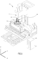
- an optical detecting apparatus for detecting a degree of freedom error of a spindle in accordance with the present invention is deposited between a spindle 11 and a platform 12 of a machine tool 10.
- the machine tool 10 at least has three linear axes (X-, Y- and Z-axes).
- the machine tool 10 is a multi-axis machine tool and the platform 12 is a rotating platform.
- the optical detecting apparatus has a standard bar 20, a sensor module 30, and a calculation unit 40.
- the sensor module 30 is operated with the standard bar 20, and the calculation unit 40 is used to calculate the detecting result of the sensor module 30 relative to the standard bar 20 by receiving the error signal of the sensor module 30 in electrical or wireless connection.
- the standard bar 20 is connected to the spindle 11 and the sensor module 30 is mounted on the platform 12.
- the standard bar 20 is a straight rod which is joined to a bottom end of the spindle 11 in a vertical and coaxial manner, and has a rod lens 21 and a reflection face 22.
- the rod lens 21 is a light transmitting cylinder, which may be a section on the standard bar 20 or an entire of the standard rod 20.
- the rod lens 21 constitutes the entire standard bar 20
- the reflection face 22 is formed at a free end of the rod lens 21 by coating, that is, the free end of the rod lens 21 is the bottom end of the standard test bar 20.
- the reflection face 22 is a horizontal plane.
- the sensor module 30 has a magnetic mount 31, a supporting base 32, a sensor frame 33, an primary detecting group 34, a minor detecting group 35, an oblique laser head 36, and a reflected spot displacement sensor 37.
- the magnetic mount 31 is deposited on a top face of the platform 12, and the supporting base 32 is deposited on the magnetic mount 31.
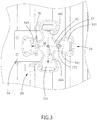
- the sensor frame 33 is deposited around the supporting base 32, and has four mounting boards 331. Two of the mounting boards 331 are deposited on the supporting base 32 and face to each other along the X-axis of the machine tool 10, and the other two mounting boards 331 are deposited on the supporting base 32 and face to each other along the Y-axis of the machine tool 10.
- Each one of the mounting boards 331 is a longitudinal board, and a measurement area 50 is formed between the mounting boards 331.
- the standard bar 20 extends into a center of the measurement area 50 between the mounting boards 331.
- the primary detecting group 34 is deposited on an upper portion of the sensor frame 33 around the measurement area 50, and has a first laser head 341, a second laser head 342, a first spot displacement sensor 343, and a second spot displacement sensor 344.
- the first laser head 341 and the first spot displacement sensor 343 are respectively mounted on the two mounting boards 331 of the sensor frame 33 that align with the X-axis of the machine tool 10, and the first laser head 341 has a center facing to a center of the first spot displacement sensor 343.
- the second laser head 342 and the second spot displacement sensor 344 are respectively mounted on the two mounting boards 331 of the sensor frame 33 that align with the Y-axis of the machine tool 10, and the second laser head 342 has a center facing to a center of the second spot displacement sensor 344.
- the minor detecting group 35 is deposited on a lower portion of the sensor frame 33 around the measurement area 50 below the primary detecting group 34, and has a third laser head 351, a fourth laser head 352, a third spot displacement sensor 353, and a fourth spot displacement sensor 354.
- the third laser head 351 and the third spot displacement sensor 353 are respectively mounted on the two mounting boards 331 of the sensor frame 33 that align with the X-axis of the machine tool 10, and the third laser head 351 has a center facing to a center of the third spot displacement sensor 353.
- the fourth laser head 352 and the fourth spot displacement sensor 354 are respectively mounted on the two mounting boards 331 of the sensor frame 33 that align with the Y axis of the machine tool 10, and the fourth laser head 352 has a center facing to a center of the fourth spot displacement sensor 354.
- the primary detecting group 34 and the minor detecting group 35 are deposited on the sensor frame 33 with an alignment of position up and down. With further reference to Fig. 5 , an assembling length L is defined between centers of the detecting groups 34, 35 along the Z-axis of the machine tool 10.
- the oblique spot laser head 36 and the reflected spot displacement sensor 37 are deposited on a top of the supporting base 32 in the measurement area 50, and align with the X-axis of the machine tool 10.
- the oblique spot laser head 36 is an obliquely cylindrical element and has a free end extending inwardly and upwardly
- the reflected spot displacement sensor 37 is an obliquely cylindrical element and has a free end extending inwardly and upwardly and a receiving face 371 deposited on the free end of the reflected spot displacement sensor 37.
- an angle between an axis line of the oblique spot laser head 36 and the horizontal plane is 45 degrees
- an angle between an axis line of the reflected spot displacement sensor 37 and the horizontal plane is 45 degrees.
- Each one of the spot displacement sensors 343, 344, 353, 354, 37 may be selected from one-dimensional or two-dimensional photoelectric sensor, position sensor, CCD sensor, CMOS sensor and other non-contact photoelectric sensor.
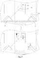
- the standard bar 20 and the sensor module 30 are deposited on the zero positions, and the laser lights of the first laser head 341 and the second laser head 342 are positive crossed at a center of the rod lens 21 adjacent to an upper portion of the rod lens 21, and the laser lights of the third laser head 351 and the fourth laser head 352 are positive crossed at the center of the rod lens 21 adjacent to a lower portion of the rod lens 21.
- the laser light of the oblique laser head 36 emits on a center of the reflection face 22 and reflects to a center of the receiving face 371 of the reflected spot displacement sensor 37.
- the standard bar 20 can be deposited at the center of the measurement area 50 by an instrument and a position of the reflection face 22 is adjusted upwardly or downwardly to enable the laser light of the oblique laser head 36 to reflect on the center of the reflection face 22 to the center of the receiving face 371 of the reflected spot displacement sensor 37.
- the standard bar 20 is moved along the Z-axis of the machine tool 10
- a distance ⁇ z of the standard bar 20 is defined by the standard bar 20 moving along the Z-axis of the machine tool 10
- the laser light of the first laser head 341 emits through the upper portion of the rod lens 21 and focus on the center of the first spot displacement sensor 343, and the laser light of the second laser head 342 emits through the upper portion of the rod lens 21 and focus on the center of the second spot displacement sensor 344.
- the laser light of the third laser head 351 emits through the lower portion of the rod lens 21 and focus on the center of the third spot displacement sensor 353, and the laser light of the fourth laser head 352 emits through the lower portion of the rod lens 21 and focus on the center of the fourth spot displacement sensor 354.
- the laser light of the oblique laser head 36 reflects on the reflection face 22 to the center of the receiving face 371 of the reflected spot displacement sensor 37 with an angle of 90 degrees.
- the internal components of the machine tool 10 may be thermally deformed by an internal heat source or an external heat source, so that the position of the spindle 11 is eccentric to cause the position of the standard bar 20 to move in the measurement area 50.
- the movement of the rod lens 21 at the lower portion of the rod lens 21 causes the two laser lights to be incident to change the focus positions on the third spot displacement sensor 353 and the fourth spot displacement sensor 354.
- the third light spot displacement sensor 353 can measure the Y-axis displacement change Y1 of the rod lens 21 at the lower portion
- the fourth spot displacement sensor 354 can measure the X-axis displacement change X1 of the rod lens 21 at the lower portion.
- the movement of the rod lens 21 at the upper portion of the rod lens 21 causes the two laser lights to be incident to change the focus positions on the first spot displacement sensor 343 and the second spot displacement sensor 344. Then, the first light spot displacement sensor 343 can measure the Y-axis displacement change Y2 of the rod lens 21 at the upper portion, and the second spot displacement sensor 344 can measure the X-axis displacement change X2 of the rod lens 21 at the upper portion.
- the standard bar 20 is moved in the measurement area 50 by the position of the eccentric of the spindle 11, with reference to Fig.
- the distance ⁇ z of the standard bar 20 that is moved along the Z-axis enables the reflection face 22 moving upwardly or downwardly, and this will change the position of the reflection face 22 that reflects the laser light to the receiving face 371.
- the receiving face 371 of the reflected spot displacement sensor 37 may detect the distance ⁇ x of the reflected laser light that moves relative to the center of the receiving face 371.
- the calculation unit 40 may be a single chip or a computer, and in the present embodiment, the calculation unit 40 is a computer, is received the signals of the X-axis displacement change X1 and the Y-axis displacement change Ylof the rod lens 21 at the lower portion and the distance ⁇ x of the reflected laser light that moves relative to the center of the receiving face 371 in electrical or wireless connection, and calculated with the known values of the assembling length L and the gain value K to get the errors of the spindle 11 and the rotation axis of the platform 12.
- the receiving face 371 of the reflected spot displacement sensor 37 is deposited with an angle of 45 degrees relative to the horizontal plane. Additionally, the angle between the receiving face 371 and the horizontal plane may be deposited with any other angles, such as 0 degree or 60 degrees, only the receiving face 371 can receive the reflected laser light of the reflection face 22. Furthermore, the angle between the axis line of the oblique spot laser head 36 and the horizontal plane is 45 degrees, and also can be any other angles, only the laser light of the oblique spot laser head 36 can emit on the reflection face 22 and reflect on the receiving face 371.
- the gain value K may be changed when the angles between the axis line of the oblique spot laser head 36 and the horizontal plane or the receiving face 371 and the horizontal plane are changed, and a new gain value K is needed to find via re-calibrated by the instrument.
- a detecting method in accordance with the present invention is used with the optical detecting apparatus for detecting a degree of freedom error of a spindle, and comprises a getting step, an assembling step, a zero step, a detecting step, and a calculating step.
- the standard bar 20 of the optical detecting apparatus is deposited at the center of the measurement area 50 of the sensor module 30 by the instrument .
- the position of the reflection face 22 is moved upwardly or downwardly to enable the laser light of the oblique laser head 36 to reflect on the center of the reflection face 22 to the center of the receiving face 371 of the reflected spot displacement sensor 37.
- the standard bar 20 is moved with the instrument along the Z-axis to get a ratio between the distance ⁇ z of the standard bar 20 moves along the Z-axis and the distance ⁇ x of the reflected laser light that moves relative to the center of the receiving face 371 by the instrument calibration mode , and the ratio is called the gain value K.
- the distance ⁇ z may be defined as a first distance and the distance ⁇ x may be defined as a second distance.
- the standard bar 20 of the optical detecting apparatus is assembled on a rotating spindle of a powered machinery, such as a bottom end of the spindle 11 of the machine tool 10, and the sensor module 30 is assembled on a platform of the powered machinery, such as the platform 12 of the machine tool 10, and the machine tool 10 is a multi-axes powered machinery with X-, Y- and Z-axes, and the platform 12 may be a biaxial platform or a rotating platform.
- the machine tool 10 is started to move the spindle 11 and the standard bar 20 to enable the standard bar 20 to move at the center of the measurement area 50 of the sensor module 30, the primary detecting group 34 is deposited around the rod lens 21 at the upper portion of the rod lens 21, the minor detecting group 35 is deposited around the rod lens 21 at the lower portion of the rod lens 21.
- the laser light of the first head 341 emits through the rod lens 21 and focus on the center of the first spot displacement sensor 343, the laser light of the second head 342 emits through the rod lens 21 and focus on the center of the second spot displacement sensor 344, the laser light of the third head 351 emits through the rod lens 21 and focus on the center of the third spot displacement sensor 353, the laser light of the fourth head 352 emits through the rod lens 21 and focus on the center of the fourth spot displacement sensor 354, and the laser light of the oblique laser head 36 emits on the center of the reflection face 21 of the standard bar 20 and reflects on the center of the receiving face 37 of the reflected spot displacement sensor 37.
- the spindle 11 is rotated by the machine tool 10, when the position of the standard bar 20 in the sensor module 30 is changed with the eccentricity of the spindle 11 that is rotated at high speed, a Y-axis displacement change Y1 of the rod lens 21 at the lower portion is detected by the third spot displacement sensor 353, a X-axis displacement change X1 of the rod lens 21 at the lower portion is detected by the fourth spot displacement sensor 354, a Y-axis displacement change Y2 of the rod lens 21 at the upper portion is detected by the first spot displacement sensor 343, a X-axis displacement change X2 of the rod lens 21 at the upper portion is detected by the second spot displacement sensor 342, and a distance ⁇ x of the reflected laser light that moves relative to the center of the receiving face 371 is detected by the receiving face 371 of the reflected spot displacement sensor 37.
- the signals of the displacement changes of X1, Y1, X2, Y2, and ⁇ x of the standard bar 20 that are detected by the sensor module 30 are transmitted to the calculation unit 40 in electrical or wireless connection, and substituted with the known values of the assembling length L and the gain value K into the following error program to calculate out the six degrees of freedom error of the spindle 11 and the rotation axis of the platform 12:
- the standard bar 20 is assembled on the bottom end of the spindle 11 of the machine tool 10 and the sensor module 30 is assembled on the platform 12 of the machine tool 10.
- the detecting method may detect six degrees of freedom error of the rotating spindle of the powered machinery, and respectively ⁇ x ( ⁇ ) , ⁇ y ( ⁇ ) , ⁇ z , ⁇ x ( ⁇ ), ⁇ y ( ⁇ ), and the angle deflection error (wobble ' ⁇ ).
- the optical detecting apparatus for detecting a degree of freedom error of a spindle and the detecting method thereof as described has the following advantages.
- the shape of the standard bar 20 is easy to manufacture, and the elements that are adopted for the sensor module 30, such as the primary detecting group 34 and the minor detecting group 35, are generally common optoelectronic elements. Therefore, the dynamic error detection device that is composed by the standard bar 20 and the sensor module 30 and the method of implementation are more inexpensive, and the risk of the possibility of implementation of the spindle 11 of the dynamic detection machine tool 10 can be drastically reduced.
- the present invention it is possible to detect the error changes of the spindle and the rotation axis rather than only detect the displacement changes of X-, Y- and Z-axes, and this may greatly improve the convenience of the present invention applied to the spindle and the rotation axis of the powered machinery, and widely used in the on-line detection of power machinery, when the detection of the present invention can be used to detect at least six degrees of freedom error.
Landscapes
- Physics & Mathematics (AREA)
- General Physics & Mathematics (AREA)
- Engineering & Computer Science (AREA)
- Mechanical Engineering (AREA)
- Optics & Photonics (AREA)
- Chemical & Material Sciences (AREA)
- Analytical Chemistry (AREA)
- Length Measuring Devices By Optical Means (AREA)
Claims (7)
- Optische Erfassungsvorrichtung zum Erfassen eines Freiheitsgradfehlers einer Spindel (11) einer angetriebenen Maschine mit X-, Y- und Z-Achse, wobei die optische Erfassungsvorrichtung eine Standardschiene (20) umfasst, die konfiguriert ist, um im Gebrauch mit der Spindel (11) verbunden zu werden, und ein Sensormodul (30), das konfiguriert ist, um im Gebrauch auf einer Plattform (12) der angetriebenen Maschine montiert zu werden:wobei die Standardschiene (20) eine gerade Stange ist und Folgendes aufweistein unteres Ende;eine Stablinse (21), die zylindrisch ist; undeine Reflexionsfläche (22), die am unteren Ende der Standardschiene (20) ausgebildet ist; undwobei das Sensormodul (30) mit der Standardschiene (20) betrieben wird und Folgendes aufweisteine Stützbasis (32);einen Sensorrahmen (33), der um die Stützbasis (32) herum angeordnet ist, um einen Messbereich (50) zwischen der Stützbasis (32) und dem Sensorrahmen (33) zum Einführen der Standardschiene (20) in den Messbereich (50) zu bilden, und der aufweisteine primäre Erfassungsgruppe (34), die auf dem Sensorrahmen (33) so angeordnet ist, dass sie im Gebrauch entlang der Z-Achse der angetriebenen Maschine angeordnet ist und Folgendes aufweisteinen ersten Laserkopf (341), der auf dem Sensorrahmen (33) so angeordnet ist, dass er im Gebrauch entlang der X-Achse der angetriebenen Maschine angeordnet ist;einen zweiten Laserkopf (342), der auf dem Sensorrahmen (33) so angeordnet ist, dass er im Gebrauch entlang der Y-Achse der angetriebenen Maschine angeordnet ist;einen ersten Punktverschiebungssensor (343), der auf dem Sensorrahmen (33) so angeordnet ist, dass er im Gebrauch entlang der X-Achse der angetriebenen Maschine und gegenüber dem ersten Laserkopf (341) angeordnet ist, um ein Laserlicht des ersten Kopfes (341) über die Stablinse (21) zu empfangen; undeinen zweiten Punktverschiebungssensor (344), der auf dem Sensorrahmen (33) so angeordnet ist, dass er im Gebrauch entlang der Y-Achse der angetriebenen Maschine und gegenüber dem zweiten Laserkopf (342) angeordnet ist, um ein Laserlicht des zweiten Kopfes (342) über die Stablinse (21) zu empfangen;eine kleine Erfassungsgruppe (35), die auf dem Sensorrahmen (33) so angeordnet ist, dass sie im Gebrauch entlang der Z-Achse der angetriebenen Maschine mit einem beabstandeten Intervall relativ zur primären Erfassungsgruppe (34) angeordnet ist und Folgendes aufweisteinen dritten Laserkopf (351), der auf dem Sensorrahmen (33) so angeordnet ist, dass er im Gebrauch entlang der X-Achse der angetriebenen Maschine angeordnet ist;einen vierten Laserkopf (352), der auf dem Sensorrahmen (33) so angeordnet ist, dass er im im Gebrauch entlang der Y-Achse der angetriebenen Maschine angeordnet;einen dritten Punktverschiebungssensor (353), der auf dem Sensorrahmen (33) so angeordnet ist, dass er im Gebrauch entlang der X-Achse der angetriebenen Maschine und gegenüber dem dritten Laserkopf (351) angeordnet ist, um ein Laserlicht des dritten Kopfes (351) über die Stablinse (21) zu empfangen; undeinen vierten Punktverschiebungssensor (354), der auf dem Sensorrahmen (33) so angeordnet ist, dass er im Gebrauch entlang der Y-Achse der angetriebenen Maschine und gegenüber dem vierten Laserkopf (352) angeordnet ist, um ein Laserlicht des vierten Kopfes (352) über die Stablinse (21) zu empfangen;wobei die optische Erfassungsvorrichtung dadurch gekennzeichnet ist, dass:das Sensormodul (30) eine Magnethalterung (31) aufweist, auf der die Stützbasis (32) angeordnet ist, wobei die Magnethalterung (31) so ausgelegt ist, dass sie auf der Plattform (12) der angetriebenen Maschine angeordnet werden kann;der Sensorrahmen (33) weiterhin aufweist:einen schrägen Laserkopf (36), der auf der Stützfläche (32) angeordnet ist und ein freies Ende aufweist, das sich im Messbereich (50) nach innen und oben erstreckt; undeinen reflektierten Punktverschiebungssensor (37), der auf der Stützbasis (32) im Messbereich (50) angeordnet ist und eine Empfangsfläche (371) zum Empfangen eines Laserlichts des schrägen Laserkopfes (36) aufweist, das von der Reflexionsfläche (22) der Standardschiene (20) in einem Winkel von 90 Grad reflektiert wird.
- Optische Erfassungsvorrichtung nach Anspruch 1, bei der
der Sensorrahmen (33) vier Montageplatten (331) aufweist, zwei der Montageplatten (331) auf der Stützbasis (32) und einander zugewandt entlang der X-Achse der angetriebenen Maschine im Gebrauch angeordnet sind, die anderen beiden Montageplatten (331) auf der Stützbasis (32) und einander zugewandt entlang der Y-Achse der angetriebenen Maschine im Gebrauch angeordnet sind, und jede der vier Montageplatten (331) einen oberen Abschnitt und einen unteren Abschnitt aufweist;
der Messbereich (50) im Sensormodul (30) zwischen den vier Montageplatten (331) ausgebildet ist;
jeder des ersten Laserkopfes (341), des zweite Laserkopfes (342), des ersten Punktverschiebungssensors (343) und des zweiten Punktverschiebungssensors (344) auf einer der vier Montageplatten (331) des Sensorrahmens (33) montiert ist; und
jeder des dritten Laserkopfes (351), des vierten Laserkopfer (352), des dritten Punktverschiebungssensors (353) und des vierten Punktverschiebungssensors (354) auf einer der vier Montageplatten (331) des Sensorrahmens (33) montiert ist. - Optische Erfassungsvorrichtung nach Anspruch 2, bei der
die primäre Erfassungsgruppe (34) auf dem Sensormodul (30) an den oberen Abschnitten der vier Montageplatten (331) angeordnet ist;
die kleine Erfassungsgruppe (35) auf dem Sensormodul (30) an den unteren Abschnitten der vier Montageplatten (331) angeordnet ist;
die Standardschiene (20) einen oberen Abschnitt und einen unteren Abschnitt aufweist, wobei die Standardschiene (20) angepasst ist, um in den Messbereich (50) eingeführt zu werden, der obere Abschnitt der Standardschiene (20) angrenzend an die primäre Erfassungsgruppe (34) angeordnet ist und der untere Abschnitt der Standardschiene (20) angrenzend an die kleine Erfassungsgruppe (35) angeordnet ist;
die Reflexionsfläche (22) der Standardschiene (20) über dem schrägen Laserkopf (36) und dem reflektierten Punktverschiebungssensor (37) angeordnet ist; und
der schräge Laserkopf (36) konfiguriert ist, um ein Laserlicht auf ein Zentrum der Reflexionsfläche (22) zu emittieren, wobei die Reflexionsfläche (22) konfiguriert ist, um das Laserlicht so zu reflektieren, dass es sich auf ein Zentrum der Empfangsfläche (371) konzentriert. - Optische Erfassungsvorrichtung nach Anspruch 3, bei der
der schräge Laserkopf (36) und der reflektierte Punktverschiebungssensor (37) symmetrisch im Messbereich (50) der Standardschiene (20) angeordnet sind;
der schräge Laserkopf (36) ein schräg zylindrisches Element ist und einen Winkel zwischen einer Achsenlinie des schrägen Punktlaserkopfes (36) und der horizontalen Ebene von 45 Grad aufweist;
der reflektierte Punktverschiebungssensor (37) ein schräg zylindrisches Element ist; und
die Empfangsfläche (371) auf einem freien Ende des reflektierten Punktverschiebungssensors (37) angeordnet ist und einen Winkel relativ zur horizontalen Ebene von 45 Grad aufweist. - Optische Erfassungsvorrichtung nach einem der Ansprüche 1 bis 4, wobei jeder der Punktverschiebungssensoren (343, 344, 353, 354, 37) ausgewählt ist aus eindimensionalem photoelektrischem Sensor, zweidimensionalem photoelektrischem Sensor, Positionssensor, CCD-Sensor und CMOS-Sensor.
- Optisches Erfassungsverfahren zum Erfassen eines Freiheitsgradfehlers einer Spindel (11) einer angetriebenen Maschine mit X-, Y- und Z-Achse, dadurch gekennzeichnet, dass das optische Erfassungsverfahren umfasst:einen Montageschritt, umfassendBereitstellen einer optischen Erfassungsvorrichtung nach Anspruch 1;Montieren der Standardschiene (20) auf der Spindel (11) der angetriebenen Maschine;Montieren des Sensormoduls (30) auf einer Plattform (12) der angetriebenen Maschine; undDefinieren einer Zusammenbaulänge (L) zwischen einer Mitte der primären Erfassungsgruppe (34) und einer Mitte der kleinen Erfassungsgruppe (35) entlang der Z-Achse der angetriebenen Maschine;einen Nullschritt, umfassend
Bewegen der Standardschiene (20) in einer Mitte des Messbereichs (50) des Sensormoduls (30), um zu ermöglichen, dass das Laserlicht des ersten Laserkopfes (341) durch die Stablinse (21) emittiert und auf eine Mitte des ersten Punktverschiebungssensors (343) fokussiert wird, um zu ermöglichen, dass das Laserlicht des zweiten Laserkopfes (342) durch die Stablinse (21) emittiert und auf eine Mitte des zweiten Punktverschiebungssensors (344) fokussiert wird, um zu ermöglichen, dass das das Laserlicht des dritten Laserkopfes (351) durch die Stablinse (21) emittiert und auf ein Zentrum des dritten Punktverschiebungssensors (353) fokussiert wird, und um zu ermöglichen, dass das Laserlicht des vierten Laserkopfes (352) durch die Stablinse (21) emittiert und auf ein Zentrum des vierten Punktverschiebungssensors (354) fokussiert wird;einen Detektionsschritt, umfassendDrehen der Spindel (11) durch die angetriebene Maschine;Erfassen einer Y-Achsenverschiebungsänderung (Y1) der Stablinse (21) am unteren Abschnitt durch den dritten Punktverschiebungssensor (353), einer X-Achsenverschiebungsänderung (X1) der Stablinse (21) am unteren Abschnitt durch den vierten Punktverschiebungssensor (354), eine Y-Achsenverschiebungsänderung (Y2) der Stablinse (21) am oberen Abschnitt durch den ersten Punktverschiebungssensor (343) und eine X-Achsenverschiebungsänderung (X2) der Stablinse (21) am oberen Abschnitt durch den zweiten Punktverschiebungssensor (344), wenn die Position der Standardschiene (20) mit der Exzentrizität der Spindel (11) verändert wird; undeinen Berechnungsschritt, umfassendÜbertragen der vom Sensormodul (30) erfassten Signale der Verschiebungsänderungen (X1, Y1, X2, Y2) der Standardschiene (20) an eine Berechnungseinheit (40); undErsetzen mit den bekannten Werten der Montagelänge (L) in ein Fehlerprogramm zum Berechnen der sechs Freiheitsgradfehler der Spindel (11) und einer Drehachse der Plattform (12);wobei das optische Detektionsverfahren dadurch gekennzeichnet ist, dass:der Nullschritt umfasst:Einstellen einer Position der Reflexionsfläche (22), um es dem Laserlicht des schrägen Laserkopfes (36) zu ermöglichen, auf einer Mitte der Reflexionsfläche (22) zu einer Mitte der Empfangsfläche des reflektierten Punktverschiebungssensors (37) mit einem Winkel von 90 Grad zu reflektieren;Bewegen der Standardschiene (20) entlang der Z-Achse, um einen ersten Abstand zu erzeugen;Erfassen eines zweiten Abstands des reflektierten Laserlichts, das sich relativ zur Mitte der Empfangsfläche (371) durch den reflektierten Punktverschiebungssensor (37) bewegt; undDefinieren eines Verstärkungswerts (K), der ein Verhältnis der ersten Entfernung zur zweiten Entfernung ist;der Erfassungsschritt ferner das Erfassen eines Abstands (Δx) des reflektierten Laserlichts, das sich relativ zur Mitte der Empfangsfläche (371) durch die Empfangsfläche (371) des reflektierten Punktverschiebungssensors (37) bewegt, wenn die Position der Standardschiene (20) mit der Exzentrizität der Spindel (11) verändert wird;der Berechnungsschritt ferner das Ersetzen des bekannten Wertes der Montagelänge (L) und der Verstärkung (K) im folgenden Fehlerprogramm umfasst:den Radialfehler in Richtung der X-Achse: δx (θ) =X1;der Radialfehler in Richtung der Y-Achse: δy (θ) =Y1der Radialfehler in Richtung der Z-Achse: Δz=K∗Δx;der Winkelablenkfehler: der Winkelpositionierungsfehler in Richtung der X-Achse:
 der Winkelpositionierungsfehler in Richtung der Y-Achse:
- Optisches Erfassungsverfahren nach Anspruch 6, worin das optische Erfassungsverfahren einen Get-Schritt vor dem Montageschritt aufweist und der Get-Schritt umfasst
Anordnen der Standardschiene (20) der optischen Erfassungsvorrichtung in der Mitte des Messbereichs (50) des Sensormoduls (30) durch ein Instrument;
Bewegen der Reflexionsfläche (22), um zu ermöglichen, dass das Laserlicht des schrägen Laserkopfes (36) auf die Mitte der Reflexionsfläche (22) emittiert und auf die Mitte der Empfangsfläche (371) des reflektierten Punktverschiebungssensors (37) reflektiert wird;
Bewegen der Standardschiene (20) mit dem Instrument entlang der Z-Achse, um ein Verhältnis zu erhalten, wenn sich der Verstärkungswert (K) zwischen dem Abstand (Δz) der Standardschiene (20) entlang der Z-Achse und dem Abstand (Δx) des reflektierten Laserlichts, das sich relativ zur Mitte der Empfangsfläche (371) durch einen Instrumentenkalibriermodus bewegt, bewegt.
Applications Claiming Priority (1)
| Application Number | Priority Date | Filing Date | Title |
|---|---|---|---|
| TW106112744A TWI632344B (zh) | 2017-04-17 | 2017-04-17 | 光學式轉軸多自由度誤差檢測裝置與方法(二) |
Publications (2)
| Publication Number | Publication Date |
|---|---|
| EP3392609A1 EP3392609A1 (de) | 2018-10-24 |
| EP3392609B1 true EP3392609B1 (de) | 2019-09-18 |
Family
ID=59416525
Family Applications (1)
| Application Number | Title | Priority Date | Filing Date |
|---|---|---|---|
| EP17180396.8A Active EP3392609B1 (de) | 2017-04-17 | 2017-07-07 | Optische detektionsvorrichtung zur detektion eines fehlers des freiheitsgrades einer spindel und detektionsverfahren dafür |
Country Status (6)
| Country | Link |
|---|---|
| US (1) | US10571259B2 (de) |
| EP (1) | EP3392609B1 (de) |
| JP (1) | JP6385531B1 (de) |
| KR (1) | KR102005626B1 (de) |
| CN (1) | CN108731595B (de) |
| TW (1) | TWI632344B (de) |
Families Citing this family (23)
| Publication number | Priority date | Publication date | Assignee | Title |
|---|---|---|---|---|
| US10900779B2 (en) * | 2018-01-23 | 2021-01-26 | Dalian University Of Technology | Method for the rapid detection of the linear axis angular error of an NC machine tool |
| CN110686873B (zh) * | 2018-06-20 | 2022-01-18 | 苏州巨佳电子科技有限公司 | 一种笔记本转轴质量检测装置及方法 |
| CN110081823B (zh) * | 2019-06-06 | 2024-01-26 | 合肥工业大学 | 一种机床五自由度几何运动误差测量系统 |
| US11193760B2 (en) | 2019-07-02 | 2021-12-07 | Redalign Llc | Apparatus and method for coaxially aligning two rotatable shafts |
| US11650048B2 (en) | 2019-07-02 | 2023-05-16 | Redalign Llc | Apparatus and method for coaxtailly aligning two rotatable shafts |
| TWI717162B (zh) * | 2019-12-20 | 2021-01-21 | 國家中山科學研究院 | 一種多軸加工裝置及其補償方法 |
| CN111580460B (zh) * | 2020-06-05 | 2023-05-16 | 沈机(上海)智能系统研发设计有限公司 | 五轴机床的误差检测系统、误差检测和补偿方法 |
| CN111721199B (zh) * | 2020-06-10 | 2021-10-26 | 合肥工业大学 | 旋转轴五自由度误差运动的精密测量装置及方法 |
| CN111906817A (zh) * | 2020-07-31 | 2020-11-10 | 浙江工贸职业技术学院 | 一种六自由度工业机器误差检测系统 |
| CN114076930A (zh) * | 2020-08-21 | 2022-02-22 | 广东博智林机器人有限公司 | 调节装置及调节方法 |
| KR102774436B1 (ko) * | 2021-11-30 | 2025-03-04 | (주)딥골프 | 기울기 측정 장치 |
| TWI761126B (zh) * | 2021-03-12 | 2022-04-11 | 國立虎尾科技大學 | 線上工件尺寸與幾何精度檢測裝置 |
| CN113280759B (zh) * | 2021-04-20 | 2022-04-08 | 南京航空航天大学 | 一种过载模拟转台及转轴同轴度检测校准装置 |
| CN113551881B (zh) * | 2021-07-16 | 2023-02-10 | 中国科学院长春光学精密机械与物理研究所 | 高精度六自由度光学组件性能测试方法 |
| CN113375907A (zh) * | 2021-07-16 | 2021-09-10 | 中国科学院长春光学精密机械与物理研究所 | 一种高精度六自由度光学组件的性能测试系统 |
| CN115686077A (zh) * | 2021-07-26 | 2023-02-03 | 三赢科技(深圳)有限公司 | 水平校正方法、电子装置及存储介质 |
| CN113639671B (zh) * | 2021-08-07 | 2024-03-15 | 电科睿视技术(北京)有限公司 | 一种用于x射线管的角度检测装置及其使用方法 |
| KR102593770B1 (ko) * | 2021-10-15 | 2023-10-24 | 경일대학교산학협력단 | 5축 공작기계의 이송축 사이의 오차 측정장치 및 측정방법 |
| TWI837533B (zh) * | 2021-10-27 | 2024-04-01 | 財團法人工業技術研究院 | 十字雷射校正裝置及應用其之校正系統 |
| CN115265367B (zh) * | 2022-08-09 | 2023-08-25 | 淮阴师范学院 | 一种测量转轴自由度误差的光学测量装置 |
| CN116372601A (zh) * | 2023-05-24 | 2023-07-04 | 珠海格力智能装备技术研究院有限公司 | 数控机床调平结构和调平方法 |
| CN117245555A (zh) * | 2023-08-04 | 2023-12-19 | 天津大学 | 精密立式磨床热致主轴-转台轴线偏差测量装置与方法 |
| CN117620772B (zh) * | 2023-12-12 | 2026-04-14 | 吉林大学 | 一种数控机床动态精度检测装置 |
Family Cites Families (35)
| Publication number | Priority date | Publication date | Assignee | Title |
|---|---|---|---|---|
| GB8706388D0 (en) * | 1987-03-18 | 1987-04-23 | Meta Machines Ltd | Position sensing method |
| US4942539A (en) * | 1988-12-21 | 1990-07-17 | Gmf Robotics Corporation | Method and system for automatically determining the position and orientation of an object in 3-D space |
| US5278634A (en) * | 1991-02-22 | 1994-01-11 | Cyberoptics Corporation | High precision component alignment sensor system |
| US5432605A (en) * | 1993-07-19 | 1995-07-11 | Tsi Incorporated | Interferometric cylinder sizing and velocimetry device |
| JPH07260425A (ja) * | 1994-03-17 | 1995-10-13 | Union Tool Kk | 回転体の振れ測定装置 |
| JP3583468B2 (ja) * | 1994-05-31 | 2004-11-04 | 東芝ソリューション株式会社 | 軸芯ずれ測定装置 |
| TW376446B (en) * | 1998-04-10 | 1999-12-11 | mu-rong Chen | Six-degree-of-freedom measurement apparatus and method |
| KR100479412B1 (ko) * | 2002-11-13 | 2005-03-31 | 한국기계연구원 | 진직도 측정 장치 |
| US8203702B1 (en) * | 2005-06-13 | 2012-06-19 | ARETé ASSOCIATES | Optical system |
| TWI260394B (en) * | 2005-08-24 | 2006-08-21 | Univ Nat Formosa | Error-measuring apparatus for nano-scale rotary axle |
| CN2884141Y (zh) * | 2005-12-30 | 2007-03-28 | 北京交通大学 | 一种激光六自由度同时测量装置 |
| TWI285254B (en) * | 2006-07-05 | 2007-08-11 | Univ Nat Formosa | High precision rotation revolving thermal deformation measurement system |
| TWI287616B (en) * | 2006-07-14 | 2007-10-01 | Univ Nat Formosa | Measuring error method for high precision and nano-scale rotation axis and the apparatus thereof |
| US8306747B1 (en) * | 2007-01-19 | 2012-11-06 | Starodub, Inc. | Travel way measurement system |
| CA2597891A1 (en) * | 2007-08-20 | 2009-02-20 | Marc Miousset | Multi-beam optical probe and system for dimensional measurement |
| JP2009068972A (ja) * | 2007-09-12 | 2009-04-02 | Institute Of National Colleges Of Technology Japan | 回転振れ及び形状測定装置 |
| AU2009211435A1 (en) * | 2008-02-04 | 2009-08-13 | Tele Atlas B.V. | Method for map matching with sensor detected objects |
| WO2010108168A2 (en) * | 2009-03-20 | 2010-09-23 | Mts Systems Corporation | Multiple degree of freedom displacement transducer |
| JP5275866B2 (ja) * | 2009-03-25 | 2013-08-28 | 正人 明田川 | 5自由度誤差測定装置 |
| JP2011013149A (ja) * | 2009-07-03 | 2011-01-20 | Kagoshima Univ | 回転精度測定方法及び測定装置 |
| TW201121700A (en) * | 2009-12-29 | 2011-07-01 | Univ Nat Formosa | Measurement device for multi-axis machine tool. |
| US8643850B1 (en) * | 2010-03-02 | 2014-02-04 | Richard L. Hartman | Automated system for load acquisition and engagement |
| KR101210911B1 (ko) * | 2010-12-08 | 2012-12-12 | 광주과학기술원 | 이송장치의 운동 오차 측정 기능을 겸비한 5자유도 운동 측정 장치 |
| CN102689234B (zh) * | 2012-06-08 | 2014-04-30 | 合肥工业大学 | 一种滚齿机床热误差的检测装置及检测方法 |
| US9772181B2 (en) * | 2013-01-09 | 2017-09-26 | Carl Zeiss Industrielle Messtechnik Gmbh | Test body for determining rotation errors of a rotating apparatus |
| US20160252325A1 (en) * | 2013-10-08 | 2016-09-01 | Horus Vision Llc | Compositions, methods and systems for external and internal environmental sensing |
| EP2878920A1 (de) * | 2013-11-28 | 2015-06-03 | Hexagon Technology Center GmbH | Kalibrierung einer Koordinatenmessmaschine mithilfe eines Kalibrierungslaserkopfs am Werkzeugmittelspunkt |
| US10101454B2 (en) * | 2014-01-15 | 2018-10-16 | University of Pittsburgh—of the Commonwealth System of Higher Education | Pathway measurement devices, systems and methods |
| CN203798284U (zh) * | 2014-05-06 | 2014-08-27 | 湖南南方宇航高精传动有限公司 | 一种大直径测量装置 |
| US10246742B2 (en) * | 2015-05-20 | 2019-04-02 | Quantum-Si Incorporated | Pulsed laser and bioanalytic system |
| CN204757949U (zh) * | 2015-05-29 | 2015-11-11 | 中国工程物理研究院总体工程研究所 | 成套回转装备主轴动态回转误差的测量装置 |
| CN105180819B (zh) * | 2015-10-21 | 2018-01-12 | 天津大学 | 基于激光位移传感器的轴径测量装置及其测量方法 |
| JP2017154202A (ja) * | 2016-03-01 | 2017-09-07 | 三菱電機株式会社 | エンドミルによる加工方法および加工装置 |
| CA3047133A1 (en) * | 2016-12-16 | 2018-06-21 | Quantum-Si Incorporated | Compact mode-locked laser module |
| US11074463B2 (en) * | 2017-05-02 | 2021-07-27 | Qualcomm Incorporated | Dynamic sensor operation and data processing based on motion information |
-
2017
- 2017-04-17 TW TW106112744A patent/TWI632344B/zh active
- 2017-06-19 US US15/627,411 patent/US10571259B2/en active Active
- 2017-06-21 CN CN201710473144.2A patent/CN108731595B/zh active Active
- 2017-07-07 EP EP17180396.8A patent/EP3392609B1/de active Active
- 2017-07-10 JP JP2017134947A patent/JP6385531B1/ja active Active
- 2017-07-24 KR KR1020170093623A patent/KR102005626B1/ko active Active
Non-Patent Citations (1)
| Title |
|---|
| None * |
Also Published As
| Publication number | Publication date |
|---|---|
| CN108731595B (zh) | 2020-04-21 |
| KR102005626B1 (ko) | 2019-07-30 |
| JP2018179958A (ja) | 2018-11-15 |
| TW201839354A (zh) | 2018-11-01 |
| JP6385531B1 (ja) | 2018-09-05 |
| EP3392609A1 (de) | 2018-10-24 |
| CN108731595A (zh) | 2018-11-02 |
| US20180299263A1 (en) | 2018-10-18 |
| US10571259B2 (en) | 2020-02-25 |
| TWI632344B (zh) | 2018-08-11 |
Similar Documents
| Publication | Publication Date | Title |
|---|---|---|
| EP3392609B1 (de) | Optische detektionsvorrichtung zur detektion eines fehlers des freiheitsgrades einer spindel und detektionsverfahren dafür | |
| JP2779242B2 (ja) | 光電子工学式角度測定システム | |
| EP1086354B1 (de) | Vorrichtung zur oberflächenabtastung mit optischem sensor | |
| CN101587241B (zh) | 光束扫描装置、激光加工装置、测试方法和激光加工方法 | |
| US10690487B2 (en) | Profile inspection system for threaded and axial components | |
| US7812970B2 (en) | Method and system for inspecting parts utilizing triangulation | |
| US11187521B2 (en) | Rotating chromatic range sensor system with calibration object and method | |
| US10712147B2 (en) | Measurement system and method of manufacturing shaft with hole | |
| JP2003156405A (ja) | 非球面レンズの偏心測定方法及び偏心測定装置 | |
| JP2007071852A (ja) | 深穴測定装置および深穴測定方法 | |
| US20220074732A1 (en) | Noncontact sensor calibration using single axis movement | |
| KR100991353B1 (ko) | 코너큐브프리즘과 파장판을 이용한 레이저 동심도 및 직각도 동시측정장치 | |
| JPS6126601B2 (de) | ||
| JP2001157951A (ja) | 逐次2点法による形状精度測定装置および逐次2点法による形状精度測定用レーザ変位計間隔測定方法 | |
| Li et al. | Method for simultaneously and directly measuring all six-DOF motion errors of a rotary axis | |
| Park et al. | A new optical measurement system for determining the geometrical errors of rotary axis of a 5-axis miniaturized machine tool | |
| US4836031A (en) | Method and apparatus for measuring deformations of test samples in testing machines | |
| Tong et al. | A novel laser-based system for measuring internal thread parameters | |
| TWM545243U (zh) | 光學式轉軸多自由度誤差檢測裝置 | |
| TW201839353A (zh) | 光學式轉軸多自由度誤差檢測裝置與方法(一) | |
| CN221959531U (zh) | 光斑旋转编码器装置 | |
| CN221957995U (zh) | 精密定位的直线导轨装置 | |
| EP1805482B1 (de) | Verfahren und system zur bestimmung der eigenschaften einer rotationsfläche | |
| KR100286648B1 (ko) | 3차원형상검출방법 | |
| CN120445275A (zh) | 设置光斑旋转编码器的方法及其装置 |
Legal Events
| Date | Code | Title | Description |
|---|---|---|---|
| PUAI | Public reference made under article 153(3) epc to a published international application that has entered the european phase |
Free format text: ORIGINAL CODE: 0009012 |
|
| STAA | Information on the status of an ep patent application or granted ep patent |
Free format text: STATUS: REQUEST FOR EXAMINATION WAS MADE |
|
| 17P | Request for examination filed |
Effective date: 20170804 |
|
| AK | Designated contracting states |
Kind code of ref document: A1 Designated state(s): AL AT BE BG CH CY CZ DE DK EE ES FI FR GB GR HR HU IE IS IT LI LT LU LV MC MK MT NL NO PL PT RO RS SE SI SK SM TR |
|
| AX | Request for extension of the european patent |
Extension state: BA ME |
|
| GRAP | Despatch of communication of intention to grant a patent |
Free format text: ORIGINAL CODE: EPIDOSNIGR1 |
|
| STAA | Information on the status of an ep patent application or granted ep patent |
Free format text: STATUS: GRANT OF PATENT IS INTENDED |
|
| INTG | Intention to grant announced |
Effective date: 20190408 |
|
| GRAS | Grant fee paid |
Free format text: ORIGINAL CODE: EPIDOSNIGR3 |
|
| GRAA | (expected) grant |
Free format text: ORIGINAL CODE: 0009210 |
|
| STAA | Information on the status of an ep patent application or granted ep patent |
Free format text: STATUS: THE PATENT HAS BEEN GRANTED |
|
| AK | Designated contracting states |
Kind code of ref document: B1 Designated state(s): AL AT BE BG CH CY CZ DE DK EE ES FI FR GB GR HR HU IE IS IT LI LT LU LV MC MK MT NL NO PL PT RO RS SE SI SK SM TR |
|
| REG | Reference to a national code |
Ref country code: GB Ref legal event code: FG4D |
|
| REG | Reference to a national code |
Ref country code: CH Ref legal event code: EP |
|
| REG | Reference to a national code |
Ref country code: DE Ref legal event code: R096 Ref document number: 602017007114 Country of ref document: DE |
|
| REG | Reference to a national code |
Ref country code: AT Ref legal event code: REF Ref document number: 1181856 Country of ref document: AT Kind code of ref document: T Effective date: 20191015 |
|
| REG | Reference to a national code |
Ref country code: IE Ref legal event code: FG4D |
|
| REG | Reference to a national code |
Ref country code: NL Ref legal event code: MP Effective date: 20190918 |
|
| PG25 | Lapsed in a contracting state [announced via postgrant information from national office to epo] |
Ref country code: LT Free format text: LAPSE BECAUSE OF FAILURE TO SUBMIT A TRANSLATION OF THE DESCRIPTION OR TO PAY THE FEE WITHIN THE PRESCRIBED TIME-LIMIT Effective date: 20190918 Ref country code: HR Free format text: LAPSE BECAUSE OF FAILURE TO SUBMIT A TRANSLATION OF THE DESCRIPTION OR TO PAY THE FEE WITHIN THE PRESCRIBED TIME-LIMIT Effective date: 20190918 Ref country code: BG Free format text: LAPSE BECAUSE OF FAILURE TO SUBMIT A TRANSLATION OF THE DESCRIPTION OR TO PAY THE FEE WITHIN THE PRESCRIBED TIME-LIMIT Effective date: 20191218 Ref country code: NO Free format text: LAPSE BECAUSE OF FAILURE TO SUBMIT A TRANSLATION OF THE DESCRIPTION OR TO PAY THE FEE WITHIN THE PRESCRIBED TIME-LIMIT Effective date: 20191218 Ref country code: SE Free format text: LAPSE BECAUSE OF FAILURE TO SUBMIT A TRANSLATION OF THE DESCRIPTION OR TO PAY THE FEE WITHIN THE PRESCRIBED TIME-LIMIT Effective date: 20190918 Ref country code: FI Free format text: LAPSE BECAUSE OF FAILURE TO SUBMIT A TRANSLATION OF THE DESCRIPTION OR TO PAY THE FEE WITHIN THE PRESCRIBED TIME-LIMIT Effective date: 20190918 |
|
| REG | Reference to a national code |
Ref country code: LT Ref legal event code: MG4D |
|
| PG25 | Lapsed in a contracting state [announced via postgrant information from national office to epo] |
Ref country code: RS Free format text: LAPSE BECAUSE OF FAILURE TO SUBMIT A TRANSLATION OF THE DESCRIPTION OR TO PAY THE FEE WITHIN THE PRESCRIBED TIME-LIMIT Effective date: 20190918 Ref country code: GR Free format text: LAPSE BECAUSE OF FAILURE TO SUBMIT A TRANSLATION OF THE DESCRIPTION OR TO PAY THE FEE WITHIN THE PRESCRIBED TIME-LIMIT Effective date: 20191219 Ref country code: AL Free format text: LAPSE BECAUSE OF FAILURE TO SUBMIT A TRANSLATION OF THE DESCRIPTION OR TO PAY THE FEE WITHIN THE PRESCRIBED TIME-LIMIT Effective date: 20190918 Ref country code: LV Free format text: LAPSE BECAUSE OF FAILURE TO SUBMIT A TRANSLATION OF THE DESCRIPTION OR TO PAY THE FEE WITHIN THE PRESCRIBED TIME-LIMIT Effective date: 20190918 |
|
| REG | Reference to a national code |
Ref country code: AT Ref legal event code: MK05 Ref document number: 1181856 Country of ref document: AT Kind code of ref document: T Effective date: 20190918 |
|
| PG25 | Lapsed in a contracting state [announced via postgrant information from national office to epo] |
Ref country code: PT Free format text: LAPSE BECAUSE OF FAILURE TO SUBMIT A TRANSLATION OF THE DESCRIPTION OR TO PAY THE FEE WITHIN THE PRESCRIBED TIME-LIMIT Effective date: 20200120 Ref country code: PL Free format text: LAPSE BECAUSE OF FAILURE TO SUBMIT A TRANSLATION OF THE DESCRIPTION OR TO PAY THE FEE WITHIN THE PRESCRIBED TIME-LIMIT Effective date: 20190918 Ref country code: NL Free format text: LAPSE BECAUSE OF FAILURE TO SUBMIT A TRANSLATION OF THE DESCRIPTION OR TO PAY THE FEE WITHIN THE PRESCRIBED TIME-LIMIT Effective date: 20190918 Ref country code: AT Free format text: LAPSE BECAUSE OF FAILURE TO SUBMIT A TRANSLATION OF THE DESCRIPTION OR TO PAY THE FEE WITHIN THE PRESCRIBED TIME-LIMIT Effective date: 20190918 Ref country code: EE Free format text: LAPSE BECAUSE OF FAILURE TO SUBMIT A TRANSLATION OF THE DESCRIPTION OR TO PAY THE FEE WITHIN THE PRESCRIBED TIME-LIMIT Effective date: 20190918 Ref country code: IT Free format text: LAPSE BECAUSE OF FAILURE TO SUBMIT A TRANSLATION OF THE DESCRIPTION OR TO PAY THE FEE WITHIN THE PRESCRIBED TIME-LIMIT Effective date: 20190918 Ref country code: RO Free format text: LAPSE BECAUSE OF FAILURE TO SUBMIT A TRANSLATION OF THE DESCRIPTION OR TO PAY THE FEE WITHIN THE PRESCRIBED TIME-LIMIT Effective date: 20190918 Ref country code: ES Free format text: LAPSE BECAUSE OF FAILURE TO SUBMIT A TRANSLATION OF THE DESCRIPTION OR TO PAY THE FEE WITHIN THE PRESCRIBED TIME-LIMIT Effective date: 20190918 |
|
| PG25 | Lapsed in a contracting state [announced via postgrant information from national office to epo] |
Ref country code: SM Free format text: LAPSE BECAUSE OF FAILURE TO SUBMIT A TRANSLATION OF THE DESCRIPTION OR TO PAY THE FEE WITHIN THE PRESCRIBED TIME-LIMIT Effective date: 20190918 Ref country code: SK Free format text: LAPSE BECAUSE OF FAILURE TO SUBMIT A TRANSLATION OF THE DESCRIPTION OR TO PAY THE FEE WITHIN THE PRESCRIBED TIME-LIMIT Effective date: 20190918 Ref country code: IS Free format text: LAPSE BECAUSE OF FAILURE TO SUBMIT A TRANSLATION OF THE DESCRIPTION OR TO PAY THE FEE WITHIN THE PRESCRIBED TIME-LIMIT Effective date: 20200224 Ref country code: CZ Free format text: LAPSE BECAUSE OF FAILURE TO SUBMIT A TRANSLATION OF THE DESCRIPTION OR TO PAY THE FEE WITHIN THE PRESCRIBED TIME-LIMIT Effective date: 20190918 |
|
| REG | Reference to a national code |
Ref country code: DE Ref legal event code: R097 Ref document number: 602017007114 Country of ref document: DE |
|
| PLBE | No opposition filed within time limit |
Free format text: ORIGINAL CODE: 0009261 |
|
| STAA | Information on the status of an ep patent application or granted ep patent |
Free format text: STATUS: NO OPPOSITION FILED WITHIN TIME LIMIT |
|
| PG2D | Information on lapse in contracting state deleted |
Ref country code: IS |
|
| PG25 | Lapsed in a contracting state [announced via postgrant information from national office to epo] |
Ref country code: DK Free format text: LAPSE BECAUSE OF FAILURE TO SUBMIT A TRANSLATION OF THE DESCRIPTION OR TO PAY THE FEE WITHIN THE PRESCRIBED TIME-LIMIT Effective date: 20190918 Ref country code: IS Free format text: LAPSE BECAUSE OF FAILURE TO SUBMIT A TRANSLATION OF THE DESCRIPTION OR TO PAY THE FEE WITHIN THE PRESCRIBED TIME-LIMIT Effective date: 20200119 |
|
| 26N | No opposition filed |
Effective date: 20200619 |
|
| PG25 | Lapsed in a contracting state [announced via postgrant information from national office to epo] |
Ref country code: MC Free format text: LAPSE BECAUSE OF FAILURE TO SUBMIT A TRANSLATION OF THE DESCRIPTION OR TO PAY THE FEE WITHIN THE PRESCRIBED TIME-LIMIT Effective date: 20190918 |
|
| REG | Reference to a national code |
Ref country code: BE Ref legal event code: MM Effective date: 20200731 |
|
| PG25 | Lapsed in a contracting state [announced via postgrant information from national office to epo] |
Ref country code: LU Free format text: LAPSE BECAUSE OF NON-PAYMENT OF DUE FEES Effective date: 20200707 Ref country code: IE Free format text: LAPSE BECAUSE OF NON-PAYMENT OF DUE FEES Effective date: 20200707 Ref country code: FR Free format text: LAPSE BECAUSE OF NON-PAYMENT OF DUE FEES Effective date: 20200731 |
|
| PG25 | Lapsed in a contracting state [announced via postgrant information from national office to epo] |
Ref country code: BE Free format text: LAPSE BECAUSE OF NON-PAYMENT OF DUE FEES Effective date: 20200731 |
|
| PG25 | Lapsed in a contracting state [announced via postgrant information from national office to epo] |
Ref country code: TR Free format text: LAPSE BECAUSE OF FAILURE TO SUBMIT A TRANSLATION OF THE DESCRIPTION OR TO PAY THE FEE WITHIN THE PRESCRIBED TIME-LIMIT Effective date: 20190918 Ref country code: MT Free format text: LAPSE BECAUSE OF FAILURE TO SUBMIT A TRANSLATION OF THE DESCRIPTION OR TO PAY THE FEE WITHIN THE PRESCRIBED TIME-LIMIT Effective date: 20190918 Ref country code: CY Free format text: LAPSE BECAUSE OF FAILURE TO SUBMIT A TRANSLATION OF THE DESCRIPTION OR TO PAY THE FEE WITHIN THE PRESCRIBED TIME-LIMIT Effective date: 20190918 |
|
| PG25 | Lapsed in a contracting state [announced via postgrant information from national office to epo] |
Ref country code: MK Free format text: LAPSE BECAUSE OF FAILURE TO SUBMIT A TRANSLATION OF THE DESCRIPTION OR TO PAY THE FEE WITHIN THE PRESCRIBED TIME-LIMIT Effective date: 20190918 |
|
| PG25 | Lapsed in a contracting state [announced via postgrant information from national office to epo] |
Ref country code: SI Free format text: LAPSE BECAUSE OF FAILURE TO SUBMIT A TRANSLATION OF THE DESCRIPTION OR TO PAY THE FEE WITHIN THE PRESCRIBED TIME-LIMIT Effective date: 20190918 |
|
| PGFP | Annual fee paid to national office [announced via postgrant information from national office to epo] |
Ref country code: GB Payment date: 20250502 Year of fee payment: 9 |
|
| PGFP | Annual fee paid to national office [announced via postgrant information from national office to epo] |
Ref country code: DE Payment date: 20250417 Year of fee payment: 9 |
|
| PGFP | Annual fee paid to national office [announced via postgrant information from national office to epo] |
Ref country code: CH Payment date: 20250801 Year of fee payment: 9 |