EP3393010A1 - Optimisation du rotor d'une machine synchrone excitée en permanence destiné à réduire l'ondulation du couple et le couple de crantage - Google Patents
Optimisation du rotor d'une machine synchrone excitée en permanence destiné à réduire l'ondulation du couple et le couple de crantage Download PDFInfo
- Publication number
- EP3393010A1 EP3393010A1 EP17167071.4A EP17167071A EP3393010A1 EP 3393010 A1 EP3393010 A1 EP 3393010A1 EP 17167071 A EP17167071 A EP 17167071A EP 3393010 A1 EP3393010 A1 EP 3393010A1
- Authority
- EP
- European Patent Office
- Prior art keywords
- permanent magnet
- electric machine
- machine according
- rotor
- rotor core
- Prior art date
- Legal status (The legal status is an assumption and is not a legal conclusion. Google has not performed a legal analysis and makes no representation as to the accuracy of the status listed.)
- Withdrawn
Links
- 230000001360 synchronised effect Effects 0.000 title claims abstract description 16
- 239000000463 material Substances 0.000 claims abstract description 45
- 238000005516 engineering process Methods 0.000 claims description 4
- 229910045601 alloy Inorganic materials 0.000 claims description 3
- 239000000956 alloy Substances 0.000 claims description 3
- KPLQYGBQNPPQGA-UHFFFAOYSA-N cobalt samarium Chemical compound [Co].[Sm] KPLQYGBQNPPQGA-UHFFFAOYSA-N 0.000 claims description 3
- 229910000938 samarium–cobalt magnet Inorganic materials 0.000 claims description 3
- 230000009467 reduction Effects 0.000 description 10
- 238000004519 manufacturing process Methods 0.000 description 5
- 230000008092 positive effect Effects 0.000 description 3
- 230000008901 benefit Effects 0.000 description 2
- 238000004804 winding Methods 0.000 description 2
- 229910000859 α-Fe Inorganic materials 0.000 description 2
- 230000004888 barrier function Effects 0.000 description 1
- 230000008859 change Effects 0.000 description 1
- 230000001419 dependent effect Effects 0.000 description 1
- 238000005553 drilling Methods 0.000 description 1
- 230000000694 effects Effects 0.000 description 1
- 230000002349 favourable effect Effects 0.000 description 1
- 230000004907 flux Effects 0.000 description 1
- 239000000203 mixture Substances 0.000 description 1
- 238000004088 simulation Methods 0.000 description 1
Images

Classifications
-
- H—ELECTRICITY
- H02—GENERATION; CONVERSION OR DISTRIBUTION OF ELECTRIC POWER
- H02K—DYNAMO-ELECTRIC MACHINES
- H02K1/00—Details of the magnetic circuit
- H02K1/06—Details of the magnetic circuit characterised by the shape, form or construction
- H02K1/22—Rotating parts of the magnetic circuit
- H02K1/27—Rotor cores with permanent magnets
- H02K1/2706—Inner rotors
- H02K1/272—Inner rotors the magnetisation axis of the magnets being perpendicular to the rotor axis
- H02K1/274—Inner rotors the magnetisation axis of the magnets being perpendicular to the rotor axis the rotor consisting of two or more circumferentially positioned magnets
- H02K1/2753—Inner rotors the magnetisation axis of the magnets being perpendicular to the rotor axis the rotor consisting of two or more circumferentially positioned magnets the rotor consisting of magnets or groups of magnets arranged with alternating polarity
- H02K1/276—Magnets embedded in the magnetic core, e.g. interior permanent magnets [IPM]
-
- H—ELECTRICITY
- H02—GENERATION; CONVERSION OR DISTRIBUTION OF ELECTRIC POWER
- H02K—DYNAMO-ELECTRIC MACHINES
- H02K1/00—Details of the magnetic circuit
- H02K1/06—Details of the magnetic circuit characterised by the shape, form or construction
- H02K1/22—Rotating parts of the magnetic circuit
- H02K1/27—Rotor cores with permanent magnets
- H02K1/2706—Inner rotors
- H02K1/272—Inner rotors the magnetisation axis of the magnets being perpendicular to the rotor axis
- H02K1/274—Inner rotors the magnetisation axis of the magnets being perpendicular to the rotor axis the rotor consisting of two or more circumferentially positioned magnets
- H02K1/2753—Inner rotors the magnetisation axis of the magnets being perpendicular to the rotor axis the rotor consisting of two or more circumferentially positioned magnets the rotor consisting of magnets or groups of magnets arranged with alternating polarity
- H02K1/278—Surface mounted magnets; Inset magnets
- H02K1/2781—Magnets shaped to vary the mechanical air gap between the magnets and the stator
-
- H—ELECTRICITY
- H02—GENERATION; CONVERSION OR DISTRIBUTION OF ELECTRIC POWER
- H02K—DYNAMO-ELECTRIC MACHINES
- H02K29/00—Motors or generators having non-mechanical commutating devices, e.g. discharge tubes or semiconductor devices
- H02K29/03—Motors or generators having non-mechanical commutating devices, e.g. discharge tubes or semiconductor devices with a magnetic circuit specially adapted for avoiding torque ripples or self-starting problems
Definitions
- the invention relates to an electric machine comprising a stator and a rotor with a rotor core, wherein the rotor has at least one permanent magnet with an underside facing the rotor core and an upper side facing away from the rotor core.
- From the EP2073352A1 is a permanent magnet synchronous machine with a grooved stator and with a rotor having permanent magnets forming magnetic poles, wherein the permanent magnets are designed as shell magnets with two curved surfaces known.
- the inner radius of the shell magnets here is preferably equal to the outer radius of the shell magnets.
- the invention is based on the object, a cogging torque and / or a torque ripple of an electric machine reduce, so as to ensure an improved synchronization of the electric machine.
- an electric machine comprising a stator and a rotor with a rotor core, wherein the rotor has at least one permanent magnet with a lower side facing the rotor core and an upper side facing away from the rotor core, wherein on the underside of the permanent magnet and / or Material is recessed in a region of the rotor core adjacent to the permanent magnet.
- the invention offers the advantage that the material recessed on the underside of the permanent magnet and / or in a region of the rotor core adjacent to the permanent magnet reduces the torque ripple and the cogging torque of the electric machine.
- the expansion of the air gap through the material recess provokes a field collapse.
- the field rupture has a positive effect on a reduction of the cogging torque and the torque ripple.
- the electric machine is designed as a permanent-magnet synchronous machine, preferably as a permanent-magnet servomotor in dental coil technology.
- a permanent-magnet synchronous machine preferably as a permanent-magnet servomotor in dental coil technology.
- other types of winding - such as permanent magnet servomotors with distributed winding - in the electric machine possible.
- permanent magnets particularly suitable as permanent magnets are high-energy magnets, preferably alloys of neodymium-iron-drilling or samarium-cobalt. High energy magnets are preferred in electric synchronous machines, as a compact arrangement of the electric machine can be accomplished thereby. However, ferrite magnets can also be used. With the same design, however, a permanent magnet synchronous machine with ferrite magnets has a lower torque than a permanent magnet synchronous machine with high energy magnets.
- the preferably arranged around the rotor permanent magnets are designed in particular as external magnets, since this type of magnet assembly allows easy and cost-effective production of a rotor core, which is preferably designed as a laminated core allowed.
- an embedding of the magnets - also known as internal permanent magnets - in the rotor is possible when very high speeds are required.
- the permanent magnets are designed as shell magnets or edge-lowered shell magnets or as magnets of constant height with an enlarged air gap at the edge.
- Such an embodiment of the permanent magnets has a positive effect on the reduction of a Nutrastmoments and a torque ripple, which can be dispensed with a conventional staggered or slanted arrangement of the permanent magnets.
- the rotor thus formed is also referred to as "Blümchenlaufer” cause the Materialaussparungen particularly good results in terms of reducing the Nutrastmoments and reducing the torque ripple.
- the material recesses on the underside of the permanent magnet and / or the rotor core are arranged in a preferred embodiment parallel or substantially parallel to a rotational axis of the rotor and designed as grooves. Viewed in cross-section, the material recesses may be in the form of a semicircle or in the form of an ellipse or in the form of a polygon or in the form of a semivovel. However, other shapes are possible. If at least two material recesses are preferably designed as grooves, they can differ with respect to their embodiment. A mixture of the above forms is possible. These properties allow a cheap and easy manufacture of the rotor.
- the material recess is located at the bottom of the permanent magnet in a Polmitte, since in experiments this arrangement achieved the best results and this arrangement also saves costs.
- the reduced use of material of the permanent magnet has a positive effect on the cost of the motor in addition to the reduction of the torque ripple and the reduction of the Nutrastmoments.
- the material recess may also be located on the rotor core below the permanent magnet, preferably adjacent to the permanent magnet.
- the material recess in the rotor core is located centrally under the permanent magnet.
- the material recess designed as a groove extends from one axial end of the permanent magnet or rotor core to another axial end of the permanent magnet or rotor core and in this case extends parallel or substantially parallel to the axis of rotation of the rotor.
- the material recess in the permanent magnet as well as in the rotor core is preferably designed centrally for reasons of symmetry. An off-center design is possible.
- the material recess must not only consist of a groove, but may also consist of several successively or juxtaposed grooves. The material recess does not have to be continuous, but may also have interruptions.
- the rotor core has a plurality of, in particular six, permanent magnets distributed uniformly over the circumference.
- Each permanent magnet in this case has exactly one material recess in the middle of the pole. If the material recess is executed in the rotor core, it is advantageously located in each case centered under the permanent magnet.
- This embodiment avoids imbalance, achieves a great effect of reducing a cogging torque and reducing torque ripple.
- the symmetrical structure is favorable in terms of improved synchronization of the electric machine. With a material recess, which makes up about one third of the permanent magnet, a very large reduction in torque ripple was achieved in simulations.
- the material recess can also be realized in rotors with internal permanent magnets.
- Another advantage of the material recess is a slight reduction in the moment of inertia, since there is less mass on the rotor circumference, which must be accelerated.
- FIG. 1 is an embodiment of a permanent-magnet synchronous machine, which is designed as a permanent-magnet motor in Zahnspulentechnik and a stator 1 and a Runner includes, shown.
- the stator 1 preferably comprises stator slot slots 7.
- the rotor has a rotor core 4 and permanent magnets 2 which are designed as magnets of constant height with an air gap enlarged at the edge.
- Such a motor is also referred to as Blümchen runner.
- the permanent magnets are preferably designed as high-energy magnets, in particular as an alloy of neodymium-iron-Bohr or samarium-cobalt. Material recesses 3 are located in the permanent magnets.
- FIG. 1 is also referred to a section III, the in FIG. 3 is shown enlarged.
- FIG. 1 illustrated embodiment shows the preferred embodiment of the invention.
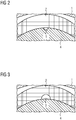
- FIG. 3 sections of different configurations of the material recess are shown.
- This rotor core 4 is located in the stator 1 and also has a permanent magnet 2 on its upper side.
- the material recess 5 designed as a groove extends from one axial end of the rotor to another axial end of the rotor and runs parallel or substantially parallel to the axis of rotation of the rotor.
- the material recess in the rotor core is centered for reasons of symmetry. An off-center design is possible.
- the material recess must not only consist of a groove, but may also consist of several successively or juxtaposed grooves.
- the material recess 5 has the shape of a semicircle for reasons of simplified manufacture of the rotor core. However, other shapes are possible.
- a rotor which comprises a rotor core 4 and a mounted on the rotor core 4 permanent magnet 2.
- the permanent magnet 2 has a material recess 3.
- the rotor is located in the stator 1.
- This embodiment is particularly advantageous because it brings a reduction in the cost of the motor with it, because the material recess 3 is located in the expensive permanent magnet 2.
- the material recess 3 is preferably designed as a groove from one axial end of the rotor to another end of the rotor centered in the permanent magnet 2 and directly adjacent to the rotor core 4th
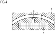
- FIG. 4 shows a section of an embodiment of a permanent magnet synchronous machine with internal permanent magnet 2, which has a material recess in the rotor core 5.
- the material recess 5 is executed on an upper side of the inner permanent magnet 2, since in addition to the reduction of the torque ripple and the Nutrastmoments an additional flux barrier for an armature transverse field is achieved.
Landscapes
- Engineering & Computer Science (AREA)
- Power Engineering (AREA)
- Permanent Field Magnets Of Synchronous Machinery (AREA)
Priority Applications (1)
| Application Number | Priority Date | Filing Date | Title |
|---|---|---|---|
| EP17167071.4A EP3393010A1 (fr) | 2017-04-19 | 2017-04-19 | Optimisation du rotor d'une machine synchrone excitée en permanence destiné à réduire l'ondulation du couple et le couple de crantage |
Applications Claiming Priority (1)
| Application Number | Priority Date | Filing Date | Title |
|---|---|---|---|
| EP17167071.4A EP3393010A1 (fr) | 2017-04-19 | 2017-04-19 | Optimisation du rotor d'une machine synchrone excitée en permanence destiné à réduire l'ondulation du couple et le couple de crantage |
Publications (1)
| Publication Number | Publication Date |
|---|---|
| EP3393010A1 true EP3393010A1 (fr) | 2018-10-24 |
Family
ID=58578904
Family Applications (1)
| Application Number | Title | Priority Date | Filing Date |
|---|---|---|---|
| EP17167071.4A Withdrawn EP3393010A1 (fr) | 2017-04-19 | 2017-04-19 | Optimisation du rotor d'une machine synchrone excitée en permanence destiné à réduire l'ondulation du couple et le couple de crantage |
Country Status (1)
| Country | Link |
|---|---|
| EP (1) | EP3393010A1 (fr) |
Citations (6)
| Publication number | Priority date | Publication date | Assignee | Title |
|---|---|---|---|---|
| JPH11308795A (ja) * | 1998-04-20 | 1999-11-05 | Mitsubishi Electric Corp | 永久磁石式同期電動機 |
| JP2000308289A (ja) * | 1999-04-19 | 2000-11-02 | Matsushita Electric Ind Co Ltd | 永久磁石形モータとその回転子の製造方法 |
| US20040041484A1 (en) * | 2002-08-28 | 2004-03-04 | Horst Gary E. | Reduced impedance interior permanent magnet machine |
| JP2005237136A (ja) * | 2004-02-20 | 2005-09-02 | Mitsubishi Electric Corp | 電動機及び密閉型圧縮機及びファンモータ |
| DE102004045939A1 (de) | 2004-09-22 | 2006-04-06 | Siemens Ag | Permanenterregte Synchronmaschine mit Unterdrückungsmitteln zur Verbesserung der Drehmomentwelligkeit |
| EP2073352A1 (fr) | 2007-12-17 | 2009-06-24 | Siemens Aktiengesellschaft | Machine synchrone à excitation permanente dotée d'aimants à coque |
-
2017
- 2017-04-19 EP EP17167071.4A patent/EP3393010A1/fr not_active Withdrawn
Patent Citations (6)
| Publication number | Priority date | Publication date | Assignee | Title |
|---|---|---|---|---|
| JPH11308795A (ja) * | 1998-04-20 | 1999-11-05 | Mitsubishi Electric Corp | 永久磁石式同期電動機 |
| JP2000308289A (ja) * | 1999-04-19 | 2000-11-02 | Matsushita Electric Ind Co Ltd | 永久磁石形モータとその回転子の製造方法 |
| US20040041484A1 (en) * | 2002-08-28 | 2004-03-04 | Horst Gary E. | Reduced impedance interior permanent magnet machine |
| JP2005237136A (ja) * | 2004-02-20 | 2005-09-02 | Mitsubishi Electric Corp | 電動機及び密閉型圧縮機及びファンモータ |
| DE102004045939A1 (de) | 2004-09-22 | 2006-04-06 | Siemens Ag | Permanenterregte Synchronmaschine mit Unterdrückungsmitteln zur Verbesserung der Drehmomentwelligkeit |
| EP2073352A1 (fr) | 2007-12-17 | 2009-06-24 | Siemens Aktiengesellschaft | Machine synchrone à excitation permanente dotée d'aimants à coque |
Similar Documents
| Publication | Publication Date | Title |
|---|---|---|
| DE102016125708A1 (de) | Motor | |
| DE102013209344A1 (de) | Magnetische barriere zum minimieren der entmagnetisierung bei synchronmaschinen mit bi- permanentmagneten | |
| DE10004175A1 (de) | Synchroner Reluktanzmotor mit Magnetflussbarriere | |
| DE102005004565A1 (de) | Stator für eine elektrische Maschine | |
| EP1064712A1 (fr) | Moteur a flux transversal polyphase | |
| DE102018210827B4 (de) | Synchronmaschine mit einem Rotor und Kraftfahrzeug | |
| DE102013213554A1 (de) | Elektrische permanentmagnet-rotationsmaschine | |
| DE112017002458T5 (de) | Verfahren zum herstellen eines läufers, verfahren zum herstellen einer dynamo-elektrischen maschine, läufer, dynamo-elektrische maschine und vorrichtung zum herstellen eines läufers | |
| DE102010032764A1 (de) | Elektrische Maschine und Stator für dieselbe | |
| EP3146619B1 (fr) | Machine électrique | |
| DE1937377B2 (de) | Stator für einen Einphaseninduktionsmotor und Verfahren zur Herstellung des Stators | |
| DE102012100332A1 (de) | Stator für eine rotierende elektrische Maschine und Verfahren zu seiner Herstellung | |
| DE112013002818T5 (de) | Stator für eine drehende elektrische Maschine und Verfahren zum Herstellen eines Stators für eine drehende elektrische Maschine | |
| WO2000003469A2 (fr) | Machine electrique, en particulier moteur a reluctance | |
| EP1955426B1 (fr) | Machine electrique et rotor pour une machine electrique | |
| DE102020101148A1 (de) | Axialflussmaschine mit radial verlaufende Blechsegmente aufweisendem Stator | |
| DE112014006365T5 (de) | Elektrische Rotationsmaschine | |
| DE102010038486A1 (de) | Wicklungen mit eckigem Querschnitt für Rotoren von elektrischen Maschinen | |
| DE112017000584T5 (de) | Rotor und Verfahren zur Auslegung des Rotors | |
| EP3171497A1 (fr) | Électromoteur cc à commutation à balais bipolaires | |
| EP3002852A1 (fr) | Rotor doté d'arêtes dépassant vers l'intérieur | |
| DE102012218506A1 (de) | Stableiterformen für elektrische Maschinen | |
| DE102012218508A1 (de) | Mehradrige Stableiter für elektrische Maschinen | |
| DE112021008135T5 (de) | Rotor und rotierende elektrische maschine | |
| DE202016107187U1 (de) | Nutrastmoment |
Legal Events
| Date | Code | Title | Description |
|---|---|---|---|
| PUAI | Public reference made under article 153(3) epc to a published international application that has entered the european phase |
Free format text: ORIGINAL CODE: 0009012 |
|
| AK | Designated contracting states |
Kind code of ref document: A1 Designated state(s): AL AT BE BG CH CY CZ DE DK EE ES FI FR GB GR HR HU IE IS IT LI LT LU LV MC MK MT NL NO PL PT RO RS SE SI SK SM TR |
|
| AX | Request for extension of the european patent |
Extension state: BA ME |
|
| STAA | Information on the status of an ep patent application or granted ep patent |
Free format text: STATUS: THE APPLICATION IS DEEMED TO BE WITHDRAWN |
|
| 18D | Application deemed to be withdrawn |
Effective date: 20190425 |