EP3393016B1 - Procédé de fabrication d'un rotor à court-circuit et rotor à court-circuit - Google Patents
Procédé de fabrication d'un rotor à court-circuit et rotor à court-circuit Download PDFInfo
- Publication number
- EP3393016B1 EP3393016B1 EP18157981.4A EP18157981A EP3393016B1 EP 3393016 B1 EP3393016 B1 EP 3393016B1 EP 18157981 A EP18157981 A EP 18157981A EP 3393016 B1 EP3393016 B1 EP 3393016B1
- Authority
- EP
- European Patent Office
- Prior art keywords
- disk
- short
- circuit
- edge
- main disk
- Prior art date
- Legal status (The legal status is an assumption and is not a legal conclusion. Google has not performed a legal analysis and makes no representation as to the accuracy of the status listed.)
- Active
Links
Images

Classifications
-
- H—ELECTRICITY
- H02—GENERATION; CONVERSION OR DISTRIBUTION OF ELECTRIC POWER
- H02K—DYNAMO-ELECTRIC MACHINES
- H02K15/00—Processes or apparatus specially adapted for manufacturing, assembling, maintaining or repairing of dynamo-electric machines
- H02K15/02—Processes or apparatus specially adapted for manufacturing, assembling, maintaining or repairing of dynamo-electric machines of stator or rotor bodies
- H02K15/021—Magnetic cores
- H02K15/023—Cage rotors
-
- B—PERFORMING OPERATIONS; TRANSPORTING
- B23—MACHINE TOOLS; METAL-WORKING NOT OTHERWISE PROVIDED FOR
- B23K—SOLDERING OR UNSOLDERING; WELDING; CLADDING OR PLATING BY SOLDERING OR WELDING; CUTTING BY APPLYING HEAT LOCALLY, e.g. FLAME CUTTING; WORKING BY LASER BEAM
- B23K26/00—Working by laser beam, e.g. welding, cutting or boring
- B23K26/20—Bonding
- B23K26/21—Bonding by welding
-
- H—ELECTRICITY
- H02—GENERATION; CONVERSION OR DISTRIBUTION OF ELECTRIC POWER
- H02K—DYNAMO-ELECTRIC MACHINES
- H02K15/00—Processes or apparatus specially adapted for manufacturing, assembling, maintaining or repairing of dynamo-electric machines
- H02K15/08—Forming windings by laying conductors into or around core parts
-
- H—ELECTRICITY
- H02—GENERATION; CONVERSION OR DISTRIBUTION OF ELECTRIC POWER
- H02K—DYNAMO-ELECTRIC MACHINES
- H02K17/00—Asynchronous induction motors; Asynchronous induction generators
- H02K17/02—Asynchronous induction motors
- H02K17/16—Asynchronous induction motors having rotors with internally short-circuited windings, e.g. cage rotors
-
- H02K17/165—
-
- H—ELECTRICITY
- H02—GENERATION; CONVERSION OR DISTRIBUTION OF ELECTRIC POWER
- H02K—DYNAMO-ELECTRIC MACHINES
- H02K17/00—Asynchronous induction motors; Asynchronous induction generators
- H02K17/02—Asynchronous induction motors
- H02K17/16—Asynchronous induction motors having rotors with internally short-circuited windings, e.g. cage rotors
- H02K17/20—Asynchronous induction motors having rotors with internally short-circuited windings, e.g. cage rotors having deep-bar rotors
-
- H—ELECTRICITY
- H02—GENERATION; CONVERSION OR DISTRIBUTION OF ELECTRIC POWER
- H02K—DYNAMO-ELECTRIC MACHINES
- H02K3/00—Details of windings
- H02K3/02—Windings characterised by the conductor material
Definitions
- the invention relates to a method for producing a short-circuit rotor and a short-circuit rotor, in particular for an asynchronous machine.
- DE 10 2013 005 050 A1 discloses a squirrel-cage rotor and a method for producing a squirrel-cage rotor, at least part of a squirrel-cage ring consisting of a disk pack, which is constructed in layers of disks with recesses through which the ends of the cage bars from the laminated rotor pass.
- the end faces of the disks of a short-circuit ring over the outer circumference have at least one bevel, which extends radially at least as far as the rod ends of the cage bars protruding from the laminated rotor core.
- a freely accessible opening between adjacent panes extends to the level of the cage bars in order to be able to join the individual parts together both electrically and mechanically.
- DE 10 2014 013 684 A1 relates to a squirrel-cage rotor for an asynchronous machine, in which several short-circuit rings attached to the end face of the laminated rotor core with recesses into which the end regions of the rotor webs protrude are provided. It is proposed that the short-circuit rings each consist of at least two metal composite disks, which consist of at least a first metal disk and a second metal disk of different material connected to it over a surface area.
- One advantage of such a configuration is the possibility of using different materials in the short-circuit rings, for example combining copper disks with alloyed copper disks (CuCrZr or similar alloys) in order to increase the speed capability and temperature resistance of the asynchronous machine.
- alloyed copper disks CuCrZr or similar alloys
- this type of alloy is heated to the welding temperature, it loses its properties in terms of strength and temperature stability in particular. Assuming a rotor with relatively thin, easy-to-manufacture individual disks, only a relatively small part of the alloyed individual disks with the originally intended properties remains after welding.
- US 2014/0339950 A1 relates to a rotor assembly with end caps to be electron beam welded. In this way, improved electrical and mechanical properties should result in a low-weight arrangement. Specifically, a single end plate with axially non-continuous grooves is described.
- the disadvantage here is that the welding process takes place directly on the rotor core and in the half-open grooves of the short-circuit disk. This creates a very high heat input into the laminated core, which can lead to insulation damage.
- the liquid weld pool can only be guided to a very limited extent and runs easily.
- DE 10 2013 202 557 A1 relates to a squirrel cage for a squirrel cage and a manufacturing method of the same. It is proposed to assemble the short-circuit rings from a connecting disk and a short-circuit disk, the connecting disk having a plurality of recesses in each of which a cage bar is arranged so that the plurality of cage bars is mechanically fixed with respect to the connecting disk.
- the short-circuit disk lies in the axial direction Direction directly on the connecting disc.
- a materially bonded connection between the cage bars and the connecting disk should be made by means of a welded connection, and a materially bonded connection between the connecting disk and the short-circuit disk by means of a soldered connection.
- WO 2015/172920 A1 discloses a method for producing a short-circuit rotor in which short-circuit rods are inserted into axial openings of a laminated core, followed by the placement and welding of a two-component short-circuit ring.
- U.S. 3,705,971 A discloses a method for producing a short-circuit rotor in which short-circuit rods are inserted into axial openings of a laminated core, followed by welding by electron beam welding of short-circuit ring and short-circuit rods.
- JP 3 480185 B2 discloses a method for producing a short-circuit rotor in which short-circuit rods are inserted into axial openings of a laminated core, followed by welding by electron beam welding of short-circuit ring and short-circuit rods.
- US 2014/132105 A1 discloses a method for manufacturing a short-circuit rotor in which short-circuit rods are inserted into axial openings of a laminated core, followed by the placement of a clamping ring around the short-circuit ring.
- the invention is therefore based on the object of specifying an improved, inexpensive and easily realizable manufacturing method and a correspondingly manufactured improved short-circuit rotor.
- a preferred development of the invention therefore provides that the short-circuit rotor is pressed axially prior to the welding of the main disk and the edge disk in such a way that the ends of the short-circuit rods abut the edge disk in a materially bonded manner.
- a tensioning device can be used to apply such an axial preload.
- the edge disk can be produced more cost-effectively, for example as a section of an, for example, extruded profile. Furthermore, the process time of cost-intensive electron beam welding is reduced to just a single circumferential weld seam.
- Another advantage is that the edge disk forms a continuous support disk without recesses for the short-circuit rods, so that the speed resistance can be increased more effectively using higher-strength materials. This is because a higher proportion of a particularly high-strength material of the edge disk remains, which leads to a higher speed stability. Furthermore, when using higher-strength disc materials, the higher-strength material and overall the properties of the material of the main disc and the peripheral disc are better preserved through only a single, radial electron beam weld seam.
- an advantageous development of the invention provides that, after welding, a clamping ring is placed around a pair of main disk and peripheral disk and tightened.
- a clamping ring can be made of steel, for example. Titanium- or nickel-based materials or a similar alloy exist and increase the torsional strength especially when both the peripheral disk and the main disk are not made of high-strength materials, but instead, for example, are both simple copper and / or aluminum disks, without high-strength alloys such as CuCrZr .
- the use of a clamping ring therefore opens up the possibility of realizing the main disk and the peripheral disk from the same, highly conductive material, while the required torsional strength is achieved via the clamping ring.
- a configuration with a main disk whose thickness, i.e. axial extent, is greater than that of the edge disk can have the advantage that the main disk forms a larger spacer from the laminated rotor core, which is less influenced by the welding.
- a thinner main disc, in particular compared to the peripheral disc has the advantage that it is easier to punch out the through openings of the main disc.
- punching out is not absolutely necessary because, for example, thicker main disks can also be produced as sections of an extruded profile by corresponding cutting to length. In practice it has been found to be beneficial proved to use a favorable manufacturing process for the main disc, therefore to choose this rather thin and thus easy to punch.
- the invention also relates to a short-circuit rotor produced by the method according to the invention, according to claim 4, having a rotor core and a short-circuit cage with short-circuit rods extending through through-openings in the rotor-core, and short-circuit rings axially short-circuiting the short-circuit rods on both sides, each short-circuit ring having a main disk with through-openings through which the short-circuit rods protruding from the laminated rotor core extend in a form-fitting manner in particular, and have an edge disk which follows the main disk axially outwards and on which the short-circuit rods are in material contact, which is characterized by the fact that the edge disk and the main disk are radially electron beam welded.
- the explanations of the manufacturing process can be applied analogously to the short-circuit rotor.
- a joining process without joining material is used, which takes place away from the laminated rotor core, so that a short-circuit rotor with significantly improved properties was manufactured in a simple manufacturing process.
- the peripheral disk and / or the main disk can preferably consist of copper and / or aluminum and / or an alloy comprising copper and / or aluminum.
- the statements regarding the manufacturing process also continue to apply here accordingly.
- a preferred embodiment provides that the edge disk consists of a higher strength material than the main disk and thus acts as a support disk.
- a particularly expedient embodiment is obtained when the short-circuit ring is radially surrounded by a clamping ring, in particular when the main disc and the peripheral disc are not made of a higher-strength alloy and / or are made of the same materials.
- this makes it possible to realize the main disk and the peripheral disk as copper and / or aluminum disks and still achieve the required torsional strength using the clamping ring.
- Fig. 1 shows essential components of one side of a short-circuit rotor 1 according to the invention in an exploded view, the axially opposite side of the short-circuit rotor 1 (not shown) being a mirror image.
- the short-circuit rotor 1 comprises a laminated rotor core 2, as is basically known in the prior art, before its components shown here are joined.
- the laminated rotor core 2 has through openings into which short-circuit rods 3 of a short-circuit cage of the short-circuit rotor 1 are already inserted here.
- the short-circuit rods 3 protrude axially, as can be seen on both sides, in order to be able to engage positively in through-openings or recesses 4 of a main disk 5.
- the axial termination of the short-circuit rotor 1 is formed by an edge disk 6, which does not have any recesses or openings for the short-circuit rods 3, since the latter are to rest firmly against it.
- the main disk 5 and the peripheral disk 6 form the short-circuit ring 7 of the short-circuit cage.
- the components shown in the exploded view are assembled axially and pressed by means of a clamping device, so that not only the main disk 5 is firmly bonded to the edge disk 6, but also the short-circuit rods 3 bonded to the Make contact with the edge disc 6.
- a radial electron beam welding takes place to join the main disk 5 to the edge disk 6.
- FIG. 2 A perspective view of the short-circuit rotor 1, which is accordingly joined in just one step, is shown Fig. 2 .
- the weld seam 8 between the main disk 5 and the edge disk 6 is also indicated there, the electron beam welding also extending to a connection between the short-circuit rods 3 and the edge disk 6.
- the main disk 5 is selected to be thinner than the peripheral disk 6, so that the through openings 4 of the main disk 5 can be punched.
- An embodiment is also conceivable in which the main disk 5 is thicker than the edge disk 6 in order to create a greater distance from the laminated core 2 during welding.
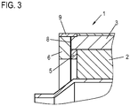
- FIG. 3 An in also extends radially around the short-circuit ring 7 Fig. 3 indicated clamping ring 9.
- the use of such a clamping ring 9 proves to be particularly advantageous when a higher torsional strength is required than is provided by the design of the disks 5, 6, for example when the disks 5, 6 both do not consist of one consist of higher-strength material, but are designed, for example, as simple copper and / or aluminum disks. After electron beam welding, the clamping ring 9 will be pulled over the short-circuit ring 7 from the main disk 5 and the peripheral disk 6.
- a short-circuit rotor according to the invention can generally be used in an asynchronous machine which also has a corresponding stator.
- the asynchronous machine can be used with particular advantage within a motor vehicle.
Landscapes
- Engineering & Computer Science (AREA)
- Power Engineering (AREA)
- Manufacturing & Machinery (AREA)
- Physics & Mathematics (AREA)
- Optics & Photonics (AREA)
- Plasma & Fusion (AREA)
- Mechanical Engineering (AREA)
- Induction Machinery (AREA)
- Manufacture Of Motors, Generators (AREA)
Claims (5)
- Procédé de fabrication d'un rotor en court-circuit (1), comprenant les étapes suivantes :- mise à disposition d'un paquet de tôles de rotor (2) avec des ouvertures de passage pour des barres de court-circuit (3) d'une cage de court-circuit ainsi que des barres de court-circuit (3),- introduction des barres de court-circuit (3) dans les ouvertures de passage de telle sorte qu'un surplomb axial subsiste sur les deux faces,- installation des deux côtés d'un disque principal (5) avec des ouvertures de passage (4) pour les barres de court-circuit (3) dont la longueur axiale correspond au surplomb, ainsi que d'un disque de bordure (6) continu se raccordant directement au disque principal (5) et aux extrémités des barres de court-circuit (3), dans lequel le disque principal (5) et le disque de bordure (6) forment une bague de court-circuit (7) de la cage de court-circuit,- soudage du disque principal (5) et du disque de bordure (6) au moyen d'un soudage à faisceaux d'électrons radial, et- pose et serrage d'une bague de serrage (9) autour d'une paire du disque principal (5) et du disque de bordure (6) après le soudage.
- Procédé selon la revendication 1,
caractérisé en ce que
le rotor en court-circuit (1) est comprimé axialement avant le soudage du disque principal (5) et du disque de bordure (6) de sorte que les extrémités des barres de court-circuit (3) s'appuient par complémentarité de matières au niveau du disque de bordure (6). - Procédé selon la revendication 1 ou 2,
caractérisé en ce que
les ouvertures de passage (4) du disque principal (5) sont découpées. - Rotor en court-circuit (1) fabriqué selon un procédé selon l'une des revendications précédentes, présentant un paquet de tôles de rotor (2) et une cage de court-circuit avec des barres de court-circuit (3) s'étendant à travers des ouvertures de passage dans le paquet de tôles de rotor (2) et les bagues de court-circuit court-circuitant axialement des deux côtés les barres de court-circuit (3), dans lequel chaque bague de court-circuit (7) présente un disque principal (5) avec des ouvertures de passage (4), à travers lesquelles les barres de court-circuit (3) saillant du paquet de tôles de rotor (2) s'étendent en particulier par complémentarité de formes, et un disque de bordure (6) suivant axialement vers l'extérieur directement le disque principal (5), disque de bordure au niveau duquel les barres de court-circuit (3) s'appuient par complémentarité de matières,
caractérisé en ce que
le disque de bordure (6) et le disque principal (5) sont soudés par faisceaux d'électrons radialement, dans lequel la bague de court-circuit (7) est entourée radialement par une bague de serrage (9). - Rotor en court-circuit (1) selon la revendication 4,
caractérisé en ce que
le disque de bordure (6) et/ou le disque principal (5) sont composés de cuivre et/ou en aluminium et/ou en alliage comprenant du cuivre et/ou de l'aluminium et/ou en ce que le disque de bordure (6) est composé d'un matériau plus résistant que le disque principal (5).
Applications Claiming Priority (1)
| Application Number | Priority Date | Filing Date | Title |
|---|---|---|---|
| DE102017206520.6A DE102017206520A1 (de) | 2017-04-18 | 2017-04-18 | Verfahren zur Herstellung eines Kurzschlussrotors und Kurzschlussrotor |
Publications (2)
| Publication Number | Publication Date |
|---|---|
| EP3393016A1 EP3393016A1 (fr) | 2018-10-24 |
| EP3393016B1 true EP3393016B1 (fr) | 2021-04-21 |
Family
ID=61256743
Family Applications (1)
| Application Number | Title | Priority Date | Filing Date |
|---|---|---|---|
| EP18157981.4A Active EP3393016B1 (fr) | 2017-04-18 | 2018-02-22 | Procédé de fabrication d'un rotor à court-circuit et rotor à court-circuit |
Country Status (4)
| Country | Link |
|---|---|
| US (1) | US10770957B2 (fr) |
| EP (1) | EP3393016B1 (fr) |
| CN (1) | CN108736670B (fr) |
| DE (1) | DE102017206520A1 (fr) |
Families Citing this family (3)
| Publication number | Priority date | Publication date | Assignee | Title |
|---|---|---|---|---|
| DE102021102296A1 (de) | 2021-02-02 | 2022-08-04 | Bayerische Motoren Werke Aktiengesellschaft | Kurzschlusskäfig für einen Rotor einer elektrischen Maschine |
| DE102023103204A1 (de) * | 2023-02-09 | 2024-08-14 | Additive | Drives GmbH | Verfahren zum Herstellen eines Läufers und/oder Rotors sowie Läufer und/oder Rotor und elektrische Maschine |
| US12567787B2 (en) * | 2023-06-29 | 2026-03-03 | Schaeffler Technologies AG & Co. KG | Electric motor rotor including end ring restrainer |
Citations (2)
| Publication number | Priority date | Publication date | Assignee | Title |
|---|---|---|---|---|
| JP3480185B2 (ja) * | 1996-07-26 | 2003-12-15 | 神鋼電機株式会社 | 高速回転するかご形誘導電動機のロータとその製造方法 |
| US20140132105A1 (en) * | 2012-11-13 | 2014-05-15 | GM Global Technology Operations LLC | Cast-in-place induction rotor end rings with improved interlocks |
Family Cites Families (17)
| Publication number | Priority date | Publication date | Assignee | Title |
|---|---|---|---|---|
| US3517238A (en) * | 1968-04-04 | 1970-06-23 | Gen Electric | Squirrel cage rotor and method of building the same |
| US3705971A (en) * | 1970-08-13 | 1972-12-12 | Gen Motors Corp | Induction motor fabrication method |
| DE102005030798A1 (de) * | 2005-06-29 | 2007-01-04 | Siemens Ag | Läufer einer Asynchronmaschine |
| JP2009017697A (ja) * | 2007-07-05 | 2009-01-22 | Toyota Industries Corp | かご型誘導電動機及びかご型誘導電動機の製造方法 |
| JP5080664B2 (ja) * | 2011-02-24 | 2012-11-21 | ファナック株式会社 | 誘導電動機のかご型ロータ |
| DE102013202404A1 (de) | 2013-02-14 | 2014-08-14 | Robert Bosch Gmbh | Kurzschlusskäfig für einen Kurzschlussläufer und Herstellungsverfahren |
| DE102013202557A1 (de) | 2013-02-18 | 2014-08-21 | Robert Bosch Gmbh | Kurzschlusskäfig für einen Kurzschlussläufer und Herstellungsverfahren desselben |
| DE102013005050A1 (de) | 2013-03-22 | 2014-09-25 | Wieland-Werke Ag | Kurzschlussläufer und dessen Einzelteile sowie Verfahren zur Herstellung eines Kurzschlussläufers |
| US20140339950A1 (en) | 2013-05-18 | 2014-11-20 | Tesla Motors, Inc. | Rotor Assembly with Electron Beam Welded End Caps |
| DE102013223054A1 (de) | 2013-11-13 | 2015-05-13 | Robert Bosch Gmbh | Rotor für eine elektrische Asynchronmaschine und Verfahren zum Fertigen desselben |
| DE102014208887A1 (de) * | 2014-05-12 | 2015-11-12 | Robert Bosch Gmbh | Mittels Reibschweißen hergestellter Käfigläuferrotor |
| DE102014013684A1 (de) | 2014-09-17 | 2016-03-17 | Wieland-Werke Ag | Kurzschlussläufer |
| DE102015223058A1 (de) * | 2015-11-23 | 2017-05-24 | Bayerische Motoren Werke Aktiengesellschaft | Käfigläufer und Verfahren für dessen Herstellung |
| DE102015224577A1 (de) * | 2015-12-08 | 2017-06-08 | Bayerische Motoren Werke Aktiengesellschaft | Rotor, Verfahren zum Herstellen eines Rotors, Asynchronmaschine und Fahrzeug |
| DE102016203143A1 (de) * | 2016-02-26 | 2017-08-31 | Robert Bosch Gmbh | Mittels Elektronenschweißen hergestellter Käfigläuferrotor |
| CN205565945U (zh) * | 2016-04-13 | 2016-09-07 | 广西恒达电机科技有限公司 | 一种防止导电排断裂的鼠笼式电机转子 |
| CN107819366A (zh) * | 2016-09-14 | 2018-03-20 | 上海蔚兰动力科技有限公司 | 感应电动机的转子及其制造方法 |
-
2017
- 2017-04-18 DE DE102017206520.6A patent/DE102017206520A1/de not_active Withdrawn
-
2018
- 2018-02-22 EP EP18157981.4A patent/EP3393016B1/fr active Active
- 2018-03-08 US US15/915,661 patent/US10770957B2/en active Active
- 2018-04-16 CN CN201810336668.1A patent/CN108736670B/zh active Active
Patent Citations (2)
| Publication number | Priority date | Publication date | Assignee | Title |
|---|---|---|---|---|
| JP3480185B2 (ja) * | 1996-07-26 | 2003-12-15 | 神鋼電機株式会社 | 高速回転するかご形誘導電動機のロータとその製造方法 |
| US20140132105A1 (en) * | 2012-11-13 | 2014-05-15 | GM Global Technology Operations LLC | Cast-in-place induction rotor end rings with improved interlocks |
Also Published As
| Publication number | Publication date |
|---|---|
| US20180301966A1 (en) | 2018-10-18 |
| EP3393016A1 (fr) | 2018-10-24 |
| US10770957B2 (en) | 2020-09-08 |
| CN108736670B (zh) | 2021-05-28 |
| DE102017206520A1 (de) | 2018-10-18 |
| CN108736670A (zh) | 2018-11-02 |
Similar Documents
| Publication | Publication Date | Title |
|---|---|---|
| EP2782222B1 (fr) | Rotor en court-circuit et procédé de fabrication d'un rotor en court-circuit | |
| EP2999101B1 (fr) | Rotor en court-circuit | |
| EP3487048A1 (fr) | Rotor à cage écureuil comprenant des anneaux de court-circuit divisés et procédé de fabrication d'un tel rotor à cage écureuil | |
| EP3008799B1 (fr) | Anneau de court-circuit pour machine électrique asynchrone composé de segments en portions d'arc de cercle | |
| WO2017089034A1 (fr) | Rotor à cage et procédé de réalisation | |
| DE10258029B4 (de) | Kurzschlußläufer | |
| EP3402057A1 (fr) | Procédé de fabrication d'un rotor à cage d'écureuil d'une machine asynchrone | |
| WO2021228493A1 (fr) | Procédé de fabrication d'un rotor et rotor | |
| DE102017215390A1 (de) | Induktionsrotor und verfahren zur montage eines induktionsrotors | |
| EP3393016A1 (fr) | Procédé de fabrication d'un rotor à court-circuit et rotor à court-circuit | |
| EP2149970B1 (fr) | Rotor pour machines asynchrones | |
| WO2019040956A1 (fr) | Composant de stator pour machine électrique | |
| EP2957026B1 (fr) | Cage en court-circuit pour moteur à rotor en court-circuit et procédé de production correspondant | |
| EP3534512B1 (fr) | Rotor en court-circuit et procédé de fabrication d'un rotor en court-circuit | |
| CH665063A5 (de) | Asynchronlaeufer. | |
| EP2957025B1 (fr) | Cage en court-circuit pour rotor en court-circuit et procédé de réalisation | |
| EP4244961B1 (fr) | Procédé de fabrication d'un rotor à cage d'écureuil doté d'un anneau de court-circuit stratifié | |
| DE19522671C2 (de) | Käfigläufer für eine Asynchronmaschine | |
| WO2016012135A1 (fr) | Bague de court-circuitage et rotor pour moteur électrique | |
| EP2870679B1 (fr) | Stator pourvu d'un noyau feuilleté entouré par une tôle d'enveloppe | |
| EP3301795A1 (fr) | Procédé de fabrication d'une bague de court-circuit | |
| WO1998001935A1 (fr) | Rotor pour moteur asynchrone, procede de fabrication dudit rotor, et moteur asynchrone | |
| EP4436015A1 (fr) | Rotor d'un moteur à cage d'écureuil, moteur à cage d'écureuil comprenant un rotor et procédé de fabrication d'un rotor d'un moteur à cage d'écureuil | |
| DE102023132269A1 (de) | Hydraulikpumpe | |
| WO2025124788A1 (fr) | Rotor pour une machine électrique, procédé de fabrication d'un rotor et machine électrique |
Legal Events
| Date | Code | Title | Description |
|---|---|---|---|
| PUAI | Public reference made under article 153(3) epc to a published international application that has entered the european phase |
Free format text: ORIGINAL CODE: 0009012 |
|
| STAA | Information on the status of an ep patent application or granted ep patent |
Free format text: STATUS: THE APPLICATION HAS BEEN PUBLISHED |
|
| AK | Designated contracting states |
Kind code of ref document: A1 Designated state(s): AL AT BE BG CH CY CZ DE DK EE ES FI FR GB GR HR HU IE IS IT LI LT LU LV MC MK MT NL NO PL PT RO RS SE SI SK SM TR |
|
| AX | Request for extension of the european patent |
Extension state: BA ME |
|
| STAA | Information on the status of an ep patent application or granted ep patent |
Free format text: STATUS: REQUEST FOR EXAMINATION WAS MADE |
|
| 17P | Request for examination filed |
Effective date: 20190424 |
|
| RBV | Designated contracting states (corrected) |
Designated state(s): AL AT BE BG CH CY CZ DE DK EE ES FI FR GB GR HR HU IE IS IT LI LT LU LV MC MK MT NL NO PL PT RO RS SE SI SK SM TR |
|
| STAA | Information on the status of an ep patent application or granted ep patent |
Free format text: STATUS: EXAMINATION IS IN PROGRESS |
|
| 17Q | First examination report despatched |
Effective date: 20191106 |
|
| GRAP | Despatch of communication of intention to grant a patent |
Free format text: ORIGINAL CODE: EPIDOSNIGR1 |
|
| STAA | Information on the status of an ep patent application or granted ep patent |
Free format text: STATUS: GRANT OF PATENT IS INTENDED |
|
| INTG | Intention to grant announced |
Effective date: 20210128 |
|
| GRAS | Grant fee paid |
Free format text: ORIGINAL CODE: EPIDOSNIGR3 |
|
| GRAA | (expected) grant |
Free format text: ORIGINAL CODE: 0009210 |
|
| STAA | Information on the status of an ep patent application or granted ep patent |
Free format text: STATUS: THE PATENT HAS BEEN GRANTED |
|
| AK | Designated contracting states |
Kind code of ref document: B1 Designated state(s): AL AT BE BG CH CY CZ DE DK EE ES FI FR GB GR HR HU IE IS IT LI LT LU LV MC MK MT NL NO PL PT RO RS SE SI SK SM TR |
|
| REG | Reference to a national code |
Ref country code: GB Ref legal event code: FG4D Free format text: NOT ENGLISH |
|
| REG | Reference to a national code |
Ref country code: CH Ref legal event code: EP |
|
| REG | Reference to a national code |
Ref country code: DE Ref legal event code: R096 Ref document number: 502018004859 Country of ref document: DE |
|
| REG | Reference to a national code |
Ref country code: IE Ref legal event code: FG4D Free format text: LANGUAGE OF EP DOCUMENT: GERMAN |
|
| REG | Reference to a national code |
Ref country code: AT Ref legal event code: REF Ref document number: 1385682 Country of ref document: AT Kind code of ref document: T Effective date: 20210515 |
|
| REG | Reference to a national code |
Ref country code: LT Ref legal event code: MG9D |
|
| REG | Reference to a national code |
Ref country code: NL Ref legal event code: MP Effective date: 20210421 |
|
| PG25 | Lapsed in a contracting state [announced via postgrant information from national office to epo] |
Ref country code: HR Free format text: LAPSE BECAUSE OF FAILURE TO SUBMIT A TRANSLATION OF THE DESCRIPTION OR TO PAY THE FEE WITHIN THE PRESCRIBED TIME-LIMIT Effective date: 20210421 Ref country code: BG Free format text: LAPSE BECAUSE OF FAILURE TO SUBMIT A TRANSLATION OF THE DESCRIPTION OR TO PAY THE FEE WITHIN THE PRESCRIBED TIME-LIMIT Effective date: 20210721 Ref country code: NL Free format text: LAPSE BECAUSE OF FAILURE TO SUBMIT A TRANSLATION OF THE DESCRIPTION OR TO PAY THE FEE WITHIN THE PRESCRIBED TIME-LIMIT Effective date: 20210421 Ref country code: FI Free format text: LAPSE BECAUSE OF FAILURE TO SUBMIT A TRANSLATION OF THE DESCRIPTION OR TO PAY THE FEE WITHIN THE PRESCRIBED TIME-LIMIT Effective date: 20210421 Ref country code: LT Free format text: LAPSE BECAUSE OF FAILURE TO SUBMIT A TRANSLATION OF THE DESCRIPTION OR TO PAY THE FEE WITHIN THE PRESCRIBED TIME-LIMIT Effective date: 20210421 |
|
| PG25 | Lapsed in a contracting state [announced via postgrant information from national office to epo] |
Ref country code: GR Free format text: LAPSE BECAUSE OF FAILURE TO SUBMIT A TRANSLATION OF THE DESCRIPTION OR TO PAY THE FEE WITHIN THE PRESCRIBED TIME-LIMIT Effective date: 20210722 Ref country code: IS Free format text: LAPSE BECAUSE OF FAILURE TO SUBMIT A TRANSLATION OF THE DESCRIPTION OR TO PAY THE FEE WITHIN THE PRESCRIBED TIME-LIMIT Effective date: 20210821 Ref country code: LV Free format text: LAPSE BECAUSE OF FAILURE TO SUBMIT A TRANSLATION OF THE DESCRIPTION OR TO PAY THE FEE WITHIN THE PRESCRIBED TIME-LIMIT Effective date: 20210421 Ref country code: PL Free format text: LAPSE BECAUSE OF FAILURE TO SUBMIT A TRANSLATION OF THE DESCRIPTION OR TO PAY THE FEE WITHIN THE PRESCRIBED TIME-LIMIT Effective date: 20210421 Ref country code: NO Free format text: LAPSE BECAUSE OF FAILURE TO SUBMIT A TRANSLATION OF THE DESCRIPTION OR TO PAY THE FEE WITHIN THE PRESCRIBED TIME-LIMIT Effective date: 20210721 Ref country code: PT Free format text: LAPSE BECAUSE OF FAILURE TO SUBMIT A TRANSLATION OF THE DESCRIPTION OR TO PAY THE FEE WITHIN THE PRESCRIBED TIME-LIMIT Effective date: 20210823 Ref country code: RS Free format text: LAPSE BECAUSE OF FAILURE TO SUBMIT A TRANSLATION OF THE DESCRIPTION OR TO PAY THE FEE WITHIN THE PRESCRIBED TIME-LIMIT Effective date: 20210421 Ref country code: SE Free format text: LAPSE BECAUSE OF FAILURE TO SUBMIT A TRANSLATION OF THE DESCRIPTION OR TO PAY THE FEE WITHIN THE PRESCRIBED TIME-LIMIT Effective date: 20210421 |
|
| REG | Reference to a national code |
Ref country code: DE Ref legal event code: R097 Ref document number: 502018004859 Country of ref document: DE |
|
| PG25 | Lapsed in a contracting state [announced via postgrant information from national office to epo] |
Ref country code: RO Free format text: LAPSE BECAUSE OF FAILURE TO SUBMIT A TRANSLATION OF THE DESCRIPTION OR TO PAY THE FEE WITHIN THE PRESCRIBED TIME-LIMIT Effective date: 20210421 Ref country code: DK Free format text: LAPSE BECAUSE OF FAILURE TO SUBMIT A TRANSLATION OF THE DESCRIPTION OR TO PAY THE FEE WITHIN THE PRESCRIBED TIME-LIMIT Effective date: 20210421 Ref country code: CZ Free format text: LAPSE BECAUSE OF FAILURE TO SUBMIT A TRANSLATION OF THE DESCRIPTION OR TO PAY THE FEE WITHIN THE PRESCRIBED TIME-LIMIT Effective date: 20210421 Ref country code: SM Free format text: LAPSE BECAUSE OF FAILURE TO SUBMIT A TRANSLATION OF THE DESCRIPTION OR TO PAY THE FEE WITHIN THE PRESCRIBED TIME-LIMIT Effective date: 20210421 Ref country code: SK Free format text: LAPSE BECAUSE OF FAILURE TO SUBMIT A TRANSLATION OF THE DESCRIPTION OR TO PAY THE FEE WITHIN THE PRESCRIBED TIME-LIMIT Effective date: 20210421 Ref country code: EE Free format text: LAPSE BECAUSE OF FAILURE TO SUBMIT A TRANSLATION OF THE DESCRIPTION OR TO PAY THE FEE WITHIN THE PRESCRIBED TIME-LIMIT Effective date: 20210421 Ref country code: ES Free format text: LAPSE BECAUSE OF FAILURE TO SUBMIT A TRANSLATION OF THE DESCRIPTION OR TO PAY THE FEE WITHIN THE PRESCRIBED TIME-LIMIT Effective date: 20210421 |
|
| PLBE | No opposition filed within time limit |
Free format text: ORIGINAL CODE: 0009261 |
|
| STAA | Information on the status of an ep patent application or granted ep patent |
Free format text: STATUS: NO OPPOSITION FILED WITHIN TIME LIMIT |
|
| 26N | No opposition filed |
Effective date: 20220124 |
|
| PG25 | Lapsed in a contracting state [announced via postgrant information from national office to epo] |
Ref country code: IS Free format text: LAPSE BECAUSE OF FAILURE TO SUBMIT A TRANSLATION OF THE DESCRIPTION OR TO PAY THE FEE WITHIN THE PRESCRIBED TIME-LIMIT Effective date: 20210821 Ref country code: AL Free format text: LAPSE BECAUSE OF FAILURE TO SUBMIT A TRANSLATION OF THE DESCRIPTION OR TO PAY THE FEE WITHIN THE PRESCRIBED TIME-LIMIT Effective date: 20210421 |
|
| PG25 | Lapsed in a contracting state [announced via postgrant information from national office to epo] |
Ref country code: IT Free format text: LAPSE BECAUSE OF FAILURE TO SUBMIT A TRANSLATION OF THE DESCRIPTION OR TO PAY THE FEE WITHIN THE PRESCRIBED TIME-LIMIT Effective date: 20210421 |
|
| PG25 | Lapsed in a contracting state [announced via postgrant information from national office to epo] |
Ref country code: MC Free format text: LAPSE BECAUSE OF FAILURE TO SUBMIT A TRANSLATION OF THE DESCRIPTION OR TO PAY THE FEE WITHIN THE PRESCRIBED TIME-LIMIT Effective date: 20210421 |
|
| REG | Reference to a national code |
Ref country code: CH Ref legal event code: PL |
|
| REG | Reference to a national code |
Ref country code: BE Ref legal event code: MM Effective date: 20220228 |
|
| GBPC | Gb: european patent ceased through non-payment of renewal fee |
Effective date: 20220222 |
|
| PG25 | Lapsed in a contracting state [announced via postgrant information from national office to epo] |
Ref country code: LU Free format text: LAPSE BECAUSE OF NON-PAYMENT OF DUE FEES Effective date: 20220222 |
|
| PG25 | Lapsed in a contracting state [announced via postgrant information from national office to epo] |
Ref country code: FR Free format text: LAPSE BECAUSE OF NON-PAYMENT OF DUE FEES Effective date: 20220228 |
|
| PG25 | Lapsed in a contracting state [announced via postgrant information from national office to epo] |
Ref country code: LI Free format text: LAPSE BECAUSE OF NON-PAYMENT OF DUE FEES Effective date: 20220228 Ref country code: IE Free format text: LAPSE BECAUSE OF NON-PAYMENT OF DUE FEES Effective date: 20220222 Ref country code: GB Free format text: LAPSE BECAUSE OF NON-PAYMENT OF DUE FEES Effective date: 20220222 Ref country code: CH Free format text: LAPSE BECAUSE OF NON-PAYMENT OF DUE FEES Effective date: 20220228 |
|
| PG25 | Lapsed in a contracting state [announced via postgrant information from national office to epo] |
Ref country code: BE Free format text: LAPSE BECAUSE OF NON-PAYMENT OF DUE FEES Effective date: 20220228 |
|
| P01 | Opt-out of the competence of the unified patent court (upc) registered |
Effective date: 20230530 |
|
| PG25 | Lapsed in a contracting state [announced via postgrant information from national office to epo] |
Ref country code: HU Free format text: LAPSE BECAUSE OF FAILURE TO SUBMIT A TRANSLATION OF THE DESCRIPTION OR TO PAY THE FEE WITHIN THE PRESCRIBED TIME-LIMIT; INVALID AB INITIO Effective date: 20180222 |
|
| REG | Reference to a national code |
Ref country code: AT Ref legal event code: MM01 Ref document number: 1385682 Country of ref document: AT Kind code of ref document: T Effective date: 20230222 |
|
| PG25 | Lapsed in a contracting state [announced via postgrant information from national office to epo] |
Ref country code: AT Free format text: LAPSE BECAUSE OF NON-PAYMENT OF DUE FEES Effective date: 20230222 |
|
| PG25 | Lapsed in a contracting state [announced via postgrant information from national office to epo] |
Ref country code: MK Free format text: LAPSE BECAUSE OF FAILURE TO SUBMIT A TRANSLATION OF THE DESCRIPTION OR TO PAY THE FEE WITHIN THE PRESCRIBED TIME-LIMIT Effective date: 20210421 Ref country code: CY Free format text: LAPSE BECAUSE OF FAILURE TO SUBMIT A TRANSLATION OF THE DESCRIPTION OR TO PAY THE FEE WITHIN THE PRESCRIBED TIME-LIMIT Effective date: 20210421 Ref country code: AT Free format text: LAPSE BECAUSE OF NON-PAYMENT OF DUE FEES Effective date: 20230222 |
|
| PG25 | Lapsed in a contracting state [announced via postgrant information from national office to epo] |
Ref country code: MT Free format text: LAPSE BECAUSE OF FAILURE TO SUBMIT A TRANSLATION OF THE DESCRIPTION OR TO PAY THE FEE WITHIN THE PRESCRIBED TIME-LIMIT Effective date: 20210421 |
|
| PG25 | Lapsed in a contracting state [announced via postgrant information from national office to epo] |
Ref country code: TR Free format text: LAPSE BECAUSE OF FAILURE TO SUBMIT A TRANSLATION OF THE DESCRIPTION OR TO PAY THE FEE WITHIN THE PRESCRIBED TIME-LIMIT Effective date: 20210421 |
|
| PGFP | Annual fee paid to national office [announced via postgrant information from national office to epo] |
Ref country code: DE Payment date: 20260228 Year of fee payment: 9 |
|
| PGFP | Annual fee paid to national office [announced via postgrant information from national office to epo] |
Ref country code: AT Payment date: 20260410 Year of fee payment: 5 |