EP3393087B1 - Adaptateur hybride ethernet sur câble coaxial fournissant un trajet d'alimentation électrique ca/cc et un trajet dvb-s/s2 sur le même câble coaxial - Google Patents
Adaptateur hybride ethernet sur câble coaxial fournissant un trajet d'alimentation électrique ca/cc et un trajet dvb-s/s2 sur le même câble coaxial Download PDFInfo
- Publication number
- EP3393087B1 EP3393087B1 EP17167364.3A EP17167364A EP3393087B1 EP 3393087 B1 EP3393087 B1 EP 3393087B1 EP 17167364 A EP17167364 A EP 17167364A EP 3393087 B1 EP3393087 B1 EP 3393087B1
- Authority
- EP
- European Patent Office
- Prior art keywords
- port
- coaxial
- transformer
- ethernet
- eoc
- Prior art date
- Legal status (The legal status is an assumption and is not a legal conclusion. Google has not performed a legal analysis and makes no representation as to the accuracy of the status listed.)
- Active
Links
Images




Classifications
-
- H—ELECTRICITY
- H04—ELECTRIC COMMUNICATION TECHNIQUE
- H04L—TRANSMISSION OF DIGITAL INFORMATION, e.g. TELEGRAPHIC COMMUNICATION
- H04L12/00—Data switching networks
- H04L12/28—Data switching networks characterised by path configuration, e.g. LAN [Local Area Networks] or WAN [Wide Area Networks]
- H04L12/2803—Home automation networks
- H04L12/2816—Controlling appliance services of a home automation network by calling their functionalities
-
- H—ELECTRICITY
- H03—ELECTRONIC CIRCUITRY
- H03H—IMPEDANCE NETWORKS, e.g. RESONANT CIRCUITS; RESONATORS
- H03H7/00—Multiple-port networks comprising only passive electrical elements as network components
- H03H7/38—Impedance-matching networks
-
- H—ELECTRICITY
- H03—ELECTRONIC CIRCUITRY
- H03H—IMPEDANCE NETWORKS, e.g. RESONANT CIRCUITS; RESONATORS
- H03H7/00—Multiple-port networks comprising only passive electrical elements as network components
- H03H7/48—Networks for connecting several sources or loads, working on the same frequency or frequency band, to a common load or source
-
- H—ELECTRICITY
- H04—ELECTRIC COMMUNICATION TECHNIQUE
- H04L—TRANSMISSION OF DIGITAL INFORMATION, e.g. TELEGRAPHIC COMMUNICATION
- H04L12/00—Data switching networks
- H04L12/28—Data switching networks characterised by path configuration, e.g. LAN [Local Area Networks] or WAN [Wide Area Networks]
- H04L12/2803—Home automation networks
- H04L12/2838—Distribution of signals within a home automation network, e.g. involving splitting/multiplexing signals to/from different paths
-
- H—ELECTRICITY
- H04—ELECTRIC COMMUNICATION TECHNIQUE
- H04L—TRANSMISSION OF DIGITAL INFORMATION, e.g. TELEGRAPHIC COMMUNICATION
- H04L69/00—Network arrangements, protocols or services independent of the application payload and not provided for in the other groups of this subclass
-
- H—ELECTRICITY
- H04—ELECTRIC COMMUNICATION TECHNIQUE
- H04N—PICTORIAL COMMUNICATION, e.g. TELEVISION
- H04N21/00—Selective content distribution, e.g. interactive television or video on demand [VOD]
- H04N21/40—Client devices specifically adapted for the reception of or interaction with content, e.g. set-top-box [STB]; Operations thereof
- H04N21/43—Processing of content or additional data, e.g. demultiplexing additional data from a digital video stream; Elementary client operations, e.g. monitoring of home network or synchronising decoder's clock; Client middleware
- H04N21/436—Interfacing a local distribution network, e.g. communicating with another STB or one or more peripheral devices inside the home
- H04N21/4363—Adapting the video stream to a specific local network, e.g. a Bluetooth® network
- H04N21/43632—Adapting the video stream to a specific local network, e.g. a Bluetooth® network involving a wired protocol, e.g. IEEE 1394
-
- H—ELECTRICITY
- H04—ELECTRIC COMMUNICATION TECHNIQUE
- H04N—PICTORIAL COMMUNICATION, e.g. TELEVISION
- H04N21/00—Selective content distribution, e.g. interactive television or video on demand [VOD]
- H04N21/60—Network structure or processes for video distribution between server and client or between remote clients; Control signalling between clients, server and network components; Transmission of management data between server and client, e.g. sending from server to client commands for recording incoming content stream; Communication details between server and client
- H04N21/61—Network physical structure; Signal processing
- H04N21/6106—Network physical structure; Signal processing specially adapted to the downstream path of the transmission network
- H04N21/6143—Network physical structure; Signal processing specially adapted to the downstream path of the transmission network involving transmission via a satellite
Definitions
- the present invention concerns the field of the passive Ethernet over coaxial adapters.
- the adapter of the invention is a hybrid passive coupler compliant with the 10Base-T or 100Base-TX Ethernet physical layer.
- the adapter according to the invention is adapted to further provide an AC/DC power supply path along with a DVB-S/S2 path on a same coaxial cable.
- LAN local area network
- 100Base-Tx 10/100 Base T
- coaxial cables installations are still common in home wiring.
- coaxial cables are widely used to bring broadband data into homes as television cables.
- a 10/100 Base T Ethernet cable uses two pairs of twisted cables for transmission/reception Tx/Rx while a coaxial cable is a unique conductive wire surrounded by an insulator and a conductive shield. Besides, the impedances of the Ethernet cable and of the coaxial cable are different and they need to be matched in order to make the data transfer possible. In order to make this connection, special circuits called hybrid transceiver or simply hybrid can be used.
- the hybrid circuit acts as a splitter, separating the transmitted signal from the received signal. Nevertheless, hybrids can be very ineffective in removing the transmitted signal from the receiving channel. As a consequence, the received signal can be heavily disturbed by the transmitted one.
- the present invention aims to address the above mentioned drawbacks by proposing a passive Ethernet over coaxial adapter which is simple to realize, inexpensive and ready to plug.
- Ethernet over coaxial adapter of the present invention can be connected directly to the Ethernet Physical transceiver and it is compliant with all the PHY Ethernet transceivers available on the market.
- the object of the present invention is an Ethernet over coaxial adapter for coupling an Ethernet transceiver to a coaxial cable, said device comprising at least:
- each port is connected through a double twisted pair.
- the transmitting port and the receiving port are directly connected to an Ethernet physical transceiver.
- the transmitting port and the receiving port can be connected to one extremity of a 10/100 Base-T Ethernet cable.
- an Rj45 connector can be used as a connector for the Ethernet cable.
- the transmitting and the receiving ports have a 100 Ohm differential impedance in the 10Base-T and 100Base-TX standards.
- the coaxial port is connected to the coaxial cable.
- an F-type connector can be used for the coaxial port.
- the coaxial port has a 75 Ohm impedance.
- the present invention uses two sets of passive elements placed in between the transmitting/receiving port of the Ethernet cable and the coaxial line to solve these two problems.
- the first set of passive elements S1 comprises at least a first transformer T1.
- the transmitting port is connected to the primary coil PL1 of the first transformer T1.
- the secondary coil comprises a central tap splitting the secondary coil in an upper USL1 and a lower secondary coil LSL1.
- the central tap CT is connected to the second set S2 of passive elements.
- the lower secondary coil LSL1 is connected to a load network or impedance matching network and the upper secondary coil ULS1 is connected to the coaxial port P2.
- a part of these elements forms an impedance matching network having a load impedance matching the impedance of the coaxial cable.
- a second set of passive components S2 an ensemble of passive elements as transformers, resistors, capacitors and inductors.
- the second set of passive element comprises at least a second transformer T2, whose primary coil is connected to the receiving path.
- the secondary coil of the second transformer is connected to the central tap of the first transformer.
- the second transformer T2 it is possible to match the impedance between the receiving port and the coaxial port in order to maximize the transmission of a signal from the coaxial cable to the receiving port.
- the use of the two sets of passive elements connected to the transmitting port, the receiving port and the coaxial port makes it possible to cancel the interferences between transmitted and received signals and to maximize the coupling between the Ethernet physical layer and the coaxial cable.
- Ethernet over coaxial adapter may include one or more additional characteristics from those listed in the following, either individually or in any technical possible combination thereof:
- Another object of the invention is a circuit providing an AC/DC power supply path comprising :
- the circuit providing an AC/DC power supply path can further provide a DVB-S/S2 path on the coaxial cable and comprises a diplexer circuit for multiplexing the Ethernet and the Dvb-S/S2 signal on the coaxial cable.
- FIG. 1 shows a schematic representation of Ethernet over Coaxial adapter EoC.
- This device will be called indifferently EoC adapter, Eoc hybrid or simply hybrid in the following.
- the EoC adapter comprises:
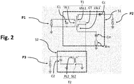
- Figure 2 shows a specific embodiment of the device of figure 1 .
- the first set of passive elements S1 comprises:
- An extremity of the upper secondary coil USL1 is connected in series to the capacitance Cc and to the coaxial port P2.
- An extremity of the lower secondary coil LSL1 is connected in series to the load network or matching impedance network comprising the matching capacitance Cm and the matching resistance Rm.
- the load network is further connected to the ground.
- the second set of passive elements S2 comprises:
- the capacitance C1 and the capacitance C2 act as a first order low-pass filter and eliminate the high frequency harmonics of the respectively transmitted and received Ethernet signal.
- the central tap point CT splitting the secondary coil of the first transformer T1 is connected to an extremity of the secondary coil SL2 of the second transformer T2.
- the other extremity of the secondary coil SL2 of the second transformer is grounded.
- the ground reference potential of the coaxial port P2 can be the same as the transceiver P1, P2 and the second transformer T2 reference potential.
- the coaxial ground is the same as the load network and the same as the secondary coil SL2 of T2 but it is different from the ground potential of the transmitting P1 and the receiving P3 port.
- This feature is normally referred as an electric isolation between electronic device - P1 and P3 ports - and the coaxial port P2.
- the transmission 100Base-TX port P1 is coupled to the top transformer T1.
- the transmitted signal is then equally split in two branches at the central tap point CT of the secondary coil of the first transformer T1.
- a first branch is the lower secondary coil LSL1 connected in series with the impedance matching network and the second branch is the upper secondary coil USL1 of the first transformer T1 connected in series with the coaxial port P2, having a coaxial load.
- the central tap CT of the first transformer is virtually at ground with respect to the signal transmitted by P1 and no signal leaks into the receiver port P3.
- the attenuation between port P1 and port P3 is maximized which avoids interferences between the transmitting and the receiving path of the Ethernet cable.
- the components of the load network are Cm is comprised in the range between 100nF and 390nF and Rm is comprised in the range between 70 and 80 Ohm in order to match the impedance of the coaxial cable, nominally equal to 75Ohm.
- Cm is comprised in the range between 100nF and 390nF
- Rm is comprised in the range between 70 and 80 Ohm in order to match the impedance of the coaxial cable, nominally equal to 75Ohm.
- Other values and impedance networks are possible.
- the coupling between the transmitting port P1 and the coaxial port P2 is then maximized and the echo is cancelled.
- part of the signal is coupled with the bottom transformer and the signal is adapted to the receiver impedance.
- the double transformer scheme of figure 2 minimizes the attenuation between the coaxial port P2, the transmission port P1 and the reception port P2. In other words, the transmission of the signal from the Ethernet cable to the coaxial cable and vice-versa is optimal.
- the transmitting port P1 and the receiving port P3 are perfectly interchangeable. In other words, the performances of the adapter according to figure 2 are exactly the same if P1 and P3 are exchanged.
- Figure 3a shows the cross port coupling as a function of the frequency.
- the curve dBS 32 represents the ratio between the power of the signal plugged on the receiving port P3 and the power of the signal emitted by the coaxial port P2 and shows an excellent coupling between these two ports. The same is true for the curve dBS 21 which is perfectly superposed to dBS 32 .
- the curve dBS 31 represents the coupling between port 3 and port 1 and is lower than -35dB, which means an excellent attenuation between these two ports. This curve is out of the scale of figure 3a .
- the graphs of figure 3a show then that the Ethernet Phy layer and the coaxial cable are well coupled, while the echo between the receiving and the transmitting path of the Ethernet Phy layer is cancelled.
- Figure 3b shows the port matching for ports P1, P2 and P3 expressed in decibel (dB).
- the graphs represent the ratio between the signal reflected by a given port and the signal coupled to the same port. The ratio is very low in the range of frequency of interest. This means that the input signals are very efficiently coupled in the Eoc hybrid.
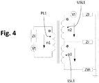
- figure 4 which shows the first transformer T1.
- Zt is the transmission impedance
- Zl is the coaxial line impedance
- Zr is the receiver impedance
- Zm is the matching network impedance
- I1 is the current in the primary coil PL1 of the first transformer T1 having n1 windings and V1 is the voltage across PL1.
- the central tap CT splits the secondary coil in the upper secondary coil USL1 having n2 windings and the lower secondary coil LSL2 having n3 windings.
- the echo cancellation is perfect if the matching impedance is equal to the coaxial cable impedance.
- the present invention uses the second transformer T2 to match impedances.
- the second transformer is used to match the impedance of the Ethernet cable and of the coaxial cable. The power of the signal transmitted between the two cables is then maximized.
- FIG. 5 shows a detailed implementation of the Eoc hybrid according to the invention.
- the blocks D and C of figure 5 represent respectively the first transformer T1 and the second transformer T2.
- the block E is the matching impedance network.
- this impedance matching network comprises a capacitor C5 in series with an impedance Z.
- the capacitor C5 can also be omitted.
- Z can comprise two resistors R1 and R2 connected in parallel.
- Z can be a simple resistor or a parallel formed by an inductor and a resistor, R//L.
- the structure of the impedance matching network and its load impedance can be adapted to coaxial line impedance.
- the coaxial line impedance can change for example based on the coaxial cable length for example if the other termination of the coaxial cable is not exactly equal to 75 Ohm.
- the transmitting port P1 and the receiving port P3 are directly connected to the Ethernet transceiver.
- the transmitting port P1 and the receiving port P3 are connected to an Rj45 connector for plugging an Ethernet cable.
- the coaxial port P3 is connected to an F-connector for plugging a coaxial cable.
- the primary coils of the two transformers comprise a central tap CTP1, CTP2.
- the purpose of these central taps CTP1 and CTP2 is to be compliant with most of the Ethernet Phys. In fact, some of them require the central tap of the magnetic to be connected to the digital supply, accordingly to the 100Base-TX application notes of the specific transceiver. This is true because we want to remove specific Ethernet magnetic using only the EoC hybrid magnetics.
- the capacitors C3 and C4 are bypass capacitors used to obtain a stable supply.
- the block A of figure 5 comprises two capacitors C1 and C2 acting as low-pass filters in the transmitting and in the receiving paths.
- capacitors remove high frequency Ethernet harmonics.
- C1 and C2 should be in the range of some pF, for example 10 pF in the example of figure 5 .
- the block F comprises an AC/DC decoupling circuit.
- This block is needed because the input impedance at the coaxial port P2 at DC without Cc would be a short circuit for any DC component available on the line.
- Such circuit is designed considering that the equivalent input impedance is an inductor in parallel with a resistor. According to the values of components in blocks C and D a capacitor of a few hundred nF should be used.
- the EoC hybrid according to the present invention works properly even if the real components, like the coaxial cable, have a mismatch between the nominal values of impedance and their real values.
- the Eoc hybrid according to the present invention offers optimal performances with an impedance mismatch as high as 5 Ohm.
- Figure 6 shows an advanced version of the circuit of figure 2 in which a termination variation TV has been added to the receiving path.
- the termination variation is a resistive termination.
- the Eoc hybrid of figure 2 has the drawback that 3.0 dB losses are included in the transmitting path and in the receiving path. As a consequence, the total nominal hybrid attenuation of 6.0 dB excluding parasitic loss.
- the circuit of figure 6 uses the second transformer T2 to provide a +3dB voltage gain in order to compensate the 3dB loss in the transmission channel P1.
- a receiving path termination of 300 Ohm is used.
- this termination variation TV allows for a more robust communication link. For example, with such a scheme it is possible to use longer cables.
- the circuit of figure 7 can be used.
- the gain in the receiving path is obtained through a fully differential amplifier AMP.
- scheme of figure 7 is compatible with any 100Base-TX Ethernet Physical layer.
- the AC power supply can support 24V AC for specific market where it is available.
- the AC power supply need to be low frequency i.e. 50 or 60Hz.
- the RJ45 block represents the connector providing the Ethernet signal through the transmitting path associated to the port P1 and the receiving path associated to the port P3.
- the Eoc hybrid can be realized according to one of the scheme according to the invention and previously presented.
- the Supply In and Supply Out are the connector providing the power supply. According an embodiment, only the Supply In or only the Supply Out connection is provided. According to another embodiment, both Supply in and Supply out are provided.
- the Bias Tee block provides the DC component to the coaxial line.
- a Bias Tee circuit is a standard three ports circuit used for setting the AC/DC bias point of a circuit.
- the Bias Tee can be properly designed to not affect the transmission of the AC components.
- circuit of figure 8 can be connected directly to the Ethernet Physical transceiver without using an RJ45 connector.
- the circuit of figure 8 can be implemented for example by using the detailed scheme of figure 9 .
- the circuit of figure 9 has its first transformer T1 connected through the central tap CT to the Bias Tee circuit BTC and the AC/DC supply port SP. Any signal present on the central tap CT is not coupled with the Ethernet receiving path.
- circuit of figure 9 eliminates the coupling between the Power Supply noise and the Ethernet receiving path.
- the block diagram of figure 8 can be implemented with the circuit represented in figure 10 .
- the Bias Tee circuit is a filter used to insert the AC/DC power supply.
- the filter is a third order T filter connected to the AC/DC supply port.
- circuit of figure 10 is completely compatible with the Eoc hybrid described in figure 2 .
- a DVB-S/S2 path on the coaxial line.
- This embodiment of the present invention can be used for example in the SmartLNB system developed by Eutelsat and described in the international patent application WO 2013/087502 A1 "Transmission/Reception of microwave signals broadcast by a satellite with an interactive return channel using a spectral broadening protocol".
- a DVB-S/S2 signal can be delivered from the outdoor unit to the indoor unit.
- This signal can coexist together with the 100Base-TX signal as they use different band.
- the 100Base-TX signal uses the band comprised between 100kHz and 125 MHz while the DVB-S/S2 signal uses the band comprised between 925 Mhz and 2175MHz.
- Figure 11 shows a block diagram for a circuit comprising an Eoc Adapter, an AC/DC power supply path SP and a DVB-S/S2 signal path over the coaxial line.
- the Ethernet signal Eth and the DVB-S/S2 signal are multiplexed using a diplexer DIP. Multiplexing the two signals means, for example, that the two signals are transmitted along the same path.
- circuit of figure 11 can be connected directly to the Ethernet Physical transceiver without using an RJ45 connector.
- Figure 12 shows the diplexer circuit used in the block diagram of figure 11 according to an embodiment of the present invention.
- the diplexer is a third order diplexer.
Landscapes
- Engineering & Computer Science (AREA)
- Automation & Control Theory (AREA)
- Computer Networks & Wireless Communication (AREA)
- Signal Processing (AREA)
- Multimedia (AREA)
- Cable Transmission Systems, Equalization Of Radio And Reduction Of Echo (AREA)
Claims (11)
- Adaptateur Ethernet sur câble coaxial (Eoc) pour coupler un émetteur-récepteur Ethernet à un câble coaxial, ledit adaptateur comprenant au moins :- un port d'émission (P1) adapté à la norme 10Base-T ou 100Base-Tx ;- un port de réception (P3) adapté à la norme 10Base-T ou 100Base-Tx ;- un port coaxial (P2) adapté pour être connecté à un câble coaxial ;- un premier ensemble de composants passifs (S1) ;- un second ensemble de composants passifs (S2) ;dans lequel :- le premier ensemble de composants passifs (S1) est connecté au port d'émission (P1), au port coaxial (P2) et au second ensemble d'éléments passifs (S2) ;- le premier ensemble de composants passifs (S1) comprend au moins un premier transformateur (T1) et un réseau d'adaptation d'impédance (Cm, Rm) ayant une impédance de charge, le premier transformateur (T1) connectant le signal depuis le port d'émission (P1) à la fois au port coaxial (P2) et au réseau d'adaptation d'impédance (Cm, Rm), l'impédance de charge s'associant à l'impédance du câble coaxial afin de minimiser le couplage entre le port d'émission (P1) et le port de réception (P3) et pour maximiser le couplage entre le port coaxial (P2) et le port d'émission (P1) ;- le second ensemble de composants passifs (S2) est connecté au moins au port coaxial (P2) par le biais du premier ensemble de composants passifs (S1) et au port de réception (P3), le second ensemble de composants passifs (S2) comprenant au moins un second transformateur (T2) adapté pour égaler l'impédance du port de réception (P3) et l'impédance du câble coaxial connecté au port coaxial (P2) afin de maximiser le couplage entre le port de réception (P3) et le port coaxial (P2) ;- le port d'émission (P1) est connecté à la bobine primaire (PL1) du premier transformateur (T1), la bobine secondaire du premier transformateur (T1) comprend une dérivation centrale (CT) divisant la bobine secondaire du premier transformateur en une bobine secondaire supérieure (USL1) et en une bobine secondaire inférieure (LSL1), la dérivation centrale (CT) est connectée au second ensemble d'éléments passifs (S2), la bobine secondaire inférieure (LSL1) est connectée au réseau d'adaptation d'impédance (Cm, Rm) et la bobine secondaire supérieure (USL1) est connectée au port coaxial (P2).
- Adaptateur Ethernet sur câble coaxial (Eoc) selon la revendication 1 caractérisé en ce que la bobine primaire (PL2) du second transformateur (T2) est connectée au port de réception (P3) et la bobine secondaire (SL2) du second transformateur (T2) est connectée à la dérivation centrale (CT) du premier transformateur (T1).
- Adaptateur Ethernet sur câble coaxial (Eoc) selon l'une des revendications précédentes caractérisé en ce que le port de réception (P3) comprend une terminaison résistive (TV).
- Adaptateur Ethernet sur câble coaxial (Eoc) selon l'une des revendications précédentes caractérisé en ce qu'il comprend un amplificateur entièrement différentiel (AMP) amplifiant le signal émis depuis le second transformateur (T2) et dirigé vers le port de réception (P3).
- Adaptateur Ethernet sur câble coaxial (Eoc) selon l'une des revendications précédentes caractérisé en ce qu'il comprend un premier condensateur (C1) connecté en parallèle au port d'émission (P1) et un second condensateur (C2) connecté en parallèle au port de réception (P3), les premier (C1) et second (C2) condensateurs servant de filtres passe-bas pour les ports d'émission et de réception.
- Adaptateur Ethernet sur câble coaxial (Eoc) selon l'une des revendications précédentes caractérisé en ce qu'il comprend un condensateur de découplage (Cc) connecté au port coaxial (P2) et au premier ensemble d'éléments passifs (S1).
- Adaptateur Ethernet sur câble coaxial (Eoc) selon l'une des revendications précédentes caractérisé en ce que le port d'émission (P1) et le port de réception (P2) sont intégrés dans un connecteur Rj45 et le port coaxial est un connecteur F.
- Adaptateur Ethernet sur câble coaxial (Eoc) selon l'une des revendications précédentes caractérisé en ce que le réseau d'adaptation d'impédance est adapté aux caractéristiques du câble coaxial.
- Adaptateur Ethernet sur câble coaxial (Eoc) selon l'une des revendications précédentes caractérisé en ce que les bobines primaires des premier (T1) et second (T2) transformateurs comprennent une première et une seconde dérivation centrale (CTP1, CTP2), au moins l'une desdites première et seconde dérivations centrales étant connectée à l'alimentation numérique de l'émetteur-récepteur Ethernet.
- Circuit fournissant un trajet d'alimentation électrique CA/CC comprenant :- l'adaptateur Ethernet sur câble coaxial (EoC) selon l'une des revendications précédentes ;- un bloc té de polarisation pour la transmission des composants CC ;- des connections d'alimentation d'entrée et/ou d'alimentation de sortie.
- Circuit selon la revendication précédente fournissant en outre une voie DVB-S/S2 sur le câble coaxial et comprenant un circuit diplexeur (DIP) pour le multiplexage de l'Ethernet et du signal Dvb-S/S2 sur le câble coaxial.
Priority Applications (2)
| Application Number | Priority Date | Filing Date | Title |
|---|---|---|---|
| EP17167364.3A EP3393087B1 (fr) | 2017-04-20 | 2017-04-20 | Adaptateur hybride ethernet sur câble coaxial fournissant un trajet d'alimentation électrique ca/cc et un trajet dvb-s/s2 sur le même câble coaxial |
| ES17167364T ES2862432T3 (es) | 2017-04-20 | 2017-04-20 | Adaptador híbrido de Ethernet sobre coaxial que proporciona una ruta de suministro de energía CA/CC y una ruta DVB-S/S2 en el mismo cable coaxial |
Applications Claiming Priority (1)
| Application Number | Priority Date | Filing Date | Title |
|---|---|---|---|
| EP17167364.3A EP3393087B1 (fr) | 2017-04-20 | 2017-04-20 | Adaptateur hybride ethernet sur câble coaxial fournissant un trajet d'alimentation électrique ca/cc et un trajet dvb-s/s2 sur le même câble coaxial |
Publications (2)
| Publication Number | Publication Date |
|---|---|
| EP3393087A1 EP3393087A1 (fr) | 2018-10-24 |
| EP3393087B1 true EP3393087B1 (fr) | 2020-11-25 |
Family
ID=58644834
Family Applications (1)
| Application Number | Title | Priority Date | Filing Date |
|---|---|---|---|
| EP17167364.3A Active EP3393087B1 (fr) | 2017-04-20 | 2017-04-20 | Adaptateur hybride ethernet sur câble coaxial fournissant un trajet d'alimentation électrique ca/cc et un trajet dvb-s/s2 sur le même câble coaxial |
Country Status (2)
| Country | Link |
|---|---|
| EP (1) | EP3393087B1 (fr) |
| ES (1) | ES2862432T3 (fr) |
Families Citing this family (1)
| Publication number | Priority date | Publication date | Assignee | Title |
|---|---|---|---|---|
| CN116781107A (zh) * | 2023-07-26 | 2023-09-19 | 裕太微(上海)电子有限公司 | 车载千兆以太网芯片适配同轴线缆传输的阻抗变换装置 |
Family Cites Families (5)
| Publication number | Priority date | Publication date | Assignee | Title |
|---|---|---|---|---|
| FI118786B (fi) * | 2004-12-23 | 2008-03-14 | Teleste Oyj | Järjestely datasignaalin välittämiseksi kaapelitelevisioverkossa |
| CN200976595Y (zh) * | 2006-11-16 | 2007-11-14 | 武汉牧马人网管科技有限公司 | 以太网络接口与同轴电缆接口的适配器 |
| FR2984641B1 (fr) | 2011-12-15 | 2014-06-13 | Eutelsat Sa | Installation d'emission/reception de signaux radioelectriques |
| US20150334186A1 (en) | 2014-05-15 | 2015-11-19 | Safeciety LLC | Coax Adaptor for Ethernet Physical Layer Transceiver |
| CN204258828U (zh) * | 2014-11-19 | 2015-04-08 | 上海龙晶科技有限公司 | 实现机顶盒与eoc模块一体化的网络接口电路 |
-
2017
- 2017-04-20 ES ES17167364T patent/ES2862432T3/es active Active
- 2017-04-20 EP EP17167364.3A patent/EP3393087B1/fr active Active
Non-Patent Citations (1)
| Title |
|---|
| None * |
Also Published As
| Publication number | Publication date |
|---|---|
| ES2862432T3 (es) | 2021-10-07 |
| EP3393087A1 (fr) | 2018-10-24 |
Similar Documents
| Publication | Publication Date | Title |
|---|---|---|
| US8810334B2 (en) | Signal splitter for use in MoCA/CATV networks | |
| US7456516B2 (en) | Power line terminating circuit and method, and power line relay device | |
| EP2617128B1 (fr) | Séparateur de signal pour réseaux moca/catv | |
| US20100246648A1 (en) | External AC-DC Coupling for Communication Interfaces | |
| US8471648B2 (en) | Signal dividing device | |
| WO2003094283A2 (fr) | Duplex integral pour la transmission de donnees de lignes de transport d'energie | |
| CN101283594A (zh) | 通过同轴电缆网络通信 | |
| EP1358762A1 (fr) | Unite d'extension coaxiale multibande pour systemes de communication numerique d'immeuble | |
| EP3393087B1 (fr) | Adaptateur hybride ethernet sur câble coaxial fournissant un trajet d'alimentation électrique ca/cc et un trajet dvb-s/s2 sur le même câble coaxial | |
| CN117639970A (zh) | 可切换式正向和反向测试点电路和射频放大器 | |
| US7841871B2 (en) | Methods and apparatus for transferring digital packet-based data | |
| US20250097001A1 (en) | Wireless over cable communication system | |
| AU675498B2 (en) | Video adapter | |
| US11949536B2 (en) | Transferring digital subscriber connection signals via a coaxial cable | |
| EP1675288B1 (fr) | Dispositif pour transmettre un signal de donnees dans un reseau de television par cable | |
| EP1973272A1 (fr) | Combinateur avec symétriseur actif pour fournir un accès Internet à large bande sur les réseaux catv | |
| MXPA96001253A (en) | Line interface apparatus and method for aislarde the line to the da terminal equipment | |
| CA2619430A1 (fr) | Coupleur de phases selectif |
Legal Events
| Date | Code | Title | Description |
|---|---|---|---|
| PUAI | Public reference made under article 153(3) epc to a published international application that has entered the european phase |
Free format text: ORIGINAL CODE: 0009012 |
|
| STAA | Information on the status of an ep patent application or granted ep patent |
Free format text: STATUS: THE APPLICATION HAS BEEN PUBLISHED |
|
| AK | Designated contracting states |
Kind code of ref document: A1 Designated state(s): AL AT BE BG CH CY CZ DE DK EE ES FI FR GB GR HR HU IE IS IT LI LT LU LV MC MK MT NL NO PL PT RO RS SE SI SK SM TR |
|
| AX | Request for extension of the european patent |
Extension state: BA ME |
|
| STAA | Information on the status of an ep patent application or granted ep patent |
Free format text: STATUS: REQUEST FOR EXAMINATION WAS MADE |
|
| 17P | Request for examination filed |
Effective date: 20190423 |
|
| RBV | Designated contracting states (corrected) |
Designated state(s): AL AT BE BG CH CY CZ DE DK EE ES FI FR GB GR HR HU IE IS IT LI LT LU LV MC MK MT NL NO PL PT RO RS SE SI SK SM TR |
|
| STAA | Information on the status of an ep patent application or granted ep patent |
Free format text: STATUS: EXAMINATION IS IN PROGRESS |
|
| 17Q | First examination report despatched |
Effective date: 20191127 |
|
| GRAP | Despatch of communication of intention to grant a patent |
Free format text: ORIGINAL CODE: EPIDOSNIGR1 |
|
| STAA | Information on the status of an ep patent application or granted ep patent |
Free format text: STATUS: GRANT OF PATENT IS INTENDED |
|
| INTG | Intention to grant announced |
Effective date: 20200214 |
|
| GRAJ | Information related to disapproval of communication of intention to grant by the applicant or resumption of examination proceedings by the epo deleted |
Free format text: ORIGINAL CODE: EPIDOSDIGR1 |
|
| STAA | Information on the status of an ep patent application or granted ep patent |
Free format text: STATUS: EXAMINATION IS IN PROGRESS |
|
| GRAP | Despatch of communication of intention to grant a patent |
Free format text: ORIGINAL CODE: EPIDOSNIGR1 |
|
| STAA | Information on the status of an ep patent application or granted ep patent |
Free format text: STATUS: GRANT OF PATENT IS INTENDED |
|
| INTC | Intention to grant announced (deleted) | ||
| INTG | Intention to grant announced |
Effective date: 20200708 |
|
| GRAS | Grant fee paid |
Free format text: ORIGINAL CODE: EPIDOSNIGR3 |
|
| GRAA | (expected) grant |
Free format text: ORIGINAL CODE: 0009210 |
|
| STAA | Information on the status of an ep patent application or granted ep patent |
Free format text: STATUS: THE PATENT HAS BEEN GRANTED |
|
| AK | Designated contracting states |
Kind code of ref document: B1 Designated state(s): AL AT BE BG CH CY CZ DE DK EE ES FI FR GB GR HR HU IE IS IT LI LT LU LV MC MK MT NL NO PL PT RO RS SE SI SK SM TR |
|
| REG | Reference to a national code |
Ref country code: GB Ref legal event code: FG4D |
|
| REG | Reference to a national code |
Ref country code: CH Ref legal event code: EP |
|
| REG | Reference to a national code |
Ref country code: DE Ref legal event code: R096 Ref document number: 602017028080 Country of ref document: DE |
|
| REG | Reference to a national code |
Ref country code: AT Ref legal event code: REF Ref document number: 1339546 Country of ref document: AT Kind code of ref document: T Effective date: 20201215 |
|
| REG | Reference to a national code |
Ref country code: IE Ref legal event code: FG4D |
|
| REG | Reference to a national code |
Ref country code: NL Ref legal event code: FP |
|
| REG | Reference to a national code |
Ref country code: AT Ref legal event code: MK05 Ref document number: 1339546 Country of ref document: AT Kind code of ref document: T Effective date: 20201125 |
|
| PG25 | Lapsed in a contracting state [announced via postgrant information from national office to epo] |
Ref country code: GR Free format text: LAPSE BECAUSE OF FAILURE TO SUBMIT A TRANSLATION OF THE DESCRIPTION OR TO PAY THE FEE WITHIN THE PRESCRIBED TIME-LIMIT Effective date: 20210226 Ref country code: FI Free format text: LAPSE BECAUSE OF FAILURE TO SUBMIT A TRANSLATION OF THE DESCRIPTION OR TO PAY THE FEE WITHIN THE PRESCRIBED TIME-LIMIT Effective date: 20201125 Ref country code: PT Free format text: LAPSE BECAUSE OF FAILURE TO SUBMIT A TRANSLATION OF THE DESCRIPTION OR TO PAY THE FEE WITHIN THE PRESCRIBED TIME-LIMIT Effective date: 20210325 Ref country code: RS Free format text: LAPSE BECAUSE OF FAILURE TO SUBMIT A TRANSLATION OF THE DESCRIPTION OR TO PAY THE FEE WITHIN THE PRESCRIBED TIME-LIMIT Effective date: 20201125 Ref country code: NO Free format text: LAPSE BECAUSE OF FAILURE TO SUBMIT A TRANSLATION OF THE DESCRIPTION OR TO PAY THE FEE WITHIN THE PRESCRIBED TIME-LIMIT Effective date: 20210225 |
|
| PG25 | Lapsed in a contracting state [announced via postgrant information from national office to epo] |
Ref country code: SE Free format text: LAPSE BECAUSE OF FAILURE TO SUBMIT A TRANSLATION OF THE DESCRIPTION OR TO PAY THE FEE WITHIN THE PRESCRIBED TIME-LIMIT Effective date: 20201125 Ref country code: AT Free format text: LAPSE BECAUSE OF FAILURE TO SUBMIT A TRANSLATION OF THE DESCRIPTION OR TO PAY THE FEE WITHIN THE PRESCRIBED TIME-LIMIT Effective date: 20201125 Ref country code: BG Free format text: LAPSE BECAUSE OF FAILURE TO SUBMIT A TRANSLATION OF THE DESCRIPTION OR TO PAY THE FEE WITHIN THE PRESCRIBED TIME-LIMIT Effective date: 20210225 Ref country code: IS Free format text: LAPSE BECAUSE OF FAILURE TO SUBMIT A TRANSLATION OF THE DESCRIPTION OR TO PAY THE FEE WITHIN THE PRESCRIBED TIME-LIMIT Effective date: 20210325 Ref country code: PL Free format text: LAPSE BECAUSE OF FAILURE TO SUBMIT A TRANSLATION OF THE DESCRIPTION OR TO PAY THE FEE WITHIN THE PRESCRIBED TIME-LIMIT Effective date: 20201125 Ref country code: LV Free format text: LAPSE BECAUSE OF FAILURE TO SUBMIT A TRANSLATION OF THE DESCRIPTION OR TO PAY THE FEE WITHIN THE PRESCRIBED TIME-LIMIT Effective date: 20201125 |
|
| RAP4 | Party data changed (patent owner data changed or rights of a patent transferred) |
Owner name: EUTELSAT SA |
|
| REG | Reference to a national code |
Ref country code: LT Ref legal event code: MG9D |
|
| PG25 | Lapsed in a contracting state [announced via postgrant information from national office to epo] |
Ref country code: HR Free format text: LAPSE BECAUSE OF FAILURE TO SUBMIT A TRANSLATION OF THE DESCRIPTION OR TO PAY THE FEE WITHIN THE PRESCRIBED TIME-LIMIT Effective date: 20201125 |
|
| PG25 | Lapsed in a contracting state [announced via postgrant information from national office to epo] |
Ref country code: CZ Free format text: LAPSE BECAUSE OF FAILURE TO SUBMIT A TRANSLATION OF THE DESCRIPTION OR TO PAY THE FEE WITHIN THE PRESCRIBED TIME-LIMIT Effective date: 20201125 Ref country code: EE Free format text: LAPSE BECAUSE OF FAILURE TO SUBMIT A TRANSLATION OF THE DESCRIPTION OR TO PAY THE FEE WITHIN THE PRESCRIBED TIME-LIMIT Effective date: 20201125 Ref country code: LT Free format text: LAPSE BECAUSE OF FAILURE TO SUBMIT A TRANSLATION OF THE DESCRIPTION OR TO PAY THE FEE WITHIN THE PRESCRIBED TIME-LIMIT Effective date: 20201125 Ref country code: SM Free format text: LAPSE BECAUSE OF FAILURE TO SUBMIT A TRANSLATION OF THE DESCRIPTION OR TO PAY THE FEE WITHIN THE PRESCRIBED TIME-LIMIT Effective date: 20201125 Ref country code: SK Free format text: LAPSE BECAUSE OF FAILURE TO SUBMIT A TRANSLATION OF THE DESCRIPTION OR TO PAY THE FEE WITHIN THE PRESCRIBED TIME-LIMIT Effective date: 20201125 Ref country code: RO Free format text: LAPSE BECAUSE OF FAILURE TO SUBMIT A TRANSLATION OF THE DESCRIPTION OR TO PAY THE FEE WITHIN THE PRESCRIBED TIME-LIMIT Effective date: 20201125 |
|
| REG | Reference to a national code |
Ref country code: DE Ref legal event code: R097 Ref document number: 602017028080 Country of ref document: DE |
|
| PG25 | Lapsed in a contracting state [announced via postgrant information from national office to epo] |
Ref country code: DK Free format text: LAPSE BECAUSE OF FAILURE TO SUBMIT A TRANSLATION OF THE DESCRIPTION OR TO PAY THE FEE WITHIN THE PRESCRIBED TIME-LIMIT Effective date: 20201125 |
|
| PLBE | No opposition filed within time limit |
Free format text: ORIGINAL CODE: 0009261 |
|
| STAA | Information on the status of an ep patent application or granted ep patent |
Free format text: STATUS: NO OPPOSITION FILED WITHIN TIME LIMIT |
|
| REG | Reference to a national code |
Ref country code: ES Ref legal event code: FG2A Ref document number: 2862432 Country of ref document: ES Kind code of ref document: T3 Effective date: 20211007 |
|
| PG25 | Lapsed in a contracting state [announced via postgrant information from national office to epo] |
Ref country code: AL Free format text: LAPSE BECAUSE OF FAILURE TO SUBMIT A TRANSLATION OF THE DESCRIPTION OR TO PAY THE FEE WITHIN THE PRESCRIBED TIME-LIMIT Effective date: 20201125 |
|
| 26N | No opposition filed |
Effective date: 20210826 |
|
| PG25 | Lapsed in a contracting state [announced via postgrant information from national office to epo] |
Ref country code: SI Free format text: LAPSE BECAUSE OF FAILURE TO SUBMIT A TRANSLATION OF THE DESCRIPTION OR TO PAY THE FEE WITHIN THE PRESCRIBED TIME-LIMIT Effective date: 20201125 Ref country code: MC Free format text: LAPSE BECAUSE OF FAILURE TO SUBMIT A TRANSLATION OF THE DESCRIPTION OR TO PAY THE FEE WITHIN THE PRESCRIBED TIME-LIMIT Effective date: 20201125 |
|
| PG25 | Lapsed in a contracting state [announced via postgrant information from national office to epo] |
Ref country code: LI Free format text: LAPSE BECAUSE OF NON-PAYMENT OF DUE FEES Effective date: 20210430 Ref country code: CH Free format text: LAPSE BECAUSE OF NON-PAYMENT OF DUE FEES Effective date: 20210430 |
|
| PG25 | Lapsed in a contracting state [announced via postgrant information from national office to epo] |
Ref country code: IE Free format text: LAPSE BECAUSE OF NON-PAYMENT OF DUE FEES Effective date: 20210420 |
|
| PG25 | Lapsed in a contracting state [announced via postgrant information from national office to epo] |
Ref country code: IS Free format text: LAPSE BECAUSE OF FAILURE TO SUBMIT A TRANSLATION OF THE DESCRIPTION OR TO PAY THE FEE WITHIN THE PRESCRIBED TIME-LIMIT Effective date: 20210325 |
|
| PG25 | Lapsed in a contracting state [announced via postgrant information from national office to epo] |
Ref country code: CY Free format text: LAPSE BECAUSE OF FAILURE TO SUBMIT A TRANSLATION OF THE DESCRIPTION OR TO PAY THE FEE WITHIN THE PRESCRIBED TIME-LIMIT Effective date: 20201125 |
|
| PG25 | Lapsed in a contracting state [announced via postgrant information from national office to epo] |
Ref country code: HU Free format text: LAPSE BECAUSE OF FAILURE TO SUBMIT A TRANSLATION OF THE DESCRIPTION OR TO PAY THE FEE WITHIN THE PRESCRIBED TIME-LIMIT; INVALID AB INITIO Effective date: 20170420 |
|
| PG25 | Lapsed in a contracting state [announced via postgrant information from national office to epo] |
Ref country code: MK Free format text: LAPSE BECAUSE OF FAILURE TO SUBMIT A TRANSLATION OF THE DESCRIPTION OR TO PAY THE FEE WITHIN THE PRESCRIBED TIME-LIMIT Effective date: 20201125 |
|
| PGFP | Annual fee paid to national office [announced via postgrant information from national office to epo] |
Ref country code: LU Payment date: 20240429 Year of fee payment: 8 |
|
| PGFP | Annual fee paid to national office [announced via postgrant information from national office to epo] |
Ref country code: NL Payment date: 20240429 Year of fee payment: 8 |
|
| PGFP | Annual fee paid to national office [announced via postgrant information from national office to epo] |
Ref country code: GB Payment date: 20240429 Year of fee payment: 8 |
|
| PGFP | Annual fee paid to national office [announced via postgrant information from national office to epo] |
Ref country code: DE Payment date: 20240530 Year of fee payment: 8 |
|
| PGFP | Annual fee paid to national office [announced via postgrant information from national office to epo] |
Ref country code: ES Payment date: 20240617 Year of fee payment: 8 |
|
| PGFP | Annual fee paid to national office [announced via postgrant information from national office to epo] |
Ref country code: IT Payment date: 20240426 Year of fee payment: 8 Ref country code: FR Payment date: 20240424 Year of fee payment: 8 |
|
| PGFP | Annual fee paid to national office [announced via postgrant information from national office to epo] |
Ref country code: BE Payment date: 20240429 Year of fee payment: 8 |
|
| PG25 | Lapsed in a contracting state [announced via postgrant information from national office to epo] |
Ref country code: MT Free format text: LAPSE BECAUSE OF FAILURE TO SUBMIT A TRANSLATION OF THE DESCRIPTION OR TO PAY THE FEE WITHIN THE PRESCRIBED TIME-LIMIT Effective date: 20201125 |
|
| REG | Reference to a national code |
Ref country code: DE Ref legal event code: R119 Ref document number: 602017028080 Country of ref document: DE |
|
| REG | Reference to a national code |
Ref country code: NL Ref legal event code: MM Effective date: 20250501 |
|
| PG25 | Lapsed in a contracting state [announced via postgrant information from national office to epo] |
Ref country code: TR Free format text: LAPSE BECAUSE OF FAILURE TO SUBMIT A TRANSLATION OF THE DESCRIPTION OR TO PAY THE FEE WITHIN THE PRESCRIBED TIME-LIMIT Effective date: 20201125 |
|
| PG25 | Lapsed in a contracting state [announced via postgrant information from national office to epo] |
Ref country code: LU Free format text: LAPSE BECAUSE OF NON-PAYMENT OF DUE FEES Effective date: 20250420 |
|
| GBPC | Gb: european patent ceased through non-payment of renewal fee |
Effective date: 20250420 |
|
| REG | Reference to a national code |
Ref country code: BE Ref legal event code: MM Effective date: 20250430 |
|
| PG25 | Lapsed in a contracting state [announced via postgrant information from national office to epo] |
Ref country code: DE Free format text: LAPSE BECAUSE OF NON-PAYMENT OF DUE FEES Effective date: 20251104 |
|
| PG25 | Lapsed in a contracting state [announced via postgrant information from national office to epo] |
Ref country code: GB Free format text: LAPSE BECAUSE OF NON-PAYMENT OF DUE FEES Effective date: 20250420 |
|
| PG25 | Lapsed in a contracting state [announced via postgrant information from national office to epo] |
Ref country code: NL Free format text: LAPSE BECAUSE OF NON-PAYMENT OF DUE FEES Effective date: 20250501 Ref country code: FR Free format text: LAPSE BECAUSE OF NON-PAYMENT OF DUE FEES Effective date: 20250430 |
|
| PG25 | Lapsed in a contracting state [announced via postgrant information from national office to epo] |
Ref country code: BE Free format text: LAPSE BECAUSE OF NON-PAYMENT OF DUE FEES Effective date: 20250430 |
|
| PG25 | Lapsed in a contracting state [announced via postgrant information from national office to epo] |
Ref country code: IT Free format text: LAPSE BECAUSE OF NON-PAYMENT OF DUE FEES Effective date: 20250420 |