EP3393406B1 - Einsatz mehrerer gallenstents - Google Patents
Einsatz mehrerer gallenstents Download PDFInfo
- Publication number
- EP3393406B1 EP3393406B1 EP16826475.2A EP16826475A EP3393406B1 EP 3393406 B1 EP3393406 B1 EP 3393406B1 EP 16826475 A EP16826475 A EP 16826475A EP 3393406 B1 EP3393406 B1 EP 3393406B1
- Authority
- EP
- European Patent Office
- Prior art keywords
- guidewire
- stent
- guide tube
- lumen
- slit
- Prior art date
- Legal status (The legal status is an assumption and is not a legal conclusion. Google has not performed a legal analysis and makes no representation as to the accuracy of the status listed.)
- Active
Links
Images



Classifications
-
- A—HUMAN NECESSITIES
- A61—MEDICAL OR VETERINARY SCIENCE; HYGIENE
- A61F—FILTERS IMPLANTABLE INTO BLOOD VESSELS; PROSTHESES; DEVICES PROVIDING PATENCY TO, OR PREVENTING COLLAPSING OF, TUBULAR STRUCTURES OF THE BODY, e.g. STENTS; ORTHOPAEDIC, NURSING OR CONTRACEPTIVE DEVICES; FOMENTATION; TREATMENT OR PROTECTION OF EYES OR EARS; BANDAGES, DRESSINGS OR ABSORBENT PADS; FIRST-AID KITS
- A61F2/00—Filters implantable into blood vessels; Prostheses, i.e. artificial substitutes or replacements for parts of the body; Appliances for connecting them with the body; Devices providing patency to, or preventing collapsing of, tubular structures of the body, e.g. stents
- A61F2/02—Prostheses implantable into the body
- A61F2/04—Hollow or tubular parts of organs, e.g. bladders, tracheae, bronchi or bile ducts
-
- A—HUMAN NECESSITIES
- A61—MEDICAL OR VETERINARY SCIENCE; HYGIENE
- A61F—FILTERS IMPLANTABLE INTO BLOOD VESSELS; PROSTHESES; DEVICES PROVIDING PATENCY TO, OR PREVENTING COLLAPSING OF, TUBULAR STRUCTURES OF THE BODY, e.g. STENTS; ORTHOPAEDIC, NURSING OR CONTRACEPTIVE DEVICES; FOMENTATION; TREATMENT OR PROTECTION OF EYES OR EARS; BANDAGES, DRESSINGS OR ABSORBENT PADS; FIRST-AID KITS
- A61F2/00—Filters implantable into blood vessels; Prostheses, i.e. artificial substitutes or replacements for parts of the body; Appliances for connecting them with the body; Devices providing patency to, or preventing collapsing of, tubular structures of the body, e.g. stents
- A61F2/82—Devices providing patency to, or preventing collapsing of, tubular structures of the body, e.g. stents
-
- A—HUMAN NECESSITIES
- A61—MEDICAL OR VETERINARY SCIENCE; HYGIENE
- A61F—FILTERS IMPLANTABLE INTO BLOOD VESSELS; PROSTHESES; DEVICES PROVIDING PATENCY TO, OR PREVENTING COLLAPSING OF, TUBULAR STRUCTURES OF THE BODY, e.g. STENTS; ORTHOPAEDIC, NURSING OR CONTRACEPTIVE DEVICES; FOMENTATION; TREATMENT OR PROTECTION OF EYES OR EARS; BANDAGES, DRESSINGS OR ABSORBENT PADS; FIRST-AID KITS
- A61F2/00—Filters implantable into blood vessels; Prostheses, i.e. artificial substitutes or replacements for parts of the body; Appliances for connecting them with the body; Devices providing patency to, or preventing collapsing of, tubular structures of the body, e.g. stents
- A61F2/95—Instruments specially adapted for placement or removal of stents or stent-grafts
-
- A—HUMAN NECESSITIES
- A61—MEDICAL OR VETERINARY SCIENCE; HYGIENE
- A61F—FILTERS IMPLANTABLE INTO BLOOD VESSELS; PROSTHESES; DEVICES PROVIDING PATENCY TO, OR PREVENTING COLLAPSING OF, TUBULAR STRUCTURES OF THE BODY, e.g. STENTS; ORTHOPAEDIC, NURSING OR CONTRACEPTIVE DEVICES; FOMENTATION; TREATMENT OR PROTECTION OF EYES OR EARS; BANDAGES, DRESSINGS OR ABSORBENT PADS; FIRST-AID KITS
- A61F2/00—Filters implantable into blood vessels; Prostheses, i.e. artificial substitutes or replacements for parts of the body; Appliances for connecting them with the body; Devices providing patency to, or preventing collapsing of, tubular structures of the body, e.g. stents
- A61F2/95—Instruments specially adapted for placement or removal of stents or stent-grafts
- A61F2/962—Instruments specially adapted for placement or removal of stents or stent-grafts having an outer sleeve
- A61F2/97—Instruments specially adapted for placement or removal of stents or stent-grafts having an outer sleeve the outer sleeve being splittable
-
- A—HUMAN NECESSITIES
- A61—MEDICAL OR VETERINARY SCIENCE; HYGIENE
- A61F—FILTERS IMPLANTABLE INTO BLOOD VESSELS; PROSTHESES; DEVICES PROVIDING PATENCY TO, OR PREVENTING COLLAPSING OF, TUBULAR STRUCTURES OF THE BODY, e.g. STENTS; ORTHOPAEDIC, NURSING OR CONTRACEPTIVE DEVICES; FOMENTATION; TREATMENT OR PROTECTION OF EYES OR EARS; BANDAGES, DRESSINGS OR ABSORBENT PADS; FIRST-AID KITS
- A61F2/00—Filters implantable into blood vessels; Prostheses, i.e. artificial substitutes or replacements for parts of the body; Appliances for connecting them with the body; Devices providing patency to, or preventing collapsing of, tubular structures of the body, e.g. stents
- A61F2/02—Prostheses implantable into the body
- A61F2/04—Hollow or tubular parts of organs, e.g. bladders, tracheae, bronchi or bile ducts
- A61F2002/041—Bile ducts
-
- A—HUMAN NECESSITIES
- A61—MEDICAL OR VETERINARY SCIENCE; HYGIENE
- A61F—FILTERS IMPLANTABLE INTO BLOOD VESSELS; PROSTHESES; DEVICES PROVIDING PATENCY TO, OR PREVENTING COLLAPSING OF, TUBULAR STRUCTURES OF THE BODY, e.g. STENTS; ORTHOPAEDIC, NURSING OR CONTRACEPTIVE DEVICES; FOMENTATION; TREATMENT OR PROTECTION OF EYES OR EARS; BANDAGES, DRESSINGS OR ABSORBENT PADS; FIRST-AID KITS
- A61F2/00—Filters implantable into blood vessels; Prostheses, i.e. artificial substitutes or replacements for parts of the body; Appliances for connecting them with the body; Devices providing patency to, or preventing collapsing of, tubular structures of the body, e.g. stents
- A61F2/02—Prostheses implantable into the body
- A61F2/04—Hollow or tubular parts of organs, e.g. bladders, tracheae, bronchi or bile ducts
- A61F2002/043—Bronchi
-
- A—HUMAN NECESSITIES
- A61—MEDICAL OR VETERINARY SCIENCE; HYGIENE
- A61F—FILTERS IMPLANTABLE INTO BLOOD VESSELS; PROSTHESES; DEVICES PROVIDING PATENCY TO, OR PREVENTING COLLAPSING OF, TUBULAR STRUCTURES OF THE BODY, e.g. STENTS; ORTHOPAEDIC, NURSING OR CONTRACEPTIVE DEVICES; FOMENTATION; TREATMENT OR PROTECTION OF EYES OR EARS; BANDAGES, DRESSINGS OR ABSORBENT PADS; FIRST-AID KITS
- A61F2/00—Filters implantable into blood vessels; Prostheses, i.e. artificial substitutes or replacements for parts of the body; Appliances for connecting them with the body; Devices providing patency to, or preventing collapsing of, tubular structures of the body, e.g. stents
- A61F2/02—Prostheses implantable into the body
- A61F2/04—Hollow or tubular parts of organs, e.g. bladders, tracheae, bronchi or bile ducts
- A61F2002/044—Oesophagi or esophagi or gullets
-
- A—HUMAN NECESSITIES
- A61—MEDICAL OR VETERINARY SCIENCE; HYGIENE
- A61F—FILTERS IMPLANTABLE INTO BLOOD VESSELS; PROSTHESES; DEVICES PROVIDING PATENCY TO, OR PREVENTING COLLAPSING OF, TUBULAR STRUCTURES OF THE BODY, e.g. STENTS; ORTHOPAEDIC, NURSING OR CONTRACEPTIVE DEVICES; FOMENTATION; TREATMENT OR PROTECTION OF EYES OR EARS; BANDAGES, DRESSINGS OR ABSORBENT PADS; FIRST-AID KITS
- A61F2/00—Filters implantable into blood vessels; Prostheses, i.e. artificial substitutes or replacements for parts of the body; Appliances for connecting them with the body; Devices providing patency to, or preventing collapsing of, tubular structures of the body, e.g. stents
- A61F2/02—Prostheses implantable into the body
- A61F2/04—Hollow or tubular parts of organs, e.g. bladders, tracheae, bronchi or bile ducts
- A61F2002/047—Urethrae
-
- A—HUMAN NECESSITIES
- A61—MEDICAL OR VETERINARY SCIENCE; HYGIENE
- A61F—FILTERS IMPLANTABLE INTO BLOOD VESSELS; PROSTHESES; DEVICES PROVIDING PATENCY TO, OR PREVENTING COLLAPSING OF, TUBULAR STRUCTURES OF THE BODY, e.g. STENTS; ORTHOPAEDIC, NURSING OR CONTRACEPTIVE DEVICES; FOMENTATION; TREATMENT OR PROTECTION OF EYES OR EARS; BANDAGES, DRESSINGS OR ABSORBENT PADS; FIRST-AID KITS
- A61F2/00—Filters implantable into blood vessels; Prostheses, i.e. artificial substitutes or replacements for parts of the body; Appliances for connecting them with the body; Devices providing patency to, or preventing collapsing of, tubular structures of the body, e.g. stents
- A61F2/82—Devices providing patency to, or preventing collapsing of, tubular structures of the body, e.g. stents
- A61F2002/826—Devices providing patency to, or preventing collapsing of, tubular structures of the body, e.g. stents more than one stent being applied sequentially
-
- A—HUMAN NECESSITIES
- A61—MEDICAL OR VETERINARY SCIENCE; HYGIENE
- A61F—FILTERS IMPLANTABLE INTO BLOOD VESSELS; PROSTHESES; DEVICES PROVIDING PATENCY TO, OR PREVENTING COLLAPSING OF, TUBULAR STRUCTURES OF THE BODY, e.g. STENTS; ORTHOPAEDIC, NURSING OR CONTRACEPTIVE DEVICES; FOMENTATION; TREATMENT OR PROTECTION OF EYES OR EARS; BANDAGES, DRESSINGS OR ABSORBENT PADS; FIRST-AID KITS
- A61F2/00—Filters implantable into blood vessels; Prostheses, i.e. artificial substitutes or replacements for parts of the body; Appliances for connecting them with the body; Devices providing patency to, or preventing collapsing of, tubular structures of the body, e.g. stents
- A61F2/95—Instruments specially adapted for placement or removal of stents or stent-grafts
- A61F2002/9505—Instruments specially adapted for placement or removal of stents or stent-grafts having retaining means other than an outer sleeve, e.g. male-female connector between stent and instrument
- A61F2002/9511—Instruments specially adapted for placement or removal of stents or stent-grafts having retaining means other than an outer sleeve, e.g. male-female connector between stent and instrument the retaining means being filaments or wires
-
- A—HUMAN NECESSITIES
- A61—MEDICAL OR VETERINARY SCIENCE; HYGIENE
- A61F—FILTERS IMPLANTABLE INTO BLOOD VESSELS; PROSTHESES; DEVICES PROVIDING PATENCY TO, OR PREVENTING COLLAPSING OF, TUBULAR STRUCTURES OF THE BODY, e.g. STENTS; ORTHOPAEDIC, NURSING OR CONTRACEPTIVE DEVICES; FOMENTATION; TREATMENT OR PROTECTION OF EYES OR EARS; BANDAGES, DRESSINGS OR ABSORBENT PADS; FIRST-AID KITS
- A61F2230/00—Geometry of prostheses classified in groups A61F2/00 - A61F2/26 or A61F2/82 or A61F9/00 or A61F11/00 or subgroups thereof
- A61F2230/0002—Two-dimensional shapes, e.g. cross-sections
- A61F2230/0004—Rounded shapes, e.g. with rounded corners
- A61F2230/001—Figure-8-shaped, e.g. hourglass-shaped
-
- A—HUMAN NECESSITIES
- A61—MEDICAL OR VETERINARY SCIENCE; HYGIENE
- A61M—DEVICES FOR INTRODUCING MEDIA INTO, OR ONTO, THE BODY; DEVICES FOR TRANSDUCING BODY MEDIA OR FOR TAKING MEDIA FROM THE BODY; DEVICES FOR PRODUCING OR ENDING SLEEP OR STUPOR
- A61M25/00—Catheters; Hollow probes
- A61M25/01—Introducing, guiding, advancing, emplacing or holding catheters
- A61M25/06—Body-piercing guide needles or the like
- A61M25/0662—Guide tubes
-
- A—HUMAN NECESSITIES
- A61—MEDICAL OR VETERINARY SCIENCE; HYGIENE
- A61M—DEVICES FOR INTRODUCING MEDIA INTO, OR ONTO, THE BODY; DEVICES FOR TRANSDUCING BODY MEDIA OR FOR TAKING MEDIA FROM THE BODY; DEVICES FOR PRODUCING OR ENDING SLEEP OR STUPOR
- A61M25/00—Catheters; Hollow probes
- A61M25/01—Introducing, guiding, advancing, emplacing or holding catheters
- A61M25/09—Guide wires
- A61M25/09041—Mechanisms for insertion of guide wires
Definitions
- Stents are typically deployed within a lumen of a body of a subject for various reasons.
- a stent is deployed within a lumen in order to widen a narrowed section of the lumen.
- insertion of a biliary stent into a bile duct is used to treat obstructions and strictures that occur in the bile duct.
- obstructions and strictures that occur in the bile duct.
- Pancreatic cancer is a common malignant cause of strictures of the bile duct.
- Noncancerous causes of bile duct stricture may include injury to the bile duct that occurs during surgery for gallbladder removal, and pancreatitis.
- a biliary stent is typically a tube-like structure that is used to support a narrowed part of the bile duct and inhibit the reformation of the stricture.
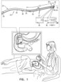
- the present detailed description begins with a description of a guide tube 22 which is used to deploy multiple stents in a lumen of the subject, in accordance with some applications of the present invention.
- Guide tube 22 is additionally shaped to define a guidewire-engaging portion 122, shown as a hole 40 through a wall 36 of guide tube 22 at distal portion 26 of the guide tube.
- Guide tube 22 is further additionally shaped to define a slit 28 extending proximally along wall 36 of guide tube 22, from distal end 32 of the guide tube.
- a proximal end 29 of slit 28 is located distally to proximal end 30 of guide tube 22.
- proximal end 29 of slit 28 is located proximally to hole 40.
- a distance D1 between a center of hole 40 and distal end 32 of guide tube 22 is at least 5 mm and/or less than 200 mm e.g., between 5 and 200 mm.
- Apparatus 20 is typically advanced into a lumen of the subject, and guide tube 22 facilitates placement of first and second stents 52 and 54 within the lumen of the subject.
- stents are described by way of illustration and not limitation.
- the scope of the present disclosure includes the use of any other drainage tube or tube-like structure configured to relieve stricture of a lumen of a subject.
- Fig. 4 is a schematic illustration of an additional configuration of guide tube 22 for deployment of first and second stents 52 and 54 in the lumen of the subject, in accordance with some applications of the present invention.
- guidewire-engaging portion 122 embodied as hole 40, is configured to engage guidewire 12 in such a way that it inhibits distal motion of first stent 52 past guidewire-engaging portion 122 of guide tube 22, due to guidewire 12 being engaged by portion 122 (e.g., disposed within hole 40).
- Guidewire-engaging portion 122 is shown in Figs. 1-3H as hole 40 by way of illustration and not limitation.
- guidewire-engaging portion 122 may be shaped to define any other configuration suitable for engaging guidewire 12 in such a manner that will grasp or otherwise hold guidewire 12 and thereby inhibit distal motion of first stent 52 past guidewire-engaging portion 122 when stent 52 is advanced distally against guidewire 12. It is noted that the techniques described herein with reference to Figs. 3A-H apply to guidewire-engaging portion 122 as shown in Fig. 4 as well.
- edges 27 of slit 28 are shaped to define guidewire-engaging portion 122.
- distance D2 between a first one of the slit edges and a second one of the slit edges is 0.45 - 0.9 mm.
- a distance D3 between slit edges 27 is smaller than distance D2, such that, for example, D2 is 2 - 5 times larger than D3.
- distance D3 between slit edges 27 is 0.09 mm - 0.45 mm, e.g., greater than 0.15 mm and/or less than 0.4 mm.
- first stent 52 is (i) constrained from distal motion past guidewire-engaging portion 122, and (ii) constrained from proximal motion past proximal end 29 of the slit 28.
- first stent 52 is in a desired deployment site in the lumen of the subject, guidewire 12 is released from guidewire-engaging portion 122 by pulling guidewire 12. Removal of guidewire 12 from guidewire-engaging portion 122 typically releases first stent 52 and allows guide tube 22 to be pulled proximally in the direction indicated by arrow 15 (as shown in Fig. 3D ) until guide tube 22 is removed from stent 52, and stent 52 can be deployed in the lumen of the subject.
- guidewire-engaging portion 122 may comprise a clip or any other suitable apparatus for engagement of guidewire 12.
- apparatus 20 is configured to deploy more than two stents, e.g., three or four stents, in the lumen of the subject (configuration not shown).
- guide tube 22 is shaped to define a second guidewire-engaging portion e.g., a second hole 40, on proximal portion 24 of tube 22.
- apparatus 20 is described with reference to lumen 4 of a common bile duct by way of illustration and not limitation.
- the scope of the present disclosure includes use of apparatus 20 in any suitable lumen to deploy multiple stents in the lumen.
- techniques and apparatus described herein may be used in a urethra, and/or in a ureter, and/or in a pancreatic duct, and/or in an esophagus, and/or in a trachea of the subject. Additionally or alternatively, techniques and apparatus described herein may be used to deploy two or more prostatic stents.
- the present invention is not limited to what has been particularly shown and described hereinabove. Rather, the scope of the present invention includes both combinations and subcombinations of the various features described hereinabove, as well as variations and modifications thereof that are not in the prior art, which would occur to persons skilled in the art upon reading the foregoing description.
- the first stent is (i) constrained from distal motion past the hole when the guidewire is disposed within the hole, and (ii) constrained from proximal motion past the proximal end of the slit when the guidewire is disposed within the slit.
- the first stent is slidably advanceable off the distal end of the guide tube when the guidewire is not disposed within the hole.
- the hole is disposed at an angular offset of 90 - 180 degrees from the slit, with respect to a central longitudinal axis of the guide tube.
- the hole is disposed at an angular offset of 180 degrees from the slit, with respect to the central longitudinal axis of the guide tube.
- a distance between a center of the hole and the distal end of the guide tube is at least 5 mm.
- a distance between a center of the hole and the distal end of the guide tube is less than 200 mm.
- the first stent has a length of 5 - 15 cm.
- the slit has a length that is greater than the length of the first stent.
- the second stent has a length of 5 - 15 cm.
- the slit has a length of 5 - 15 cm.
- the slit has a length that is: (a) greater than a length of the first stent, and (b) less than a sum of the length of the first stent and a length of the second stent.
- the hole is shaped to define an elliptical hole.
- the major axis of the elliptical hole is oriented in parallel with a longitudinal axis of the guide tube.
- the elliptical hole has a major axis having a length of 5 -10 mm and a minor axis having a length of 0.5 - 1.0 mm.
- the slit defines two slit edges that are parallel to a central longitudinal axis of the guide tube, a distance between a first one of the slit edges and a second one of the slit edges being 0.45 - 0.9 mm.
- the slit defines two slit edges that are parallel to a central longitudinal axis of the guide tube, such that, were the guide tube to be viewed from the distal end of the guide tube, an angle of 10-80 degrees is formed that is defined by:
- the angle is 20-70 degrees.
- a distal end of the second stent is disposed proximally to the proximal end of the slit.
- a distal end of the second stent is disposed distally to the proximal end of the slit.
- an outer surface of the first stent is disposed against the guidewire and the second stent surrounds the guidewire.
- the apparatus further includes a third stent, proximal to the second stent and configured to be advanced into the lumen of the subject over the guidewire.
- the apparatus further includes a fourth stent, proximal to the third stent and configured to be advanced into the lumen of the subject over the guidewire.
- Guide tube 22 is additionally shaped to define a guidewire-engaging portion 122, shown as a hole 40 through a wall 36 of guide tube 22 at distal portion 26 of the guide tube.
- Guide tube 22 is further additionally shaped to define a slit 28 extending proximally along wall 36 of guide tube 22, from distal end 32 of the guide tube.
- a proximal end 29 of slit 28 is located distally to proximal end 30 of guide tube 22.
- proximal end 29 of slit 28 is located proximally to hole 40.
- hole 40 is disposed at an angular offset alpha of 90 - 180 degrees, e.g., 180 degrees, from slit 28, with respect to a central longitudinal axis A1 of the guide tube.
- a smaller angle alpha is used (e.g., an angle alpha of approximately 60 degrees is shown in Fig. 2 ).
- a "central longitudinal axis" of an elongate structure is the set of all centroids of transverse cross-sectional sections of the structure along the structure. Thus the cross-sectional sections are locally perpendicular to the central longitudinal axis, which runs along the structure. (If the structure is circular in cross-section, the centroids correspond with the centers of the circular cross-sectional sections.)
- the central longitudinal axis of a curved elongate structure is curved, rather than straight.
- hole 40 is shaped to define an elliptical hole having a major axis W1 which is typically oriented in parallel with longitudinal axis A1 of guide tube 22.
- the major axis is typically 1.5 - 4 times longer than a minor axis W2 of hole 40.
- hole 40 has major axis W1 having a length of 5 - 10 mm and minor axis W2 having a length of 0.5 - 1.0 mm.
- Slit 28 defines two slit edges 27 that are parallel to central longitudinal axis A1 of guide tube 22, typically a distance D2 between a first one of the slit edges and a second one of the slit edges being 0.45 - 0.9 mm.
- an angle theta of 10-80 degrees e.g., 20-70 degrees, is formed that is defined by: (a) a first line extending from the central longitudinal axis to a first one of the slit edges, and (b) a second line extending from the central longitudinal axis to a second one of the slit edges.
- apparatus 20 comprises guide tube 22 (as described hereinabove with reference to Fig. 1 ), and first and second stents 52 and 54 respectively.
- first and second stents 52 and 54 surround guide tube 22, second stent 54 being disposed proximally to first stent 52 and surrounding proximal portion 24 of guide tube 22.
- First stent 52 is typically disposed over guide tube 22 such that a proximal end 53 of first stent 52 is disposed distally to proximal end 29 of slit 28 of guide tube 22 while a distal end 55 of first stent 52 is disposed proximally to hole 40.
- a distal end 59 of second stent 54 is disposed proximally to proximal end 29 of slit 28.
- distal end 59 of second stent 54 is disposed distally to proximal end 29 of slit 28.
- First stent 52 is slidably advanceable off of distal end 32 of guide tube 22. Additionally, second stent 54, is also shaped and sized to be advanceable over guide tube 22, typically subsequently to advancement of first stent 52 off of distal end 32 of guide tube 22.
- first and second stents 52 and 54 each have a length L1 of 5 - 15 cm, and slit 28 also has a length L2 of 5 - 15 cm.
- slit 28 has a length that is greater than the length of first stent 52.
- slit 28 has a length that is: (a) greater than a length of first stent 52, and (b) less than a sum of the length of first stent 52 and a length of second stent 54.
- Apparatus 20 is typically advanced into a lumen of the subject, and guide tube 22 facilitates placement of first and second stents 52 and 54 within the lumen of the subject.
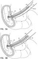
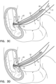
- Figs. 3A-H depict a general overview of a method for use of apparatus 20 for deploying first and second stents 52 and 54 in a lumen of a subject, in accordance with some applications of the present invention.
- stents 52 and 54 are deployed in the lumen of the subject, e.g., a common bile duct of the subject, in order to manage strictures of the lumen.
- apparatus 20 is configured such that first stent 52 is advanced into the lumen of the subject against a guidewire, and second stent 54 is advanced into the lumen over the guidewire (i.e., surrounding the guidewire).
- apparatus 20 (comprising guide tube 22 and first and second stents 52 and 54, as described hereinabove with reference to Fig. 2 ) is used in combination with a guidewire 12 to deploy stents 52 and 54 alongside each other in the lumen.
- Guidewire 12 is typically threaded through guide tube 22 such that following the threading:
- apparatus 20 is advanced into a body of the subject, e.g., into the small intestine, and into lumen 4 of the common bile duct, as shown in Fig. 3A .
- first stent 52 is advanced distally over guide tube 22 and against guidewire 12 (i.e., an outer surface of first stent 52 is disposed against guidewire 12). Due to threading of guidewire 12 as described hereinabove, stent 52 is advanced distally in lumen 4 while it is constrained from distal motion past hole 40 of guide tube 22.
- Constrained motion of stent 52 typically allows for stent 52 to be advanced to a desired deployment site within lumen 4 in a controlled manner (i.e., inhibiting uncontrolled distal motion of stent 52, thus allowing the physician to safely perform the implantation at the desired deployment site).
- first stent 52 When first stent 52 reaches a desired deployment site within lumen 4, guidewire 12 is removed from hole 40 of guide tube 22, by pulling guidewire 12 proximally in the direction indicated by arrow 11, as shown in Fig. 3B . Guidewire 12 is then typically advanced distally in lumen 4 as indicated by arrow 13 ( Fig. 3C ). Guidewire 12 is thus maintained within lumen 4 and is not removed from lumen 4 at this stage. Removal of guidewire 12 from hole 40 typically releases first stent 52 and allows for guide tube 22 to be pulled proximally in the direction indicated by arrow 15 until guide tube 22 is removed from stent 52, and stent 52 can be deployed in lumen 4 ( Fig. 3D ).
- guidewire 12 slides through slit 28 of guide tube 22 and is consequently centered within a lumen of the guide tube ( Fig. 3E ). Centering of guidewire 12 in guide tube 22 facilitates using guidewire 12 for deployment of second stent 54 within lumen 4. Positioning of guidewire 12 in guide tube 22 using slit 28 allows second stent 54 to be advanced over guidewire 12, whereas first stent 52 was advanced against (but not while around) guidewire 12.
- second stent 54 is advanced distally in lumen 4 over guide tube 22 and over guidewire 12 (which is the lumen of guide tube 22). As shown in Fig. 3G , second stent 54 continues to be distally advanced in lumen 4 (as indicted by arrows 19) until a desired deployment site is reached alongside first stent 52 ( Figs. 3F-G ). Once second stent 54 is deployed alongside first stent 52, guide tube 22 and guidewire 12 are retracted by being pulled in a proximal direction, as indicated by arrow 21 in Fig. 3H .
- first and second stents 52 and 54 are typically disposed at the same time on guide tube 22 (also as shown in Fig. 2 ) when advanced into the subject's body, to be deployed within the lumen using the techniques described herein.
- guide tube 22 also as shown in Fig. 2
- first and second stents 52 and 54 comprise self-expandable stents.
- stents are described by way of illustration and not limitation.
- the scope of the present disclosure includes the use of any other drainage tube or tube-like structure configured to relieve stricture of a lumen of a subject.
- guidewire-engaging portion 122 may be shaped to define any other configuration suitable for engaging guidewire 12 in such a manner that will grasp or otherwise hold guidewire 12 and thereby inhibit distal motion of first stent 52 past guidewire-engaging portion 122 when stent 52 is advanced distally against guidewire 12. It is noted that the techniques described herein with reference to Figs. 3A-H apply to guidewire-engaging portion 122 as shown in Fig. 4 as well.
- edges 27 of slit 28 are shaped to define guidewire-engaging portion 122.
- distance D2 between a first one of the slit edges and a second one of the slit edges is 0.45 - 0.9 mm.
- a distance D3 between slit edges 27 is smaller than distance D2, such that, for example, D2 is 2 - 5 times larger than D3.
- distance D3 between slit edges 27 is 0.09 mm - 0.45 mm, e.g., greater than 0.15 mm and/or less than 0.4 mm.
- apparatus 20 is configured to deploy more than two stents, e.g., three or four stents, in the lumen of the subject (configuration not shown).
- guide tube 22 is shaped to define a second guidewire-engaging portion e.g., a second hole 40, on proximal portion 24 of tube 22.
Landscapes
- Health & Medical Sciences (AREA)
- Engineering & Computer Science (AREA)
- Biomedical Technology (AREA)
- Cardiology (AREA)
- Oral & Maxillofacial Surgery (AREA)
- Transplantation (AREA)
- Heart & Thoracic Surgery (AREA)
- Vascular Medicine (AREA)
- Life Sciences & Earth Sciences (AREA)
- Animal Behavior & Ethology (AREA)
- General Health & Medical Sciences (AREA)
- Public Health (AREA)
- Veterinary Medicine (AREA)
- Gastroenterology & Hepatology (AREA)
- Pulmonology (AREA)
- Media Introduction/Drainage Providing Device (AREA)
Claims (5)
- Vorrichtung zur Einbringung von Stents, umfassend:einen Führungsdraht (12);einen ersten Stent (52), der (i) eine äußere Oberfläche aufweist, die nahe an dem Führungsdraht (12) angeordnet ist, und (ii) dazu konfiguriert ist, in ein Lumen eines Subjekts vorgeschoben zu werden, während die äußere Oberfläche nahe an dem Führungsdraht (12) angeordnet ist;einen zweiten Stent (54), der proximal zu dem ersten Stent (52) liegt, den Führungsdraht (12) umgibt und dazu konfiguriert ist, über den Führungsdraht (12) in das Lumen des Subjekts vorgeschoben und neben dem ersten Stent nach dem Vorschieben des ersten Stents (52) von einem distalen Ende (32) eines Führungsrohrs (22) weg platziert zu werden; unddas Führungsrohr (22), das innerhalb des ersten und des zweiten Stents (52, 54) angeordnet und mit diesen vorschiebbar ist, wobei das Führungsrohr (22) so geformt ist, dass es (a) einen Führungsdraht-Eingriffsabschnitt (122) und (b) einen Schlitz (28) definiert, der sich proximal entlang einer Wand (36) des Führungsrohrs (22) von dem distalen Ende (32) des Führungsrohrs (22) erstreckt, wobei ein proximales Ende (29) des Schlitzes (28) distal zu einem proximalen Ende (30) des Führungsrohrs (22) liegt, wobei der Führungsdraht-Eingriffsabschnitt (122) eines von einem verengten Bereich in dem Schlitz (28) und einem Loch (40) durch die Wand (36) des Führungsrohrs (22) umfasst,wobei der Führungsdraht (12) (i) in ein Lumen des Führungsrohrs (22) von einer Öffnung am distalen Ende des Führungsrohrs (22) eintritt, (ii) aus dem Lumen des Führungsrohrs (22) durch den Führungsdraht-Eingriffsabschnitt (122) des Führungsrohrs (22) gelangt und (iii) in das Lumen des Führungsrohrs (22) durch das proximale Ende (29) des Schlitzes (28) gelangt und wobei der erste Stent (52) (i) an einer distalen Bewegung über den Führungsdraht-Eingriffsabschnitt (122) hinaus gehindert wird, wenn der Führungsdraht (12) innerhalb des Führungsdraht-Eingriffsabschnitts (122) angeordnet ist, und (ii) an einer proximalen Bewegung über das proximale Ende (29) des Schlitzes (28) hinaus gehindert wird, wenn der Führungsdraht (12) innerhalb des Schlitzes (28) angeordnet ist.
- Vorrichtung nach Anspruch 1, wobei der Führungsdraht-Eingriffsabschnitt (122) einen verengten Bereich in dem Schlitz (28) umfasst.
- Vorrichtung nach Anspruch 1, wobei der Führungsdraht-Eingriffsabschnitt (122) ein Loch (40) durch die Wand (36) des Führungsrohrs (22) umfasst.
- Vorrichtung nach Anspruch 1, ferner einen dritten Stent umfassend, der proximal zu dem zweiten Stent (54) und dazu konfiguriert ist, über den Führungsdraht (12) in das Lumen des Subjekts vorgeschoben zu werden.
- Vorrichtung nach Anspruch 4, ferner einen vierten Stent umfassend, der proximal zu dem dritten Stent und dazu konfiguriert ist, über den Führungsdraht (12) in das Lumen des Subjekts vorgeschoben zu werden.
Applications Claiming Priority (2)
| Application Number | Priority Date | Filing Date | Title |
|---|---|---|---|
| GBGB1522683.0A GB201522683D0 (en) | 2015-12-22 | 2015-12-22 | Deployment of multiple biliary stents |
| PCT/IL2016/051368 WO2017109783A1 (en) | 2015-12-22 | 2016-12-22 | Deployment of multiple biliary stents |
Publications (3)
| Publication Number | Publication Date |
|---|---|
| EP3393406A1 EP3393406A1 (de) | 2018-10-31 |
| EP3393406C0 EP3393406C0 (de) | 2023-12-13 |
| EP3393406B1 true EP3393406B1 (de) | 2023-12-13 |
Family
ID=55311464
Family Applications (1)
| Application Number | Title | Priority Date | Filing Date |
|---|---|---|---|
| EP16826475.2A Active EP3393406B1 (de) | 2015-12-22 | 2016-12-22 | Einsatz mehrerer gallenstents |
Country Status (6)
| Country | Link |
|---|---|
| US (2) | US11154411B2 (de) |
| EP (1) | EP3393406B1 (de) |
| CN (2) | CN113367833A (de) |
| ES (1) | ES2965712T3 (de) |
| GB (1) | GB201522683D0 (de) |
| WO (1) | WO2017109783A1 (de) |
Families Citing this family (8)
| Publication number | Priority date | Publication date | Assignee | Title |
|---|---|---|---|---|
| WO2020003316A1 (en) * | 2018-06-28 | 2020-01-02 | Endo Gi Medical Ltd. | Deployment of multiple biliary stents |
| GB201522683D0 (en) | 2015-12-22 | 2016-02-03 | Endogi Ltd | Deployment of multiple biliary stents |
| US12186217B2 (en) | 2015-12-22 | 2025-01-07 | Endo Gi Medical Ltd. | Deployment of multiple biliary stents |
| ES3042250T3 (en) * | 2019-06-27 | 2025-11-19 | Endo Gi Medical Ltd | Assemblies for deploying biliary stents |
| US11744694B2 (en) | 2020-01-01 | 2023-09-05 | Endo Gi Medical Ltd. | Methods and assemblies for deploying biliary stents |
| US20230346582A1 (en) * | 2020-01-01 | 2023-11-02 | Endo Gi Medical Ltd. | Stent-deployment assemblies with locking mechanisms and methods of assembly |
| US20240024138A1 (en) * | 2020-01-01 | 2024-01-25 | Endo Gi Medical Ltd. | Methods and assemblies for deploying biliary stents |
| CA3257133A1 (en) * | 2022-05-13 | 2023-11-16 | Firestorm Labs, Inc. | MISSION-ADAPABLE AIR VEHICLE AND FIELD ASSEMBLY AND OPERATION PROCESSES |
Family Cites Families (39)
| Publication number | Priority date | Publication date | Assignee | Title |
|---|---|---|---|---|
| JPS62221368A (ja) | 1986-03-20 | 1987-09-29 | テルモ株式会社 | 医療器具導入用針 |
| US4883468A (en) | 1987-04-08 | 1989-11-28 | Terumo Kabushiki Kaisha | Medical tool introduction cannula and method of manufacturing the same |
| US4913141A (en) | 1988-10-25 | 1990-04-03 | Cordis Corporation | Apparatus and method for placement of a stent within a subject vessel |
| US5669924A (en) | 1995-10-26 | 1997-09-23 | Shaknovich; Alexander | Y-shuttle stent assembly for bifurcating vessels and method of using the same |
| US6346093B1 (en) | 1996-09-13 | 2002-02-12 | Scimed Life Systems, Inc. | Single operator exchange biliary catheter with common distal lumen |
| US6682536B2 (en) * | 2000-03-22 | 2004-01-27 | Advanced Stent Technologies, Inc. | Guidewire introducer sheath |
| US6299595B1 (en) | 1999-12-17 | 2001-10-09 | Advanced Cardiovascular Systems, Inc. | Catheters having rapid-exchange and over-the-wire operating modes |
| US7294146B2 (en) | 2001-12-03 | 2007-11-13 | Xtent, Inc. | Apparatus and methods for delivery of variable length stents |
| US7550002B2 (en) | 2002-04-30 | 2009-06-23 | Olympus Corporation | Stent delivery device |
| JPWO2003092782A1 (ja) | 2002-04-30 | 2005-09-08 | オリンパス株式会社 | 留置チューブガイド装置 |
| WO2005011791A2 (en) | 2003-07-31 | 2005-02-10 | Wilson-Cook Medical Inc. | Wire guide holder |
| US8211087B2 (en) | 2003-07-31 | 2012-07-03 | Cook Medical Technologies Llc | Distal wire stop |
| US20150011834A1 (en) | 2003-07-31 | 2015-01-08 | Cook Medical Technologies Llc | System and method for introducing multiple medical devices |
| AU2006335685B9 (en) | 2003-07-31 | 2012-05-03 | Cook Medical Technologies Llc | Wire guide holder with wire guide deflector |
| DE602004020901D1 (de) | 2003-07-31 | 2009-06-10 | Wilson Cook Medical Inc | System zur Einführung von mehreren Medizinprodukten |
| US20050125050A1 (en) | 2003-12-04 | 2005-06-09 | Wilson Cook Medical Incorporated | Biliary stent introducer system |
| US7323006B2 (en) * | 2004-03-30 | 2008-01-29 | Xtent, Inc. | Rapid exchange interventional devices and methods |
| US20050273150A1 (en) * | 2004-03-31 | 2005-12-08 | Howell Douglas D | Stent introducer system |
| EP1771221B1 (de) | 2004-07-29 | 2010-09-22 | Wilson-Cook Medical Inc. | Katheterschaft mit trennbarer Wand |
| US9510962B2 (en) | 2006-06-16 | 2016-12-06 | Olympus Corporation | Stent delivery system |
| US7691125B2 (en) | 2007-10-04 | 2010-04-06 | Wilson-Cook Medical Inc. | System and method for forming a stent of a desired length at an endoluminal site |
| US7963987B2 (en) | 2007-12-28 | 2011-06-21 | Cook Medical Technologies Llc | Sequential implant delivery system |
| WO2009132309A1 (en) * | 2008-04-25 | 2009-10-29 | Nellix, Inc. | Stent graft delivery system |
| AU2010223953B2 (en) | 2009-03-13 | 2014-05-01 | Bolton Medical, Inc. | System and method for deploying an endoluminal prosthesis at a surgical site |
| WO2011075509A1 (en) | 2009-12-18 | 2011-06-23 | Wilson-Cook Medical Inc. | Endoscope cap with ramp |
| US9095466B2 (en) | 2010-11-16 | 2015-08-04 | W. L. Gore & Associates, Inc. | Apposition fiber for use in endoluminal deployment of expandable devices in tortuous anatomies |
| JP5735293B2 (ja) | 2011-01-25 | 2015-06-17 | テルモ株式会社 | 生体器官病変部改善用器具 |
| EP2736580B1 (de) * | 2011-07-29 | 2019-09-18 | Boston Scientific Scimed, Inc. | Trägersystem für rx-stent |
| US9877858B2 (en) | 2011-11-14 | 2018-01-30 | W. L. Gore & Associates, Inc. | External steerable fiber for use in endoluminal deployment of expandable devices |
| US9402755B2 (en) * | 2012-03-13 | 2016-08-02 | W. L. Gore & Associates, Inc. | Sleeve retraction system |
| US8955520B2 (en) | 2012-07-19 | 2015-02-17 | Cook Medical Technologies Llc | Method of placing multiple biliary stents without re-intervention, and device for same |
| US20250127640A1 (en) | 2015-12-22 | 2025-04-24 | Endo Gi Medical Ltd. | Deployment of multiple biliary stents |
| WO2020003316A1 (en) | 2018-06-28 | 2020-01-02 | Endo Gi Medical Ltd. | Deployment of multiple biliary stents |
| GB201522683D0 (en) | 2015-12-22 | 2016-02-03 | Endogi Ltd | Deployment of multiple biliary stents |
| US12186217B2 (en) | 2015-12-22 | 2025-01-07 | Endo Gi Medical Ltd. | Deployment of multiple biliary stents |
| ES3042250T3 (en) | 2019-06-27 | 2025-11-19 | Endo Gi Medical Ltd | Assemblies for deploying biliary stents |
| US20240024138A1 (en) | 2020-01-01 | 2024-01-25 | Endo Gi Medical Ltd. | Methods and assemblies for deploying biliary stents |
| US20230346582A1 (en) | 2020-01-01 | 2023-11-02 | Endo Gi Medical Ltd. | Stent-deployment assemblies with locking mechanisms and methods of assembly |
| US11744694B2 (en) | 2020-01-01 | 2023-09-05 | Endo Gi Medical Ltd. | Methods and assemblies for deploying biliary stents |
-
2015
- 2015-12-22 GB GBGB1522683.0A patent/GB201522683D0/en not_active Ceased
-
2016
- 2016-12-22 WO PCT/IL2016/051368 patent/WO2017109783A1/en not_active Ceased
- 2016-12-22 EP EP16826475.2A patent/EP3393406B1/de active Active
- 2016-12-22 ES ES16826475T patent/ES2965712T3/es active Active
- 2016-12-22 CN CN202110661858.2A patent/CN113367833A/zh active Pending
- 2016-12-22 CN CN201680074463.XA patent/CN108366865B/zh active Active
- 2016-12-22 US US16/064,843 patent/US11154411B2/en active Active
-
2021
- 2021-09-28 US US17/449,253 patent/US12599468B2/en active Active
Also Published As
| Publication number | Publication date |
|---|---|
| WO2017109783A1 (en) | 2017-06-29 |
| GB201522683D0 (en) | 2016-02-03 |
| EP3393406C0 (de) | 2023-12-13 |
| US20190000652A1 (en) | 2019-01-03 |
| CN108366865A (zh) | 2018-08-03 |
| CN113367833A (zh) | 2021-09-10 |
| EP3393406A1 (de) | 2018-10-31 |
| ES2965712T3 (es) | 2024-04-16 |
| CN108366865B (zh) | 2021-06-25 |
| US11154411B2 (en) | 2021-10-26 |
| US12599468B2 (en) | 2026-04-14 |
| US20220008234A1 (en) | 2022-01-13 |
Similar Documents
| Publication | Publication Date | Title |
|---|---|---|
| US12599468B2 (en) | Deployment of multiple biliary stents | |
| US10195063B2 (en) | Endoprosthesis having aligned legs for ease of cannulation | |
| US10058442B2 (en) | Endoprosthesis delivery system | |
| EP3551086B1 (de) | Systeme zur ausführung der bewegung von gewebestrukturen | |
| US20110224775A1 (en) | Stent Geometry | |
| AU2020201370B2 (en) | Deployment of multiple biliary stents | |
| US11744694B2 (en) | Methods and assemblies for deploying biliary stents | |
| CN112334096B (zh) | 多个胆道支架的部署 | |
| US20240024138A1 (en) | Methods and assemblies for deploying biliary stents | |
| US20160101267A1 (en) | Anchoring Device and Methods for Use | |
| US12186217B2 (en) | Deployment of multiple biliary stents | |
| US20250127640A1 (en) | Deployment of multiple biliary stents | |
| US8257422B2 (en) | Over-the-wire detachment mechanism | |
| EP2874567A1 (de) | Nicht migrierender gallenstent | |
| US20150297875A1 (en) | Vascular dilator systems, kits, and methods | |
| JP7216578B2 (ja) | ステントデリバリーシステム | |
| US20140336464A1 (en) | Expansion devices and methods of use thereof | |
| US20230032980A1 (en) | Multistage expandable loading dilator | |
| HK1188552A (en) | Endoprosthesis delivery system | |
| HK1188552B (en) | Endoprosthesis delivery system |
Legal Events
| Date | Code | Title | Description |
|---|---|---|---|
| STAA | Information on the status of an ep patent application or granted ep patent |
Free format text: STATUS: UNKNOWN |
|
| STAA | Information on the status of an ep patent application or granted ep patent |
Free format text: STATUS: THE INTERNATIONAL PUBLICATION HAS BEEN MADE |
|
| PUAI | Public reference made under article 153(3) epc to a published international application that has entered the european phase |
Free format text: ORIGINAL CODE: 0009012 |
|
| STAA | Information on the status of an ep patent application or granted ep patent |
Free format text: STATUS: REQUEST FOR EXAMINATION WAS MADE |
|
| 17P | Request for examination filed |
Effective date: 20180718 |
|
| AK | Designated contracting states |
Kind code of ref document: A1 Designated state(s): AL AT BE BG CH CY CZ DE DK EE ES FI FR GB GR HR HU IE IS IT LI LT LU LV MC MK MT NL NO PL PT RO RS SE SI SK SM TR |
|
| AX | Request for extension of the european patent |
Extension state: BA ME |
|
| DAV | Request for validation of the european patent (deleted) | ||
| DAX | Request for extension of the european patent (deleted) | ||
| STAA | Information on the status of an ep patent application or granted ep patent |
Free format text: STATUS: EXAMINATION IS IN PROGRESS |
|
| 17Q | First examination report despatched |
Effective date: 20201217 |
|
| GRAP | Despatch of communication of intention to grant a patent |
Free format text: ORIGINAL CODE: EPIDOSNIGR1 |
|
| STAA | Information on the status of an ep patent application or granted ep patent |
Free format text: STATUS: GRANT OF PATENT IS INTENDED |
|
| INTG | Intention to grant announced |
Effective date: 20230630 |
|
| GRAS | Grant fee paid |
Free format text: ORIGINAL CODE: EPIDOSNIGR3 |
|
| GRAA | (expected) grant |
Free format text: ORIGINAL CODE: 0009210 |
|
| STAA | Information on the status of an ep patent application or granted ep patent |
Free format text: STATUS: THE PATENT HAS BEEN GRANTED |
|
| AK | Designated contracting states |
Kind code of ref document: B1 Designated state(s): AL AT BE BG CH CY CZ DE DK EE ES FI FR GB GR HR HU IE IS IT LI LT LU LV MC MK MT NL NO PL PT RO RS SE SI SK SM TR |
|
| REG | Reference to a national code |
Ref country code: GB Ref legal event code: FG4D |
|
| REG | Reference to a national code |
Ref country code: CH Ref legal event code: EP |
|
| REG | Reference to a national code |
Ref country code: DE Ref legal event code: R096 Ref document number: 602016084729 Country of ref document: DE |
|
| REG | Reference to a national code |
Ref country code: IE Ref legal event code: FG4D |
|
| U01 | Request for unitary effect filed |
Effective date: 20231220 |
|
| U07 | Unitary effect registered |
Designated state(s): AT BE BG DE DK EE FI FR IT LT LU LV MT NL PT SE SI Effective date: 20240104 |
|
| U20 | Renewal fee for the european patent with unitary effect paid |
Year of fee payment: 8 Effective date: 20231227 |
|
| PG25 | Lapsed in a contracting state [announced via postgrant information from national office to epo] |
Ref country code: GR Free format text: LAPSE BECAUSE OF FAILURE TO SUBMIT A TRANSLATION OF THE DESCRIPTION OR TO PAY THE FEE WITHIN THE PRESCRIBED TIME-LIMIT Effective date: 20240314 |
|
| REG | Reference to a national code |
Ref country code: ES Ref legal event code: FG2A Ref document number: 2965712 Country of ref document: ES Kind code of ref document: T3 Effective date: 20240416 |
|
| PG25 | Lapsed in a contracting state [announced via postgrant information from national office to epo] |
Ref country code: GR Free format text: LAPSE BECAUSE OF FAILURE TO SUBMIT A TRANSLATION OF THE DESCRIPTION OR TO PAY THE FEE WITHIN THE PRESCRIBED TIME-LIMIT Effective date: 20240314 |
|
| PG25 | Lapsed in a contracting state [announced via postgrant information from national office to epo] |
Ref country code: RS Free format text: LAPSE BECAUSE OF FAILURE TO SUBMIT A TRANSLATION OF THE DESCRIPTION OR TO PAY THE FEE WITHIN THE PRESCRIBED TIME-LIMIT Effective date: 20231213 Ref country code: NO Free format text: LAPSE BECAUSE OF FAILURE TO SUBMIT A TRANSLATION OF THE DESCRIPTION OR TO PAY THE FEE WITHIN THE PRESCRIBED TIME-LIMIT Effective date: 20240313 Ref country code: HR Free format text: LAPSE BECAUSE OF FAILURE TO SUBMIT A TRANSLATION OF THE DESCRIPTION OR TO PAY THE FEE WITHIN THE PRESCRIBED TIME-LIMIT Effective date: 20231213 |
|
| PG25 | Lapsed in a contracting state [announced via postgrant information from national office to epo] |
Ref country code: IS Free format text: LAPSE BECAUSE OF FAILURE TO SUBMIT A TRANSLATION OF THE DESCRIPTION OR TO PAY THE FEE WITHIN THE PRESCRIBED TIME-LIMIT Effective date: 20240413 |
|
| PG25 | Lapsed in a contracting state [announced via postgrant information from national office to epo] |
Ref country code: CZ Free format text: LAPSE BECAUSE OF FAILURE TO SUBMIT A TRANSLATION OF THE DESCRIPTION OR TO PAY THE FEE WITHIN THE PRESCRIBED TIME-LIMIT Effective date: 20231213 |
|
| PG25 | Lapsed in a contracting state [announced via postgrant information from national office to epo] |
Ref country code: SK Free format text: LAPSE BECAUSE OF FAILURE TO SUBMIT A TRANSLATION OF THE DESCRIPTION OR TO PAY THE FEE WITHIN THE PRESCRIBED TIME-LIMIT Effective date: 20231213 |
|
| PG25 | Lapsed in a contracting state [announced via postgrant information from national office to epo] |
Ref country code: SM Free format text: LAPSE BECAUSE OF FAILURE TO SUBMIT A TRANSLATION OF THE DESCRIPTION OR TO PAY THE FEE WITHIN THE PRESCRIBED TIME-LIMIT Effective date: 20231213 Ref country code: SK Free format text: LAPSE BECAUSE OF FAILURE TO SUBMIT A TRANSLATION OF THE DESCRIPTION OR TO PAY THE FEE WITHIN THE PRESCRIBED TIME-LIMIT Effective date: 20231213 Ref country code: RO Free format text: LAPSE BECAUSE OF FAILURE TO SUBMIT A TRANSLATION OF THE DESCRIPTION OR TO PAY THE FEE WITHIN THE PRESCRIBED TIME-LIMIT Effective date: 20231213 Ref country code: IS Free format text: LAPSE BECAUSE OF FAILURE TO SUBMIT A TRANSLATION OF THE DESCRIPTION OR TO PAY THE FEE WITHIN THE PRESCRIBED TIME-LIMIT Effective date: 20240413 Ref country code: CZ Free format text: LAPSE BECAUSE OF FAILURE TO SUBMIT A TRANSLATION OF THE DESCRIPTION OR TO PAY THE FEE WITHIN THE PRESCRIBED TIME-LIMIT Effective date: 20231213 |
|
| PG25 | Lapsed in a contracting state [announced via postgrant information from national office to epo] |
Ref country code: PL Free format text: LAPSE BECAUSE OF FAILURE TO SUBMIT A TRANSLATION OF THE DESCRIPTION OR TO PAY THE FEE WITHIN THE PRESCRIBED TIME-LIMIT Effective date: 20231213 |
|
| PG25 | Lapsed in a contracting state [announced via postgrant information from national office to epo] |
Ref country code: PL Free format text: LAPSE BECAUSE OF FAILURE TO SUBMIT A TRANSLATION OF THE DESCRIPTION OR TO PAY THE FEE WITHIN THE PRESCRIBED TIME-LIMIT Effective date: 20231213 |
|
| REG | Reference to a national code |
Ref country code: DE Ref legal event code: R097 Ref document number: 602016084729 Country of ref document: DE |
|
| PG25 | Lapsed in a contracting state [announced via postgrant information from national office to epo] |
Ref country code: MC Free format text: LAPSE BECAUSE OF FAILURE TO SUBMIT A TRANSLATION OF THE DESCRIPTION OR TO PAY THE FEE WITHIN THE PRESCRIBED TIME-LIMIT Effective date: 20231213 |
|
| PLBE | No opposition filed within time limit |
Free format text: ORIGINAL CODE: 0009261 |
|
| STAA | Information on the status of an ep patent application or granted ep patent |
Free format text: STATUS: NO OPPOSITION FILED WITHIN TIME LIMIT |
|
| 26N | No opposition filed |
Effective date: 20240916 |
|
| U20 | Renewal fee for the european patent with unitary effect paid |
Year of fee payment: 9 Effective date: 20241223 |
|
| U1N | Appointed representative for the unitary patent procedure changed after the registration of the unitary effect |
Representative=s name: HARRISON IP LIMITED; GB |
|
| PG25 | Lapsed in a contracting state [announced via postgrant information from national office to epo] |
Ref country code: CY Free format text: LAPSE BECAUSE OF FAILURE TO SUBMIT A TRANSLATION OF THE DESCRIPTION OR TO PAY THE FEE WITHIN THE PRESCRIBED TIME-LIMIT; INVALID AB INITIO Effective date: 20161222 |
|
| PG25 | Lapsed in a contracting state [announced via postgrant information from national office to epo] |
Ref country code: HU Free format text: LAPSE BECAUSE OF FAILURE TO SUBMIT A TRANSLATION OF THE DESCRIPTION OR TO PAY THE FEE WITHIN THE PRESCRIBED TIME-LIMIT; INVALID AB INITIO Effective date: 20161222 |
|
| PG25 | Lapsed in a contracting state [announced via postgrant information from national office to epo] |
Ref country code: TR Free format text: LAPSE BECAUSE OF FAILURE TO SUBMIT A TRANSLATION OF THE DESCRIPTION OR TO PAY THE FEE WITHIN THE PRESCRIBED TIME-LIMIT Effective date: 20231213 |
|
| U20 | Renewal fee for the european patent with unitary effect paid |
Year of fee payment: 10 Effective date: 20260102 |
|
| REG | Reference to a national code |
Ref country code: CH Ref legal event code: U11 Free format text: ST27 STATUS EVENT CODE: U-0-0-U10-U11 (AS PROVIDED BY THE NATIONAL OFFICE) Effective date: 20260306 |
|
| PGFP | Annual fee paid to national office [announced via postgrant information from national office to epo] |
Ref country code: GB Payment date: 20260305 Year of fee payment: 10 |
|
| PGFP | Annual fee paid to national office [announced via postgrant information from national office to epo] |
Ref country code: ES Payment date: 20260306 Year of fee payment: 10 |
|
| PGFP | Annual fee paid to national office [announced via postgrant information from national office to epo] |
Ref country code: IE Payment date: 20260305 Year of fee payment: 10 |
|
| PGFP | Annual fee paid to national office [announced via postgrant information from national office to epo] |
Ref country code: CH Payment date: 20260306 Year of fee payment: 10 |