EP3393660B1 - Verfahren zur herstellung eines versiegelten behälters - Google Patents
Verfahren zur herstellung eines versiegelten behälters Download PDFInfo
- Publication number
- EP3393660B1 EP3393660B1 EP16829418.9A EP16829418A EP3393660B1 EP 3393660 B1 EP3393660 B1 EP 3393660B1 EP 16829418 A EP16829418 A EP 16829418A EP 3393660 B1 EP3393660 B1 EP 3393660B1
- Authority
- EP
- European Patent Office
- Prior art keywords
- bag
- overmolding
- connector
- access opening
- leaktight
- Prior art date
- Legal status (The legal status is an assumption and is not a legal conclusion. Google has not performed a legal analysis and makes no representation as to the accuracy of the status listed.)
- Active
Links
Images




Classifications
-
- B—PERFORMING OPERATIONS; TRANSPORTING
- B01—PHYSICAL OR CHEMICAL PROCESSES OR APPARATUS IN GENERAL
- B01L—CHEMICAL OR PHYSICAL LABORATORY APPARATUS FOR GENERAL USE
- B01L1/00—Enclosures; Chambers
- B01L1/02—Air-pressure chambers; Air-locks therefor
-
- B—PERFORMING OPERATIONS; TRANSPORTING
- B25—HAND TOOLS; PORTABLE POWER-DRIVEN TOOLS; MANIPULATORS
- B25J—MANIPULATORS; CHAMBERS PROVIDED WITH MANIPULATION DEVICES
- B25J21/00—Chambers provided with manipulation devices
- B25J21/02—Glove-boxes, i.e. chambers in which manipulations are performed by the human hands in gloves built into the chamber walls; Gloves therefor
-
- B—PERFORMING OPERATIONS; TRANSPORTING
- B01—PHYSICAL OR CHEMICAL PROCESSES OR APPARATUS IN GENERAL
- B01L—CHEMICAL OR PHYSICAL LABORATORY APPARATUS FOR GENERAL USE
- B01L2200/00—Solutions for specific problems relating to chemical or physical laboratory apparatus
- B01L2200/02—Adapting objects or devices to another
- B01L2200/025—Align devices or objects to ensure defined positions relative to each other
-
- B—PERFORMING OPERATIONS; TRANSPORTING
- B01—PHYSICAL OR CHEMICAL PROCESSES OR APPARATUS IN GENERAL
- B01L—CHEMICAL OR PHYSICAL LABORATORY APPARATUS FOR GENERAL USE
- B01L2300/00—Additional constructional details
- B01L2300/12—Specific details about materials
- B01L2300/123—Flexible; Elastomeric
Definitions
- the invention relates to sealed containers used in sealed assemblies between a sterile enclosure such as an insulator and one or more of said containers.
- a sterile enclosure comprising a plurality of doors, and to connect containers, themselves equipped with doors, to these doors.
- the doors are opened following the connection between the sterile enclosure and the external container, to allow transfer of objects contained in the container to the sterile enclosure, or if necessary in the opposite direction.
- EP0688020A1 presents a waterproof junction device between two enclosures isolated from an external environment.
- the present invention relates to sealed containers and their manufacture for pharmaceutical or biotechnological applications requiring the limitation or avoidance of any contamination, including by particles from the external environment.
- This will typically involve obtaining a bag whose contents must be isolated from the external environment, assembled with another enclosure, such as an insulator, for sterile transfer between the bag and the enclosure.
- a typical application will be to use such a container to transfer packaging material or syringe caps sterilely from a bag in which they are initially contained and sterilized to an isolator.
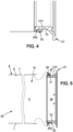
- FIG. 1 represents a waterproof container.
- Said container comprises a sealed assembly whose second access opening 20 is sealed in a sealed manner.
- the waterproof assembly comprises a pocket 1 comprising a wall 8 made of flexible film, the wall 8 of said pocket defining an interior volume V of said pocket, said pocket 1 having two opposite ends, a first access opening 10 adapted for being able to communicate the interior volume of the pocket with the exterior of the pocket at the first end, a second access opening 20 adapted to be able to communicate the interior volume of the pocket with the exterior of the pocket at the second end .
- the container also includes a connection system 9 which includes a connector 21 comprising a fixing portion 210 and an overmolding 40 overmolded on the fixing portion 210.
- the wall of the pocket is positioned opposite the overmolding at the level of the first opening of access 10, the wall of the pocket being welded to the overmolding 40.
- the second access opening 20 of said pocket 1 is closed in a watertight manner.
- Said assembly can be closed in a sealed manner at the connector 21.
- the second access opening 20 is then sealed in a sealed manner, thus forming a pocket, after in particular introducing the products into the pocket 1.
- the second access opening 20 is closed by a closing surface 2, the closing surface 2 being adapted to attach to the wall of the pocket 1 at the level of its second access opening 20 ( figure 1b ).
- each point on the circumference of the closure surface 2 is fixed at a point on the circumference of the second access opening 20 of the pocket 1, ideally bijectively.
- the second access opening 20 is closed by welding the wall of the pocket 1 onto itself at the level of its second access opening 20 ( figure 1a ). In essence all the points on the circumference of the closing surface 2 are welded together at ideally one point.
- Sterilization can for example be carried out through the wall 8 of the bag.
- Part of the wall of the pocket 1 can for example be made of Tyvec ® which is a vapor permeable material.
- the bag is then overwrapped to guarantee its sterility until use.
- sterilization can be carried out through the closing surface 2 which can for example be made of Tyvec ® .
- the connector 21 comprises a radially outer surface 22 oriented radially towards the outside of the connector 21, and the overmolding 40 comprises a radially inner surface 41 and a radially outer surface 42 opposite the radially inner surface 41 of the overmolding 40.
- the pocket 1 comprises an interior surface 6 facing the interior volume V.
- the radially exterior surface 22 of the connector 21 faces the radially interior surface 41 of the overmolding 40, such as during the positioning step of the overmolding 40 facing the wall of the pocket 1, the radially exterior surface 42 of the overmolding 40 is also facing the interior surface 6 of the pocket 1.
- the wall 8 of the pocket is made of flexible film and welded to the overmolding 40 in a continuously closed manner along the first access opening 10.
- said connector 21 comprises a radially interior surface 23 oriented radially towards the interior of the connector 21, and the overmolding 40 comprises a radially interior surface 41 and a radially exterior surface 42 opposite the radially interior surface 41 of the overmolding 40.
- the pocket 1 comprises an exterior surface 7 opposite the interior surface 6.
- the radially interior surface 23 of the connector 21 faces the radially exterior surface 42 of the overmolding 40, such as during the positioning step of the overmolding 40 facing the wall 8 of the pocket 1, the radially interior surface 41 of the overmolding 40 is also placed facing the exterior surface 7 of the wall 8 of the pocket 1.
- the passage between pocket 1 and the outside is made up of the superposition, going from the inside to the outside, of the thickness of the wall of pocket 1, of the thickness of the overmolding and the thickness of the connector 21 at its fixing portion.
- the molding element 3 is also annular such that it surrounds the thickness of the connector 21 at the level of its fixing portion 210.
- the overmolding 40 thus obtained is then also annular.
- the weld is then a circular weld.
- the plastic film may in particular be polyethylene (PE), high density polyethylene (HDPE) or low density polyethylene (LDPE).
- PE polyethylene
- HDPE high density polyethylene
- LDPE low density polyethylene
- the molding product 4 will then be for example polyethylene (PE), high density (HDPE) or in the form of thermoplastic elastomer (TPE) or could also be thermoplastic elastomer.
- PE polyethylene
- HDPE high density
- TPE thermoplastic elastomer
- Overmolding 4 in such materials has poor resistance to sterilization ( ⁇ 125°C) and will also tend to deform at welding working temperatures above 120°C, its mechanical strength then being insufficient at these temperatures, but will not melt when the temperature rises when it is mounted on the connector which will then “withstand” its deformation.
- the film and the overmolding will begin to melt almost at the same time, therefore in temperature ranges close to around 120°C (far from the welding temperatures of the materials chosen for connector 21, rather around 200°C).
- the connector 21 comprises for example a first door 14 adapted to equip the access opening 10 of the pocket 1.
- the first door 14 comprises a frame in the form of a flange 200, the fixing portion 210 forming at least part of the flange 200.
- the first door 14 can be used to seal the container.
- the enclosure 11 also comprises, for example, a second door 12, comprising a frame in the form of a flange 201, said second door 12 being adapted to equip an access opening 13 of this enclosure 11 and being complementary to the first door 14.
- the flange of the first door 200 is brought against that of the second door 201 where it is positioned by the fingers then definitively by engagement of a boss central of the second door in a recess of the first door.
- the two flanges are then locked together in the so-called coupled position then the two doors are unlocked to allow communication between the pocket and the enclosure 11.
Landscapes
- Engineering & Computer Science (AREA)
- Health & Medical Sciences (AREA)
- Clinical Laboratory Science (AREA)
- Chemical & Material Sciences (AREA)
- Chemical Kinetics & Catalysis (AREA)
- Robotics (AREA)
- Mechanical Engineering (AREA)
- Medical Preparation Storing Or Oral Administration Devices (AREA)
- Packages (AREA)
- Bag Frames (AREA)
Claims (15)
- Verfahren zur Herstellung einer dichten Montage, wobei:- ein Beutel (1) bereitgestellt wird, der eine Wand (8) aus einer elastischen Folie umfasst, wobei die Wand des Beutels ein Innenvolumen (V) des Beutels definiert, wobei der Beutel (1) zwei gegenüberliegende Enden hat, eine erste Zugangsöffnung (10) am ersten Ende, die geeignet ist, das Innenvolumen des Beutels mit außerhalb des Beutels in Kommunikation zu versetzen, eine zweite Zugangsöffnung (20) am zweiten Ende, die geeignet ist, das Innenvolumen des Beutels mit außerhalb des Beutels in Kommunikation zu versetzen,- ein Verbindungssystem (9) bereitgestellt wird, wobei das Verbindungssystem (9) einen Verbinder (21) umfasst, der geeignet ist, mit einem komplementären Verbinder eines sterilen Behältnisses (11) zwecks einer sterilen Kommunikation zwischen dem Beutel (1) und dem Behältnis (11) mechanisch verbunden zu sein, wobei der Verbinder (21) einen Befestigungsabschnitt (210) am Beutel umfasst, dadurch gekennzeichnet, dass das Verbindungssystem (9) ferner eine Aufformung (40) umfasst, die auf dem Befestigungsabschnitt (210) aufgeformt ist und aus einem Material ausgewählt ist, das geeignet ist, das Verschweißen der Wand des Beutels (1) mit der Aufformung (40) zu gestatten, wobei das Herstellungsverfahren ferner die folgenden Schritte umfasst:- Positionieren der Wand des Beutels (1) der Aufformung (40) zugewandt im Bereich der ersten Zugangsöffnung (10), wobei der Befestigungsabschnitt (210) einen Durchgangsraum (24) zwischen dem Beutel (1) und dem Behältnis (11) im Bereich der ersten Zugangsöffnung (10) umgibt,- kontinuierlich verschließendes Verschweißen der Wand des Beutels (1) mit der Aufformung (40) entlang der ersten Zugangsöffnung (10) bei einer Temperatur, die gestattet, dass die Wand des Beutels (1) und die Aufformung (40) verschmelzen, ohne dass der Verbinder schmilzt.
- Verfahren zur Herstellung einer dichten Montage nach Anspruch 1, wobei- der Verbinder (21) eine radial äußere Oberfläche (22) umfasst, die radial nach außerhalb des Verbinders (21) zeigt,- die Aufformung (40) eine radial innere Oberfläche (41) und eine radial äußere Oberfläche (42) gegenüber der radial inneren Oberfläche (41) der Aufformung (40) umfasst,- der Beutel (1) eine innere Oberfläche (6) umfasst, die zum Innenvolumen (V) zeigt,wobei die radial äußere Oberfläche (22) des Verbinders (21) der radial inneren Oberfläche (41) der Aufformung (40) zugewandt ist,so dass beim Schritt des Positionierens der Aufformung (40) der Wand des Beutels (1) zugewandt die radial äußere Oberfläche (42) der Aufformung (40) ebenfalls der inneren Oberfläche (6) des Beutels (1) zugewandt angeordnet wird.
- Verfahren zur Herstellung einer dichten Montage nach einem der Ansprüche 1 bis 2, umfassend ferner einen Schritt des Erhaltens der Aufformung (40), wobei:- ein Formungselement (3) bereitgestellt wird, das geeignet ist, den Befestigungsabschnitt (210) mindestens zum Teil zu umgeben,- ein zu formendes Produkt (4) bereitgestellt wird, das geeignet ist, damit die Wand aus elastischer Folie des Beutels mit dem Produkt verschweißbar ist,wobei das Verfahren die folgenden Schritte einschließt:- mindestens teilweises Umgeben des Befestigungsabschnitts (210) des Verbinders (21) durch das Formungselement (3) derart, dass ein geschlossener Hohlraum zwischen dem Befestigungsabschnitt (210) und dem Formungselement (3) definiert wird,- Einleiten des zu formenden Produkts (4) in den Hohlraum zwischen den Befestigungsabschnitt (210) und das Formungselement (3),- Entfernen des Formungselements (3), wodurch die Aufformung (40) auf mindestens einem Teil des Befestigungsabschnitts (210) freigegeben wird.
- Verfahren zur Herstellung einer dichten Montage nach einem der Ansprüche 1 bis 3, wobei:- der Verbinder (21) aus Polyvinylidenfluorid (PVDF) ist und die Aufformung (40) aus hochdichtem Polyethylen (HDPE) oder aus thermoplastischem Elastomer (TPE) ist, oder- der Verbinder (21) aus Polycarbonat (PC) ist und die Aufformung (40) aus hochdichtem Polyethylen (HDPE) oder aus thermoplastischem Elastomer (TPE) ist, oder- der Verbinder (21) aus Acrylnitril-Butadien-Styrol (ABS) ist und die Aufformung (40) aus hochdichtem Polyethylen (HDPE) oder aus thermoplastischem Elastomer (TPE) ist, oder- der Verbinder (21) aus Polybutylenterephthalat (PBT) ist und die Aufformung (40) aus hochdichtem Polyethylen (HDPE) ist.
- Verfahren zur Herstellung einer dichten Montage nach einem der Ansprüche 1 bis 4, wobei die Wand des Beutels (1) aus Kunststofffolie ist, vorzugsweise wobei die Kunststofffolie eine Polyethylenschicht (PE) umfasst.
- Verfahren zur Herstellung einer dichten Montage nach Anspruch 5, wobei eine Schicht der Kunststofffolie, die der Aufformung zugewandt ist, eine Polyethyenschicht ist.
- Verfahren zur Herstellung eines dichten Behälters, umfassend das Verfahren zur Herstellung einer dichten Montage nach einem der Ansprüche 1 bis 6 und umfassend ferner einen Schritt des Befüllens des Beutels durch die zweite Zugangsöffnung (20) und einen Schritt des Verschließens der zweiten Zugangsöffnung (20) des Beutels derart, dass der Beutel (1) im Bereich seiner zweiten Zugangsöffnung (20) nach dem dichten Verschließen der Montage im Bereich des Verbinders (21) dicht verschlossen ist, und Befüllen des Beutels.
- Verfahren zur Herstellung eines dichten Behälters nach Anspruch 7, wobei der Schritt des Verschließens darin besteht, die Wand des Beutels (1) im Bereich seiner zweiten Zugangsöffnung (20) mit sich selbst zu verschweißen.
- Dichte Montage, umfassend:- einen Beutel (1), der eine Wand (8) aus einer elastischen Folie umfasst, wobei die Wand des Beutels ein Innenvolumen (V) des Beutels definiert, wobei der Beutel (1) zwei gegenüberliegende Enden hat, eine erste Zugangsöffnung (10), die geeignet ist, das Innenvolumen des Beutels mit außerhalb des Beutels in Kommunikation zu versetzen, am ersten Ende, eine zweite Zugangsöffnung (20), die geeignet ist, das Innenvolumen des Beutels mit außerhalb des Beutels in Kommunikation zu versetzen, am zweiten Ende,- ein Verbindungssystem (9), wobei das Verbindungssystem (9) einen Verbinder (21) umfasst, der geeignet ist, mit einem komplementären Verbinder eines sterilen Behältnisses (11) zwecks einer sterilen Kommunikation zwischen dem Beutel (1) und dem Behältnis (11) mechanisch verbunden zu sein, wobei der Verbinder (21) einen Befestigungsabschnitt (210) am Beutel umfasst, dadurch gekennzeichnet, dass das Verbindungssystem (9) ferner eine Aufformung (40) umfasst, die auf dem Befestigungsabschnitt (210) aufgeformt ist und aus einem Material ausgewählt ist, das geeignet ist, das Verschweißen der Wand des Beutels (1) mit der Aufformung (40) bei einer Temperatur zu gestatten, die gestattet, dass die Wand des Beutels (1) und die Aufformung (40) verschmelzen, ohne dass der Verbinder schmilzt,wobei die Wand des Beutels (1) im Bereich der ersten Zugangsöffnung (10) der Aufformung (40) zugewandt positioniert ist, wobei der Befestigungsabschnitt (210) einen Durchgangsraum (24) zwischen dem Beutel (1) und dem Behältnis (11) im Bereich der ersten Zugangsöffnung (10) umgibt,wobei die Wand des Beutels (1) mit der Aufformung (40) entlang der ersten Zugangsöffnung (10) kontinuierlich verschlossen verschweißt ist.
- Dichte Montage nach Anspruch 9, wobei der Befestigungsabschnitt (210) eine ringförmige Form hat und wobei die Aufformung (40) einen Ring um den Befestigungsabschnitt (210) bildet.
- Dichte Montage nach einem der Ansprüche 9 bis 10, wobei der Verbinder (21) eine Tür umfasst, die geeignet ist, die Zugangsöffnung (10) des Beutels (1) auszustatten, wobei die Tür einen Rahmen in Form eines Flansches (200) umfasst, wobei der Befestigungsabschnitt (210) mindestens Teil des Flansches (200) ist.
- Dichte Montage nach einem der Ansprüche 9 bis 11, wobei der Befestigungsabschnitt (210) des Verbinders (21) einen Körper (70) und ein vorstehendes Element (202) umfasst, wobei sich das vorstehende Element (202) radial ab dem Körper (70) erstreckt, wobei das vorstehende Element (202) in der Aufformung (40) verkapselt ist.
- Dichter Behälter, umfassend eine dichte Montage nach einem der Ansprüche 9 bis 12, wobei die zweite Zugangsöffnung (20) dicht verschlossen ist.
- Dichter Behälter nach Anspruch 13, wobei die zweite Zugangsöffnung (20) durch Verschweißen der Wand des Beutels (1) im Bereich seiner zweiten Zugangsöffnung (20) mit sich selbst verschlossen ist.
- Dichte Montage, umfassend einen Behälter nach einem der Ansprüche 13 bis 14, wobei der Verbinder (21) ein erster Verbinder ist, wobei die dichte Montage ferner ein starres Behältnis (5) umfasst, umfassend einen zweiten komplementären Verbinder des ersten Verbinders, wobei der Verbinder (21) des dichten Behälters mit dem zweiten Verbinder des starren Behältnisses (5) dicht verbunden ist.
Applications Claiming Priority (2)
| Application Number | Priority Date | Filing Date | Title |
|---|---|---|---|
| FR1563162A FR3046206B1 (fr) | 2015-12-23 | 2015-12-23 | Procede de fabrication d'un recipient etanche |
| PCT/FR2016/053624 WO2017109420A1 (fr) | 2015-12-23 | 2016-12-22 | Procede de fabrication d'un recipient etanche |
Publications (2)
| Publication Number | Publication Date |
|---|---|
| EP3393660A1 EP3393660A1 (de) | 2018-10-31 |
| EP3393660B1 true EP3393660B1 (de) | 2024-07-10 |
Family
ID=55451405
Family Applications (1)
| Application Number | Title | Priority Date | Filing Date |
|---|---|---|---|
| EP16829418.9A Active EP3393660B1 (de) | 2015-12-23 | 2016-12-22 | Verfahren zur herstellung eines versiegelten behälters |
Country Status (6)
| Country | Link |
|---|---|
| US (1) | US10843184B2 (de) |
| EP (1) | EP3393660B1 (de) |
| CN (1) | CN108430633B (de) |
| DK (1) | DK3393660T3 (de) |
| FR (1) | FR3046206B1 (de) |
| WO (1) | WO2017109420A1 (de) |
Families Citing this family (11)
| Publication number | Priority date | Publication date | Assignee | Title |
|---|---|---|---|---|
| FR3085117B1 (fr) * | 2018-08-22 | 2023-11-03 | Sartorius Stedim Biotech Gmbh | Dispositif à orifice jetable pour relier une unité fonctionnelle à une paroi flexible d'un contenant jetable et procédé de fabrication d'un dispositif à orifice jetable |
| FR3102698B1 (fr) * | 2019-11-05 | 2023-03-03 | Abc Transfer | Conteneur etanche comprenant un dispositif permettant un raccordement amovible a une enceinte |
| FR3105186B1 (fr) * | 2019-12-20 | 2021-11-12 | Abc Transfer | Conteneur etanche comprenant un dispositif permettant un raccordement amovible a une enceinte |
| FR3108355B1 (fr) | 2020-03-23 | 2022-06-03 | Getinge La Calhene | Sous-ensemble pour système de transfert a double porte de fabrication simplifiée |
| EP3909880A1 (de) | 2020-05-13 | 2021-11-17 | Lugaia AG | Verfahren und vorrichtung zur herstellung einer umgebungsfest abgedichteten verbindung zwischen zwei bereichen |
| FR3110567B1 (fr) * | 2020-05-21 | 2022-04-29 | Abc Transfer | Conteneur etanche a paroi souple comprenant une bague de fixation pour son assemblage avec un dispositif permettant un raccordement amovible du conteneur a une enceinte |
| FR3111087B1 (fr) * | 2020-06-04 | 2022-07-08 | Getinge La Calhene | Bride pour conteneur de transfert etanche |
| DE102021201569A1 (de) | 2021-02-18 | 2022-08-18 | Castus GmbH & Co. KG | beta-Behälter für ein alpha-beta-Portsystem |
| EP4355487A1 (de) * | 2021-06-18 | 2024-04-24 | Becton Dickinson France | Flexibler rumpf und starre trägeranordnung zur übertragung von sterilen komponenten aus einem behälter |
| EP4520362A1 (de) * | 2023-09-08 | 2025-03-12 | Becton, Dickinson and Company | Sterile türabdeckung für den transfer medizinischer stopper |
| EP4545177A1 (de) * | 2023-10-25 | 2025-04-30 | Sartorius Stedim Aseptics | Leckdichte anordnung und verfahren zur herstellung davon |
Family Cites Families (26)
| Publication number | Priority date | Publication date | Assignee | Title |
|---|---|---|---|---|
| US2794574A (en) * | 1951-11-09 | 1957-06-04 | Macleans Ltd | Collapsible tubes |
| JPS58165867A (ja) * | 1982-03-26 | 1983-09-30 | テルモ株式会社 | 医療用バツグおよびその製造方法 |
| US4876788A (en) * | 1986-11-28 | 1989-10-31 | E. R. Squibb And Sons, Inc. | Method of making a leakproof connection about the outlet tube of a liquid containment bag |
| CN2094510U (zh) * | 1991-05-28 | 1992-01-29 | 曹汝南 | 手动式真空保鲜装置 |
| PH31484A (en) * | 1992-12-22 | 1998-11-03 | Hosokawa Yoko Kk | Container, method of manufacturing the same and installation jig for cartridge container for d18scharge gun. |
| ES2126768T3 (es) * | 1993-08-20 | 1999-04-01 | Wilhelm A Keller | Aparato medidor de multiples componentes y dosificador correspondiente con conjuntos envase plegables. |
| FR2721289B1 (fr) * | 1994-06-17 | 1996-08-30 | Idc Isolateur Denominateur | Dispositif de jonction étanche entre deux enceintes isolées d'un milieu extérieur. |
| FR2787190B1 (fr) * | 1998-12-11 | 2001-02-16 | Becton Dickinson France | Dispositif de detection de l'etancheite de la liaison entre les elements d'un dispositif de jonction etanche de deux enceintes isolees du milieu exterieur |
| FR2787235B1 (fr) * | 1998-12-11 | 2001-01-19 | Becton Dickinson France | Dispositif de liaison de portes entre deux enceintes isolees du milieu exterieur |
| US7194847B2 (en) * | 1999-09-09 | 2007-03-27 | Sashco, Inc. | Method of filling dispensing cartridges having collapsible packages |
| JP3636052B2 (ja) * | 2000-09-25 | 2005-04-06 | サンスター技研株式会社 | 軟質容器の製造方法及び高粘調液充填体 |
| FR2833745B1 (fr) * | 2001-12-14 | 2004-10-01 | Becton Dickinson France | Dispositif de protection pour enceinte sterile |
| US7913877B2 (en) * | 2003-01-21 | 2011-03-29 | Aptargroup Inc. | Aerosol mounting cup for connection to a collapsible container |
| DE102004050603B3 (de) * | 2004-10-15 | 2006-06-01 | Plümat Plate & Lübeck GmbH & Co. | Kunststoffbeutel mit einem oder mehreren Ports sowie Kunststoffelement für einen Port |
| US20100108709A1 (en) * | 2004-12-30 | 2010-05-06 | Plas-Pak Industries | Cartridge delivery system utilizing film bags |
| US9517488B2 (en) * | 2004-12-30 | 2016-12-13 | Plas-Pak Industries, Inc. | Component delivery system utilizing film bags |
| CN201510414U (zh) * | 2009-10-15 | 2010-06-23 | 上海胜川贸易有限公司 | 柔性冰敷袋 |
| FR2951516B1 (fr) * | 2009-10-20 | 2012-02-03 | Sartorius Stedim Aseptics | Perfectionnements aux systemes de transfert entre une enceinte et un conteneur. |
| FR2952988B1 (fr) * | 2009-11-23 | 2012-02-03 | Sartorius Stedim Aseptics | Perfectionnements a la jonction etanche et au transfert etanche entre deux enceintes en vue d'un transfert aseptique entre elles. |
| CN104587881B (zh) * | 2010-03-09 | 2017-05-31 | Emd密理博公司 | 具有传感器的处理袋容器 |
| SG186770A1 (en) * | 2010-07-07 | 2013-02-28 | Nestec Sa | Method for producing a beverage-ingredient capsule for the preparation of a beverage and apparatus |
| CN102285479B (zh) * | 2011-08-17 | 2014-04-02 | 浙江祥珑科技有限公司 | 一种食品塑料易拉罐 |
| US20130158637A1 (en) * | 2011-12-15 | 2013-06-20 | Shahid Sheikh | Ice Bag Closures and Methods for Manufacturing Ice Bag Closures |
| CN102787072B (zh) * | 2012-04-28 | 2014-05-21 | 郑州威瑞生物技术有限公司 | 一种软膜生物反应器 |
| CN103204310B (zh) * | 2013-03-29 | 2015-08-12 | 金红叶纸业集团有限公司 | 热封包装产品及其包装袋 |
| CN104924712B (zh) * | 2015-07-16 | 2017-04-12 | 黄山永新股份有限公司 | 一种自立袋及其复合薄膜 |
-
2015
- 2015-12-23 FR FR1563162A patent/FR3046206B1/fr active Active
-
2016
- 2016-12-22 WO PCT/FR2016/053624 patent/WO2017109420A1/fr not_active Ceased
- 2016-12-22 CN CN201680073201.1A patent/CN108430633B/zh active Active
- 2016-12-22 EP EP16829418.9A patent/EP3393660B1/de active Active
- 2016-12-22 US US16/061,760 patent/US10843184B2/en active Active
- 2016-12-22 DK DK16829418.9T patent/DK3393660T3/da active
Also Published As
| Publication number | Publication date |
|---|---|
| EP3393660A1 (de) | 2018-10-31 |
| US10843184B2 (en) | 2020-11-24 |
| WO2017109420A1 (fr) | 2017-06-29 |
| FR3046206B1 (fr) | 2018-01-12 |
| FR3046206A1 (fr) | 2017-06-30 |
| US20180369801A1 (en) | 2018-12-27 |
| CN108430633B (zh) | 2021-06-01 |
| DK3393660T3 (da) | 2024-08-05 |
| CN108430633A (zh) | 2018-08-21 |
Similar Documents
| Publication | Publication Date | Title |
|---|---|---|
| EP3393660B1 (de) | Verfahren zur herstellung eines versiegelten behälters | |
| EP3014162B1 (de) | Neutraler fluidstecker mit klammer und schutz | |
| FR2913362A1 (fr) | Gant pour manipulation dans un milieu confine, dispositif de changement d'un tel gant et procede de changement de gant. | |
| EP3885041B1 (de) | Unterbaugruppe für ein vereinfachtes transfersystem mit doppelter tür | |
| EP3531965B1 (de) | Medizinische verpackung | |
| EP2999450B1 (de) | Stopfen für verbinder für einen infusionsbeutel | |
| EP2577144B1 (de) | Verbindung mit übertragung zwischen biopharmazeutischen behältern und/oder leitungen | |
| FR3063282A1 (fr) | Recipient pour produits medicaux et/ou pharmaceutiques | |
| WO2022180337A1 (fr) | Dispositif d'obturation d'un reservoir de produit fluide | |
| EP1067089B1 (de) | Verfahren zum Umfüllen von aseptischen Produkten zwischen zwei Behältnissen und Transportbehälter zur Ausführung des Verfahrens | |
| EP2734759B1 (de) | Selektiv betriebenes ventil für einen behälter zur biopharmazeutischen verwendung | |
| WO2001092126A1 (fr) | Systeme d'obturation d'un reservoir d'un dispositif de distribution de produit lyophilise | |
| EP3436133B1 (de) | Öffnung, abgabesystem mit solch einer öffnung und herstellungsverfahren | |
| FR2945750A1 (fr) | Connecteur pour recipient souple destine a contenir un liquide medical | |
| BE1022762B1 (fr) | Elément de connexion | |
| WO2021234330A1 (fr) | Conteneur etanche a paroi souple comprenant une bague de fixation pour son assemblage avec un dispositif permettant un raccordement amovible du conteneur a une enceinte | |
| EP4545177A1 (de) | Leckdichte anordnung und verfahren zur herstellung davon | |
| FR3027595A1 (fr) | Distributeur pour grand recipient vrac souple |
Legal Events
| Date | Code | Title | Description |
|---|---|---|---|
| STAA | Information on the status of an ep patent application or granted ep patent |
Free format text: STATUS: UNKNOWN |
|
| STAA | Information on the status of an ep patent application or granted ep patent |
Free format text: STATUS: THE INTERNATIONAL PUBLICATION HAS BEEN MADE |
|
| PUAI | Public reference made under article 153(3) epc to a published international application that has entered the european phase |
Free format text: ORIGINAL CODE: 0009012 |
|
| STAA | Information on the status of an ep patent application or granted ep patent |
Free format text: STATUS: REQUEST FOR EXAMINATION WAS MADE |
|
| 17P | Request for examination filed |
Effective date: 20180621 |
|
| AK | Designated contracting states |
Kind code of ref document: A1 Designated state(s): AL AT BE BG CH CY CZ DE DK EE ES FI FR GB GR HR HU IE IS IT LI LT LU LV MC MK MT NL NO PL PT RO RS SE SI SK SM TR |
|
| AX | Request for extension of the european patent |
Extension state: BA ME |
|
| STAA | Information on the status of an ep patent application or granted ep patent |
Free format text: STATUS: EXAMINATION IS IN PROGRESS |
|
| DAV | Request for validation of the european patent (deleted) | ||
| DAX | Request for extension of the european patent (deleted) | ||
| 17Q | First examination report despatched |
Effective date: 20190321 |
|
| GRAP | Despatch of communication of intention to grant a patent |
Free format text: ORIGINAL CODE: EPIDOSNIGR1 |
|
| STAA | Information on the status of an ep patent application or granted ep patent |
Free format text: STATUS: GRANT OF PATENT IS INTENDED |
|
| INTG | Intention to grant announced |
Effective date: 20231218 |
|
| GRAS | Grant fee paid |
Free format text: ORIGINAL CODE: EPIDOSNIGR3 |
|
| P01 | Opt-out of the competence of the unified patent court (upc) registered |
Effective date: 20240430 |
|
| GRAA | (expected) grant |
Free format text: ORIGINAL CODE: 0009210 |
|
| STAA | Information on the status of an ep patent application or granted ep patent |
Free format text: STATUS: THE PATENT HAS BEEN GRANTED |
|
| AK | Designated contracting states |
Kind code of ref document: B1 Designated state(s): AL AT BE BG CH CY CZ DE DK EE ES FI FR GB GR HR HU IE IS IT LI LT LU LV MC MK MT NL NO PL PT RO RS SE SI SK SM TR |
|
| REG | Reference to a national code |
Ref country code: CH Ref legal event code: EP |
|
| REG | Reference to a national code |
Ref country code: DE Ref legal event code: R096 Ref document number: 602016088362 Country of ref document: DE |
|
| REG | Reference to a national code |
Ref country code: DK Ref legal event code: T3 Effective date: 20240801 |
|
| REG | Reference to a national code |
Ref country code: SE Ref legal event code: TRGR |
|
| REG | Reference to a national code |
Ref country code: NL Ref legal event code: FP |
|
| REG | Reference to a national code |
Ref country code: LT Ref legal event code: MG9D |
|
| PG25 | Lapsed in a contracting state [announced via postgrant information from national office to epo] |
Ref country code: PT Free format text: LAPSE BECAUSE OF FAILURE TO SUBMIT A TRANSLATION OF THE DESCRIPTION OR TO PAY THE FEE WITHIN THE PRESCRIBED TIME-LIMIT Effective date: 20241111 |
|
| PG25 | Lapsed in a contracting state [announced via postgrant information from national office to epo] |
Ref country code: PT Free format text: LAPSE BECAUSE OF FAILURE TO SUBMIT A TRANSLATION OF THE DESCRIPTION OR TO PAY THE FEE WITHIN THE PRESCRIBED TIME-LIMIT Effective date: 20241111 |
|
| PG25 | Lapsed in a contracting state [announced via postgrant information from national office to epo] |
Ref country code: NO Free format text: LAPSE BECAUSE OF FAILURE TO SUBMIT A TRANSLATION OF THE DESCRIPTION OR TO PAY THE FEE WITHIN THE PRESCRIBED TIME-LIMIT Effective date: 20241010 |
|
| PG25 | Lapsed in a contracting state [announced via postgrant information from national office to epo] |
Ref country code: GR Free format text: LAPSE BECAUSE OF FAILURE TO SUBMIT A TRANSLATION OF THE DESCRIPTION OR TO PAY THE FEE WITHIN THE PRESCRIBED TIME-LIMIT Effective date: 20241011 Ref country code: PL Free format text: LAPSE BECAUSE OF FAILURE TO SUBMIT A TRANSLATION OF THE DESCRIPTION OR TO PAY THE FEE WITHIN THE PRESCRIBED TIME-LIMIT Effective date: 20240710 Ref country code: FI Free format text: LAPSE BECAUSE OF FAILURE TO SUBMIT A TRANSLATION OF THE DESCRIPTION OR TO PAY THE FEE WITHIN THE PRESCRIBED TIME-LIMIT Effective date: 20240710 |
|
| PG25 | Lapsed in a contracting state [announced via postgrant information from national office to epo] |
Ref country code: BG Free format text: LAPSE BECAUSE OF FAILURE TO SUBMIT A TRANSLATION OF THE DESCRIPTION OR TO PAY THE FEE WITHIN THE PRESCRIBED TIME-LIMIT Effective date: 20240710 |
|
| PG25 | Lapsed in a contracting state [announced via postgrant information from national office to epo] |
Ref country code: LV Free format text: LAPSE BECAUSE OF FAILURE TO SUBMIT A TRANSLATION OF THE DESCRIPTION OR TO PAY THE FEE WITHIN THE PRESCRIBED TIME-LIMIT Effective date: 20240710 |
|
| PG25 | Lapsed in a contracting state [announced via postgrant information from national office to epo] |
Ref country code: IS Free format text: LAPSE BECAUSE OF FAILURE TO SUBMIT A TRANSLATION OF THE DESCRIPTION OR TO PAY THE FEE WITHIN THE PRESCRIBED TIME-LIMIT Effective date: 20241110 |
|
| PG25 | Lapsed in a contracting state [announced via postgrant information from national office to epo] |
Ref country code: HR Free format text: LAPSE BECAUSE OF FAILURE TO SUBMIT A TRANSLATION OF THE DESCRIPTION OR TO PAY THE FEE WITHIN THE PRESCRIBED TIME-LIMIT Effective date: 20240710 |
|
| PG25 | Lapsed in a contracting state [announced via postgrant information from national office to epo] |
Ref country code: ES Free format text: LAPSE BECAUSE OF FAILURE TO SUBMIT A TRANSLATION OF THE DESCRIPTION OR TO PAY THE FEE WITHIN THE PRESCRIBED TIME-LIMIT Effective date: 20240710 Ref country code: RS Free format text: LAPSE BECAUSE OF FAILURE TO SUBMIT A TRANSLATION OF THE DESCRIPTION OR TO PAY THE FEE WITHIN THE PRESCRIBED TIME-LIMIT Effective date: 20241010 |
|
| PG25 | Lapsed in a contracting state [announced via postgrant information from national office to epo] |
Ref country code: RS Free format text: LAPSE BECAUSE OF FAILURE TO SUBMIT A TRANSLATION OF THE DESCRIPTION OR TO PAY THE FEE WITHIN THE PRESCRIBED TIME-LIMIT Effective date: 20241010 Ref country code: PL Free format text: LAPSE BECAUSE OF FAILURE TO SUBMIT A TRANSLATION OF THE DESCRIPTION OR TO PAY THE FEE WITHIN THE PRESCRIBED TIME-LIMIT Effective date: 20240710 Ref country code: NO Free format text: LAPSE BECAUSE OF FAILURE TO SUBMIT A TRANSLATION OF THE DESCRIPTION OR TO PAY THE FEE WITHIN THE PRESCRIBED TIME-LIMIT Effective date: 20241010 Ref country code: LV Free format text: LAPSE BECAUSE OF FAILURE TO SUBMIT A TRANSLATION OF THE DESCRIPTION OR TO PAY THE FEE WITHIN THE PRESCRIBED TIME-LIMIT Effective date: 20240710 Ref country code: IS Free format text: LAPSE BECAUSE OF FAILURE TO SUBMIT A TRANSLATION OF THE DESCRIPTION OR TO PAY THE FEE WITHIN THE PRESCRIBED TIME-LIMIT Effective date: 20241110 Ref country code: HR Free format text: LAPSE BECAUSE OF FAILURE TO SUBMIT A TRANSLATION OF THE DESCRIPTION OR TO PAY THE FEE WITHIN THE PRESCRIBED TIME-LIMIT Effective date: 20240710 Ref country code: GR Free format text: LAPSE BECAUSE OF FAILURE TO SUBMIT A TRANSLATION OF THE DESCRIPTION OR TO PAY THE FEE WITHIN THE PRESCRIBED TIME-LIMIT Effective date: 20241011 Ref country code: FI Free format text: LAPSE BECAUSE OF FAILURE TO SUBMIT A TRANSLATION OF THE DESCRIPTION OR TO PAY THE FEE WITHIN THE PRESCRIBED TIME-LIMIT Effective date: 20240710 Ref country code: ES Free format text: LAPSE BECAUSE OF FAILURE TO SUBMIT A TRANSLATION OF THE DESCRIPTION OR TO PAY THE FEE WITHIN THE PRESCRIBED TIME-LIMIT Effective date: 20240710 Ref country code: BG Free format text: LAPSE BECAUSE OF FAILURE TO SUBMIT A TRANSLATION OF THE DESCRIPTION OR TO PAY THE FEE WITHIN THE PRESCRIBED TIME-LIMIT Effective date: 20240710 |
|
| REG | Reference to a national code |
Ref country code: DE Ref legal event code: R097 Ref document number: 602016088362 Country of ref document: DE |
|
| PG25 | Lapsed in a contracting state [announced via postgrant information from national office to epo] |
Ref country code: RO Free format text: LAPSE BECAUSE OF FAILURE TO SUBMIT A TRANSLATION OF THE DESCRIPTION OR TO PAY THE FEE WITHIN THE PRESCRIBED TIME-LIMIT Effective date: 20240710 Ref country code: SM Free format text: LAPSE BECAUSE OF FAILURE TO SUBMIT A TRANSLATION OF THE DESCRIPTION OR TO PAY THE FEE WITHIN THE PRESCRIBED TIME-LIMIT Effective date: 20240710 |
|
| PG25 | Lapsed in a contracting state [announced via postgrant information from national office to epo] |
Ref country code: EE Free format text: LAPSE BECAUSE OF FAILURE TO SUBMIT A TRANSLATION OF THE DESCRIPTION OR TO PAY THE FEE WITHIN THE PRESCRIBED TIME-LIMIT Effective date: 20240710 |
|
| PGFP | Annual fee paid to national office [announced via postgrant information from national office to epo] |
Ref country code: CH Payment date: 20250101 Year of fee payment: 9 |
|
| PG25 | Lapsed in a contracting state [announced via postgrant information from national office to epo] |
Ref country code: CZ Free format text: LAPSE BECAUSE OF FAILURE TO SUBMIT A TRANSLATION OF THE DESCRIPTION OR TO PAY THE FEE WITHIN THE PRESCRIBED TIME-LIMIT Effective date: 20240710 |
|
| PG25 | Lapsed in a contracting state [announced via postgrant information from national office to epo] |
Ref country code: SK Free format text: LAPSE BECAUSE OF FAILURE TO SUBMIT A TRANSLATION OF THE DESCRIPTION OR TO PAY THE FEE WITHIN THE PRESCRIBED TIME-LIMIT Effective date: 20240710 |
|
| PLBE | No opposition filed within time limit |
Free format text: ORIGINAL CODE: 0009261 |
|
| STAA | Information on the status of an ep patent application or granted ep patent |
Free format text: STATUS: NO OPPOSITION FILED WITHIN TIME LIMIT |
|
| 26N | No opposition filed |
Effective date: 20250411 |
|
| PG25 | Lapsed in a contracting state [announced via postgrant information from national office to epo] |
Ref country code: MC Free format text: LAPSE BECAUSE OF FAILURE TO SUBMIT A TRANSLATION OF THE DESCRIPTION OR TO PAY THE FEE WITHIN THE PRESCRIBED TIME-LIMIT Effective date: 20240710 |
|
| PG25 | Lapsed in a contracting state [announced via postgrant information from national office to epo] |
Ref country code: LU Free format text: LAPSE BECAUSE OF NON-PAYMENT OF DUE FEES Effective date: 20241222 |
|
| REG | Reference to a national code |
Ref country code: CH Ref legal event code: U11 Free format text: ST27 STATUS EVENT CODE: U-0-0-U10-U11 (AS PROVIDED BY THE NATIONAL OFFICE) Effective date: 20260101 |
|
| PGFP | Annual fee paid to national office [announced via postgrant information from national office to epo] |
Ref country code: GB Payment date: 20251218 Year of fee payment: 10 |
|
| PGFP | Annual fee paid to national office [announced via postgrant information from national office to epo] |
Ref country code: AT Payment date: 20251215 Year of fee payment: 10 |
|
| PGFP | Annual fee paid to national office [announced via postgrant information from national office to epo] |
Ref country code: DK Payment date: 20251217 Year of fee payment: 10 |
|
| PGFP | Annual fee paid to national office [announced via postgrant information from national office to epo] |
Ref country code: NL Payment date: 20251217 Year of fee payment: 10 Ref country code: FR Payment date: 20251218 Year of fee payment: 10 |
|
| PGFP | Annual fee paid to national office [announced via postgrant information from national office to epo] |
Ref country code: BE Payment date: 20251223 Year of fee payment: 10 |
|
| PGFP | Annual fee paid to national office [announced via postgrant information from national office to epo] |
Ref country code: SE Payment date: 20251217 Year of fee payment: 10 |
|
| PGFP | Annual fee paid to national office [announced via postgrant information from national office to epo] |
Ref country code: IE Payment date: 20251218 Year of fee payment: 10 |
|
| REG | Reference to a national code |
Ref country code: AT Ref legal event code: UEP Ref document number: 1701590 Country of ref document: AT Kind code of ref document: T Effective date: 20240710 |
|
| PGFP | Annual fee paid to national office [announced via postgrant information from national office to epo] |
Ref country code: DE Payment date: 20251222 Year of fee payment: 10 |
|
| PGFP | Annual fee paid to national office [announced via postgrant information from national office to epo] |
Ref country code: IT Payment date: 20251231 Year of fee payment: 10 |