EP3393680B1 - Ultraschallsensorvorrichtung mit einer zumindest bereichsweise flexiblen leiterplatte, ultraschallsensoranordnung und kraftfahrzeug - Google Patents
Ultraschallsensorvorrichtung mit einer zumindest bereichsweise flexiblen leiterplatte, ultraschallsensoranordnung und kraftfahrzeug Download PDFInfo
- Publication number
- EP3393680B1 EP3393680B1 EP16815786.5A EP16815786A EP3393680B1 EP 3393680 B1 EP3393680 B1 EP 3393680B1 EP 16815786 A EP16815786 A EP 16815786A EP 3393680 B1 EP3393680 B1 EP 3393680B1
- Authority
- EP
- European Patent Office
- Prior art keywords
- circuit board
- printed circuit
- ultrasonic sensor
- motor vehicle
- sensor device
- Prior art date
- Legal status (The legal status is an assumption and is not a legal conclusion. Google has not performed a legal analysis and makes no representation as to the accuracy of the status listed.)
- Active
Links
Images


Classifications
-
- B—PERFORMING OPERATIONS; TRANSPORTING
- B06—GENERATING OR TRANSMITTING MECHANICAL VIBRATIONS IN GENERAL
- B06B—METHODS OR APPARATUS FOR GENERATING OR TRANSMITTING MECHANICAL VIBRATIONS OF INFRASONIC, SONIC, OR ULTRASONIC FREQUENCY, e.g. FOR PERFORMING MECHANICAL WORK IN GENERAL
- B06B1/00—Methods or apparatus for generating mechanical vibrations of infrasonic, sonic, or ultrasonic frequency
- B06B1/02—Methods or apparatus for generating mechanical vibrations of infrasonic, sonic, or ultrasonic frequency making use of electrical energy
- B06B1/06—Methods or apparatus for generating mechanical vibrations of infrasonic, sonic, or ultrasonic frequency making use of electrical energy operating with piezoelectric effect or with electrostriction
- B06B1/0607—Methods or apparatus for generating mechanical vibrations of infrasonic, sonic, or ultrasonic frequency making use of electrical energy operating with piezoelectric effect or with electrostriction using multiple elements
- B06B1/0622—Methods or apparatus for generating mechanical vibrations of infrasonic, sonic, or ultrasonic frequency making use of electrical energy operating with piezoelectric effect or with electrostriction using multiple elements on one surface
-
- G—PHYSICS
- G01—MEASURING; TESTING
- G01S—RADIO DIRECTION-FINDING; RADIO NAVIGATION; DETERMINING DISTANCE OR VELOCITY BY USE OF RADIO WAVES; LOCATING OR PRESENCE-DETECTING BY USE OF THE REFLECTION OR RERADIATION OF RADIO WAVES; ANALOGOUS ARRANGEMENTS USING OTHER WAVES
- G01S15/00—Systems using the reflection or reradiation of acoustic waves, e.g. sonar systems
- G01S15/02—Systems using the reflection or reradiation of acoustic waves, e.g. sonar systems using reflection of acoustic waves
- G01S15/06—Systems determining the position data of a target
- G01S15/08—Systems for measuring distance only
-
- G—PHYSICS
- G01—MEASURING; TESTING
- G01S—RADIO DIRECTION-FINDING; RADIO NAVIGATION; DETERMINING DISTANCE OR VELOCITY BY USE OF RADIO WAVES; LOCATING OR PRESENCE-DETECTING BY USE OF THE REFLECTION OR RERADIATION OF RADIO WAVES; ANALOGOUS ARRANGEMENTS USING OTHER WAVES
- G01S15/00—Systems using the reflection or reradiation of acoustic waves, e.g. sonar systems
- G01S15/87—Combinations of sonar systems
- G01S15/876—Combination of several spaced transmitters or receivers of known location for determining the position of a transponder or a reflector
-
- G—PHYSICS
- G01—MEASURING; TESTING
- G01S—RADIO DIRECTION-FINDING; RADIO NAVIGATION; DETERMINING DISTANCE OR VELOCITY BY USE OF RADIO WAVES; LOCATING OR PRESENCE-DETECTING BY USE OF THE REFLECTION OR RERADIATION OF RADIO WAVES; ANALOGOUS ARRANGEMENTS USING OTHER WAVES
- G01S15/00—Systems using the reflection or reradiation of acoustic waves, e.g. sonar systems
- G01S15/88—Sonar systems specially adapted for specific applications
- G01S15/93—Sonar systems specially adapted for specific applications for anti-collision purposes
- G01S15/931—Sonar systems specially adapted for specific applications for anti-collision purposes of land vehicles
-
- G—PHYSICS
- G01—MEASURING; TESTING
- G01S—RADIO DIRECTION-FINDING; RADIO NAVIGATION; DETERMINING DISTANCE OR VELOCITY BY USE OF RADIO WAVES; LOCATING OR PRESENCE-DETECTING BY USE OF THE REFLECTION OR RERADIATION OF RADIO WAVES; ANALOGOUS ARRANGEMENTS USING OTHER WAVES
- G01S7/00—Details of systems according to groups G01S13/00, G01S15/00, G01S17/00
- G01S7/52—Details of systems according to groups G01S13/00, G01S15/00, G01S17/00 of systems according to group G01S15/00
- G01S7/521—Constructional features
-
- G—PHYSICS
- G10—MUSICAL INSTRUMENTS; ACOUSTICS
- G10K—SOUND-PRODUCING DEVICES; METHODS OR DEVICES FOR PROTECTING AGAINST, OR FOR DAMPING, NOISE OR OTHER ACOUSTIC WAVES IN GENERAL; ACOUSTICS NOT OTHERWISE PROVIDED FOR
- G10K11/00—Methods or devices for transmitting, conducting or directing sound in general; Methods or devices for protecting against, or for damping, noise or other acoustic waves in general
- G10K11/004—Mounting transducers, e.g. provided with mechanical moving or orienting device
-
- G—PHYSICS
- G10—MUSICAL INSTRUMENTS; ACOUSTICS
- G10K—SOUND-PRODUCING DEVICES; METHODS OR DEVICES FOR PROTECTING AGAINST, OR FOR DAMPING, NOISE OR OTHER ACOUSTIC WAVES IN GENERAL; ACOUSTICS NOT OTHERWISE PROVIDED FOR
- G10K9/00—Devices in which sound is produced by vibrating a diaphragm or analogous element, e.g. fog horns, vehicle hooters or buzzers
- G10K9/12—Devices in which sound is produced by vibrating a diaphragm or analogous element, e.g. fog horns, vehicle hooters or buzzers electrically operated
- G10K9/122—Devices in which sound is produced by vibrating a diaphragm or analogous element, e.g. fog horns, vehicle hooters or buzzers electrically operated using piezoelectric driving means
- G10K9/125—Devices in which sound is produced by vibrating a diaphragm or analogous element, e.g. fog horns, vehicle hooters or buzzers electrically operated using piezoelectric driving means with a plurality of active elements
-
- G—PHYSICS
- G01—MEASURING; TESTING
- G01S—RADIO DIRECTION-FINDING; RADIO NAVIGATION; DETERMINING DISTANCE OR VELOCITY BY USE OF RADIO WAVES; LOCATING OR PRESENCE-DETECTING BY USE OF THE REFLECTION OR RERADIATION OF RADIO WAVES; ANALOGOUS ARRANGEMENTS USING OTHER WAVES
- G01S15/00—Systems using the reflection or reradiation of acoustic waves, e.g. sonar systems
- G01S15/88—Sonar systems specially adapted for specific applications
- G01S15/93—Sonar systems specially adapted for specific applications for anti-collision purposes
- G01S15/931—Sonar systems specially adapted for specific applications for anti-collision purposes of land vehicles
- G01S2015/937—Sonar systems specially adapted for specific applications for anti-collision purposes of land vehicles sensor installation details
-
- G—PHYSICS
- G01—MEASURING; TESTING
- G01S—RADIO DIRECTION-FINDING; RADIO NAVIGATION; DETERMINING DISTANCE OR VELOCITY BY USE OF RADIO WAVES; LOCATING OR PRESENCE-DETECTING BY USE OF THE REFLECTION OR RERADIATION OF RADIO WAVES; ANALOGOUS ARRANGEMENTS USING OTHER WAVES
- G01S15/00—Systems using the reflection or reradiation of acoustic waves, e.g. sonar systems
- G01S15/88—Sonar systems specially adapted for specific applications
- G01S15/93—Sonar systems specially adapted for specific applications for anti-collision purposes
- G01S15/931—Sonar systems specially adapted for specific applications for anti-collision purposes of land vehicles
- G01S2015/937—Sonar systems specially adapted for specific applications for anti-collision purposes of land vehicles sensor installation details
- G01S2015/938—Sonar systems specially adapted for specific applications for anti-collision purposes of land vehicles sensor installation details in the bumper area
Definitions
- the invention relates to an ultrasonic sensor device for a motor vehicle.
- the ultrasonic sensor device has at least one regionally flexible printed circuit board with a first circuit board region.
- a transducer element is arranged on the first printed circuit board area and is designed to transmit and / or receive ultrasound signals.
- the invention also relates to an ultrasonic sensor arrangement with at least one ultrasonic sensor device arranged on a motor vehicle component of a motor vehicle and a motor vehicle with an ultrasonic sensor arrangement.
- Ultrasonic sensor devices are known from the prior art. So it shows WO 2008/125260 A1 an ultrasonic sensor with an actuator for transmission and / or a sensor for receiving vibrations and associated electronics for generating and / or evaluating the vibrations. It is provided that the actuator that emits a component to vibrate and / or the receiving sensor is a piezoceramic element with a predeterminable actuator and / or sensor performance within a piezoceramic module that is not visibly integrated into the component or can be applied in the component ,
- a surrounding area of the motor vehicle can be detected more precisely by the ultrasonic sensor device according to the invention.
- a direction from which an echo is received can thus be determined by the at least two transducer elements.
- the radiation direction of the transducer elements can be specified in a variety of ways by at least the flexibly designed second circuit board area.
- the ultrasonic sensor device can be arranged more simply and in a variety of ways on a component of the motor vehicle, since the circuit board, which is flexible at least in some areas, can be adapted to a shape predetermined by the motor vehicle component.
- the transducer elements can be aligned in a variety of ways such that a desired surrounding area of the motor vehicle can be scanned precisely.
- a phase angle can then be measured, for example, and the direction from which the sound arrives can be determined.
- a plurality of transducer elements are encompassed by the ultrasonic sensor device, since with an increasing number of transducer elements, a spatial resolution with respect to the scanning of the surrounding area increases.
- the function of the ultrasonic sensor device can then be compared, for example, with an acoustic camera. Then, for example, an object in the surrounding area with its X, Y and Z coordinates in the surrounding area can be determined by means of the ultrasonic sensor device.
- the information recorded by the ultrasound sensor device can then be evaluated, for example, with an evaluation unit in the ultrasound sensor device itself, or else in an evaluation unit designed separately from the ultrasound sensor device.
- the printed circuit board has at least one flexible strip-shaped first printed circuit board sub-element as the second printed circuit board region, which is connected to a main printed circuit board element of the printed circuit board as the first printed circuit board region. Due to the flexible strip-shaped printed circuit board part element, the second transducer element can be aligned in a variety of ways with the first transducer element. This allows an angle between the first transducer element and the second transducer element to be set as desired. Furthermore, the flexible, strip-shaped first printed circuit board element can also be used to arrange the second transducer element on motor vehicle components with a complex contour or with strong curvatures.
- the main PCB element can, for example, be designed in the form of a circular disk and be available as a flexible or rigid circuit board.
- the printed circuit board has at least one flexible strip-shaped first printed circuit board sub-element as the second printed circuit board area, which is connected to a main printed circuit board element of the printed circuit board arranged outside the first printed circuit board area and the second printed circuit board area, and the printed circuit board has a flexible strip-shaped second printed circuit board partial element as the first circuit board region, which is connected to the main circuit board element.
- the main circuit board element is then designed, for example, as a third circuit board area.
- the second converter element is then arranged on the first circuit board sub-element and the first converter element is arranged on the second circuit board sub-element.
- a third converter element can optionally be arranged on the main circuit board element.
- the transducer elements can be aligned with one another more flexibly, as a result of which the surrounding area of the motor vehicle can be detected more precisely. Furthermore, the converter elements can be arranged in a variety of ways on motor vehicle components with complex contours due to the flexible strip-shaped printed circuit board part elements.
- At least one of the converter elements is arranged on a side of the respective circuit board sub-element facing away from the circuit board main element.
- the printed circuit board comprises at least one flexible strip-shaped third printed circuit board sub-element as a third printed circuit board area, which has an interface for connection to the motor vehicle on a side facing away from the main printed circuit board element and is designed without a converter element.
- the ultrasonic sensor device can also be arranged at inaccessible points on the motor vehicle component and can nevertheless be reliably connected to the motor vehicle.
- the entire ultrasound device and thus all transducer elements of the ultrasound sensor device are preferably connected to the motor vehicle via the interface. It is therefore also for several Converter elements only require an interface for connection to the motor vehicle. As a result, the ultrasonic sensor device can be connected to the motor vehicle with fewer components and more effectively.
- the printed circuit board is designed as a coherent surface with a round outer contour or with an angular outer contour
- a main circuit board element of the printed circuit board designed as the first printed circuit board area is completely framed by a printed circuit board frame element of the printed circuit board designed as the second printed circuit board area.
- the first converter element is arranged on the main circuit board element and at least the second converter element is arranged on the circuit board frame element.
- the main circuit board element can for example be rigid or flexible.
- the ultrasonic sensor device can also be arranged more easily on motor vehicle components with a complex geometry.
- Another advantage of the ultrasonic sensor device with the circuit board frame element is, for example, that the circuit board frame element is made compact and robust due to the annular configuration.
- the circuit board frame element provides a larger surface for the arrangement of a plurality of transducer elements.
- the printed circuit board is designed as a coherent surface with a round outer contour or with an angular outer contour
- a main circuit board element of the printed circuit board arranged outside the first printed circuit board area and the second printed circuit board area is designed by one as the first printed circuit board area and the second printed circuit board area PCB frame element of the circuit board is completely framed.
- No converter element is preferably arranged on the main circuit board element.
- the first transducer element and at least the second transducer element are arranged on the circuit board frame element. As a result, the transducer elements are then in particular only arranged on the flexibly designed area of the circuit board.
- control electronics of the ultrasonic sensor device for example arranged on the main circuit board element, can be prevented from the influence of an oscillation caused by the transducer elements.
- the ultrasonic sensor device can be operated more accurately and reliably.
- a plurality of more than two transducer elements of the ultrasonic sensor device are arranged on the circuit board frame element, and the transducer elements are arranged symmetrically on a circular path encircling a longitudinal axis of the circuit board or spirally on a spiral path with the longitudinal axis as the origin of the spiral path.
- the spatial resolution of the ultrasonic sensor device can be increased further. The surrounding area of the motor vehicle can thus be detected more precisely.
- the position of an object in the surrounding area can be determined more precisely by the plurality of transducer elements. It can thus be determined whether the object lies in a relevant area and thus represents an obstacle for the motor vehicle, for example, or whether the object should be hidden because it lies outside the relevant area.
- the transducer elements By arranging the transducer elements in a symmetrical shape or in a spiral shape, the ultrasonic sensor device can be provided for a wide range of requirements and complex motor vehicle component shapes. Due to the arrangement of the transducer elements on the printed circuit board, which is possible in many different ways, for example symmetrically on the circular path or spirally on the spiral path, a different interference image of the ultrasonic signal of the ultrasonic sensor device can be provided in each case. The interference image can then be selected, for example, in such a way that the surrounding area is detected more precisely and reliably.
- control electronics of the ultrasonic sensor device which is electrically connected to the first transducer element and / or to the second transducer element, is arranged on the main circuit board element.
- control electronics of the ultrasonic sensor device By arranging the control electronics on the main circuit board element, it can be connected to each of the converter elements in a short way.
- the transducer elements can be arranged on the printed circuit board at a distance from the control electronics such that vibration of the transducer elements is not transmitted to the control electronics.
- the first converter element and the second converter element share the control electronics.
- the main circuit board element is rigid.
- the main circuit board element can be rigid, while the circuit board frame element is flexible. It is advantageous, for example, that the rigidly designed main circuit board element provides a simple possibility for arranging the control electronics on the main circuit board element. As a result, the ultrasonic sensor device can also be made more robust, for example.
- a fastening element in particular an adhesive edge
- the adhesive edge can, for example, be arranged all the way around an outer edge of the circuit board frame element.
- the adhesive edge can also be arranged, for example, on the side of the first and / or the second sub-circuit element facing away from the main circuit board element.
- the fastening element allows the ultrasonic sensor device to be fastened to the motor vehicle component in a simple and space-saving manner.
- the adhesive edge can also be used, for example, to attach the ultrasonic sensor device to hard-to-reach places on the motor vehicle component.
- the invention also relates to an ultrasound sensor arrangement with at least one ultrasound sensor device according to the invention arranged on a motor vehicle component of a motor vehicle.
- an at least partially flexible printed circuit board of the ultrasonic sensor device with control electronics of the ultrasonic sensor device arranged on the printed circuit board is arranged so as to lie directly against the motor vehicle component.
- the printed circuit board with the control electronics is also arranged directly on an inside of the motor vehicle component, for example a trim part. This has a space-saving effect and enables the ultrasound sensor device to be arranged in a variety of ways on the motor vehicle component. This also makes it easier to arrange the ultrasonic sensor device on motor vehicle components with a complex geometry, for example large curvatures.
- the ultrasonic sensor device is at least partially surrounded by a protective element on a side facing away from the motor vehicle component.
- the protective element can be designed, for example, as a protective film.
- the protective element protects the ultrasonic sensor device, for example, against the influence of dust or moisture.
- the Ultrasonic sensor device can therefore be protected on a side facing the motor vehicle component by the motor vehicle component itself and on the side facing away from the motor vehicle component the ultrasonic sensor device can be protected by the protective element.
- the protective element can, for example, be glued to the motor vehicle component using an adhesive strip running around the outer edge of the protective element.
- the ultrasonic sensor arrangement comprises a second ultrasonic sensor device in addition to the first ultrasonic sensor device, and the first ultrasonic sensor device is coupled to the second ultrasonic sensor device, in particular wirelessly.
- the coupling of the first ultrasonic sensor device to the second ultrasonic sensor device can take place, for example, in a wired or wireless manner. It is advantageous that several ultrasonic sensor devices can thereby be combined in a simple manner.
- the ultrasonic sensor arrangement can only be connected to the motor vehicle via the first ultrasonic sensor device, while the second ultrasonic sensor device is connected to the motor vehicle via the first ultrasonic sensor device. As a result, the ultrasonic sensor arrangement is provided effectively and with a wide range of functions.
- the invention also relates to a motor vehicle with an ultrasonic sensor arrangement according to the invention.
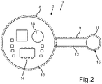
- Fig. 2 shows a schematic representation of an embodiment of the ultrasonic sensor device 3.
- the ultrasonic sensor device 3 comprises a printed circuit board 7 with a first printed circuit board area 8 and a second printed circuit board area 9.
- a first transducer element 10 is arranged in the first printed circuit board area 8.
- a second converter element 11 is arranged in the second circuit board area 9. Both the first transducer element 10 and the second transducer element 11 are designed to emit and / or receive ultrasound signals.
- the second circuit board area 9 is designed as a flexible strip-shaped first circuit board sub-element 12 of the circuit board 7.
- the first circuit board area 8 is designed as the main circuit board element 13 of the circuit board 7.
- the second converter element 11 is arranged on the circuit board sub-element 12 and the first converter element 10 is arranged on the circuit board main element 13.
- Control electronics 14 of the ultrasonic sensor device 3 are also arranged on the main circuit board element 13.
- the second converter element 11 is arranged on a side 15 of the circuit board sub-element 12 facing away from the main circuit board element 13.
- the main circuit board element 13 can be rigid or flexible, for example.
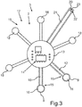
- Fig. 3 shows a further exemplary embodiment of the ultrasonic sensor device 3.
- the second printed circuit board area 9 is designed as the flexible strip-shaped first printed circuit board partial element 12 and the first printed circuit board area 8 is designed as a flexible strip-shaped second printed circuit board partial element 16.
- the second converter element 11 is arranged on the first circuit board sub-element 12.
- the first converter element 10 is arranged on the second circuit board sub-element 16.
- the circuit board sub-elements 12, 16 are connected to the circuit board main element 13 arranged outside the first circuit board region 8 and the second circuit board region 9.
- a plurality of flexible strip-shaped circuit board sub-elements 17 are arranged on the main circuit board element 13. On each part of the circuit board according to the exemplary embodiment, a plurality of circuit board sub-elements 17 have a further converter element 18 of a plurality of converter elements 19 arranged.
- the majority of the circuit board sub-elements 17 are preferably arranged on the circuit board main element 13 such that the circuit board sub-elements are arranged in a star shape around the circuit board main element 13.
- the control electronics 14 is arranged on the main circuit board element 13.
- the main circuit board element 13 is designed in the present case without a converter element. In an embodiment not shown, however, a converter element can also be arranged on the main circuit board element 13.
- a flexible strip-shaped third circuit board sub-element 21 is arranged on the main circuit board element 13 as the third circuit board region 20 of the circuit board 7.
- the third circuit board sub-element 21 is designed without a converter element.
- An interface 23 of the ultrasonic sensor device 3 is formed on a side 22 of the third circuit board sub-element 21 facing away from the main circuit board element 13.
- the interface 23 serves to connect the ultrasound sensor device 3 to the motor vehicle 1.
- the ultrasound sensor device 3 can be connected to a control unit of the motor vehicle 1 via the interface 23.
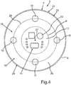
- Fig. 4 shows a further embodiment of the ultrasonic sensor device 3.
- the circuit board 7 is designed as a coherent surface 24 with a round outer contour 25.
- the first circuit board area 8 is designed as a circuit board main element 13.
- the first converter element 10 is arranged on the main circuit board element 13.
- the control electronics 14 are arranged on the main circuit board element 13.
- the second circuit board area 9 is designed as a circuit board frame element 26.
- the circuit board frame element 26 completely frames the main circuit board element 13.
- the second converter element 11 and further converter elements 18 of the plurality of converter elements 19 are arranged on the circuit board frame element 26.
- the second circuit board area 9 is designed as the circuit board frame element 26.
- the transducer elements 11, 18 are arranged symmetrically on the circuit board frame element 26 on a circular path 28 which runs around a longitudinal axis 27 of the circuit board 7.
- a fastening element 30 for fastening to the motor vehicle 1 is arranged in an outer edge region 29 of the printed circuit board 7.
- the fastening element 30 is designed, for example, as an adhesive edge.
- the adhesive edge can be formed completely around the longitudinal axis 27 on the printed circuit board 7.
- Fig. 5 shows a further embodiment of the ultrasonic sensor device 3.
- the first circuit board area 8 is designed as the main circuit board element 13.
- the second circuit board area 9 is designed as the circuit board frame element 26.
- the circuit board 7 is designed as a coherent surface 24 with an angular outer contour 31.
- the first circuit board area 8 is designed as a circuit board main element 13.
- the second circuit board area 9 is designed as the circuit board frame element 26.
- the first converter element 10 is arranged on the main circuit board element 13.
- the control electronics 14 are arranged on the main circuit board element 13.
- the second converter element 11 and the further converter elements 18 of the plurality of converter elements 19 are arranged on the circuit board frame element 26.
- the converter elements 11, 18 on the circuit board frame element 26 are arranged in a grid-like or grid-like manner.
- Fig. 6 shows the ultrasonic sensor device 3 analog Fig. 4 ,
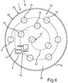
- the first transducer element 10, the second transducer element 11 and the further transducer elements 18 of the majority of the transducer elements 19 are arranged spirally on a spiral path 32 with the longitudinal axis 27 as the origin of the spiral path 32.
- Fig. 7 shows the ultrasonic sensor arrangement 2.
- the ultrasonic sensor device 3 is arranged on the motor vehicle component 4.
- the motor vehicle component 4 can be designed as a curved covering part of the motor vehicle 1.
- the ultrasonic sensor device 3 has the first circuit board area 8 and the second circuit board area 9 as the circuit board frame element 26.
- the main circuit board element 13 lies outside the first Printed circuit board area 8 and the second printed circuit board area 9.
- the control electronics 14 are arranged on the main printed circuit board element 13.
- the first converter element 10 and the second converter element 11 are arranged on the circuit board frame element 26.
- the ultrasonic sensor device 3 is fastened to the motor vehicle component 4 via the fastening element 30.
- the fastening element 30 is arranged on the outer edge region 29 of the circuit board frame element 26.
- the fastening element 30 is designed, for example, as an adhesive edge.
- the ultrasonic sensor device 3 with the printed circuit board 7 and the control electronics 14 arranged thereon is arranged in direct contact with the motor vehicle component 4.
- the circuit board 7 can be adapted to a curvature of the motor vehicle component 4 due to the flexibility in some areas.
- Fig. 8 shows the ultrasonic sensor arrangement 2 analogously to Fig. 7 ,
- the ultrasonic sensor device 3 is surrounded on a side 33 facing away from the motor vehicle component 4 with a protective element 34.
- the protective element 34 can be designed, for example, as a protective film.
- the protective element 34 protects the ultrasonic sensor device 3, for example, against soiling or various mechanical influences.
- the ultrasonic sensor device 3 is completely surrounded on the side 33 facing away from the motor vehicle component 4 by the protective element 34.
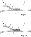
- Fig. 9 shows part of the ultrasonic sensor arrangement 2.
- the second transducer element 11 is attached directly to the motor vehicle component 4.
- the motor vehicle component 4 is formed from sheet metal in the present case.
- the second converter element 11 is arranged on the first circuit board sub-element 12.
- the motor vehicle component 4 can be designed, for example, as a door of the motor vehicle 1.
- Fig. 10 shows the ultrasonic sensor arrangement 2 analogously to Fig. 9 , wherein the motor vehicle component 4 is made of plastic.
- the motor vehicle component 4 can be in the form of a bumper, for example.
- the contacting of the second converter element 11 now takes place by means of an intermediate element 35 which is arranged between the second converter element 11 and the motor vehicle component 4.
- the intermediate element 35 is designed, for example, as an aluminum disk.
- the ultrasonic signal of the second transducer element 11 can thereby more effectively by the Motor vehicle component 4 are sent through to spread in the surrounding area 5.
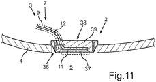
- Fig. 11 shows a further embodiment of the ultrasonic sensor arrangement 2.
- the ultrasonic sensor device 3 is in contrast to 9 and 10 no longer covered, but partially installed open.
- the motor vehicle component 4 thus has an opening 36.
- a pot element 37 extends through the opening 36.
- the pot element 37 can be made of aluminum, for example.
- the second transducer element 11 is arranged in the pot element 37 on a side 38 facing away from the surrounding area 5.
- the second transducer element 11 is arranged on the side opposite the pot element 37 on the first printed circuit board part element 12.
- the second converter element 11 is surrounded by a damping element 39.
- the damping element 39 can be formed, for example, from foam or a damping film or another potting material. The vibration of the second transducer element 11 can be damped by the damping element 39 and can thus be controlled more effectively.
Landscapes
- Engineering & Computer Science (AREA)
- Radar, Positioning & Navigation (AREA)
- Remote Sensing (AREA)
- Physics & Mathematics (AREA)
- Acoustics & Sound (AREA)
- Computer Networks & Wireless Communication (AREA)
- General Physics & Mathematics (AREA)
- Multimedia (AREA)
- Mechanical Engineering (AREA)
- Measurement Of Velocity Or Position Using Acoustic Or Ultrasonic Waves (AREA)
- Transducers For Ultrasonic Waves (AREA)
Description
- Die Erfindung betrifft eine Ultraschallsensorvorrichtung für ein Kraftfahrzeug. Die Ultraschallsensorvorrichtung weist zumindest eine bereichsweise flexibel ausgebildete Leiterplatte mit einem ersten Leiterplattenbereich auf. Auf dem ersten Leiterplattenbereich ist ein Wandlerelement angeordnet, welches zum Aussendung und/oder Empfangen von Ultraschallsignalen ausgebildet ist. Die Erfindung betrifft auch eine Ultraschallsensoranordnung mit zumindest einer an einem Kraftfahrzeugbauteil eines Kraftzeugs angeordneten Ultraschallsensorvorrichtung sowie ein Kraftfahrzeug mit einer Ultraschallsensoranordnung.
- Ultraschallsensorvorrichtungen sind aus dem Stand der Technik bekannt. So zeigt die
WO 2008/125260 A1 einen Ultraschallsensor mit einem Aktor zur Aussendung und/oder einem Sensor zum Empfangen von Schwingungen und einer zugehörigen Elektronik zur Erzeugung und/oder Auswertung der Schwingungen. Es ist vorgesehen, dass der ein Bauteil zum Schwingen anregende, aussendende Aktor und/oder empfangende Sensor ein Piezokeramikelement mit einer vorgebbaren aktorischen und/oder sensorischen Leistung innerhalb eines Piezokeramikmoduls ist, das von außen nicht sichtbar in das Bauteil integriert oder in dem Bauteil applizierbar ist. - Aus der
US 2010/0277040 A1 ist eine Ultraschallsensorvorrichtung bekannt, bei welcher zwei Wandlerelemente auf einer flexiblen Folie angeordnet sind. - Aus der
US 2012/0277639 A1 ist ein Ultraschallwandler bekannt, bei welchem mehrere Wandlerelemente auf einer flexiblen Leiterplatte angeordnet sind. - Es ist Aufgabe der Erfindung, eine Ultraschallsensorvorrichtung, eine Ultraschallsensoranordnung sowie ein Kraftfahrzeug bereitzustellen, mit welchem ein Umgebungsbereich eines Kraftfahrzeugs präziser erfasst werden kann.
- Diese Aufgabe wird erfindungsgemäß durch eine Ultraschallsensorvorrichtung, durch eine Ultraschallsensoranordnung sowie durch ein Kraftfahrzeug mit den Merkmalen gemäß den jeweiligen unabhängigen Ansprüchen gelöst.
- Eine erfindungsgemäße Ultraschallsensorvorrichtung für ein Kraftfahrzeug umfasst eine zumindest bereichsweise flexibel ausgebildete Leiterplatte mit einem ersten Leiterplattenbereich. Auf dem ersten Leiterplattenbereich ist ein Wandlerelement angeordnet, welches zum Aussenden und/oder Empfangen von Ultraschallsignalen ausgebildet ist. Als ein wesentlicher Gedanke der Erfindung ist vorgesehen, dass die Leiterplatte an dem ersten Leiterplattenbereich und/oder an einem zweiten Leiterplattenbereich flexibel ausgebildet ist, und an dem zweiten Leiterplattenbereich ein zu dem ersten Wandlerelement separates zweites Wandlerelement der Ultraschallsensorvorrichtung angeordnet ist, welches zum Aussenden und/oder Empfangen von Ultraschallsignalen ausgebildet ist.
- Durch die erfindungsgemäße Ultraschallsensorvorrichtung kann ein Umgebungsbereich des Kraftfahrzeugs präziser erfasst werden. So kann durch die zumindest zwei Wandlerelemente eine Richtung, aus der ein Echo empfangen wird, bestimmt werden. Weiterhin lässt sich durch zumindest den flexibel ausgebildeten zweiten Leiterplattenbereich eine Abstrahlrichtung der Wandlerelemente in vielfältiger Weise vorgeben.
- Zudem lässt sich die Ultraschallsensorvorrichtung einfacher und in vielfältiger Weise an einem Bauteil des Kraftfahrzeugs anordnen, da die zumindest bereichsweise flexible Leiterplatte an eine durch das Kraftfahrzeugbauteil vorgegebene Form angepasst werden kann. Weiterhin lassen sich die Wandlerelemente in vielfältiger Weise derart ausrichten, dass ein gewünschter Umgebungsbereich des Kraftfahrzeugs präzise abgetastet werden kann.
- Nach dem Stand der Technik ist ein Wandlerelement üblicherweise in einem starren Gehäuse verbaut. Vor allem im verdeckten Verbau beispielsweise hinter einer Türe des Kraftfahrzeugs oder einem Stoßfänger des Kraftfahrzeugs kommt ein starres Bauteil, meist ein Keramikring zum Einsatz. Nachteilig ist dadurch, dass der Verbau beziehungsweise die Platzierung im Kraftfahrzeug oft schwierig ist, da die Konturen des Kraftfahrzeugbauteils oft stark geschwungen sind. Es ergeben sich dann beispielsweise unterschiedliche Schichtdicken des eingesetzten Klebstoffs und die Funktion des Wandlerelements wird nachteilig beeinflusst oder bei starken Wölbungen sogar ganz unmöglich.
- Der erste Leiterplattenbereich und der zweite Leiterplattenbereich liegen insbesondere als unterschiedliche Leiterplattenbereiche vor. Das erste Wandlerelement und/oder das zweite Wandlerelement können beispielsweise als Piezoelement ausgebildet sein. Die Wandlerelemente und vorzugsweise eine Steuerelektronik der Ultraschallsensorvorrichtung sind auf der gemeinsamen Leiterplatte angeordnet. Der Bereich zwischen den Wandlerelementen ist zumindest bereichsweise flexibel ausgebildet. Dadurch können die Wandlerelemente auch direkt auf ein Kraftfahrzeugbauteil des Kraftfahrzeugs aufgeklebt werden. Vorteilhaft ist, dass durch mehrere Wandlerelemente sowohl beim Senden als auch beim Empfangen der Ultraschallsignale eine Richtcharakteristik vorgegeben werden kann. Beim Senden werden die Wandlerelemente mit einem bestimmten Phasenversatz angeregt und der Schall kann somit in eine bestimmte Richtung gelenkt werden. Im Empfangsfall kann dann beispielsweise ein Phasenwinkel gemessen werden und dadurch die Richtung, aus der der Schall eintrifft, bestimmt werden. Insbesondere ist es vorgesehen, dass mehrere Wandlerelemente von der Ultraschallsensorvorrichtung umfasst werden, da sich mit steigender Anzahl der Wandlerelemente eine Ortsauflösung hinsichtlich der Abtastung des Umgebungsbereichs erhöht. Bei einer großen Anzahl von Wandlerelementen kann die Funktion der Ultraschallsensorvorrichtung dann beispielsweise mit einer akustischen Kamera verglichen werden. Es lässt sich dann beispielsweise ein Objekt im Umgebungsbereich mit seinen X-, Y- und Z-Koordinaten im Umgebungsbereich mittels der Ultraschallsensorvorrichtung ermitteln. Die Auswertung der durch die Ultraschallsensorvorrichtung erfassten Information kann dann beispielsweise mit einer Auswerteeinheit in der Ultraschallsensorvorrichtung selbst erfolgen oder aber in einer separat zu der Ultraschallsensorvorrichtung ausgebildeten Auswerteeinheit.
- Durch die flexible Verbindung der Wandlerelemente kann die Ultraschallsensorvorrichtung auch an stark gewölbten Kraftfahrzeugbauteilen angeordnet werden. Die Kraftfahrzeugbauteile, welche beispielsweise starr ausgebildet sind, bedürfen dadurch keiner speziellen Anpassung.
- In einer erfindungsgemäßen Variante ist es vorgesehen, dass die Leiterplatte zumindest ein flexibles streifenförmiges erstes Leiterplattenteilelement als den zweiten Leiterplattenbereich aufweist, welches mit einem Leiterplattenhauptelement der Leiterplatte als den ersten Leiterplattenbereich verbunden ist. Durch das flexible streifenförmige Leiterplattenteilelement kann das zweite Wandlerelement vielfältig zu dem ersten Wandlerelement ausgerichtet werden. Dadurch kann ein Winkel zwischen dem ersten Wandlerelement und dem zweiten Wandlerelement wie gewünscht eingestellt werden. Weiterhin kann das zweite Wandlerelement durch das flexible streifenförmige erste Leiterplattenteilelement auch an Kraftfahrzeugbauteilen mit einer komplexen Kontur oder einer starken Krümmungen angeordnet werden. Das Leiterplattenhauptelement kann beispielsweise kreisscheibenförmig ausgebildet sein und als flexible oder starre Leiterplatte vorliegen.
- In einer weiteren erfindungsgemäßen Variante ist es vorgesehen, dass die Leiterplatte zumindest ein flexibles streifenförmiges erstes Leiterplattenteilelement als den zweiten Leiterplattenbereich aufweist, welches mit einem außerhalb des ersten Leiterplattenbereichs und des zweiten Leiterplattenbereichs angeordneten Leiterplattenhauptelement der Leiterplatte verbunden ist, und die Leiterplatte ein flexibles streifenförmiges zweites Leiterplattenteilelement als den ersten Leiterplattenbereich aufweist, welches mit dem Leiterplattenhauptelement verbunden ist. Das Leiterplattenhauptelement ist dann beispielsweise als dritter Leiterplattenbereich ausgebildet. Dadurch ist dann das zweite Wandlerelement auf dem ersten Leiterplattenteilelement angeordnet und das erste Wandlerelement ist auf dem zweiten Leiterplattenteilelement angeordnet. Optional kann auf dem Leiterplattenhauptelement ein drittes Wandlerelement angeordnet sein. Durch das flexible streifenförmige erste Leiterplattenteilelement und das flexible streifenförmige zweite Leiterplattenteilelement können die Wandlerelemente flexibler zueinander ausgerichtet werden, wodurch der Umgebungsbereich des Kraftfahrzeugs präziser erfasst werden kann. Weiterhin lassen sich die Wandlerelemente durch die flexiblen streifenförmigen Leiterplattenteilelemente auch an Kraftfahrzeugbauteilen mit komplexen Konturen in vielfältiger Weise anordnen.
- Insbesondere ist es vorgesehen, dass zumindest eines der Wandlerelemente an einer dem Leiterplattenhauptelement abgewandten Seite des jeweiligen Leiterplattenteilelements angeordnet ist. Dadurch kann die Positionierung der Wandlerelemente wiederum vielfältiger an dem Kraftfahrzeugbauteil erfolgen, da die Freiheit bei der Positionierung durch den größeren Abstand zwischen den Wandlerelementen und dem Leiterplattenhauptelement erhöht wird.
- Erfindungsgemäß ist es vorgesehen, dass die Leiterplatte zumindest ein flexibles streifenförmiges drittes Leiterplattenteilelement als dritten Leiterplattenbereich umfasst, welches an einer dem Leiterplattenhauptelement abgewandten Seite eine Schnittstelle zum Anschluss an das Kraftfahrzeug aufweist und ohne Wandlerelement ausgebildet ist. Dadurch kann die Ultraschallsensorvorrichtung auch an unzugänglichen Stellen des Kraftfahrzeugbauteils angeordnet werden und dennoch zuverlässig mit dem Kraftfahrzeug verbunden werden. Vorzugsweise wird die gesamte Ultraschallvorrichtung und somit sämtliche Wandlerelemente der Ultraschallsensorvorrichtung über die Schnittstelle an das Kraftfahrzeug angeschlossen. Es ist somit auch für mehrere Wandlerelemente nur eine Schnittstelle zum Anschluss an das Kraftfahrzeug notwendig. Dadurch kann die Ultraschallsensorvorrichtung bauteilärmer und effektiver an das Kraftfahrzeug angeschlossen werden.
- In einer weiteren Ausführungsform ist es vorzugsweise vorgesehen, dass die Leiterplatte als zusammenhängende Fläche mit runder Außenkontur oder mit eckiger Außenkontur ausgebildet ist, und ein als der erste Leiterplattenbereich ausgebildetes Leiterplattenhauptelement der Leiterplatte von einem als der zweite Leiterplattenbereich ausgebildeten Leiterplattenrahmenelement der Leiterplatte vollständig umrahmt ist. Dadurch ist auf dem Leiterplattenhauptelement das erste Wandlerelement angeordnet und auf dem Leiterplattenrahmenelement ist zumindest das zweite Wandlerelement angeordnet. Das Leiterplattenhauptelement kann dabei beispielsweise starr oder flexibel ausgebildet sein. Durch die Anordnung des zweiten Leiterplattenhauptelements auf dem Leiterplattenrahmenelement kann das zweite Wandlerelement wiederum in vielfältiger Weise zu dem ersten Wandlerelement hin ausgerichtet werden. Der Umgebungsbereich des Kraftfahrzeugs kann dadurch präziser erfasst werden. Zudem kann die Ultraschallsensorvorrichtung auch wiederum einfacher an Kraftfahrzeugbauteilen mit einer komplexen Geometrie angeordnet werden. Weiterhin vorteilhaft an der Ultraschallsensorvorrichtung mit dem Leiterplattenrahmenelement ist beispielsweise, dass das Leiterplattenrahmenelement durch die ringförmige Ausgestaltung kompakt und robust ausgebildet ist. Weiterhin wird durch das Leiterplattenrahmenelement eine größere Oberfläche für die Anordnung von mehreren Wandlerelementen bereitgestellt.
- In einer weiteren Ausführungsform ist es vorzugsweise vorgesehen, dass die Leiterplatte als zusammenhängende Fläche mit runder Außenkontur oder mit eckiger Außenkontur ausgebildet ist, und ein außerhalb des ersten Leiterplattenbereichs und des zweiten Leiterplattenbereichs angeordnetes Leiterplattenhauptelement der Leiterplatte von einem als der erste Leiterplattenbereich und der zweite Leiterplattenbereich ausgebildeten Leiterplattenrahmenelement der Leiterplatte vollständig umrahmt ist. Vorzugsweise ist auf dem Leiterplattenhauptelement kein Wandlerelement angeordnet. Das erste Wandlerelement und zumindest das zweite Wandlerelement sind auf dem Leiterplattenrahmenelement angeordnet. Dadurch sind die Wandlerelemente dann insbesondere nur auf dem flexibel ausgebildeten Bereich der Leiterplatte angeordnet. Vorteilhaft ist daran, dass eine beispielsweise auf dem Leiterplattenhauptelement angeordnete Steuerelektronik der Ultraschallsensorvorrichtung vor dem Einfluss einer durch die Wandlerelemente entstehenden Schwingung bewahrt werden kann. Dadurch kann die Ultraschallsensorvorrichtung genauer und zuverlässiger betrieben werden. Weiterhin ist es vorzugsweise vorgesehen, dass eine Mehrzahl von mehr als zwei Wandlerelementen der Ultraschallsensorvorrichtung auf dem Leiterplattenrahmenelement angeordnet ist, und die Wandlerelemente symmetrisch auf einer um eine Längsachse der Leiterplatte umlaufenden Kreisbahn oder spiralförmig auf einer Spiralbahn mit der Längsachse als Ursprung der Spiralbahn angeordnet sind. Dadurch kann die Ortsauflösung der Ultraschallsensorvorrichtung weiterhin erhöht werden. Der Umgebungsbereich des Kraftfahrzeugs kann dadurch also präziser erfasst werden. Durch die Mehrzahl der Wandlerelemente kann die Position eines Objekts im Umgebungsbereich genauer bestimmt werden. Es kann somit bestimmt werden, ob das Objekt in einem relevanten Bereich liegt und somit beispielsweise ein Hindernis für das Kraftfahrzeug darstellt, oder ob das Objekt ausgeblendet werden soll, da es außerhalb des relevanten Bereichs liegt. Durch das Anordnen der Wandlerelemente in symmetrischer Form oder in Spiralform kann die Ultraschallsensorvorrichtung für vielfältige Anforderungen und komplexe Kraftfahrzeugbauteilformen bereitgestellt werden. Durch die in vielfältiger Weise mögliche Anordnung der Wandlerelemente auf der Leiterplatte, beispielsweise symmetrisch auf der Kreisbahn oder spiralförmig auf der Spiralbahn, kann jeweils ein unterschiedliches Interferenzbild des Ultraschallsignals der Ultraschallsensorvorrichtung bereitgestellt werden. Das Interferenzbild kann dann beispielsweise derart gewählt werden, dass der Umgebungsbereich genauer und zuverlässiger erfasst wird.
- Insbesondere ist es vorgesehen, dass eine Steuerelektronik der Ultraschallsensorvorrichtung, welche mit dem ersten Wandlerelement und/oder mit dem zweiten Wandlerelement elektrisch verbunden ist, auf dem Leiterplattenhauptelement angeordnet ist. Durch die Anordnung der Steuerelektronik auf dem Leiterplattenhauptelement kann diese mit jedem der Wandlerelemente auf kurzem Weg verbunden werden. Weiterhin können die Wandlerelemente derart beabstandet von der Steuerelektronik auf der Leiterplatte angeordnet werden, dass eine Schwingung der Wandlerelemente nicht auf die Steuerelektronik übertragen wird. Insbesondere teilen sich das erste Wandlerelement und das zweite Wandlerelement die Steuerelektronik. Die Ultraschallsensorvorrichtung kann dadurch bauteilärmer und effektiver ausgebildet werden, als wenn jedes Wandlerelement eine eigene Steuerelektronik aufweisen würde.
- Weiterhin kann es vorgesehen sein, dass das Leiterplattenhauptelement starr ausgebildet ist. So kann das Leiterplattenhauptelement starr ausgebildet sein, während das Leiterplattenrahmenelement flexibel ausgebildet ist. Vorteilhaft ist beispielsweise, dass durch das starr ausgebildete Leiterplattenhauptelement eine einfache Möglichkeit zur Anordnung der Steuerelektronik auf dem Leiterplattenhauptelement bereitgestellt wird. Die Ultraschallsensorvorrichtung kann dadurch beispielsweise auch robuster bereitgestellt werden.
- Insbesondere ist es vorgesehen, dass in einem äußeren Randbereich der Leiterplatte ein Befestigungselement, insbesondere ein Kleberand, zur Befestigung an dem Kraftfahrzeug angeordnet ist. Der Kleberand kann beispielsweise vollständig umlaufend um einen äußeren Rand des Leiterplattenrahmenelements angeordnet sein. Der Kleberand kann aber beispielsweise auch an der dem Leiterplattenhauptelement abgewandten Seite des ersten und/oder des zweiten Leiterplattenteilelements angeordnet sein. Durch das Befestigungselement kann die Ultraschallsensorvorrichtung einfach und platzsparend an dem Kraftfahrzeugbauteil befestigt werden. Durch den Kleberand kann beispielsweise auch eine Befestigung der Ultraschallsensorvorrichtung an schwer zugänglichen Stellen des Kraftfahrzeugbauteils erfolgen.
- Die Erfindung betrifft auch eine Ultraschallsensoranordnung mit zumindest einer an einem Kraftfahrzeugbauteil eines Kraftfahrzeugs angeordneten erfindungsgemäßen Ultraschallsensorvorrichtung .
- Insbesondere ist es vorgesehen, dass eine zumindest bereichsweise flexible Leiterplatte der Ultraschallsensorvorrichtung mit einer auf der Leiterplatte angeordneten Steuerelektronik der Ultraschallsensorvorrichtung unmittelbar an dem Kraftfahrzeugbauteil anliegend angeordnet ist. So ist bei der Ultraschallsensorvorrichtung neben zumindest zwei Wandlerelementen der Ultraschallsensorvorrichtung auch die Leiterplatte mit der Steuerelektronik unmittelbar an einer Innenseite des Kraftfahrzeugbauteils, beispielsweise eines Verkleidungsteils, angeordnet. Dies hat eine platzsparende Wirkung und ermöglicht das Anordnen der Ultraschallsensorvorrichtung in vielfältiger Weise an dem Kraftfahrzeugbauteil. Auch kann die Ultraschallsensorvorrichtung dadurch an Kraftfahrzeugbauteilen mit einer komplexen Geometrie, beispielsweise starken Krümmungen, einfacher angeordnet werden.
- Weiterhin ist es vorzugsweise vorgesehen, dass die Ultraschallsensorvorrichtung auf einer dem Kraftfahrzeugbauteil abgewandten Seite zumindest teilweise mit einem Schutzelement umgeben ist. Das Schutzelement kann beispielsweise als Schutzfolie ausgebildet sein. Durch das Schutzelement wird die Ultraschallsensorvorrichtung beispielsweise gegenüber dem Einfluss von Staub oder Feuchtigkeit geschützt. Die Ultraschallsensorvorrichtung kann also auf einer dem Kraftfahrzeugbauteil zugewandten Seite von dem Kraftfahrzeugbauteil selbst geschützt sein und auf der dem Kraftfahrzeugbauteil abgewandten Seite kann die Ultraschallsensorvorrichtung durch das Schutzelement geschützt werden. Das Schutzelement kann beispielsweise mit einem am äußeren Rand des Schutzelements umlaufenden Klebestreifen auf das Kraftfahrzeugbauteil aufgeklebt werden.
- Weiterhin kann es vorgesehen sein, dass die Ultraschallsensoranordnung zusätzlich zu der ersten Ultraschallsensorvorrichtung eine zweite Ultraschallsensorvorrichtung umfasst, und die erste Ultraschallsensorvorrichtung mit der zweiten Ultraschallsensorvorrichtung, insbesondere drahtlos gekoppelt ist. Die Kopplung der ersten Ultraschallsensorvorrichtung mit der zweiten Ultraschallsensorvorrichtung kann beispielsweise kabelgebunden oder drahtlos erfolgen. Vorteilhaft ist, dass dadurch mehrere Ultraschallsensorvorrichtungen in einfacher Weise kombiniert werden können. So kann der Anschluss der Ultraschallsensoranordnung beispielsweise lediglich über die erste Ultraschallsensorvorrichtung an das Kraftfahrzeug erfolgen, während die zweite Ultraschallsensorvorrichtung über die erste Ultraschallsensorvorrichtung an das Kraftfahrzeug angebunden ist. Dadurch wird die Ultraschallsensoranordnung effektiv und funktionsreich bereitgestellt.
- Die Erfindung betrifft auch ein Kraftfahrzeug mit einer erfindungsgemäßen Ultraschallsensoranordnung.
- Weitere Merkmale der Erfindung ergeben sich aus den Ansprüchen. Die vorstehend in der Beschreibung genannten Merkmale und Merkmalskombinationen, sowie die nachfolgend in der Figurenbeschreibung genannten und/oder in den Figuren alleine gezeigten Merkmale und Merkmalskombinationen sind nicht nur in der jeweils angegebenen Kombination, sondern auch in anderen Kombinationen oder in Alleinstellung verwendbar, ohne den Rahmen der Erfindung zu verlassen.
- Dabei zeigen:
- Fig. 1
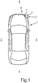
- eine schematische Draufsicht auf ein erfindungsgemäßes Kraftfahrzeug mit einer Ultraschallsensoranordnung;
- Fig. 2
- eine schematische Darstellung einer erfindungsgemäßen Ultraschallsensorvorrichtung der Ultraschallsensoranordnung;
- Fig. 3
- eine schematische Darstellung eines weiteren Ausführungsbeispiels der Ultraschallsensorvorrichtung ;
- Fig. 4
- eine schematische Darstellung eines weiteren Ausführungsbeispiels der Ultraschallsensorvorrichtung mit einem Leiterplattenhauptelement und einem Leiterplattenrahmenelement, wobei Wandlerelemente der Ultraschallsensorvorrichtung symmetrisch auf einer Kreisbahn angeordnet sind;
- Fig. 5
- eine schematische Darstellung eines weiteren Ausführungsbeispiels der Ultraschallsensorvorrichtung, bei welcher die Wandlerelemente rasterartig auf dem Leiterplattenrahmenelement angeordnet sind;
- Fig. 6
- eine schematische Darstellung eines weiteren Ausführungsbeispiels der Ultraschallsensorvorrichtung, bei welcher die Wandlerelemente spiralförmig auf einer Spiralbahn auf der Leiterplatte angeordnet sind;
- Fig. 7
- eine schematische Darstellung der Ultraschallsensoranordnung, bei welcher eine Steuerelektronik der Ultraschallsensorvorrichtung unmittelbar anliegend an einem Kraftfahrzeugbauteil des Kraftfahrzeugs angeordnet ist;
- Fig. 8
- eine schematische Darstellung der Ultraschallsensoranordnung, bei welcher die Ultraschallsensorvorrichtung mit einem Schutzelement umgeben ist;
- Fig. 9
- eine schematische Darstellung eines in verdeckter Verbauweise an dem Kraftfahrzeugbauteil angeordneten Wandlerelements der Ultraschallsensorvorrichtung ;
- Fig. 10
- eine schematische Darstellung eines in verdeckter Verbauweise mittels eines Zwischenelements an dem Kraftfahrzeugbauteil angeordneten Wandlerelements der Ultraschallsensorvorrichtung; und
- Fig. 11
- eine schematische Darstellung eines in unverdeckter Verbauweise angeordneten Wandlerelements der Ultraschallsensorvorrichtung.
- In den Figuren werden gleiche oder funktionsgleiche Elemente mit den gleichen Bezugszeichen versehen.
- In
Fig. 1 ist schematisch eine Draufsicht auf ein Kraftfahrzeug 1 mit einer Ultraschallsensoranordnung 2 gezeigt. Die Ultraschallsensoranordnung 2 umfasst eine Ultraschallsensorvorrichtung 3, welche an einem Kraftfahrzeugbauteil 4 des Kraftfahrzeugs 1 angeordnet ist. Das Kraftfahrzeugbauteil 4 kann dabei beispielsweise als Verkleidungsteil des Kraftfahrzeugs 1, wie beispielsweise ein Stoßfänger, vorliegen. Die Anordnung der Ultraschallsensorvorrichtung 3 an dem Kraftfahrzeug 1 ist vielfältig möglich, vorzugsweise allerdings so, dass ein Umgebungsbereich 5 des Kraftfahrzeugs 1 mit der Ultraschallsensorvorrichtung 3 zumindest teilweise erfasst werden kann. Vorliegend ist die Ultraschallsensorvorrichtung 3 an einer Front 6 des Kraftfahrzeugs 1 angeordnet. -
Fig. 2 zeigt eine schematische Darstellung eines Ausführungsbeispiels der Ultraschallsensorvorrichtung 3. Die Ultraschallsensorvorrichtung 3 umfasst eine Leiterplatte 7 mit einem ersten Leiterplattenbereich 8 und einem zweiten Leiterplattenbereich 9. In dem ersten Leiterplattenbereich 8 ist ein erstes Wandlerelement 10 angeordnet. In dem zweiten Leiterplattenbereich 9 ist ein zweites Wandlerelement 11 angeordnet. Sowohl das erste Wandlerelement 10 als auch das zweite Wandlerelement 11 sind zum Aussenden und/oder Empfangen von Ultraschallsignalen ausgebildet. Der zweite Leiterplattenbereich 9 ist ausgebildet als ein flexibles streifenförmiges erstes Leiterplattenteilelement 12 der Leiterplatte 7. Der erste Leiterplattenbereich 8 ist als Leiterplattenhauptelement 13 der Leiterplatte 7 ausgebildet. Somit ist das zweite Wandlerelement 11 auf dem Leiterplattenteilelement 12 angeordnet und das erste Wandlerelement 10 ist auf dem Leiterplattenhauptelement 13 angeordnet. Auf dem Leiterplattenhauptelement 13 ist zudem noch eine Steuerelektronik 14 der Ultraschallsensorvorrichtung 3 angeordnet. Weiterhin ist das zweite Wandlerelement 11 auf einer dem Leiterplattenhauptelement 13 abgewandten Seite 15 des Leiterplattenteilelements 12 angeordnet. - Das Leiterplattenteilelement 12 ist aus einer flexiblen Leiterplatte beziehungsweise einer flexiblen Leiterbahn ausgebildet und kann dadurch in vielfältiger Weise gebogen werden. Das erste Wandlerelement 10 und/oder das zweite Wandlerelement 11 sind vorzugsweise als Piezoelement ausgebildet. Durch die Wandlerelemente 10, 11 werden Ultraschallsignale beziehungsweise Ultraschallwellen in den Umgebungsbereich 5 des Kraftfahrzeugs 1 ausgesendet und/oder aus dem Umgebungsbereich 5 empfangen. Dadurch kann dann beispielsweise ein Abstand zu einem Objekt in dem Umgebungsbereich 5 des Kraftfahrzeugs 1 bestimmt werden. Durch die zwei Wandlerelemente 10, 11 kann eine mehrdimensionale Position des Objekts in dem Umgebungsbereich 5 bestimmt werden.
- Das Leiterplattenhauptelement 13 kann beispielsweise starr oder flexibel ausgebildet sein.
-
Fig. 3 zeigt ein weiteres Ausführungsbeispiel der Ultraschallsensorvorrichtung 3. Der zweite Leiterplattenbereich 9 ist als das flexible streifenförmige erste Leiterplattenteilelement 12 ausgebildet und der erste Leiterplattenbereich 8 ist als ein flexibles streifenförmiges zweites Leiterplattenteilelement 16 ausgebildet. Auf dem ersten Leiterplattenteilelement 12 ist das zweite Wandlerelement 11 angeordnet. Auf dem zweiten Leiterplattenteilelement 16 ist das erste Wandlerelement 10 angeordnet. Die Leiterplattenteilelemente 12, 16 sind an das außerhalb des ersten Leiterplattenbereichs 8 und des zweiten Leiterplattenbereichs 9 angeordneten Leiterplattenhauptelement 13 angebunden. - An das Leiterplattenhauptelement 13 ist eine Mehrzahl von flexiblen streifenförmigen Leiterplattenteilelementen 17 angeordnet. Auf jedem Leiterplattenteilelement der Mehrzahl der Leiterplattenteilelemente 17 ist gemäß dem Ausführungsbeispiel ein weiteres Wandlerelement 18 einer Mehrzahl von Wandlerelementen 19 angeordnet.
- Die Mehrzahl der Leiterplattenteilelemente 17 ist vorzugsweise derart an dem Leiterplattenhauptelement 13 angeordnet sein, dass die Leiterplattenteilelemente sternförmig um das Leiterplattenhauptelement 13 herum angeordnet sind.
- Die Steuerelektronik 14 ist auf dem Leiterplattenhauptelement 13 angeordnet. Das Leiterplattenhauptelement 13 ist vorliegend ohne Wandlerelement ausgebildet. In einem nicht weiter dargestellten Ausführungsbeispiel kann jedoch auch ein Wandlerelement auf dem Leiterplattenhauptelement 13 angeordnet sein.
- An das Leiterplattenhauptelement 13 ist als dritten Leiterplattenbereich 20 der Leiterplatte 7 ein flexibles streifenförmiges drittes Leiterplattenteilelement 21 angeordnet. Das dritte Leiterplattenteilelement 21 ist ohne Wandlerelement ausgebildet. Auf einer dem Leiterplattenhauptelement 13 abgewandten Seite 22 des dritten Leiterplattenteilelements 21 ist eine Schnittstelle 23 der Ultraschallsensorvorrichtung 3 ausgebildet. Die Schnittstelle 23 dient zum Anschluss der Ultraschallsensorvorrichtung 3 an das Kraftfahrzeug 1. Beispielsweise kann die Ultraschallsensorvorrichtung 3 über die Schnittstelle 23 an eine Steuereinheit des Kraftfahrzeugs 1 angeschlossen werden.
-
Fig. 4 zeigt ein weiteres Ausführungsbeispiel der Ultraschallsensorvorrichtung 3. Die Leiterplatte 7 ist als zusammenhängende Fläche 24 mit einer runden Außenkontur 25 ausgebildet. Der erste Leiterplattenbereich 8 ist als Leiterplattenhauptelement 13 ausgebildet. Auf dem Leiterplattenhauptelement 13 ist das erste Wandlerelement 10 angeordnet. Weiterhin ist auf dem Leiterplattenhauptelement 13 die Steuerelektronik 14 angeordnet. - Der zweite Leiterplattenbereich 9 ist als Leiterplattenrahmenelement 26 ausgebildet. Das Leiterplattenrahmenelement 26 umrahmt das Leiterplattenhauptelement 13 vollständig. Auf dem Leiterplattenrahmenelement 26 ist das zweite Wandlerelement 11 und weitere Wandlerelemente 18 der Mehrzahl der Wandlerelemente 19 angeordnet. Der zweite Leiterplattenbereich 9 ist als das Leiterplattenrahmenelement 26 ausgebildet.
- Die Wandlerelemente 11, 18 sind auf dem Leiterplattenrahmenelement 26 symmetrisch auf einer um eine Längsachse 27 der Leiterplatte 7 umlaufende Kreisbahn 28 angeordnet.
- In einem äußeren Randbereich 29 der Leiterplatte 7 ist ein Befestigungselement 30 zur Befestigung an dem Kraftfahrzeug 1 angeordnet. Das Befestigungselement 30 ist beispielsweise als Kleberand ausgebildet. Der Kleberand kann dabei vollständig um die Längsachse 27 umlaufend an der Leiterplatte 7 ausgebildet sein.
- In einem nicht weiter dargestellten Ausführungsbeispiel analog zu
Fig. 4 ist das erste Wandlerelement 10 nicht auf dem Leiterplattenhauptelement 13 angeordnet, sondern ebenso wie das zweite Wandlerelement 11 auf dem Leiterplattenrahmenelement 26. Das Leiterplattenrahmenelement 26 weist somit den ersten Leiterplattenbereich 8 und den zweiten Leiterplattenbereich 9 auf. Dadurch kann das Leiterplattenhauptelement 13 auch ohne entsprechendes Wandlerelement bereitgestellt werden. -
Fig. 5 zeigt ein weiteres Ausführungsbeispiel der Ultraschallsensorvorrichtung 3. Der erste Leiterplattenbereich 8 ist als das Leiterplattenhauptelement 13 ausgebildet. Der zweite Leiterplattenbereich 9 ist als das Leiterplattenrahmenelement 26 ausgebildet. Die Leiterplatte 7 ist als zusammenhänge Fläche 24 mit eckiger Außenkontur 31 ausgebildet. Der erste Leiterplattenbereich 8 ist als Leiterplattenhauptelement 13 ausgebildet. Der zweite Leiterplattenbereich 9 ist als das Leiterplattenrahmenelement 26 ausgebildet. Auf dem Leiterplattenhauptelement 13 ist das erste Wandlerelement 10 angeordnet. Weiterhin ist auf dem Leiterplattenhauptelement 13 die Steuerelektronik 14 angeordnet. Auf dem Leiterplattenrahmenelement 26 ist das zweite Wandlerelement 11 und die weiteren Wandlerelemente 18 der Mehrzahl der Wandlerelemente 19 angeordnet. Die Wandlerelemente 11, 18 auf dem Leiterplattenrahmenelement 26 sind rasterartig beziehungsweise gitterartig angeordnet. -
Fig. 6 zeigt die Ultraschallsensorvorrichtung 3 analogFig. 4 . Das erste Wandlerelement 10, das zweite Wandlerelement 11 und die weiteren Wandlerelemente 18 der Mehrzahl der Wandlerelemente 19 sind spiralförmig auf einer Spiralbahn 32 mit der Längsachse 27 als Ursprung der Spiralbahn 32 angeordnet. -
Fig. 7 zeigt die Ultraschallsensoranordnung 2. An dem Kraftfahrzeugbauteil 4 ist die Ultraschallsensorvorrichtung 3 angeordnet. Das Kraftfahrzeugbauteil 4 kann dabei als gekrümmtes Verkleidungsteil des Kraftfahrzeugs 1 ausgebildet sein. Die Ultraschallsensorvorrichtung 3 weist dabei den ersten Leiterplattenbereich 8 und den zweiten Leiterplattenbereich 9 als das Leiterplattenrahmenelement 26 auf. Das Leiterplattenhauptelement 13 liegt gemäß dem Ausführungsbeispiel außerhalb des ersten Leiterplattenbereichs 8 und des zweiten Leiterplattenbereichs 9. Auf dem Leiterplattenhauptelement 13 ist die Steuerelektronik 14 angeordnet. Auf dem Leiterplattenrahmenelement 26 sind das erste Wandlerelement 10 und das zweite Wandlerelement 11 angeordnet. Die Ultraschallsensorvorrichtung 3 ist über das Befestigungselement 30 an dem Kraftfahrzeugbauteil 4 befestigt. Das Befestigungselement 30 ist an dem äußeren Randbereich 29 des Leiterplattenrahmenelements 26 angeordnet. Das Befestigungselement 30 ist beispielsweise als Kleberand ausgebildet. Gemäß dem Ausführungsbeispiel ist die Ultraschallsensorvorrichtung 3 mit der Leiterplatte 7 und der darauf angeordneten Steuerelektronik 14 unmittelbar mit dem Kraftfahrzeugbauteil 4 anliegend angeordnet. Die Leiterplatte 7 kann durch die bereichsweise Flexibilität an eine Krümmung des Kraftfahrzeugbauteils 4 angepasst werden. -
Fig. 8 zeigt die Ultraschallsensoranordnung 2 analog zuFig. 7 . Ergänzend zu dem Ausführungsbeispiel vonFig. 7 ist die Ultraschallsensorvorrichtung 3 auf einer dem Kraftfahrzeugbauteil 4 abgewandten Seite 33 mit einem Schutzelement 34 umgeben. Das Schutzelement 34 kann dabei beispielsweise als Schutzfolie ausgebildet sein. Das Schutzelement 34 schützt die Ultraschallsensorvorrichtung 3 beispielsweise vor Verschmutzung oder vielfältigen mechanischen Einwirkungen. Gemäß dem Ausführungsbeispiel vonFig. 8 ist die Ultraschallsensorvorrichtung 3 auf der dem Kraftfahrzeugbauteil 4 abgewandten Seite 33 vollständig von dem Schutzelement 34 umgeben. -
Fig. 9 zeigt einen Teil der Ultraschallsensoranordnung 2. Das zweite Wandlerelement 11 ist direkt auf dem Kraftfahrzeugbauteil 4 angebracht. Das Kraftfahrzeugbauteil 4 ist vorliegend aus Blech ausgebildet. Das zweite Wandlerelement 11 ist auf dem ersten Leiterplattenteilelement 12 angeordnet. Das Kraftfahrzeugbauteil 4 kann beispielsweise als Türe des Kraftfahrzeugs 1 ausgebildet sein. -
Fig. 10 zeigt die Ultraschallsensoranordnung 2 analog zuFig. 9 , wobei das Kraftfahrzeugbauteil 4 aus Kunststoff ausgebildet ist. Das Kraftfahrzeugbauteil 4 kann beispielsweise in Form eines Stoßfängers vorliegen. Die Kontaktierung des zweiten Wandlerelements 11 erfolgt nun mittels eines Zwischenelements 35, welches zwischen dem zweiten Wandlerelement 11 und dem Kraftfahrzeugbauteil 4 angeordnet ist. Das Zwischenelement 35 ist beispielsweise als Aluminiumscheibe ausgebildet. Das Ultraschallsignal des zweiten Wandlerelements 11 kann dadurch effektiver durch das Kraftfahrzeugbauteil 4 hindurch geschickt werden, um sich in dem Umgebungsbereich 5 auszubreiten. -
Fig. 11 zeigt ein weiteres Ausführungsbeispiel der Ultraschallsensoranordnung 2. Die Ultraschallsensorvorrichtung 3 ist im Gegensatz zuFig. 9 und Fig. 10 nun nicht mehr verdeckt, sondern teilweise offen verbaut. So weist das Kraftfahrzeugbauteil 4 eine Öffnung 36 auf. Durch die Öffnung 36 erstreckt sich ein Topfelement 37. Das Topfelement 37 kann beispielsweise aus Aluminium ausgebildet sein. In dem Topfelement 37 ist auf einer dem Umgebungsbereich 5 abgewandten Seite 38 das zweite Wandlerelement 11 angeordnet. Das zweite Wandlerelement 11 ist auf der dem Topfelement 37 gegenüberliegenden Seite auf dem ersten Leiterplattenteilelement 12 angeordnet. Weiterhin wird das zweite Wandlerelement 11 von einem Dämpfungselement 39 umgeben. Das Dämpfungselement 39 kann dabei beispielsweise aus Schaum oder einer Verdämpfungsfolie oder einem sonstigen Vergußmaterial ausgebildet sein. Durch das Dämpfungselement 39 kann die Schwingung des zweiten Wandlerelements 11 gedämpft und dadurch effektiver kontrolliert werden.
Claims (9)
- Ultraschallsensorvorrichtung (3) für ein Kraftfahrzeug (1), mit einer zumindest bereichsweise flexibel ausgebildeten Leiterplatte (7) mit einem ersten Leiterplattenbereich (8), auf welchem ein Wandlerelement (10) angeordnet ist, welches zum Aussenden und/oder Empfangen von Ultraschallsignalen ausgebildet ist, wobei
die Leiterplatte (7) an dem ersten Leiterplattenbereich (8) und/oder an einem zweiten Leiterplattenbereich (9) flexibel ausgebildet ist, und an dem zweiten Leiterplattenbereich (9) ein zu dem ersten Wandlerelement (10) separates zweites Wandlerelement (11) der Ultraschallsensorvorrichtung (3) angeordnet ist, welches zum Aussenden und/oder Empfangen von Ultraschallsignalen ausgebildet ist, und wobei die Leiterplatte (7) zumindest ein flexibles streifenförmiges erstes Leiterplattenteilelement (12) als den zweiten Leiterplattenbereich (9) aufweist, welches mit einem Leiterplattenhauptelement (13) der Leiterplatte (7) als den ersten
Leiterplattenbereich (8) verbunden ist oder welches mit einem außerhalb des ersten Leiterplattenbereichs (8) und des zweiten Leiterplattenbereichs (9) angeordneten Leiterplattenhauptelement (13) der Leiterplatte (7) verbunden ist, und die Leiterplatte (7) ein flexibles streifenförmiges zweites Leiterplattenteilelement (16) als den ersten Leiterplattenbereich (8) aufweist, welches mit dem Leiterplattenhauptelement (13) verbunden ist, dadurch gekennzeichnet, dass die Leiterplatte (7) zumindest ein flexibles streifenförmiges drittes Leiterplattenteilelement (21) als dritten Leiterplattenbereich (20) umfasst, welches an einer dem Leiterplattenhauptelement (13) abgewandten Seite (22) eine Schnittstelle (23) zum Anschluss an das Kraftfahrzeug (1) aufweist und ohne Wandlerelement ausgebildet ist. - Ultraschallsensorvorrichtung (3) nach Anspruch 1,
dadurch gekennzeichnet, dass
zumindest eines der Wandlerelemente (10, 11) an einer dem Leiterplattenhauptelement (13) abgewandten Seite (15) des jeweiligen Leiterplattenteilelements (12, 16) angeordnet ist. - Ultraschallsensorvorrichtung (3) nach Anspruch 1 oder 2,
dadurch gekennzeichnet, dass
eine Steuerelektronik (14) der Ultraschallsensorvorrichtung (3), welche mit dem ersten Wandlerelement (10) und/oder mit dem zweiten Wandlerelement (11) elektrisch verbunden ist, auf dem Leiterplattenhauptelement (13) angeordnet ist. - Ultraschallsensorvorrichtung (3) nach einem der Ansprüche 1 bis 3,
dadurch gekennzeichnet, dass
das Leiterplattenhauptelement (13) starr ausgebildet ist. - Ultraschallsensorvorrichtung (3) nach einem der vorhergehenden Ansprüche,
dadurch gekennzeichnet, dass
in einem äußeren Randbereich (29) der Leiterplatte (7) ein Befestigungselement (30), insbesondere ein Kleberand, zur Befestigung an dem Kraftfahrzeug (1) angeordnet ist. - Ultraschallsensoranordnung (2) mit einem Befestigungselement (30) und zumindest einer an einem Kraftfahrzeugbauteil
(4) eines Kraftfahrzeugs (1) angeordneten Ultraschallsensorvorrichtung (3) nach einem der vorhergehenden Ansprüche. - Ultraschallsensoranordnung (2) nach Anspruch 6,
dadurch gekennzeichnet, dass
eine zumindest bereichsweise flexible Leiterplatte (7) der Ultraschallsensorvorrichtung (3) mit einer auf der Leiterplatte (7) angeordneten Steuerelektronik (14) der Ultraschallsensorvorrichtung (3) unmittelbar an dem Kraftfahrzeugbauteil (4) anliegend angeordnet ist. - Ultraschallsensoranordnung (2) nach Anspruch 6 oder 7,
dadurch gekennzeichnet, dass
die Ultraschallsensorvorrichtung (3) auf einer dem Kraftfahrzeugbauteil (4) abgewandten Seite (33) zumindest teilweise mit einem Schutzelement (34) umgeben ist. - Kraftfahrzeug (1) mit einer Ultraschallsensoranordnung (2) nach einem der Ansprüche 6 bis 8.
Applications Claiming Priority (2)
| Application Number | Priority Date | Filing Date | Title |
|---|---|---|---|
| DE102015122417.8A DE102015122417A1 (de) | 2015-12-21 | 2015-12-21 | Ultraschallsensorvorrichtung mit einer zumindest bereichsweise flexiblen Leiterplatte, Ultraschallsensoranordnung und Kraftfahrzeug |
| PCT/EP2016/080732 WO2017108494A1 (de) | 2015-12-21 | 2016-12-13 | Ultraschallsensorvorrichtung mit einer zumindest bereichsweise flexiblen leiterplatte, ultraschallsensoranordnung und kraftfahrzeug |
Publications (2)
| Publication Number | Publication Date |
|---|---|
| EP3393680A1 EP3393680A1 (de) | 2018-10-31 |
| EP3393680B1 true EP3393680B1 (de) | 2020-01-15 |
Family
ID=57588997
Family Applications (1)
| Application Number | Title | Priority Date | Filing Date |
|---|---|---|---|
| EP16815786.5A Active EP3393680B1 (de) | 2015-12-21 | 2016-12-13 | Ultraschallsensorvorrichtung mit einer zumindest bereichsweise flexiblen leiterplatte, ultraschallsensoranordnung und kraftfahrzeug |
Country Status (3)
| Country | Link |
|---|---|
| EP (1) | EP3393680B1 (de) |
| DE (1) | DE102015122417A1 (de) |
| WO (1) | WO2017108494A1 (de) |
Families Citing this family (1)
| Publication number | Priority date | Publication date | Assignee | Title |
|---|---|---|---|---|
| DE102023213147A1 (de) * | 2023-12-21 | 2025-06-26 | Robert Bosch Gesellschaft mit beschränkter Haftung | Ultraschallsensor und Verfahren zur Herstellung eines Ultraschallsensors |
Family Cites Families (13)
| Publication number | Priority date | Publication date | Assignee | Title |
|---|---|---|---|---|
| US5339291A (en) * | 1969-05-07 | 1994-08-16 | The United States Of America As Represented By The Secretary Of The Navy | Flexible component sheet embedding operational components |
| US3927662A (en) * | 1971-12-08 | 1975-12-23 | Hoffmann La Roche | Ultrasonic transducer assembly |
| DE59712365D1 (de) * | 1996-08-21 | 2005-08-25 | Volkswagen Ag | Vorrichtung zur Bestimmung des Abstandes von Objekten |
| GB2328748B (en) * | 1997-08-30 | 2002-02-20 | Ford Motor Co | Improvements in sensor assemblies for automotive collision warning systems |
| US8764664B2 (en) * | 2005-11-28 | 2014-07-01 | Vizyontech Imaging, Inc. | Methods and apparatus for conformable medical data acquisition pad and configurable imaging system |
| DE102008018110B4 (de) | 2007-04-12 | 2022-10-06 | Volkswagen Ag | Nicht sichtbarer Ultraschallsensor |
| US8193685B2 (en) * | 2007-07-03 | 2012-06-05 | Koninklijke Philips Electronics N.V. | Thin film detector for presence detection |
| GB2473265A (en) * | 2009-09-07 | 2011-03-09 | Sonovia Ltd | Flexible PCB mounting for ultrasonic transducers |
| US10238362B2 (en) * | 2010-04-26 | 2019-03-26 | Gary And Mary West Health Institute | Integrated wearable device for detection of fetal heart rate and material uterine contractions with wireless communication capability |
| US20120039152A1 (en) * | 2010-08-11 | 2012-02-16 | Elekta Limited | Sensor Array |
| DE102010063438A1 (de) * | 2010-12-17 | 2012-06-21 | Robert Bosch Gmbh | Schallwellenbasierter Sensor zur Umfelddetektion und Verwendung desselben |
| JP2013075072A (ja) * | 2011-09-30 | 2013-04-25 | Sony Corp | 信号処理装置及び方法、記録媒体、並びにプログラム |
| JP6019671B2 (ja) * | 2012-03-30 | 2016-11-02 | セイコーエプソン株式会社 | 超音波プローブ並びに電子機器および超音波診断装置 |
-
2015
- 2015-12-21 DE DE102015122417.8A patent/DE102015122417A1/de not_active Withdrawn
-
2016
- 2016-12-13 WO PCT/EP2016/080732 patent/WO2017108494A1/de not_active Ceased
- 2016-12-13 EP EP16815786.5A patent/EP3393680B1/de active Active
Non-Patent Citations (1)
| Title |
|---|
| None * |
Also Published As
| Publication number | Publication date |
|---|---|
| EP3393680A1 (de) | 2018-10-31 |
| WO2017108494A1 (de) | 2017-06-29 |
| DE102015122417A1 (de) | 2017-06-22 |
Similar Documents
| Publication | Publication Date | Title |
|---|---|---|
| EP2877873B1 (de) | Ultraschallsensoranordnung mit einem ultraschallsensor im kühlergrill, kraftfahrzeug und entsprechendes verfahren | |
| EP3335059B1 (de) | Ultraschallsensorvorrichtung für ein kraftfahrzeug mit zweiteiliger befestigungsvorrichtung, verkleidungsanordnung, kraftfahrzeug sowie verfahren | |
| DE102006055168A1 (de) | Hinderniserfassungsvorrichtung | |
| EP2877870B1 (de) | Ultraschallsensorvorrichtung mit einem verbesserten entkopplungsring und kraftfahrzeug | |
| DE102006026247A1 (de) | Ultraschallsensorvorrichtung und Ultraschallwandler | |
| EP2720909B1 (de) | Ultraschallsensorvorrichtung für ein fahrzeug sowie anordnung mit einer ultraschallsensorvorrichtung | |
| EP2877990B1 (de) | Ultraschallsensorvorrichtung | |
| EP3183142B1 (de) | Verkleidungsvorrichtung für ein kraftfahrzeug, anordnung, kraftfahrzeug sowie herstellungsverfahren | |
| DE102008049081B4 (de) | Ultraschallsensor | |
| WO2012055713A1 (de) | Anordnung mit einem aussenverkleidungslement und einer haltevorrichtung, fahrzeug mit einer anordnung und verfahren zum herstellen einer anordnung | |
| DE102014014389A1 (de) | Sensorvorrichtung und Verfahren zur Erfassung mindestens eines Berührungsereignisses an einem Fahrzeug | |
| DE102017220474A1 (de) | Vorrichtung zur luftschallakustischen Sensierung der Umgebung eines Fahrzeugs, Fahrzeug | |
| EP2734860B1 (de) | Montageverbund eines kraftfahrzeugs | |
| DE102015211539A1 (de) | Kraftfahrzeug mit einer Ultraschallsensoranordnung | |
| EP3012655B1 (de) | Ultraschallsensorvorrichtung für ein kraftfahrzeug, anordnung sowie kraftfahrzeug | |
| EP2721603B1 (de) | Ultraschallsensorvorrichtung für ein fahrzeug sowie anordnung mit einer derartigen ultraschallsensorvorrichtung | |
| EP3393680B1 (de) | Ultraschallsensorvorrichtung mit einer zumindest bereichsweise flexiblen leiterplatte, ultraschallsensoranordnung und kraftfahrzeug | |
| DE102017114080B4 (de) | Ultraschallsensorvorrichtung zur verdeckten Anordnung hinter einem Verkleidungsteil eines Kraftfahrzeugs umfassend eine Dichtungseinrichtung mit Lamellenbereichen, Verkleidungsanordnung, Fahrerassistenzsystem sowie Kraftfahrzeug | |
| EP3012654A1 (de) | Ultraschallsensor für ein kraftfahrzeug, anordnung, kraftfahrzeug sowie herstellungsverfahren | |
| EP4260091B1 (de) | Ultraschallsensoranordnung für ein kraftfahrzeug und kraftfahrzeug | |
| WO2020089233A1 (de) | Doppler-radar-sensorvorrichtung an einem fahrzeugelement mit durch einen aktor eigenbewegten antenne zur detektion statischer objekte | |
| DE102015106240B4 (de) | Ultraschallsensor für ein Kraftfahrzeug mit einer Durchgangsöffnungen aufweisenden Membran, Verkleidungsanordnung sowie Kraftfahrzeug | |
| DE102010023072B4 (de) | Ultraschallerzeugungsvorrichtung für ein Fahrzeug | |
| DE102016124201A1 (de) | Ultraschallsensoranordnung umfassend eine Mehrzahl von Ultraschallsensorvorrichtungen mit einer zumindest bereichsweise flexiblen Leiterplatte sowie Kraftfahrzeug | |
| DE102017127587A1 (de) | Anordnung für ein Kraftfahrzeug mit einem Ultraschallsensor und mit einem Dämpfungselement, welches Armierungselemente aufweist sowie Vorrichtung |
Legal Events
| Date | Code | Title | Description |
|---|---|---|---|
| STAA | Information on the status of an ep patent application or granted ep patent |
Free format text: STATUS: UNKNOWN |
|
| STAA | Information on the status of an ep patent application or granted ep patent |
Free format text: STATUS: THE INTERNATIONAL PUBLICATION HAS BEEN MADE |
|
| PUAI | Public reference made under article 153(3) epc to a published international application that has entered the european phase |
Free format text: ORIGINAL CODE: 0009012 |
|
| STAA | Information on the status of an ep patent application or granted ep patent |
Free format text: STATUS: REQUEST FOR EXAMINATION WAS MADE |
|
| 17P | Request for examination filed |
Effective date: 20180614 |
|
| AK | Designated contracting states |
Kind code of ref document: A1 Designated state(s): AL AT BE BG CH CY CZ DE DK EE ES FI FR GB GR HR HU IE IS IT LI LT LU LV MC MK MT NL NO PL PT RO RS SE SI SK SM TR |
|
| AX | Request for extension of the european patent |
Extension state: BA ME |
|
| DAV | Request for validation of the european patent (deleted) | ||
| DAX | Request for extension of the european patent (deleted) | ||
| REG | Reference to a national code |
Ref country code: DE Ref legal event code: R079 Ref document number: 502016008483 Country of ref document: DE Free format text: PREVIOUS MAIN CLASS: B06B0001060000 Ipc: G01S0015080000 |
|
| GRAP | Despatch of communication of intention to grant a patent |
Free format text: ORIGINAL CODE: EPIDOSNIGR1 |
|
| STAA | Information on the status of an ep patent application or granted ep patent |
Free format text: STATUS: GRANT OF PATENT IS INTENDED |
|
| RIC1 | Information provided on ipc code assigned before grant |
Ipc: G10K 11/00 20060101ALI20190729BHEP Ipc: G01S 15/08 20060101AFI20190729BHEP Ipc: G01S 15/87 20060101ALI20190729BHEP Ipc: G01S 15/93 20060101ALI20190729BHEP Ipc: B06B 1/06 20060101ALI20190729BHEP Ipc: G10K 9/125 20060101ALI20190729BHEP Ipc: G01S 7/521 20060101ALI20190729BHEP |
|
| INTG | Intention to grant announced |
Effective date: 20190814 |
|
| RIN1 | Information on inventor provided before grant (corrected) |
Inventor name: HAMM, WOLFGANG Inventor name: JUNG, THOMAS |
|
| GRAS | Grant fee paid |
Free format text: ORIGINAL CODE: EPIDOSNIGR3 |
|
| GRAA | (expected) grant |
Free format text: ORIGINAL CODE: 0009210 |
|
| STAA | Information on the status of an ep patent application or granted ep patent |
Free format text: STATUS: THE PATENT HAS BEEN GRANTED |
|
| AK | Designated contracting states |
Kind code of ref document: B1 Designated state(s): AL AT BE BG CH CY CZ DE DK EE ES FI FR GB GR HR HU IE IS IT LI LT LU LV MC MK MT NL NO PL PT RO RS SE SI SK SM TR |
|
| REG | Reference to a national code |
Ref country code: GB Ref legal event code: FG4D Free format text: NOT ENGLISH Ref country code: CH Ref legal event code: EP |
|
| REG | Reference to a national code |
Ref country code: IE Ref legal event code: FG4D Free format text: LANGUAGE OF EP DOCUMENT: GERMAN |
|
| REG | Reference to a national code |
Ref country code: DE Ref legal event code: R096 Ref document number: 502016008483 Country of ref document: DE |
|
| REG | Reference to a national code |
Ref country code: AT Ref legal event code: REF Ref document number: 1225626 Country of ref document: AT Kind code of ref document: T Effective date: 20200215 |
|
| REG | Reference to a national code |
Ref country code: NL Ref legal event code: MP Effective date: 20200115 |
|
| REG | Reference to a national code |
Ref country code: LT Ref legal event code: MG4D |
|
| PG25 | Lapsed in a contracting state [announced via postgrant information from national office to epo] |
Ref country code: FI Free format text: LAPSE BECAUSE OF FAILURE TO SUBMIT A TRANSLATION OF THE DESCRIPTION OR TO PAY THE FEE WITHIN THE PRESCRIBED TIME-LIMIT Effective date: 20200115 Ref country code: RS Free format text: LAPSE BECAUSE OF FAILURE TO SUBMIT A TRANSLATION OF THE DESCRIPTION OR TO PAY THE FEE WITHIN THE PRESCRIBED TIME-LIMIT Effective date: 20200115 Ref country code: NL Free format text: LAPSE BECAUSE OF FAILURE TO SUBMIT A TRANSLATION OF THE DESCRIPTION OR TO PAY THE FEE WITHIN THE PRESCRIBED TIME-LIMIT Effective date: 20200115 Ref country code: PT Free format text: LAPSE BECAUSE OF FAILURE TO SUBMIT A TRANSLATION OF THE DESCRIPTION OR TO PAY THE FEE WITHIN THE PRESCRIBED TIME-LIMIT Effective date: 20200607 Ref country code: NO Free format text: LAPSE BECAUSE OF FAILURE TO SUBMIT A TRANSLATION OF THE DESCRIPTION OR TO PAY THE FEE WITHIN THE PRESCRIBED TIME-LIMIT Effective date: 20200415 |
|
| PG25 | Lapsed in a contracting state [announced via postgrant information from national office to epo] |
Ref country code: LV Free format text: LAPSE BECAUSE OF FAILURE TO SUBMIT A TRANSLATION OF THE DESCRIPTION OR TO PAY THE FEE WITHIN THE PRESCRIBED TIME-LIMIT Effective date: 20200115 Ref country code: IS Free format text: LAPSE BECAUSE OF FAILURE TO SUBMIT A TRANSLATION OF THE DESCRIPTION OR TO PAY THE FEE WITHIN THE PRESCRIBED TIME-LIMIT Effective date: 20200515 Ref country code: SE Free format text: LAPSE BECAUSE OF FAILURE TO SUBMIT A TRANSLATION OF THE DESCRIPTION OR TO PAY THE FEE WITHIN THE PRESCRIBED TIME-LIMIT Effective date: 20200115 Ref country code: HR Free format text: LAPSE BECAUSE OF FAILURE TO SUBMIT A TRANSLATION OF THE DESCRIPTION OR TO PAY THE FEE WITHIN THE PRESCRIBED TIME-LIMIT Effective date: 20200115 Ref country code: BG Free format text: LAPSE BECAUSE OF FAILURE TO SUBMIT A TRANSLATION OF THE DESCRIPTION OR TO PAY THE FEE WITHIN THE PRESCRIBED TIME-LIMIT Effective date: 20200415 Ref country code: GR Free format text: LAPSE BECAUSE OF FAILURE TO SUBMIT A TRANSLATION OF THE DESCRIPTION OR TO PAY THE FEE WITHIN THE PRESCRIBED TIME-LIMIT Effective date: 20200416 |
|
| REG | Reference to a national code |
Ref country code: DE Ref legal event code: R097 Ref document number: 502016008483 Country of ref document: DE |
|
| PG25 | Lapsed in a contracting state [announced via postgrant information from national office to epo] |
Ref country code: SK Free format text: LAPSE BECAUSE OF FAILURE TO SUBMIT A TRANSLATION OF THE DESCRIPTION OR TO PAY THE FEE WITHIN THE PRESCRIBED TIME-LIMIT Effective date: 20200115 Ref country code: LT Free format text: LAPSE BECAUSE OF FAILURE TO SUBMIT A TRANSLATION OF THE DESCRIPTION OR TO PAY THE FEE WITHIN THE PRESCRIBED TIME-LIMIT Effective date: 20200115 Ref country code: SM Free format text: LAPSE BECAUSE OF FAILURE TO SUBMIT A TRANSLATION OF THE DESCRIPTION OR TO PAY THE FEE WITHIN THE PRESCRIBED TIME-LIMIT Effective date: 20200115 Ref country code: EE Free format text: LAPSE BECAUSE OF FAILURE TO SUBMIT A TRANSLATION OF THE DESCRIPTION OR TO PAY THE FEE WITHIN THE PRESCRIBED TIME-LIMIT Effective date: 20200115 Ref country code: DK Free format text: LAPSE BECAUSE OF FAILURE TO SUBMIT A TRANSLATION OF THE DESCRIPTION OR TO PAY THE FEE WITHIN THE PRESCRIBED TIME-LIMIT Effective date: 20200115 Ref country code: RO Free format text: LAPSE BECAUSE OF FAILURE TO SUBMIT A TRANSLATION OF THE DESCRIPTION OR TO PAY THE FEE WITHIN THE PRESCRIBED TIME-LIMIT Effective date: 20200115 Ref country code: ES Free format text: LAPSE BECAUSE OF FAILURE TO SUBMIT A TRANSLATION OF THE DESCRIPTION OR TO PAY THE FEE WITHIN THE PRESCRIBED TIME-LIMIT Effective date: 20200115 Ref country code: CZ Free format text: LAPSE BECAUSE OF FAILURE TO SUBMIT A TRANSLATION OF THE DESCRIPTION OR TO PAY THE FEE WITHIN THE PRESCRIBED TIME-LIMIT Effective date: 20200115 |
|
| PLBE | No opposition filed within time limit |
Free format text: ORIGINAL CODE: 0009261 |
|
| STAA | Information on the status of an ep patent application or granted ep patent |
Free format text: STATUS: NO OPPOSITION FILED WITHIN TIME LIMIT |
|
| 26N | No opposition filed |
Effective date: 20201016 |
|
| PG25 | Lapsed in a contracting state [announced via postgrant information from national office to epo] |
Ref country code: IT Free format text: LAPSE BECAUSE OF FAILURE TO SUBMIT A TRANSLATION OF THE DESCRIPTION OR TO PAY THE FEE WITHIN THE PRESCRIBED TIME-LIMIT Effective date: 20200115 |
|
| PG25 | Lapsed in a contracting state [announced via postgrant information from national office to epo] |
Ref country code: SI Free format text: LAPSE BECAUSE OF FAILURE TO SUBMIT A TRANSLATION OF THE DESCRIPTION OR TO PAY THE FEE WITHIN THE PRESCRIBED TIME-LIMIT Effective date: 20200115 Ref country code: PL Free format text: LAPSE BECAUSE OF FAILURE TO SUBMIT A TRANSLATION OF THE DESCRIPTION OR TO PAY THE FEE WITHIN THE PRESCRIBED TIME-LIMIT Effective date: 20200115 |
|
| REG | Reference to a national code |
Ref country code: CH Ref legal event code: PL |
|
| GBPC | Gb: european patent ceased through non-payment of renewal fee |
Effective date: 20201213 |
|
| PG25 | Lapsed in a contracting state [announced via postgrant information from national office to epo] |
Ref country code: MC Free format text: LAPSE BECAUSE OF FAILURE TO SUBMIT A TRANSLATION OF THE DESCRIPTION OR TO PAY THE FEE WITHIN THE PRESCRIBED TIME-LIMIT Effective date: 20200115 |
|
| REG | Reference to a national code |
Ref country code: BE Ref legal event code: MM Effective date: 20201231 |
|
| PG25 | Lapsed in a contracting state [announced via postgrant information from national office to epo] |
Ref country code: FR Free format text: LAPSE BECAUSE OF NON-PAYMENT OF DUE FEES Effective date: 20201231 Ref country code: LU Free format text: LAPSE BECAUSE OF NON-PAYMENT OF DUE FEES Effective date: 20201213 Ref country code: IE Free format text: LAPSE BECAUSE OF NON-PAYMENT OF DUE FEES Effective date: 20201213 |
|
| PG25 | Lapsed in a contracting state [announced via postgrant information from national office to epo] |
Ref country code: LI Free format text: LAPSE BECAUSE OF NON-PAYMENT OF DUE FEES Effective date: 20201231 Ref country code: GB Free format text: LAPSE BECAUSE OF NON-PAYMENT OF DUE FEES Effective date: 20201213 Ref country code: CH Free format text: LAPSE BECAUSE OF NON-PAYMENT OF DUE FEES Effective date: 20201231 |
|
| PG25 | Lapsed in a contracting state [announced via postgrant information from national office to epo] |
Ref country code: TR Free format text: LAPSE BECAUSE OF FAILURE TO SUBMIT A TRANSLATION OF THE DESCRIPTION OR TO PAY THE FEE WITHIN THE PRESCRIBED TIME-LIMIT Effective date: 20200115 Ref country code: MT Free format text: LAPSE BECAUSE OF FAILURE TO SUBMIT A TRANSLATION OF THE DESCRIPTION OR TO PAY THE FEE WITHIN THE PRESCRIBED TIME-LIMIT Effective date: 20200115 Ref country code: CY Free format text: LAPSE BECAUSE OF FAILURE TO SUBMIT A TRANSLATION OF THE DESCRIPTION OR TO PAY THE FEE WITHIN THE PRESCRIBED TIME-LIMIT Effective date: 20200115 |
|
| PG25 | Lapsed in a contracting state [announced via postgrant information from national office to epo] |
Ref country code: MK Free format text: LAPSE BECAUSE OF FAILURE TO SUBMIT A TRANSLATION OF THE DESCRIPTION OR TO PAY THE FEE WITHIN THE PRESCRIBED TIME-LIMIT Effective date: 20200115 Ref country code: AL Free format text: LAPSE BECAUSE OF FAILURE TO SUBMIT A TRANSLATION OF THE DESCRIPTION OR TO PAY THE FEE WITHIN THE PRESCRIBED TIME-LIMIT Effective date: 20200115 |
|
| PG25 | Lapsed in a contracting state [announced via postgrant information from national office to epo] |
Ref country code: BE Free format text: LAPSE BECAUSE OF NON-PAYMENT OF DUE FEES Effective date: 20201231 |
|
| REG | Reference to a national code |
Ref country code: AT Ref legal event code: MM01 Ref document number: 1225626 Country of ref document: AT Kind code of ref document: T Effective date: 20211213 |
|
| PG25 | Lapsed in a contracting state [announced via postgrant information from national office to epo] |
Ref country code: AT Free format text: LAPSE BECAUSE OF NON-PAYMENT OF DUE FEES Effective date: 20211213 |
|
| P01 | Opt-out of the competence of the unified patent court (upc) registered |
Effective date: 20230528 |
|
| PGFP | Annual fee paid to national office [announced via postgrant information from national office to epo] |
Ref country code: DE Payment date: 20251231 Year of fee payment: 10 |