EP3394405B1 - Tank zur lagerung eines ammoniakvorläufers - Google Patents
Tank zur lagerung eines ammoniakvorläufers Download PDFInfo
- Publication number
- EP3394405B1 EP3394405B1 EP16826724.3A EP16826724A EP3394405B1 EP 3394405 B1 EP3394405 B1 EP 3394405B1 EP 16826724 A EP16826724 A EP 16826724A EP 3394405 B1 EP3394405 B1 EP 3394405B1
- Authority
- EP
- European Patent Office
- Prior art keywords
- tank
- ventilation
- float
- ventilation component
- valve
- Prior art date
- Legal status (The legal status is an assumption and is not a legal conclusion. Google has not performed a legal analysis and makes no representation as to the accuracy of the status listed.)
- Not-in-force
Links
Images


Classifications
-
- F—MECHANICAL ENGINEERING; LIGHTING; HEATING; WEAPONS; BLASTING
- F01—MACHINES OR ENGINES IN GENERAL; ENGINE PLANTS IN GENERAL; STEAM ENGINES
- F01N—GAS-FLOW SILENCERS OR EXHAUST APPARATUS FOR MACHINES OR ENGINES IN GENERAL; GAS-FLOW SILENCERS OR EXHAUST APPARATUS FOR INTERNAL-COMBUSTION ENGINES
- F01N3/00—Exhaust or silencing apparatus having means for purifying, rendering innocuous, or otherwise treating exhaust
- F01N3/08—Exhaust or silencing apparatus having means for purifying, rendering innocuous, or otherwise treating exhaust for rendering innocuous
- F01N3/10—Exhaust or silencing apparatus having means for purifying, rendering innocuous, or otherwise treating exhaust for rendering innocuous by thermal or catalytic conversion of noxious components of exhaust
- F01N3/18—Exhaust or silencing apparatus having means for purifying, rendering innocuous, or otherwise treating exhaust for rendering innocuous by thermal or catalytic conversion of noxious components of exhaust characterised by methods of operation; Control
- F01N3/20—Exhaust or silencing apparatus having means for purifying, rendering innocuous, or otherwise treating exhaust for rendering innocuous by thermal or catalytic conversion of noxious components of exhaust characterised by methods of operation; Control specially adapted for catalytic conversion
- F01N3/206—Adding periodically or continuously substances to exhaust gases for promoting purification, e.g. catalytic material in liquid form, NOx reducing agents
- F01N3/2066—Selective catalytic reduction [SCR]
-
- F—MECHANICAL ENGINEERING; LIGHTING; HEATING; WEAPONS; BLASTING
- F01—MACHINES OR ENGINES IN GENERAL; ENGINE PLANTS IN GENERAL; STEAM ENGINES
- F01N—GAS-FLOW SILENCERS OR EXHAUST APPARATUS FOR MACHINES OR ENGINES IN GENERAL; GAS-FLOW SILENCERS OR EXHAUST APPARATUS FOR INTERNAL-COMBUSTION ENGINES
- F01N13/00—Exhaust or silencing apparatus characterised by constructional features
- F01N13/18—Construction facilitating manufacture, assembly, or disassembly
- F01N13/1805—Fixing exhaust manifolds, exhaust pipes or pipe sections to each other, to engine or to vehicle body
- F01N13/1811—Fixing exhaust manifolds, exhaust pipes or pipe sections to each other, to engine or to vehicle body with means permitting relative movement, e.g. compensation of thermal expansion or vibration
-
- F—MECHANICAL ENGINEERING; LIGHTING; HEATING; WEAPONS; BLASTING
- F01—MACHINES OR ENGINES IN GENERAL; ENGINE PLANTS IN GENERAL; STEAM ENGINES
- F01N—GAS-FLOW SILENCERS OR EXHAUST APPARATUS FOR MACHINES OR ENGINES IN GENERAL; GAS-FLOW SILENCERS OR EXHAUST APPARATUS FOR INTERNAL-COMBUSTION ENGINES
- F01N2470/00—Structure or shape of exhaust gas passages, pipes or tubes
- F01N2470/12—Tubes being corrugated
-
- F—MECHANICAL ENGINEERING; LIGHTING; HEATING; WEAPONS; BLASTING
- F01—MACHINES OR ENGINES IN GENERAL; ENGINE PLANTS IN GENERAL; STEAM ENGINES
- F01N—GAS-FLOW SILENCERS OR EXHAUST APPARATUS FOR MACHINES OR ENGINES IN GENERAL; GAS-FLOW SILENCERS OR EXHAUST APPARATUS FOR INTERNAL-COMBUSTION ENGINES
- F01N2470/00—Structure or shape of exhaust gas passages, pipes or tubes
- F01N2470/24—Concentric tubes or tubes being concentric to housing, e.g. telescopically assembled
-
- F—MECHANICAL ENGINEERING; LIGHTING; HEATING; WEAPONS; BLASTING
- F01—MACHINES OR ENGINES IN GENERAL; ENGINE PLANTS IN GENERAL; STEAM ENGINES
- F01N—GAS-FLOW SILENCERS OR EXHAUST APPARATUS FOR MACHINES OR ENGINES IN GENERAL; GAS-FLOW SILENCERS OR EXHAUST APPARATUS FOR INTERNAL-COMBUSTION ENGINES
- F01N2610/00—Adding substances to exhaust gases
- F01N2610/14—Arrangements for the supply of substances, e.g. conduits
- F01N2610/1406—Storage means for substances, e.g. tanks or reservoirs
-
- F—MECHANICAL ENGINEERING; LIGHTING; HEATING; WEAPONS; BLASTING
- F01—MACHINES OR ENGINES IN GENERAL; ENGINE PLANTS IN GENERAL; STEAM ENGINES
- F01N—GAS-FLOW SILENCERS OR EXHAUST APPARATUS FOR MACHINES OR ENGINES IN GENERAL; GAS-FLOW SILENCERS OR EXHAUST APPARATUS FOR INTERNAL-COMBUSTION ENGINES
- F01N2610/00—Adding substances to exhaust gases
- F01N2610/14—Arrangements for the supply of substances, e.g. conduits
- F01N2610/1466—Means for venting air out of conduits or tanks
-
- Y—GENERAL TAGGING OF NEW TECHNOLOGICAL DEVELOPMENTS; GENERAL TAGGING OF CROSS-SECTIONAL TECHNOLOGIES SPANNING OVER SEVERAL SECTIONS OF THE IPC; TECHNICAL SUBJECTS COVERED BY FORMER USPC CROSS-REFERENCE ART COLLECTIONS [XRACs] AND DIGESTS
- Y02—TECHNOLOGIES OR APPLICATIONS FOR MITIGATION OR ADAPTATION AGAINST CLIMATE CHANGE
- Y02A—TECHNOLOGIES FOR ADAPTATION TO CLIMATE CHANGE
- Y02A50/00—TECHNOLOGIES FOR ADAPTATION TO CLIMATE CHANGE in human health protection, e.g. against extreme weather
- Y02A50/20—Air quality improvement or preservation, e.g. vehicle emission control or emission reduction by using catalytic converters
-
- Y—GENERAL TAGGING OF NEW TECHNOLOGICAL DEVELOPMENTS; GENERAL TAGGING OF CROSS-SECTIONAL TECHNOLOGIES SPANNING OVER SEVERAL SECTIONS OF THE IPC; TECHNICAL SUBJECTS COVERED BY FORMER USPC CROSS-REFERENCE ART COLLECTIONS [XRACs] AND DIGESTS
- Y02—TECHNOLOGIES OR APPLICATIONS FOR MITIGATION OR ADAPTATION AGAINST CLIMATE CHANGE
- Y02T—CLIMATE CHANGE MITIGATION TECHNOLOGIES RELATED TO TRANSPORTATION
- Y02T10/00—Road transport of goods or passengers
- Y02T10/10—Internal combustion engine [ICE] based vehicles
- Y02T10/12—Improving ICE efficiencies
Definitions
- the invention relates to tanks for liquid additive for vehicles and more particularly to a tank of an ammonia precursor.
- These agents are intended to be injected into the exhaust line of a vehicle to reduce emissions of nitrogen oxides (typically NOx) in the exhaust gas.
- nitrogen oxides typically NOx
- Such agents are used in a so-called "SCR” (Selective Catalytic Reduction) system for reducing the NOx content in the exhaust gases of an internal combustion engine of a vehicle.
- a disadvantage of this tank is that the end of the ventilation member inside the tank can be struck by blocks of frozen additive.
- the urea solution generally eutectic, freezes at -11 ° C and is in certain conditions partially or completely solidified inside the tank. It could then be that blocks of solution solidified or "ice” hit the line of ventilation or push on it and damage it. In the case of a total freezing of the additive, too much pressure exerted on the inner end of the ventilation line could also lead to its damage.
- An object of the invention is to eliminate or at least to significantly reduce all or part of the aforementioned drawbacks.
- the invention relates to a vehicle ammonia precursor storage tank comprising a ventilation member passing through a wall of the tank and arranged so that a shape of the body is modified under the effect of an internal bias to the tank and having an intensity greater than a predetermined threshold and that the shape is restored when the solicitation disappears.
- the ventilation member is allowed to dampen the shocks caused by a strong mechanical pressure exerted by blocks of frozen additive or the shocks caused by them. blocks. It reduces the risk of breakage of the end of the ventilation member is located inside the tank.
- the ventilation member deploys again after being solicited to allow again shock absorption.
- the shape of the capacity of the ventilation device to reduce its length or its ability to undergo a torsion or flexion under the effect of such a solicitation with a return to the initial state after disappearance internal solicitation.
- This torsion or bending can take place in one or more directions and / or around one or more axes.
- an end of the organ and / or a valve seat of the organ moves and / or changes position under the effect of this change in shape.
- the ventilation member is arranged so that a length of the member is reduced under the effect of the internal load on the tank and having an intensity greater than a predetermined threshold and that the length increases when the solicitation disappears.
- the ventilation member comprises an elastic section.
- the shock absorbing means comprise a ringed section.
- a corrugated tube is a structure that has the advantage of providing significant flexibility to the ventilation member. It can be manufactured simply and quickly, for example by molding, and has a low cost of design.
- the shock-absorbing means comprise a telescopic section.
- the ventilation line occupies a non-negligible place within a reservoir that wants to be as compact as possible given the volume available in the vehicle.
- the ventilation line may adopt a particular shape around the filler neck to which it is connected and for example a sinuous shape.
- this has the drawback of creating unwanted curvatures in the ventilation line, which can lead to liquid retention inside the ventilation line. Indeed, when the level of liquid in the tank reaches the maximum level leaving a residual air sky, a sudden increase in pressure causes a liquid discharge in the line of ventilation (phenomenon called "spitback" in English), the liquid remaining trapped in the ventilation line.
- the ventilation pipe typically remains at least partially filled with additive solution after filling, which under certain conditions can lead to gel.
- the tank comprises a filler neck and that the ventilation member is arranged to communicate with the outside of the tank independently of the filler neck.
- the filler neck does not include a clean ventilation line.
- the ventilation member alone performs the function of degassing during filling of the tank, or that this function is filled in part by this body and by at least one other ventilation member also independent of the filling line.
- the ventilation member is arranged to close the reservoir when a liquid reaches a predetermined level in the reservoir.
- the ventilation member then plays an active role in setting a maximum filling level by no longer allowing the filling of the tank with the solution when it is full. This also prevents the expulsion and retention of liquid inside the ventilation means.
- the ventilation member comprises a float valve.
- the valve is in the open position when the reservoir is empty or during filling and in the closed position when it is full, this causing a rise in liquid in the filler neck and a detection of the maximum filling level by the means ad hoc. It is a simple system of design and effective in a role of degassing member and fixing a maximum filling level of the tank.
- the float comprises a ball.
- the float comprises a flat bottom surface.
- the contact surface is wider between the base of the float and the liquid contained inside the tank.
- the liquid then exerts a greater thrust during the transition of the float valve between its open position and its closed position.
- the float comprises an upper part of form conical or frustoconical.
- the reservoir is particularly suitable for storing a solution of urea.
- the reservoir is advantageously composed of one or more plastic materials. All types of materials suitable for storing urea in solution may be suitable. Suitable plastic materials belong to the category of thermoplastic polymers.
- thermoplastic material any thermoplastic polymer, including thermoplastic elastomers, and mixtures thereof.
- polymer denotes both homopolymers and copolymers (especially binary or ternary). Examples of such copolymers are, but are not limited to: random copolymers, block copolymers, block copolymers and graft copolymers. Any type of thermoplastic polymer or copolymer whose melting point is below the decomposition temperature is suitable. Thermoplastic synthetic materials having a melting temperature range spread over at least 10 degrees Celsius are particularly suitable. Examples of such materials are those having a poly-dispersion of their molecular weight.
- polystyrene resins such as polystyrene resins
- thermoplastic polyesters such as polyethylene glycol dimethacrylate copolymer
- polyketones such as polystyrene resins
- polyamides such as polystyrene resins
- a mixture of polymers or copolymers may also be used, as well as a mixture of polymeric materials with inorganic, organic and / or natural fillers such as, for example, but not limited to: carbon, salts and other inorganic derivatives, natural or polymeric fibers.
- multilayer structures consisting of stacked and solid layers comprising at least one of the polymers or copolymers mentioned above.
- a polymer often used is polyethylene. Excellent results have been obtained with high density polyethylene (HDPE).
- HDPE high density polyethylene
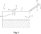
- FIG 1 represents a storage tank of an aqueous solution 2 of an ammonia precursor such as a eutectic solution of urea, comprising a main body 3, a filler neck 4 and a ventilation member 6.
- the tubing of filling opens by a lower internal end downstream in the body.
- the ventilation member 6 opens by an inner lower end upstream in the body.
- the filler neck also has an upstream outer upper end 5 accessible for example from outside the vehicle to introduce the precursor solution into the tank.
- the tubing and the member are independent of each other, disjoint and fully spaced from each other. It is the same especially for their ends contiguous to the tank.
- the ventilation member comprises on its portion extending inside the tank shock-absorbing means 9 adapted to allow it to change its shape under the effect of a bias internal to the tank and having a higher intensity at a predetermined threshold and such that the shape is restored when the solicitation disappears.
- the ventilation member 6 forms a gas communication passage 8 directly between the inside and the outside of the tank 2.
- the ventilation member 6 comprises means represented in FIGS. Figures 2 and 3 .
- FIGS. Figures 2 and 3 represent by way of example a float valve.
- a valve 12 comprises a vertical cylindrical duct 13 of circular section in a plane transverse to its longitudinal axis, this duct being formed by a wall 14 of variable thickness.
- the valve also comprises a ball 110 movably mounted in a housing of the conduit. This valve extends entirely to a level lower than that of the upper wall 7 of the reservoir, in the latter.
- the housing is delimited by a base 18 extending in the lower part of the float valve where the width of the conduit 13 is the largest.
- This base is for example formed by an elongate horizontal bar extending in a direction perpendicular to the plane of the figure. This base prevents the ball from falling into the tank.
- the valve is dimensioned so that when the ball rests on the base, an annular passage is formed between the ball and the wall, around the ball, for the tank air. The valve is then in the open position as on the figure 2 .
- the housing of the ball is defined by a constriction 20 of the wall which limits the rise of the ball in the conduit and forms a seat for the ball in the closed position of the valve, the ball then closing the valve as shown in FIG. the figure 3 .
- a surface annular contact then occurs between the ball and the wall, generating a tight closure of the valve which prohibits the rise of liquid or gas in the ventilation member.
- the valve thus forms detection means 110 of a maximum filling level.
- the ventilation member also comprises a predetermined section forming shock absorbing means 120, the section being located between the float valve 12 and the inner face of the upper wall 7 of the tank, means represented here schematically by a system of springs and formed materially by a corrugated section of the cylindrical tube.
- a predetermined section forming shock absorbing means 120, the section being located between the float valve 12 and the inner face of the upper wall 7 of the tank, means represented here schematically by a system of springs and formed materially by a corrugated section of the cylindrical tube.
- Such annular shape allows an essentially elastic deformation of the section in compression along its vertical longitudinal axis when a compressive stress that exceeds a predetermined threshold is exerted.
- the valve 12 limits the filling of the tank 2 when a level of maximum additive solution is reached. In other words, it allows the ventilation member 6, via an interaction with the liquid present in the tank and represented by its level 24, to stop the gas outlet and thus the filling of the tank.
- the ball 110 located at a distance from the level of the liquid which is lower, rests on the base 18 and allows a flow of air 22 to pass all around it inside.
- valve 12 which is open.
- the shock absorbing means 120 are then in the relaxed position since not solicited by the additive solution.
- the additive solution arrives at the height of the float valve 12.
- the ball 110 arranged to float in the liquid, is then pushed by the liquid additive (represented by its level 24) until it reaches the level of the wall 14 of the tank where the diameter of the pipe is smaller than the diameter of the ball 110.
- the ball has a sufficient density (with reference to the solution) not to be lifted by air during degassing but only by the additive solution during the terminal phase of filling. It can be provided that the shock damping means 210 are then compressed because of the thrust of the ball 110 on the wall 14. The ball thus closes the valve.
- the air can no longer circulate between the ball and the inner wall of the valve.
- the valve being sealed in this configuration, it also prevents the expulsion of liquid outside the tank.
- the liquid additive then rises in the filling pipe 4 to the means 10 for detecting a maximum filling level. This has the advantage of setting a maximum level of filling of the tank.
- the solidified additive then exerts a greater mechanical pressure than that exerted by the liquid solution as seen in FIG. figure 3 .
- the shock absorbing means 9 absorb this pressure by deforming the member 9 which retracts to prevent possible breakage of the inner end of the ventilation member. They also protect the valve against shocks with blocks of frozen solution floating in the liquid solution.
- the float 210 this time has a plane lower face 28 and a conical upper face 26.
- the inner face 19 of the wall of the float valve at the throttle 20 has a complementary frustoconical shape, in particular of the same angle, to that of the upper face 26 of the float.
- the float therefore adopts a shape that allows it to optimize not only its interaction with the liquid but also with the internal face of the valve.
- the shock absorbing means 120 are further formed here by a corrugated tube which forms a cylindrical section of the wall of the valve, above the throttle.
- the ammonia precursor solution 24 pushes the float 210 along the conduit 13 to press against the inner face 19 of the valve 12. This thrust is then improved thanks to the flat underside of the float.
- the upper portion 26 of the float 210 has a complementary shape with the inner wall of the valve. This has the effect of increasing the contact surface between these two parts and thus the sealing of the device.
- the figure 7 represents, with increased references of 100 for the float and shock-damping means, a float valve according to a third embodiment, with shock-absorbing means 220 comprising a telescopic column. It is a set of concentric tubes threaded into each other sealingly and of respective diameters decreasing from the outer tube to the inner tube of the assembly. This set has a variable length thanks to the sliding of each tube with respect to its neighbor or neighbors.
- the float 310 has a frustoconical upper face 27 and a flat lower face 28.
- the lower end 32 of the telescopic column if it is subjected to an upward axial stress having an intensity which exceeds a predetermined threshold, retracts under the effect of the shock towards its fixed upper end 34 in contact on the inner face of the wall 7 of the tank. Then, once the shock has passed, it unfolds again downwards under the effect of gravity.
- the pressure exerted by the additive is absorbed by the column.
- the float has a shape different from those presented in the three embodiments.
- shock-absorbing means may adopt a different form of the embodiments presented above.
- the damping means could extend over the entire height of the ventilation member.
Landscapes
- Engineering & Computer Science (AREA)
- Chemical & Material Sciences (AREA)
- Combustion & Propulsion (AREA)
- Mechanical Engineering (AREA)
- General Engineering & Computer Science (AREA)
- Chemical Kinetics & Catalysis (AREA)
- Health & Medical Sciences (AREA)
- Toxicology (AREA)
- Exhaust Gas After Treatment (AREA)
- Cooling, Air Intake And Gas Exhaust, And Fuel Tank Arrangements In Propulsion Units (AREA)
- Air Bags (AREA)
- Filling Or Discharging Of Gas Storage Vessels (AREA)
Claims (13)
- Tank (2) zur Bevorratung eines Ammoniak-Vorläufers für ein Fahrzeug umfassend ein Belüftungsorgan (6), das eine Wand des Tanks durchquert, dadurch gekennzeichnet, dass das Belüftungsorgan an einem Teil im Inneren des Tanks Stoßdämpfungsmittel (9) umfasst, die imstande sind, die Veränderung einer Form des Organs unter der Einwirkung einer Beanspruchung im Inneren des Tanks einer Stärke größer als ein vorab bestimmter Schwellwert zu gestatten und die Form wiederherzustellen, wenn die Beanspruchung verschwindet.
- Tank (2) nach Anspruch 1, wobei das Belüftungsorgan derart ausgebildet ist, dass eine Länge des Organs sich unter der Einwirkung der Beanspruchung im Inneren des Tanks einer Stärke größer als ein vorab bestimmter Schwellwert verringert und dass die Länge zunimmt, wenn die Beanspruchung verschwindet.
- Tank (2) nach einem der vorhergehenden Ansprüche, wobei das Belüftungsorgan (6) einen elastischen Abschnitt umfasst.
- Tank (2) nach einem der vorhergehenden Ansprüche, wobei das Belüftungsorgan (6) einen gerillten Abschnitt (120) umfasst.
- Tank (2) nach einem der vorhergehenden Ansprüche, wobei das Belüftungsorgan einen teleskopischen Abschnitt (220) umfasst.
- Tank (2) nach einem der vorhergehenden Ansprüche, wobei der Tank einen Füllstutzen (4) umfasst und das Belüftungsorgan (6) so angeordnet ist, dass es mit dem Außenbereich des Tanks unabhängig von dem Füllstutzen kommuniziert.
- Tank (2) nach dem vorhergehenden Anspruch, wobei der Füllstutzen (4) keine eigene Belüftungsleitung umfasst.
- Tank (2) nach einem der vorhergehenden Ansprüche, wobei das Belüftungsorgan (6) angeordnet ist, um den Tank zu verschließen, wenn eine Flüssigkeit einen vorab bestimmten Füllstand in dem Tank erreicht.
- Tank (2) nach einem der vorhergehenden Ansprüche, wobei das Belüftungsorgan (6) ein Schwimmerventil (12) umfasst.
- Tank (2) nach dem vorhergehenden Anspruch, wobei der Schwimmer (110) eine Kugel umfasst.
- Tank (2) nach Anspruch 9, wobei der Schwimmer (210, 310) eine ebene untere Fläche (28) umfasst.
- Tank (2) nach Anspruch 9 oder 11, wobei der Schwimmer (310) eine kegelstumpfförmige obere Fläche (27) umfasst.
- Tank (2) nach einem der vorhergehenden Ansprüche, wobei es sich um einen Tank mit einer Harnstofflösung handelt.
Applications Claiming Priority (2)
| Application Number | Priority Date | Filing Date | Title |
|---|---|---|---|
| FR1563193A FR3046118B1 (fr) | 2015-12-23 | 2015-12-23 | Reservoir de stockage d'un precurseur d'ammoniac |
| PCT/EP2016/082070 WO2017108887A1 (fr) | 2015-12-23 | 2016-12-21 | Réservoir de stockage d'un précurseur d'ammoniac |
Publications (2)
| Publication Number | Publication Date |
|---|---|
| EP3394405A1 EP3394405A1 (de) | 2018-10-31 |
| EP3394405B1 true EP3394405B1 (de) | 2019-11-20 |
Family
ID=55759743
Family Applications (1)
| Application Number | Title | Priority Date | Filing Date |
|---|---|---|---|
| EP16826724.3A Not-in-force EP3394405B1 (de) | 2015-12-23 | 2016-12-21 | Tank zur lagerung eines ammoniakvorläufers |
Country Status (3)
| Country | Link |
|---|---|
| EP (1) | EP3394405B1 (de) |
| FR (1) | FR3046118B1 (de) |
| WO (1) | WO2017108887A1 (de) |
Cited By (1)
| Publication number | Priority date | Publication date | Assignee | Title |
|---|---|---|---|---|
| CN114575974A (zh) * | 2022-03-10 | 2022-06-03 | 山东统亚模塑科技实业有限公司 | 一种尿素箱加注口结构及尿素箱 |
Families Citing this family (1)
| Publication number | Priority date | Publication date | Assignee | Title |
|---|---|---|---|---|
| CN116696523B (zh) * | 2023-05-26 | 2025-11-21 | 东风商用车有限公司 | 一种防加满尿素箱 |
Family Cites Families (3)
| Publication number | Priority date | Publication date | Assignee | Title |
|---|---|---|---|---|
| DE102009011518A1 (de) * | 2009-03-06 | 2010-09-16 | Kautex Textron Gmbh & Co. Kg | Reduktionsmittelbehälter |
| DE102009029375A1 (de) * | 2009-09-11 | 2011-03-24 | Robert Bosch Gmbh | Fahrzeugtank mit Kompensationskörper |
| DE102014007706A1 (de) * | 2014-05-28 | 2015-12-03 | Kautex Textron Gmbh & Co. Kg | Vorratsbehälter in einem Kfz |
-
2015
- 2015-12-23 FR FR1563193A patent/FR3046118B1/fr not_active Expired - Fee Related
-
2016
- 2016-12-21 WO PCT/EP2016/082070 patent/WO2017108887A1/fr not_active Ceased
- 2016-12-21 EP EP16826724.3A patent/EP3394405B1/de not_active Not-in-force
Non-Patent Citations (1)
| Title |
|---|
| None * |
Cited By (1)
| Publication number | Priority date | Publication date | Assignee | Title |
|---|---|---|---|---|
| CN114575974A (zh) * | 2022-03-10 | 2022-06-03 | 山东统亚模塑科技实业有限公司 | 一种尿素箱加注口结构及尿素箱 |
Also Published As
| Publication number | Publication date |
|---|---|
| FR3046118B1 (fr) | 2019-04-19 |
| FR3046118A1 (fr) | 2017-06-30 |
| WO2017108887A1 (fr) | 2017-06-29 |
| EP3394405A1 (de) | 2018-10-31 |
Similar Documents
| Publication | Publication Date | Title |
|---|---|---|
| EP1172306B1 (de) | Entlüftungssystem für Flüssigkeitstank | |
| BE1009778A4 (fr) | Embout de remplissage d'un reservoir a carburant. | |
| EP3394405B1 (de) | Tank zur lagerung eines ammoniakvorläufers | |
| FR2897309A1 (fr) | Systeme de stockage de carburant | |
| EP3169920B1 (de) | Sicherheitsventil | |
| FR2937705A1 (fr) | Reservoir a carburant comprenant un systeme de ventilation equipe d'un separateur liquide/vapeur | |
| WO2017055744A1 (fr) | Cuve étanche et isolante disposée dans un navire | |
| FR2949503A1 (fr) | Reservoir souple pour produit additif | |
| FR3071012A1 (fr) | Injecteur a reduction du volume de fluide | |
| EP3302351B1 (de) | Trinkhalm zum einhalten einer vorbestimmten dosis einer flüssigkeitsbasierten substanz sowie injektionsvorrichtung und verfahren damit | |
| EP2691620B1 (de) | Vorrichtung zur tankbefüllung eines kraftfahrzeugs | |
| EP2958638B1 (de) | Trockenes fallrohr zum einbau in einer feuerschutzanlage mit einem netzwerk von vakuumsprinklern | |
| EP2246221B1 (de) | Go-kart mit elastischen aufpralldämpfenden Mitteln, entsprechende Vorrichtung | |
| EP1880910A1 (de) | Vorrichtung zum Reinigen einer transparenten oder spiegelnden Oberfläche, insbesondere des Scheinwerferglases eines Kraftfahrzeugs | |
| EP3803074B1 (de) | System zur speicherung einer wässrigen lösung für ein kraftfahrzeug | |
| EP1746380B1 (de) | Kraftstoffbehälter mit einer Vorrichtung zum Entleeren im Notfall | |
| FR2963596A1 (fr) | Reservoir de liquide lave-vitre d'un vehicule automobile | |
| FR2795801A1 (fr) | Soupape de surete pour reservoir contenant un fluide liquide sous pression tel que du gpl | |
| FR2571132A1 (fr) | Bourre amortissante pour cartouches de chasse | |
| FR3148013A1 (fr) | Bouchon pour évent de délestage | |
| FR2938797A1 (fr) | Tete de tubulure comportant un coussin absorbeur de chocs | |
| FR2741137A1 (fr) | Dispositif de blocage de securite pour canalisations transportant des fluides gazeux | |
| FR3061768A1 (fr) | Dispositif d'evacuation de douilles | |
| EP3342617B1 (de) | Rohrleitungskopf und lagervorrichtung, die einen solchen kopf umfasst | |
| FR2556295A1 (fr) | Dispositif d'absorption d'energie pour le montage d'un pare-chocs sur un vehicule automobile |
Legal Events
| Date | Code | Title | Description |
|---|---|---|---|
| STAA | Information on the status of an ep patent application or granted ep patent |
Free format text: STATUS: UNKNOWN |
|
| STAA | Information on the status of an ep patent application or granted ep patent |
Free format text: STATUS: THE INTERNATIONAL PUBLICATION HAS BEEN MADE |
|
| PUAI | Public reference made under article 153(3) epc to a published international application that has entered the european phase |
Free format text: ORIGINAL CODE: 0009012 |
|
| STAA | Information on the status of an ep patent application or granted ep patent |
Free format text: STATUS: REQUEST FOR EXAMINATION WAS MADE |
|
| 17P | Request for examination filed |
Effective date: 20180719 |
|
| AK | Designated contracting states |
Kind code of ref document: A1 Designated state(s): AL AT BE BG CH CY CZ DE DK EE ES FI FR GB GR HR HU IE IS IT LI LT LU LV MC MK MT NL NO PL PT RO RS SE SI SK SM TR |
|
| AX | Request for extension of the european patent |
Extension state: BA ME |
|
| RIN1 | Information on inventor provided before grant (corrected) |
Inventor name: GUILLERME, HERVE Inventor name: LAHRAICHI, SAID |
|
| DAV | Request for validation of the european patent (deleted) | ||
| DAX | Request for extension of the european patent (deleted) | ||
| GRAP | Despatch of communication of intention to grant a patent |
Free format text: ORIGINAL CODE: EPIDOSNIGR1 |
|
| STAA | Information on the status of an ep patent application or granted ep patent |
Free format text: STATUS: GRANT OF PATENT IS INTENDED |
|
| INTG | Intention to grant announced |
Effective date: 20190624 |
|
| RAP1 | Party data changed (applicant data changed or rights of an application transferred) |
Owner name: PLASTIC OMNIUM ADVANCED INNOVATION AND RESEARCH |
|
| GRAS | Grant fee paid |
Free format text: ORIGINAL CODE: EPIDOSNIGR3 |
|
| GRAA | (expected) grant |
Free format text: ORIGINAL CODE: 0009210 |
|
| STAA | Information on the status of an ep patent application or granted ep patent |
Free format text: STATUS: THE PATENT HAS BEEN GRANTED |
|
| AK | Designated contracting states |
Kind code of ref document: B1 Designated state(s): AL AT BE BG CH CY CZ DE DK EE ES FI FR GB GR HR HU IE IS IT LI LT LU LV MC MK MT NL NO PL PT RO RS SE SI SK SM TR |
|
| REG | Reference to a national code |
Ref country code: GB Ref legal event code: FG4D Free format text: NOT ENGLISH |
|
| REG | Reference to a national code |
Ref country code: CH Ref legal event code: EP |
|
| REG | Reference to a national code |
Ref country code: IE Ref legal event code: FG4D Free format text: LANGUAGE OF EP DOCUMENT: FRENCH |
|
| REG | Reference to a national code |
Ref country code: DE Ref legal event code: R096 Ref document number: 602016024841 Country of ref document: DE |
|
| REG | Reference to a national code |
Ref country code: AT Ref legal event code: REF Ref document number: 1204452 Country of ref document: AT Kind code of ref document: T Effective date: 20191215 |
|
| REG | Reference to a national code |
Ref country code: NL Ref legal event code: MP Effective date: 20191120 |
|
| REG | Reference to a national code |
Ref country code: LT Ref legal event code: MG4D |
|
| PG25 | Lapsed in a contracting state [announced via postgrant information from national office to epo] |
Ref country code: LV Free format text: LAPSE BECAUSE OF FAILURE TO SUBMIT A TRANSLATION OF THE DESCRIPTION OR TO PAY THE FEE WITHIN THE PRESCRIBED TIME-LIMIT Effective date: 20191120 Ref country code: SE Free format text: LAPSE BECAUSE OF FAILURE TO SUBMIT A TRANSLATION OF THE DESCRIPTION OR TO PAY THE FEE WITHIN THE PRESCRIBED TIME-LIMIT Effective date: 20191120 Ref country code: FI Free format text: LAPSE BECAUSE OF FAILURE TO SUBMIT A TRANSLATION OF THE DESCRIPTION OR TO PAY THE FEE WITHIN THE PRESCRIBED TIME-LIMIT Effective date: 20191120 Ref country code: BG Free format text: LAPSE BECAUSE OF FAILURE TO SUBMIT A TRANSLATION OF THE DESCRIPTION OR TO PAY THE FEE WITHIN THE PRESCRIBED TIME-LIMIT Effective date: 20200220 Ref country code: LT Free format text: LAPSE BECAUSE OF FAILURE TO SUBMIT A TRANSLATION OF THE DESCRIPTION OR TO PAY THE FEE WITHIN THE PRESCRIBED TIME-LIMIT Effective date: 20191120 Ref country code: GR Free format text: LAPSE BECAUSE OF FAILURE TO SUBMIT A TRANSLATION OF THE DESCRIPTION OR TO PAY THE FEE WITHIN THE PRESCRIBED TIME-LIMIT Effective date: 20200221 Ref country code: NO Free format text: LAPSE BECAUSE OF FAILURE TO SUBMIT A TRANSLATION OF THE DESCRIPTION OR TO PAY THE FEE WITHIN THE PRESCRIBED TIME-LIMIT Effective date: 20200220 Ref country code: NL Free format text: LAPSE BECAUSE OF FAILURE TO SUBMIT A TRANSLATION OF THE DESCRIPTION OR TO PAY THE FEE WITHIN THE PRESCRIBED TIME-LIMIT Effective date: 20191120 |
|
| PG25 | Lapsed in a contracting state [announced via postgrant information from national office to epo] |
Ref country code: HR Free format text: LAPSE BECAUSE OF FAILURE TO SUBMIT A TRANSLATION OF THE DESCRIPTION OR TO PAY THE FEE WITHIN THE PRESCRIBED TIME-LIMIT Effective date: 20191120 Ref country code: IS Free format text: LAPSE BECAUSE OF FAILURE TO SUBMIT A TRANSLATION OF THE DESCRIPTION OR TO PAY THE FEE WITHIN THE PRESCRIBED TIME-LIMIT Effective date: 20200320 Ref country code: RS Free format text: LAPSE BECAUSE OF FAILURE TO SUBMIT A TRANSLATION OF THE DESCRIPTION OR TO PAY THE FEE WITHIN THE PRESCRIBED TIME-LIMIT Effective date: 20191120 |
|
| PG25 | Lapsed in a contracting state [announced via postgrant information from national office to epo] |
Ref country code: AL Free format text: LAPSE BECAUSE OF FAILURE TO SUBMIT A TRANSLATION OF THE DESCRIPTION OR TO PAY THE FEE WITHIN THE PRESCRIBED TIME-LIMIT Effective date: 20191120 |
|
| REG | Reference to a national code |
Ref country code: DE Ref legal event code: R119 Ref document number: 602016024841 Country of ref document: DE |
|
| PG25 | Lapsed in a contracting state [announced via postgrant information from national office to epo] |
Ref country code: PT Free format text: LAPSE BECAUSE OF FAILURE TO SUBMIT A TRANSLATION OF THE DESCRIPTION OR TO PAY THE FEE WITHIN THE PRESCRIBED TIME-LIMIT Effective date: 20200412 Ref country code: EE Free format text: LAPSE BECAUSE OF FAILURE TO SUBMIT A TRANSLATION OF THE DESCRIPTION OR TO PAY THE FEE WITHIN THE PRESCRIBED TIME-LIMIT Effective date: 20191120 Ref country code: DK Free format text: LAPSE BECAUSE OF FAILURE TO SUBMIT A TRANSLATION OF THE DESCRIPTION OR TO PAY THE FEE WITHIN THE PRESCRIBED TIME-LIMIT Effective date: 20191120 Ref country code: RO Free format text: LAPSE BECAUSE OF FAILURE TO SUBMIT A TRANSLATION OF THE DESCRIPTION OR TO PAY THE FEE WITHIN THE PRESCRIBED TIME-LIMIT Effective date: 20191120 Ref country code: CZ Free format text: LAPSE BECAUSE OF FAILURE TO SUBMIT A TRANSLATION OF THE DESCRIPTION OR TO PAY THE FEE WITHIN THE PRESCRIBED TIME-LIMIT Effective date: 20191120 Ref country code: ES Free format text: LAPSE BECAUSE OF FAILURE TO SUBMIT A TRANSLATION OF THE DESCRIPTION OR TO PAY THE FEE WITHIN THE PRESCRIBED TIME-LIMIT Effective date: 20191120 |
|
| REG | Reference to a national code |
Ref country code: CH Ref legal event code: PL |
|
| REG | Reference to a national code |
Ref country code: AT Ref legal event code: MK05 Ref document number: 1204452 Country of ref document: AT Kind code of ref document: T Effective date: 20191120 |
|
| REG | Reference to a national code |
Ref country code: BE Ref legal event code: MM Effective date: 20191231 |
|
| PG25 | Lapsed in a contracting state [announced via postgrant information from national office to epo] |
Ref country code: SM Free format text: LAPSE BECAUSE OF FAILURE TO SUBMIT A TRANSLATION OF THE DESCRIPTION OR TO PAY THE FEE WITHIN THE PRESCRIBED TIME-LIMIT Effective date: 20191120 Ref country code: MC Free format text: LAPSE BECAUSE OF FAILURE TO SUBMIT A TRANSLATION OF THE DESCRIPTION OR TO PAY THE FEE WITHIN THE PRESCRIBED TIME-LIMIT Effective date: 20191120 Ref country code: SK Free format text: LAPSE BECAUSE OF FAILURE TO SUBMIT A TRANSLATION OF THE DESCRIPTION OR TO PAY THE FEE WITHIN THE PRESCRIBED TIME-LIMIT Effective date: 20191120 |
|
| PLBE | No opposition filed within time limit |
Free format text: ORIGINAL CODE: 0009261 |
|
| STAA | Information on the status of an ep patent application or granted ep patent |
Free format text: STATUS: NO OPPOSITION FILED WITHIN TIME LIMIT |
|
| 26N | No opposition filed |
Effective date: 20200821 |
|
| PG25 | Lapsed in a contracting state [announced via postgrant information from national office to epo] |
Ref country code: DE Free format text: LAPSE BECAUSE OF NON-PAYMENT OF DUE FEES Effective date: 20200701 Ref country code: IE Free format text: LAPSE BECAUSE OF NON-PAYMENT OF DUE FEES Effective date: 20191221 Ref country code: LU Free format text: LAPSE BECAUSE OF NON-PAYMENT OF DUE FEES Effective date: 20191221 |
|
| PG25 | Lapsed in a contracting state [announced via postgrant information from national office to epo] |
Ref country code: SI Free format text: LAPSE BECAUSE OF FAILURE TO SUBMIT A TRANSLATION OF THE DESCRIPTION OR TO PAY THE FEE WITHIN THE PRESCRIBED TIME-LIMIT Effective date: 20191120 Ref country code: BE Free format text: LAPSE BECAUSE OF NON-PAYMENT OF DUE FEES Effective date: 20191231 Ref country code: AT Free format text: LAPSE BECAUSE OF FAILURE TO SUBMIT A TRANSLATION OF THE DESCRIPTION OR TO PAY THE FEE WITHIN THE PRESCRIBED TIME-LIMIT Effective date: 20191120 Ref country code: CH Free format text: LAPSE BECAUSE OF NON-PAYMENT OF DUE FEES Effective date: 20191231 Ref country code: LI Free format text: LAPSE BECAUSE OF NON-PAYMENT OF DUE FEES Effective date: 20191231 Ref country code: PL Free format text: LAPSE BECAUSE OF FAILURE TO SUBMIT A TRANSLATION OF THE DESCRIPTION OR TO PAY THE FEE WITHIN THE PRESCRIBED TIME-LIMIT Effective date: 20191120 |
|
| PG25 | Lapsed in a contracting state [announced via postgrant information from national office to epo] |
Ref country code: IT Free format text: LAPSE BECAUSE OF FAILURE TO SUBMIT A TRANSLATION OF THE DESCRIPTION OR TO PAY THE FEE WITHIN THE PRESCRIBED TIME-LIMIT Effective date: 20191120 |
|
| PG25 | Lapsed in a contracting state [announced via postgrant information from national office to epo] |
Ref country code: CY Free format text: LAPSE BECAUSE OF FAILURE TO SUBMIT A TRANSLATION OF THE DESCRIPTION OR TO PAY THE FEE WITHIN THE PRESCRIBED TIME-LIMIT Effective date: 20191120 |
|
| PG25 | Lapsed in a contracting state [announced via postgrant information from national office to epo] |
Ref country code: MT Free format text: LAPSE BECAUSE OF FAILURE TO SUBMIT A TRANSLATION OF THE DESCRIPTION OR TO PAY THE FEE WITHIN THE PRESCRIBED TIME-LIMIT Effective date: 20191120 Ref country code: HU Free format text: LAPSE BECAUSE OF FAILURE TO SUBMIT A TRANSLATION OF THE DESCRIPTION OR TO PAY THE FEE WITHIN THE PRESCRIBED TIME-LIMIT; INVALID AB INITIO Effective date: 20161221 |
|
| GBPC | Gb: european patent ceased through non-payment of renewal fee |
Effective date: 20201221 |
|
| PG25 | Lapsed in a contracting state [announced via postgrant information from national office to epo] |
Ref country code: GB Free format text: LAPSE BECAUSE OF NON-PAYMENT OF DUE FEES Effective date: 20201221 |
|
| PG25 | Lapsed in a contracting state [announced via postgrant information from national office to epo] |
Ref country code: TR Free format text: LAPSE BECAUSE OF FAILURE TO SUBMIT A TRANSLATION OF THE DESCRIPTION OR TO PAY THE FEE WITHIN THE PRESCRIBED TIME-LIMIT Effective date: 20191120 |
|
| PG25 | Lapsed in a contracting state [announced via postgrant information from national office to epo] |
Ref country code: MK Free format text: LAPSE BECAUSE OF FAILURE TO SUBMIT A TRANSLATION OF THE DESCRIPTION OR TO PAY THE FEE WITHIN THE PRESCRIBED TIME-LIMIT Effective date: 20191120 |
|
| P01 | Opt-out of the competence of the unified patent court (upc) registered |
Effective date: 20230515 |
|
| PGFP | Annual fee paid to national office [announced via postgrant information from national office to epo] |
Ref country code: FR Payment date: 20231229 Year of fee payment: 8 |
|
| PG25 | Lapsed in a contracting state [announced via postgrant information from national office to epo] |
Ref country code: FR Free format text: LAPSE BECAUSE OF NON-PAYMENT OF DUE FEES Effective date: 20241231 |