EP3394452B1 - Verbindungseinrichtung - Google Patents
Verbindungseinrichtung Download PDFInfo
- Publication number
- EP3394452B1 EP3394452B1 EP16825345.8A EP16825345A EP3394452B1 EP 3394452 B1 EP3394452 B1 EP 3394452B1 EP 16825345 A EP16825345 A EP 16825345A EP 3394452 B1 EP3394452 B1 EP 3394452B1
- Authority
- EP
- European Patent Office
- Prior art keywords
- connection device
- decoupling
- connection
- tube
- holding elements
- Prior art date
- Legal status (The legal status is an assumption and is not a legal conclusion. Google has not performed a legal analysis and makes no representation as to the accuracy of the status listed.)
- Active
Links
Images

Classifications
-
- F—MECHANICAL ENGINEERING; LIGHTING; HEATING; WEAPONS; BLASTING
- F16—ENGINEERING ELEMENTS AND UNITS; GENERAL MEASURES FOR PRODUCING AND MAINTAINING EFFECTIVE FUNCTIONING OF MACHINES OR INSTALLATIONS; THERMAL INSULATION IN GENERAL
- F16L—PIPES; JOINTS OR FITTINGS FOR PIPES; SUPPORTS FOR PIPES, CABLES OR PROTECTIVE TUBING; MEANS FOR THERMAL INSULATION IN GENERAL
- F16L55/00—Devices or appurtenances for use in, or in connection with, pipes or pipe systems
- F16L55/04—Devices damping pulsations or vibrations in fluids
-
- F—MECHANICAL ENGINEERING; LIGHTING; HEATING; WEAPONS; BLASTING
- F04—POSITIVE - DISPLACEMENT MACHINES FOR LIQUIDS; PUMPS FOR LIQUIDS OR ELASTIC FLUIDS
- F04D—NON-POSITIVE-DISPLACEMENT PUMPS
- F04D19/00—Axial-flow pumps
- F04D19/02—Multi-stage pumps
- F04D19/04—Multi-stage pumps specially adapted to the production of a high vacuum, e.g. molecular pumps
- F04D19/042—Turbomolecular vacuum pumps
-
- F—MECHANICAL ENGINEERING; LIGHTING; HEATING; WEAPONS; BLASTING
- F04—POSITIVE - DISPLACEMENT MACHINES FOR LIQUIDS; PUMPS FOR LIQUIDS OR ELASTIC FLUIDS
- F04D—NON-POSITIVE-DISPLACEMENT PUMPS
- F04D29/00—Details, component parts, or accessories
- F04D29/60—Mounting; Assembling; Disassembling
- F04D29/601—Mounting; Assembling; Disassembling specially adapted for elastic fluid pumps
-
- F—MECHANICAL ENGINEERING; LIGHTING; HEATING; WEAPONS; BLASTING
- F04—POSITIVE - DISPLACEMENT MACHINES FOR LIQUIDS; PUMPS FOR LIQUIDS OR ELASTIC FLUIDS
- F04D—NON-POSITIVE-DISPLACEMENT PUMPS
- F04D29/00—Details, component parts, or accessories
- F04D29/66—Combating cavitation, whirls, noise, vibration or the like; Balancing
- F04D29/661—Combating cavitation, whirls, noise, vibration or the like; Balancing especially adapted for elastic fluid pumps
- F04D29/668—Combating cavitation, whirls, noise, vibration or the like; Balancing especially adapted for elastic fluid pumps damping or preventing mechanical vibrations
Definitions
- Connecting device for connecting a first pipe end that can be connected to a vacuum pump to a second pipe end that can be connected to a recipient.
- the problem is that vibrations are transmitted from the vacuum pump to the chamber to be evacuated, particularly due to the rotor rotation. These can affect processes or measurements carried out in the chamber being evacuated or a device connected to the chamber being evacuated. For example, electron microscopes are extremely susceptible to vibration.
- a damping element between a pipe end that can be connected to the vacuum pump and a pipe end that can be connected to the chamber to be evacuated.
- This has, for example, a flexible metal bellows to ensure vacuum tightness.
- the metal bellows is surrounded, for example, by an elastic damping element.
- a connecting element is known. This has two pipe pieces, one of the pipe pieces being firmly connected to the pipe end that can be connected to the vacuum pump and the second pipe piece being firmly connected to the pipe end that can be connected to the chamber to be evacuated. Two annular elastomer seals are provided between the two pipe ends. These are surrounded by a clamp-like element, which also has an inward-pointing web arranged between the two sealing elements. When the vacuum pump is not in operation, the two pipe sections are pushed apart by the elastomer rings and are mechanically connected by the clamp surrounding the pipe sections.
- This mechanical connection which would also transmit vibrations, is released by the vacuum generated in such a way that the two elastomer rings are pressed together and the mechanical connection of the two pipe sections is released via the clasp.
- this connection device has the particular disadvantage that the solution to the mechanical connection is not clearly defined. This depends, for example, on the level of vacuum generated. Furthermore, the elastic properties of the sealing rings change, so that they have to be replaced regularly. There is also a risk that the connecting element could leak if there is a lateral load on the pump.
- a connecting device for connecting a first pipe end that can be connected to a vacuum pump to a chamber to be evacuated connectable second pipe end with the features of the preamble of claim 1 is out EP 2 410 184 known.
- the object of the invention is to create a connecting device for connecting a first pipe element that can be connected to a vacuum pump to a second pipe element that can be connected to a chamber to be evacuated, which enables good mechanical decoupling with a high level of safety at the same time.
- the connecting device serves to connect a first pipe end that can be connected to a vacuum pump or a turbomolecular pump to a second pipe end, the second pipe end being connectable to a chamber to be evacuated.
- the first pipe element can also be part of the vacuum pump or the inlet flange of the vacuum pump.
- the second pipe element can also be part of the chamber to be evacuated.
- the connecting element has a tubular element for fluidly connecting the vacuum pump to the chamber to be evacuated.
- the pipe element creates the vacuum connection required for evacuation.
- the tubular element therefore has a connecting element on each side or is connected to a connecting element.
- the two connecting elements serve to connect the pipe element to one of the two pipe ends.
- At least one of the two connecting elements is designed in such a way that it is only suitable for transmitting torque.
- no axial forces i.e. forces running in the longitudinal direction of the tubular element, can be transmitted during operation by the connecting element. This ensures that the transmission of vibrations from the vacuum pump to the chamber to be evacuated or from the first pipe end to the second pipe end is not possible or is at least strongly damped.
- moments can be transmitted by the at least one connecting element. These are moments around the longitudinal axis of the tubular element which occur particularly in the event of a crash but also when the vacuum pump is started up or braked. This ensures appropriate security.
- Both connecting elements are preferably designed in this way. According to the invention, a decoupling element is provided.
- the decoupling element serves to mechanically decouple the at least one connecting element, which is suitable exclusively for transmitting torque, from the corresponding pipe end.
- the decoupling element serves to mechanically decouple both connecting elements, provided that both connecting elements are only suitable for transmitting torque.
- the decoupling element generates an axial force that counteracts the force generated by the vacuum during operation.
- the axial force generated by the decoupling element is greater than the counterforce generated by the vacuum. This creates a mechanical connection between the two pipe ends, so that the moments that occur can be transferred well.
- an axial final coupling occurs during operation due to a balance of forces between the force generated by the decoupling element and the force generated by the vacuum, so that the transmission of vibrations is at least greatly reduced.
- the decoupling element has at least one fluid chamber filled with compressible fluid.
- the fluid is in particular gas and particularly preferably air.
- the decoupling element preferably has at least two holding elements.
- the two holding elements can each be firmly connected to one of the pipe ends. Due to the firm connection between the holding elements and the respective pipe ends, in particular from the pipe end that can be connected to the vacuum pump to the one Holding element and forces and moments are transmitted from the other holding element to the pipe end that can be connected to the chamber to be evacuated. It is also possible for at least one of the two holding elements to be formed in one piece with the corresponding pipe end or for a non-detachable connection to be made.
- the fluid chamber is preferably arranged between the two holding elements. Increasing the pressure in the fluid chamber causes the two holding elements to be pushed apart.
- the decoupling element further has an outer element, in particular completely surrounding the tubular element.
- the outer element is preferably designed in a ring shape.
- the outer element covers the two holding elements in the axial direction, whereby the outer element can also be firmly connected to one of the two holding elements or be formed in one piece. It is preferred that the outer element is not firmly connected to either of the two holding elements.
- the outer element is thus movable in the axial direction in particular to one of the two holding elements and preferably to both holding elements, or a corresponding axial relative movement is made possible.
- a first sealing element is preferably arranged between the outer element and the holding element which is displaceable relative thereto.
- This is in particular an elastic sealing element, in particular a sealing ring surrounding the holding element. Essentially no forces, in particular essentially no vibrations, are transmitted through this.
- a second sealing element is provided, which is arranged between the outer element and the second holding element which is displaceable in particular in the axial direction relative to the outer element.
- the second sealing element is preferably designed corresponding to the first sealing element.
- a sealing element is arranged between the tubular element and the two holding elements. This is preferably designed in accordance with the first sealing element, so that essentially no forces or vibrations are transmitted through it.
- the fluid chamber is delimited by the outer element, the tubular element and the two holding elements.
- the limitation is achieved in particular by an inside of the outer element and an opposite outside of the tubular element.
- the holding elements delimit the fluid chamber in particular by their end faces.
- the fluid chamber is annular and in particular completely surrounds the tubular element. This allows a uniform force to be generated in the axial direction. A change in the force, particularly in the circumferential direction of the preferably annular fluid chamber, is thereby avoided.
- the fluid chamber is connected to a supply channel.
- the supply channel is used to supply fluid, in particular gas.
- a valve is preferably arranged in the feed channel. This makes it possible to easily vary the pressure in the fluid chamber and adapt it to an operating condition. This results in decoupling during operation, so that essentially no vibrations are transmitted from the vacuum pump to the chamber to be evacuated.
- the outer element which is particularly annular, is firmly connected to the tubular element via a web element. This can be done, for example, to simplify assembly using a screw connection. It is also possible to design the tubular element and the outer element in one piece.
- the decoupling element has two fluid chambers. These are in particular one behind the other in the axial direction arranged so that each of the fluid chambers essentially acts on one of the two holding elements. It is particularly preferred that the pressure of the two fluid chambers can be adjusted separately from one another. For this purpose, it is preferably provided that a channel for supplying and discharging compressible fluid such as gas is provided for each fluid chamber and that a valve is preferably arranged in each channel.
- the at least one transmission element suitable for transmitting torque is designed such that axially arranged lugs are provided which protrude into recesses.
- the approaches are provided on the connecting element and the recesses on the holding element.
- the lugs provided on the connecting element point into the recesses provided on the holding element.
- the approaches could also be provided on the connecting element.
- the cross section of the recesses is larger than the cross section of the lugs. This ensures that no moments and therefore no vibrations are transmitted during normal operation.
- Both connecting elements are preferably designed as described above and are advantageously further developed.
- the pressure provided in the at least one fluid chamber initially creates a connection in the axial direction between the two pipe ends between which the connecting element is arranged. This is done in particular by the fact that, in a preferred embodiment, the approaches of the connecting elements rest on the bottom of the corresponding recesses. As soon as a vacuum is generated by the vacuum pump, this creates a axial counterforce that counteracts the axial force generated by the pressure in the at least one fluid chamber. This causes the mechanical connection to be released and thus decoupled.
- a marking in order to be able to easily determine from the outside whether decoupling has occurred at the set vacuum and the set pressure in the at least one fluid chamber.
- a marking can be provided on the outer element and/or at least one of the holding elements.
- the connecting device serves to connect a first pipe end 10, which is connected in particular to a vacuum pump, to a second pipe end 12, which is connected in particular to a chamber to be evacuated.
- a pipe element 14 is provided for fluidic connection. This is connected to a connecting ring 16 at its two opposite ends, in particular via fastening screws (not shown).
- the ring 16 has a centering ring 18 with a seal.
- the centering ring 18 is arranged between flanges 20 of the two pipe ends 10, 12 and flanges 22 opposite them.
- the flanges 22 are each part of two holding elements 24.
- the holding elements 24 are each annular and surround the tube element 14.
- the two holding elements 24 are, for example, firmly connected to the first tube end 10 or to the second tube end 12 via clamps 27 and are therefore rigidly connected.
- the tubular element 14 is connected to the two tubular elements 10, 12 via connecting elements 26, the two holding elements 24 also being components of the connecting elements 26.
- the connection is made in such a way that moments can be transmitted through the connection, particularly in the event of a failure of the vacuum pump. These are the moments that occur around a longitudinal axis 28.
- the holding elements 24 ( Fig. 2 ) has a radially inwardly pointing projection 30.
- the approach 30 has recesses 32 into which approaches 34 ( Fig. 1 ) protrude.
- the approaches 34 are screw heads.
- the diameter of the recesses 32 is slightly larger than the diameter of the screw heads 34.
- the connecting device has a decoupling element 36.
- This serves to mechanically decouple the two connecting elements 26 from the two pipe ends 10, 12, so that no axial forces, ie forces that run in the direction of the longitudinal axis 28, can be transmitted or their transmission is strongly damped. In this respect, there is no or very little transmission of vibrations from the vacuum pump to the chamber to be evacuated and the components connected to it.
- the decoupling element 36 has an annular outer element 38.
- the outer element 38 can be displaced in the axial direction, ie in the longitudinal direction 28, relative to the two holding elements 24, which are also annular. Between the outer element 38 and an annular sealing element 40 is arranged in each of the two holding elements 24.
- annular sealing element 42 is optionally provided for sealing against the tubular element 14.
- annular sealing element 42 is optionally provided for sealing against the tubular element 14.
- the outer element 38 of the decoupling element 36 is connected to the tubular element 14 via a web element 44. This is a fixed connection, with the web element 44 being connected to a web-shaped extension 46 of the tubular element 14, for example by screwing. An axial movement of the tubular element 14 always causes an axial movement of the outer element 38.
- two fluid chambers 48, 50 are formed, which are in the in Fig. 1 illustrated embodiment are fluidly connected to one another via a connecting channel 52 provided in the webs 44, 46.
- the fluid chambers 48, 50 are thus delimited by an inside of the outer element 38, end faces of the two holding elements 24 and an outside of the tubular element 14.
- the fluid chambers 48, 50 have a supply channel 54 in which a valve 56 is arranged.
- a fluid, in particular compressed air, can thus be supplied or removed from the two fluid chambers 48, 50 via the valve 56.
- the pressure in the fluid chambers 48, 50 must be adjusted to the vacuum. According to the invention, this is possible in a simple manner by supplying or removing compressed air through the supply channel 54.
- a marking is provided on the outer ring 38 and/or one of the two holding elements 24, so that the position of the outer ring 38 and thus also of the tubular element 14 relative to the holding elements 24 can be read in a simple manner. This allows the required pressure in the fluid chambers 48, 50 to be determined in a simple manner in order to ensure axial decoupling.
- the outer ring 38 is formed in one piece with the tubular element 14.
- the connection is made via a solid web 58.
- the web 58 also has no bores for connecting the two fluid chambers 48, 50. Rather, a feed channel 60 is provided for each fluid chamber 48, 50, in which a valve 62 is arranged. This makes it possible to adjust the pressure in the two fluid chambers 48, 50 independently of one another, so that fine adjustment is possible.
- two markings are provided, with one marking indicating the relative position between the outer element 38 and an in Fig. 1 upper holding element 24 and the second marking the relative position to the in Fig. 3 lower holding element 24 illustrated.
Landscapes
- Engineering & Computer Science (AREA)
- General Engineering & Computer Science (AREA)
- Mechanical Engineering (AREA)
- Compressors, Vaccum Pumps And Other Relevant Systems (AREA)
- Flanged Joints, Insulating Joints, And Other Joints (AREA)
- Pipe Accessories (AREA)
- Non-Positive Displacement Air Blowers (AREA)
- Quick-Acting Or Multi-Walled Pipe Joints (AREA)
Description
- Verbindungseinrichtung zum Verbinden eines mit einer Vakuumpumpe verbindbaren ersten Rohrendes mit einem mit einem rezipientenverbindbaren zweiten Rohrende.
- Beim Verbinden einer Vakuumpumpe wie beispielsweise einer Turbomolekularpumpe mit einer zu evakuierenden Kammer besteht die Problematik, dass von der Vakuumpumpe insbesondere aufgrund der Rotordrehung Schwingungen auf die zu evakuierende Kammer übertragen werden. Diese können Prozesse oder Messungen, die in der zu evakuierenden Kammer oder einer mit der zu evakuierenden Kammer verbundenen Einrichtung durchgeführt werden, beeinträchtigen. Beispielsweise sind Elektronenmikrokope äußerst schwingungsanfällig.
- Zur Dämpfung der von der Vakuumpumpe an die zu evakuierende Kammer übertragenen Schwingungen ist es bekannt zwischen einem mit der Vakuumpumpe verbindbaren Rohrende und einem mit der zu evakuierenden Kammer verbindbaren Rohrende ein Dämpfungselement vorzusehen. Dieses weist beispielsweise einen flexiblen Metallbalg auf, um die Vakuumdichtigkeit sicher zu stellen. Der Metallbalg ist beispielsweise von einem elastischen Dämpfungselement umgeben. Bei einem Ausfall der Pumpe, wie beispielsweise einem Blockieren des Rotors können von einem derartigen Dämpfungselement jedoch die Auftretenden Kräfte und Momente nicht aufgenommen bzw. nicht übertragen werden. Dies kann zu einer vollständigen Zerstörung des Dämpfungselements und damit dazu führen, dass die Pumpe sich vollständig vom Dämpfungselement bzw. der zu evakuierenden Kammer löst. Dies stellt aufgrund der hohen kinetischen Energie des schnelldrehenden Rotors ein erhebliches Gefahrenpotential dar.
- Des Weiteren ist aus
EP 2 410 184 ein Verbindungselement bekannt. Dieses weist zwei Rohrstücke auf, wobei eines der Rohrstücke fest mit dem mit der Vakuumpumpe verbindbaren Rohrende und das zweite Rohrstück fest mit dem mit der zu evakuierenden Kammer verbindbaren Rohrende verbunden ist. Zwischen den beiden Rohrenden sind zwei ringförmige Elastomerdichtungen vorgesehen. Diese sind von einem klammerartigen Element umgeben, das ferner einen nach innen weisenden zwischen den beiden Dichtelementen angeordneten Steg aufweist. Wenn die Vakuumpumpe nicht im Betrieb ist, werden die beiden Rohrstücke durch die Eleastomerringe auseinandergedrückt und durch die die Rohrstücke umgebende Spange mechanisch verbunden. Diese mechanische Verbindung, die auch Schwingungen übertragen würde, wird durch das erzeugte Vakuum dahingehend gelöst, dass die beiden Elastomerringe zusammengedrückt werden und hierdurch die mechanische Verbindung der beiden Rohrstücke über die Spange gelöst wird. Diese Verbindungseinrichtng weist jedoch insbesondere den Nachteil auf, dass die Lösung der mechanischen Verbindung nicht klar definiert ist. Diese hängt beispielsweise von der Höhe des erzeugten Vakuums ab. Ferner verändern sich die Elastizitäteigenschaften der Dichtringe, so dass diese regelmäßig erneuert werden müssen. Ebenso besteht die Gefahr, dass bei einer Querbelastung auf die Pumpe das Verbindungselement undicht werden kann. - Eine Verbindungseinrichtung zum Verbinden eines mit einer Vakuumpumpe verbindbaren ersten Rohrendes mit einem mit einer zu evakuierenden Kammer verbindbaren zweiten Rohrende mit den Merkmalen des Oberbegriffs des Anspruchs 1 ist aus
EP 2 410 184 bekannt. - Aufgabe der Erfindung ist es, eine Verbindungseinrichtung zum Verbinden eines mit einer Vakuumpumpe verbindbaren ersten Rohrelements mit einem mit einer zu evakuierenden Kammer verbindbaren zweiten Rohrelement zu schaffen, mit dem eine gute mechanische Entkopplung bei gleichzeitig hoher Sicherheit möglich ist.
- Die Lösung der Aufgabe erfolgt erfindungsgemäß durch eine Verbindungseinrichtung gemäß Anspruch 1.
- Die Verbindungseinrichtung dient dazu, ein erstes mit einer Vakuumpumpe oder eine Turbomolekularpumpe verbindbaren Rohrendes mit einem zweiten Rohrende zu verbinden, wobei das zweite Rohrende mit einer zu evakuierenden Kammer verbindbar ist. Hierbei kann das erste Rohrelement auch Teil der Vakuumpumpe bzw. auch des Einlassflansches der Vakuumpumpe sein. Entsprechend kann das zweite Rohrelement auch Teil der zu evakuierenden Kammer sein. Das Verbindungselement weist erfindungsgemäß ein Rohrelement zur fluidischen Verbindung der Vakuumpumpe mit der zu evakuierenden Kammer auf. Durch das Rohrelement ist die zur Evakuierung erforderliche Vakuumverbindung geschaffen. Das Rohrelement weist damit an jeder Seite ein Verbindungselement auf, bzw. ist mit einem Verbindungselement verbunden. Die beiden Verbindungselemente dienen zum Verbinden des Rohrelements mit jeweils einem der beiden Rohrenden. Zumindest eines der beiden Verbindungselemente ist derart ausgebildet, dass es ausschließlich zur Übertragung von Momenten geeignet ist. Insbesondere können somit im Betrieb durch das Verbindungselement keine Axialkräfte, das heißt in Längsrichtung des Rohrelements verlaufende Kräfte, übertragen werden. Hierdurch ist gewährleistet, dass die Übertragung von Schwingungen von der Vakuumpumpe auf die zu evakuierende Kammer bzw. vom ersten Rohrende auf das zweite Rohrende nicht möglich ist oder zumindest stark gedämpft ist. Andererseits können von dem mindestens einen Verbindungselement Momente übertragen werden. Hierbei handelt es sich um Momente, um die Längsachse des Rohrelements die insbesondere im Crash-Fall aber auch bei Hochfahren bzw. Abbremsen der Vakuumpumpe auftreten. Hierdurch ist die entsprechende Sicherheit gewährleistet. Vorzugsweise sind beide Verbindungselemente derart ausgebildet. Erfindungsgemäß ist ein Entkopplungselement vorgesehen. Das Entkopplungselement dient zu mechanischen Entkopplung des zumindest einen ausschließlich zur Übertragung von Momenten geeigneten Verbindungselements von dem entsprechenden Rohrende. Insbesondere dient das Entkopplungselement dazu beide Verbindungselemente mechanisch zu entkoppeln, sofern beide Verbindungselemente ausschließlich zur Übertragung von Momenten geeignet sind. Hierbei ist es bevorzugt, dass das Entkopplungselement eine Axialkraft erzeugt, die der im Betrieb durch das Vakuum erzeugten Kraft entgegenwirkt. Dies hat zur Folge, dass, wenn die Vakuumpumpe nicht im Betrieb ist und wenn sich das Vakuum aufgrund eines Pumpenausfalls, Pumpen-Chrashes oder dergleichen verringert, die durch das Entkopplungselement erzeugte Axialkraft größer ist als die vom Vakuum erzeugte Gegenkraft. Hierdurch erfolgt eine mechanische Verbindung der beiden Rohrenden, so dass die auftretenden Momente gut übertragen werden können. Andererseits erfolgt im Betrieb aufgrund eines Kräftegleichgewichts zwischen der von dem Entkopplungselement erzeugten Kraft und der durch das Vakuum erzeugten Kraft eine axiale Endkopplung, so dass die Übertragung von Schwingungen zumindest stark reduziert ist.
- Erfindungsgemäß weist das Entkopplungselement zumindest eine mit komprimierbarem Fluid gefüllte Fluidkammer auf. Bei dem Fluid handelt es sich insbesondere um Gas und besonders bevorzugt um Luft. Durch Einstellen des Drucks in der mindestens einen Fluidkammer kann somit die aufgebrachte Axialkraft eingestellt werden. Vorzugsweise weist das Entkopplungselement mindestens zwei Halteelemente auf. Die beiden Halteelemente sind jeweils mit einem der Rohrenden fest verbindbar. Durch die feste Verbindung zwischen den Halteelementen und den jeweiligen Rohrenden können insbesondere von dem mit der Vakuumpumpe verbindbaren Rohrende auf das eine Halteeelement und von dem anderen Halteelement auf das mit der zu evakuierenden Kammer verbindbaren Rohrende Kräfte und Momente übertragen werden. Auch ist es möglich, dass zumindest eines der beiden Halteelemente einstückig mit dem entsprechenden Rohrende ausgebildet ist oder eine nicht lösbare Verbindung erfolgt.
- Vorzugsweise ist die Fluidkammer zwischen den beiden Halteelementen angeordnet. Ein Erhöhen des Drucks in der Fluidkammer bewirkt somit ein auseinanderdrücken der beiden Halteelemente.
- Vorzugsweise weist das Entkopplungselement ferner ein das Rohrelement insbesondere vollständig umgebendes Außenelement auf. Das Außenelement ist hierbei vorzugsweise ringförmig ausgebildet. Vorzugsweise überdeckt das Außenelement die beiden Halteelemente in axialer Richtung, wobei das Außenelement auch mit einem der beiden Halteelemente fest verbunden oder einstückig ausgebildet sein kann. Bevorzugt ist es, dass das Außenelement mit keinem der beiden Halteelemente fest verbunden ist. Das Außenelement ist somit insbesondere zu einem der beiden Halteelemente und vorzugsweise zu beiden Halteelementen in axialer Richtung verschiebbar bzw. es ist eine entsprechende axiale Relativbewegung ermöglicht.
- Vorzugsweise ist zwischen dem Außenelement und dem relativ zu diesem verschiebbaren Halteelement ein erstes Dichtelement angeordnet. Hierbei handelt es sich insbesondere um ein elastisches Dichtelement, insbesondere einen das Halteelement umgebenden Dichtring. Durch diesen werden im Wesentlichen keine Kräfte insbesondere im Wesentlichen keine Schwingungen übertragen.
- Des Weiteren ist es bevorzugt, dass ein zweites Dichtelement vorgesehen ist, das zwischen dem Außenelement und dem zweiten insbesondere in axialer Richtung relativ zum Außenelement verschiebbaren Halteelement angeordnet ist. Das zweite Dichtelement ist vorzugsweise entsprechend dem ersten Dichtelement ausgebildet.
- Ferner ist es bevorzugt, dass zwischen dem Rohrelement und den beiden Halteelementen jeweils ein Dichtelement angeordnet ist. Dieses ist vorzugsweise entsprechend des ersten Dichtelements ausgebildet, so dass auch durch dieses im Wesentlichen keine Kräfte oder Schwingungen übertragen werden.
- In bevorzugter Ausführungsform ist die Fluidkammer von dem Außenelement, dem Rohrelement und den beiden Halteelementen begrenzt. Die Begrenzung erfolgt hierbei insbesondere durch eine Innenseite des Außenelements sowie eine gegenüberliegende Außenseite des Rohrelements. Die Halteelemente begrenzen die Fluidkammer insbesondere durch ihre Stirnseiten. Die Fluidkammer ist in bevorzugter Ausführungsform ringförmig ausgebildet und umgibt das Rohrelement insbesondere vollständig. Hierdurch kann eine gleichmäßige Kraft in axialer Richtung erzeugt werden. Eine Änderung der Kraft insbesondere in Umfangsrichtung der vorzugsweise ringförmigen Fluidkammer ist hierdurch vermieden.
- Bei einer besonders bevorzugten Ausführungsform ist die Fluidkammer mit einem Zuführkanal verbunden. Der Zuführkanal dient zum Zuführen von Fluid insbesondere Gas. Vorzugsweise ist in dem Zuführkanal ein Ventil angeordnet. Hierdurch ist es auf einfach Weise möglich, den Druck in der Fluidkammer zu variieren und an eine Betriebsbedingung anzupassen. Hierdurch ist im Betrieb ein Entkoppeln realisiert, so dass im Wesentlichen keine Schwingungen von der Vakuumpumpe auf die zu evakuierende Kammer übertragen werden.
- Des Weiteren ist es bevorzugt, dass das insbesondere ringförmig ausgebildete Außenelement mit dem Rohrelement über ein Stegelement fest verbunden ist. Dies kann beispielsweise zur Vereinfachung der Montage über eine Schraubverbindung erfolgen. Möglich ist es auch, das Rohrelement und das Außenelement einstückig auszubilden.
- Bei einer weiteren bevorzugten Ausführungsform weist das Entkoppelelement zwei Fluidkammern auf. Diese sind in axialer Richtung insbesondere hintereinander angeordnet, so dass jede der Fluidkammer im Wesentlichen auf eines der beiden Halteelemente einwirkt. Besonders bevorzugt ist es hierbei, dass der Druck der beiden Fluidkammern getrennt voneinander einstellbar ist. Hierzu ist es vorzugsweise vorgesehen, dass je Fluidkammer ein Kanal zum Zu- und Abführen von komprimierbarem Fluid wie Gas vorgesehen und vorzugsweise in jedem Kanal ein Ventil angeordnet ist.
- Das zumindest eine zum Übertragen von Momenten geeignete Übertragungselement ist in bevorzugter Ausführungsform derart ausgebildet, dass axial angeordnet Ansätze vorgesehen sind, die in Ausnehmungen ragen. Beispielsweise sind die Ansätze an dem Verbindungselement und die Ausnehmungen am Halteelement vorgesehen. In dieser Ausführungsform weisen die am Verbindungselement vorgesehenen Ansätze in die am Halteelement vorgesehenen Ausnehmungen. Ebenso könnten die Ansätze auch am Verbindungselement vorgesehen sein.
- Da über das Verbindungselement auch nur im Schadensfall der Vakuumpumpe oder beim Beschleunigen oder Abbremsen der Vakuumpumpe Momente übertragen werden sollen, ist es bevorzugt, dass der Querschnitt der Ausnehmungen größer als der Querschitt der Ansätze ist. Hierdurch ist sichergestellt, dass im Normalbetrieb keine Momente und somit auch keine Schwingungen übertragen werden.
- Vorzugsweise sind beide Verbindungselemente wie vorstehend beschrieben ausgebildet und vorteilhaft weitergebildet.
- Durch den in der mindestens einen Fluidkammer vorgesehenen Druck erfolgt zunächst in axialer Richtung eine Verbindung zwischen den beiden Rohrenden, zwischen denen das Verbindungselement angeordnet ist. Dies erfolgt insbesondere dadurch, dass in bevorzugter Ausführungsform die Ansätze der Verbindungelemente am Boden der entsprechenden Ausnehmungen anliegen. Sobald von der Vakuumpumpe ein Vakuum erzeugt wird, entsteht hierdurch eine axiale Gegenkraft, die der durch den Druck in der mindestens einen Fluidkammer erzeugten Axialkraft entgegenwirkt. Dies bewirkt ein Lösen der mechanischen Verbindung und somit ein Entkoppeln.
- Besonders bevorzugt ist es, eine Markierung vorzusehen, um auf einfache Weise von außen feststellen zu können, ob bei dem eingestellten Vakuum und dem eingestellten Druck in der mindestens einen Fluidkammer eine Entkopplung erfolgt ist. Hierzu kann an dem Außenelement und/oder zumindest einem der Halteelemente eine Markierung vorgesehen sein.
- Nachfolgend wird die Erfindung anhand bevorzugter Ausführungsformen unter Bezugnahme auf die anliegenden Zeichnungen näher erläutert.
- Es zeigen:
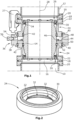
- Fig. 1
- eine schematische Schnittansicht einer bevorzugten Ausführungsform einer erfindungsgemäßen Verbindungseinrichtung,
- Fig. 2
- eine schematische Schnittansicht eines Verbindungselements und
- Fig. 3
- eine schematische Schnittansicht einer zweiten Ausführungsform einer erfindungsgemäßen Verbindungseinrichtung.
- Die Verbindungseinrichtung dient zum Verbinden eines ersten Rohrendes 10, das insbesondere mit einer Vakuumpumpe verbunden ist mit einem zweiten Rohrende 12, das insbesondere mit einer zu evakuierenden Kammer verbunden ist. Zur fluidischen Verbindung ist ein Rohrelement 14 vorgesehen. Dieses ist an seinen beiden gegenüberliegenden Enden insbesondere über nicht dargestellte Befestigungsschrauben jeweils mit einem Verbindungsring 16 verbunden. Der Ring 16 weist einen Zentrierring 18 mit Dichtung auf. Der Zentrierring 18 ist jeweils zwischen Flanschen 20 der beiden Rohrenden 10, 12 und diesen gegenüberliegenden Flanschen 22 angeordnet. Die Flansche 22 sind jeweils Teile von zwei Halteelementen 24. Die Halteelemente 24 sind jeweils ringförmig ausgebildet und umgeben das Rohrelement 14. Die beiden Halteelemente 24 sind beispielsweise über Klammern 27 jeweils mit dem ersten Rohrende 10 bzw. mit dem zweiten Rohrende 12 fest und somit starr verbunden.
- Das Rohrelement 14 ist über Verbindungselemente 26 mit den beiden Rohrelementen 10, 12 verbunden, wobei auch die beiden Halteelemente 24 Bestandteile der Verbindungselemente 26 sind. Die Verbindung erfolgt hierbei derart, dass durch die Verbindung insbesondere bei einem Ausfall der Vakuumpumpe Momente übertragen werden können. Hierbei handelt es sich um die auftretenden Momente um eine Längsachse 28. In axialer Richtung, d.h. in Richtung einer Längsachse 28 ist ein zumindest geringfügiges Verschieben des Rohrelements relativ zu den beiden Rohrenden 10, 12 bzw. relativ zu den beiden mit den Rohrenden 10, 12 fest verbundenen Halteelementen 24 möglich. Hierzu weisen die Halteelemente 24 (
Fig. 2 ) einen radial nach innen weisenden Ansatz 30 auf. Der Ansatz 30 weist Ausnehmungen 32 auf, in die Ansätze 34 (Fig. 1 ) ragen. Im dargestellten Aufführungsbeispiel handelt es sich bei den Ansätzen 34 um Schraubenköpfe. Hierzu ist der Durchmesser der Ausnehmungen 32 etwas größer als der Durchmesser der Schraubenköpfe 34. - Des Weiteren weist die Verbindungseinrichtung ein Entkopplungselement 36 auf. Dies dient zur mechanischen Entkopplung der beiden Verbindungselemente 26 von den beiden Rohrenden 10,12, so dass keine Axialkräfte, d.h. Kräfte, die in Richtung der Längsachse 28 verlaufen übertragen werden können bzw. deren Übertragung stark gedämpft ist. Insofern erfolgt keine bzw. eine sehr geringe Übertragung von Schwingungen von der Vakuumpumpe auf die zu evakuierende Kammer und die mit dieser verbundenen Bauteile. Das Entkopplungselement 36 weist in dem dargestellten Ausführungsbeispiel ein ringförmig ausgebildetes Außenelement 38 auf. Das Außenelement 38 ist gegenüber den ebenfalls ringförmig ausgebildeten beiden Halteelementen 24 in axialer Richtung, d.h. in Längsrichtung 28 verschiebbar. Zwischen dem Außenelement 38 und den beiden Halteelementen 24 ist jeweils ein ringförmiges Dichtelement 40 angeordnet.
- Auf einer Innenseite der beiden Halteelemente 24 ist gegebenenfalls ein ringförmiges Dichtelement 42 zur Abdichtung gegenüber dem Rohrelement 14 vorgesehen. Insbesondere ist auch in diesem Bereich eine axiale Bewegbarkeit zwischen den Halteelementen 24 und dem Rohrelement 14 gegeben.
- Das Außenelement 38 des Entkopplungselements 36 ist über ein Stegelement 44 mit dem Rohrelement 14 verbunden. Hierbei handelt es sich um eine feste Verbindung, wobei das Stegelement 44 mit einem stegförmigen Ansatz 46 des Rohrelements 14 beispielsweise durch Verschrauben verbunden ist. Eine axiale Bewegung des Rohrelements 14 bewirkt somit stets auch eine axiale Bewegung des Außenelements 38.
- Zur Realisierung von Axialbewegungen sind zwei Fluidkammern 48, 50 ausgebildet, die in dem in
Fig. 1 dargestellten Ausführungsbeispiel über einen in den Stegen 44, 46 vorgesehenen Verbindungskanal 52 fluidisch miteinander verbunden sind. Die Fluidkammern 48, 50 sind somit durch eine Innenseite des Außenelements 38, Stirnseiten der beiden Halteelemente 24 und ein Außenseite des Rohrelements 14 begrenzt. Die Fluidkammern 48, 50 weisen einen Zuführkanal 54 auf, in dem ein Ventil 56 angeordnet ist. Über das Ventil 56 kann somit den beiden Fluidkammern 48, 50 ein Fluid, insbesondere Druckluft zu- oder abgeführt werden. - Zur axialen Entkopplung der beiden Rohrenden 10, 12 und somit zur Vermeidung und insbesondere Verringerung der Übertragung von Schwingungen ist es mit Hilfe der erfindungsgemäßen Verbindungseinrichtung möglich in den Fluidkammern 48, 50 Druck aufzubauen. Dies führt zu einem Auseinanderdrücken der beiden einander gegenüber liegenden ringförmigen Halteelemente 24. Vor Inbetriebnahme der Vakuumpumpe führt dies zu einer axialen Verbindung zwischen den beiden Rohrenden 10, 12, da die Ansätze bzw. Schraubenköpfe 34 axial jeweils am Boden der Ausnehmungen 32 anliegen. Im Betrieb wird durch die Vakuumpumpe in dem Rohrelement 14 und zusätzlich auch in den beiden Rohrenden 10, 12 ein Vakuum erzeugt. Hierdurch entsteht eine Gegenkraft. Diese bewirkt bei einem entsprechenden Kräfteverhältnis, dass die Ansätze 34 nicht mehr am Bodenbereich der Ausnehmungen 32 anliegen.
- Um eine sichere Entkopplung zu gewährleisten, muss somit der Druck in den Fluidkammern 48, 50 auf das Vakuum angepasst werden. Dies ist erfindungsgemäß auf einfache Weise durch Zu- oder Abführen von Druckluft durch den Zuführkanal 54 möglich.
- Des Weiteren ist es bevorzugt, dass an dem Außenring 38 und/oder einem der beiden Halteelemente 24 eine Markierung vorgesehen ist, so dass die Lage des Außenrings 38 und somit auch des Rohrelements 14 relativ zu den Halteelementen 24 auf einfache Weise ablesbar ist. Hierdurch kann auf einfache Weise der erforderliche Druck in den Fluidkammern 48, 50 ermittelt werden, um eine axiale Entkopplung zu gewährleisten.
- Bei der in
Fig. 3 dargestellten Ausführungsform sind ähnliche und identische Bauteile mit denselben Bezugszeichen gekennzeichnet. - Der wesentliche Unterschied besteht darin, dass der Außenring 38 mit dem Rohrelement 14 einstückig ausgebildet ist. Die Verbindung erfolgt im dargestellten Ausführungsbeispiel über einen massiv ausgebildeten Steg 58. Der Steg 58 weist im dargestellten Ausführungsbeispiel auch keine Bohrungen zur Verbindung der beiden Fluidkammern 48, 50 auf. Vielmehr ist je Fluidkammer 48, 50 jeweils ein Zuführkanal 60 vorgesehen, in dem jeweils ein Ventil 62 angeordnet ist. Hierdurch ist es möglich den Druck in den beiden Fluidkammern 48, 50 unabhängig voneinander einzustellen, so dass eine Feinjustage möglich ist. Insofern ist es auch bei dieser Ausführungsform bevorzugt, dass zwei Markierungen vorgesehen sind, wobei eine Markierung die relative Lage zwischen dem Außenelement 38 und einem in
Fig. 1 oberen Halteelement 24 und die zweite Markierung die relative Lage zu dem inFig. 3 unteren Halteelement 24 veranschaulicht.
Claims (16)
- Verbindungseinrichtung zum Verbinden eines mit einer Vakuumpumpe verbindbaren ersten Rohrendes (10) mit einem mit einer zu evakuierenden Kammer verbindbaren zweiten Rohrende (12), miteinem Rohrelement (14) zur fluidischen Verbindung der Vakuumpumpe mit der zu evakuierenden Kammer,wobei das Rohrelement (14) an jeder Seite ein Verbindungselement (26) zum Verbinden mit jeweils einem der Rohrenden (10, 12) aufweist,wobei zumindest eines der beiden Verbindungselemente (26) im Betrieb ausschließlich zur Übertragung von Momenten geeignet ist undeinem Entkopplungselement (36) zur mechanischen axialen Entkopplung des zumindest einen ausschließlich zur Übertragung von Momenten geeigneten Verbindungselements (26) von dem entsprechenden Rohrende (10), (12)dadurch gekennzeichnet, dassdas Entkopplungselement (36) zumindest eine mit komprimierbarem Fluid insbesondere Gas gefüllte Fluidkammer (48, 50) aufweist.
- Verbindungseinrichtung nach Anspruch 1, dadurch gekennzeichnet, dass die von dem Entkopplungselement (36) erzeugte Kraft insbesondere die erzeugte Axialkraft einstellbar ist.
- Verbindungseinrichtung nach Anspruch 2, dadurch gekennzeichnet, dass die Einstellung der Axialkraft durch Druckänderung in der Fluidkammer (48, 50) erfolgt.
- Verbindungseinrichtung nach einem der Ansprüche 1 bis 3, dadurch gekennzeichnet, dass beide Verbindungselemente (26) ausschließlich zur Übertragung von Momenten geeignet sind.
- Verbindungseinrichtung nach einem der Ansprüche 1 bis 4, dadurch gekennzeichnet, dass das Entkopplungselement (36) zwei Halteelemente (24) aufweist, die fest mit jeweils einem der Rohrenden (10, 12) verbindbar sind, wobei die Fluidkammer (48, 50) vorzugsweise zwischen den beiden Halteelementen (24) angeordnet ist.
- Verbindungseinrichtung nach einem der Ansprüche 1 bis 5, dadurch gekennzeichnet, dass das Entkopplungselement (36) ein das Rohrelement (14) insbesondere vollständig umgebendes Außenelement (38) aufweist.
- Verbindungseinrichtung nach Anspruch 6, dadurch gekennzeichnet, dass das Außenelement (38) relativ zu zumindest einem insbesondere beiden Halteelementen (24) axial verschiebbar ist.
- Verbindungseinrichtung nach einem der Ansprüche 6 oder 7, gekennzeichnet durch ein zwischen dem Außenelement (38) und dem relativ zu diesem verschiebbaren Halteelement (24) angeordneten ersten Dichtelement (40) und vorzugsweise durch ein zweites Dichtelement (40), dass zwischen dem Außenelement (38) und dem zweiten insbesondere ebenfalls axial verschiebbaren Halteelement (24) angeordnet ist.
- Verbindungseinrichtung nach einem der Ansprüche 5 bis 8, dadurch gekennzeichnet, dass zwischen dem Rohrelement (14) und den beiden Halteelementen (24) jeweils ein Dichtelement (42) angeordnet ist.
- Verbindungseinrichtung nach einem der Ansprüche 6 bis 9, dadurch gekennzeichnet, dass die mindestens eine Fluidkammer (48, 50) von dem Außenelement (38), dem Rohrelement (14) und den beiden Halteelementen (24) begrenzt ist.
- Verbindungseinrichtung nach einem der Ansprüche 1 bis 10, dadurch gekennzeichnet, dass die mindestens eine Fluidkammer (48, 50) das Rohrelement (14) ringförmig umgibt.
- Verbindungseinrichtung nach einem der Ansprüche 1 bis 11, dadurch gekennzeichnet, dass die mindestens eine Fluidkammer (48, 50) einen Zuführkanal (54, 60) aufweist, in dem insbesondere ein Ventil (56, 62) angeordnet ist.
- Verbindungseinrichtung nach einem der Ansprüche 6 bis 12, dadurch gekennzeichnet, dass das Außenelement (38) mit dem Rohrelement (14), insbesondere über ein Stegelement (44, 58) fest verbunden, insbesondere einstückig ausgebildet ist.
- Verbindungseinrichtung nach einem der Ansprüche 1 bis 13, dadurch gekennzeichnet, dass das Entkoppelelement (36) zwei Fluidkammern (48, 50) aufweist, deren Druck vorzugsweise getrennt voneinander einstellbar ist.
- Verbindungseinrichtung nach einem der Ansprüche 1 bis 14, dadurch gekennzeichnet, dass das zumindest eine ausschließlich zur Übertragung von Momenten geeignete Verbindungselement (26) insbesondere axial angeordnete Ansätze (34) aufweist, die in Ausnehmungen (32) ragen wobei vorzugsweise der Querschnitt der Ausnehmungen (32) größer als der Querschnitt der Ansätze (34) ist, so dass im Normalbetrieb keine Momente übertragen werden.
- Verbindungseinrichtung nach einem der Ansprüche 6 bis 15, dadurch gekennzeichnet, dass das Außenelement und/oder zumindest eines der Halteelemente (24) eine Markierung aufweist, um im Betrieb die mechanische Entkopplung anzuzeigen.
Applications Claiming Priority (2)
| Application Number | Priority Date | Filing Date | Title |
|---|---|---|---|
| DE202015008803.1U DE202015008803U1 (de) | 2015-12-23 | 2015-12-23 | Verbindungseinrichtung |
| PCT/EP2016/080975 WO2017108528A1 (de) | 2015-12-23 | 2016-12-14 | Verbindungseinrichtung |
Publications (2)
| Publication Number | Publication Date |
|---|---|
| EP3394452A1 EP3394452A1 (de) | 2018-10-31 |
| EP3394452B1 true EP3394452B1 (de) | 2023-09-27 |
Family
ID=57777579
Family Applications (1)
| Application Number | Title | Priority Date | Filing Date |
|---|---|---|---|
| EP16825345.8A Active EP3394452B1 (de) | 2015-12-23 | 2016-12-14 | Verbindungseinrichtung |
Country Status (8)
| Country | Link |
|---|---|
| US (1) | US11143351B2 (de) |
| EP (1) | EP3394452B1 (de) |
| JP (1) | JP6937306B2 (de) |
| KR (1) | KR20180098262A (de) |
| CN (1) | CN108474382B (de) |
| DE (1) | DE202015008803U1 (de) |
| SG (1) | SG11201805307TA (de) |
| WO (1) | WO2017108528A1 (de) |
Families Citing this family (2)
| Publication number | Priority date | Publication date | Assignee | Title |
|---|---|---|---|---|
| GB2587367A (en) | 2019-09-24 | 2021-03-31 | Edwards Ltd | Vibration damping connector systems |
| GB2641282A (en) * | 2024-05-24 | 2025-11-26 | Edwards Ltd | Differentially pumped vibration isolator |
Citations (2)
| Publication number | Priority date | Publication date | Assignee | Title |
|---|---|---|---|---|
| US4523612A (en) * | 1983-04-15 | 1985-06-18 | The United States Of America As Represented By The United States Department Of Energy | Apparatus and method for suppressing vibration and displacement of a bellows |
| WO2015055985A1 (en) * | 2013-10-14 | 2015-04-23 | Edwards Limited | Vacuum system pipe couplings |
Family Cites Families (24)
| Publication number | Priority date | Publication date | Assignee | Title |
|---|---|---|---|---|
| US1499050A (en) | 1921-06-17 | 1924-06-24 | Ernest L Broome | Flexible expansion joint |
| US3298980A (en) | 1963-08-01 | 1967-01-17 | Union Carbide Corp | Alkylene oxide polymer compositions flexibilized with salts of carboxylic acids |
| US3298680A (en) * | 1964-06-02 | 1967-01-17 | Bethlehem Steel Corp | Vacuum degassing apparatus |
| US5671956A (en) * | 1996-03-07 | 1997-09-30 | Kimball Physics, Inc. | Vacuum system coupler |
| DE10119075A1 (de) | 2001-04-19 | 2002-10-24 | Leybold Vakuum Gmbh | Vakuumleitung |
| JP4250353B2 (ja) | 2001-06-22 | 2009-04-08 | エドワーズ株式会社 | 真空ポンプ |
| GB0402625D0 (en) | 2004-02-06 | 2004-03-10 | Boc Group Plc | Vibration damper |
| FR2867823B1 (fr) * | 2004-03-22 | 2006-07-14 | Cit Alcatel | Raccord amortisseur pour pompe a vide |
| JP2006077714A (ja) * | 2004-09-10 | 2006-03-23 | Boc Edwards Kk | ダンパ及び真空ポンプ |
| DE202005011679U1 (de) * | 2004-09-16 | 2005-10-20 | Leybold Vacuum Gmbh | Vakuumpumpen-Schwingungsdämpfer |
| DE102005020904A1 (de) * | 2005-05-07 | 2006-11-09 | Leybold Vacuum Gmbh | Vakuum-Pumpenanordnung |
| DE102006004314A1 (de) * | 2006-01-31 | 2007-08-02 | Leybold Vacuum Gmbh | Vakuumleitung |
| GB0620723D0 (en) | 2006-10-19 | 2006-11-29 | Boc Group Plc | Vibration isolator |
| DE102007008859A1 (de) * | 2007-02-23 | 2008-08-28 | Oerlikon Leybold Vacuum Gmbh | Vakuumleitung |
| JP2009097673A (ja) * | 2007-10-18 | 2009-05-07 | Kurashiki Kako Co Ltd | 防振継手 |
| DE102008027006A1 (de) * | 2007-12-03 | 2009-06-04 | Sms Mevac Gmbh | Vorrichtung zur sekundär- und vakuum-metallurgischen Behandlung von flüssigem Stahl |
| DE102007061188A1 (de) * | 2007-12-17 | 2009-06-18 | Vat Holding Ag | Flanscheinrichtung |
| DE102008028199A1 (de) * | 2008-06-12 | 2009-12-17 | Pfeiffer Vacuum Gmbh | Verbindungselement |
| JP5480545B2 (ja) * | 2009-07-03 | 2014-04-23 | 倉敷化工株式会社 | 防振継手 |
| CN201507593U (zh) * | 2009-08-25 | 2010-06-16 | 东莞宏威数码机械有限公司 | 减震装置 |
| IT1399567B1 (it) | 2010-04-16 | 2013-04-19 | Varian Spa | Smorzatore di vibrazioni per pompe di vuoto |
| JP5632992B2 (ja) * | 2010-11-22 | 2014-12-03 | 日本電子株式会社 | ターボ分子ポンプの接続装置 |
| US9249911B2 (en) * | 2011-07-06 | 2016-02-02 | The Victaulic Co., Of Japan, Ltd. | Flexible expansion joint |
| DE102013100483A1 (de) * | 2013-01-17 | 2014-07-17 | Andreas von Keitz | Nottrennkupplung |
-
2015
- 2015-12-23 DE DE202015008803.1U patent/DE202015008803U1/de not_active Expired - Lifetime
-
2016
- 2016-12-14 EP EP16825345.8A patent/EP3394452B1/de active Active
- 2016-12-14 US US16/060,288 patent/US11143351B2/en not_active Expired - Fee Related
- 2016-12-14 WO PCT/EP2016/080975 patent/WO2017108528A1/de not_active Ceased
- 2016-12-14 SG SG11201805307TA patent/SG11201805307TA/en unknown
- 2016-12-14 KR KR1020187017742A patent/KR20180098262A/ko not_active Abandoned
- 2016-12-14 CN CN201680075873.6A patent/CN108474382B/zh active Active
- 2016-12-14 JP JP2018532390A patent/JP6937306B2/ja active Active
Patent Citations (2)
| Publication number | Priority date | Publication date | Assignee | Title |
|---|---|---|---|---|
| US4523612A (en) * | 1983-04-15 | 1985-06-18 | The United States Of America As Represented By The United States Department Of Energy | Apparatus and method for suppressing vibration and displacement of a bellows |
| WO2015055985A1 (en) * | 2013-10-14 | 2015-04-23 | Edwards Limited | Vacuum system pipe couplings |
Also Published As
| Publication number | Publication date |
|---|---|
| CN108474382A (zh) | 2018-08-31 |
| JP2019501351A (ja) | 2019-01-17 |
| WO2017108528A1 (de) | 2017-06-29 |
| US11143351B2 (en) | 2021-10-12 |
| DE202015008803U1 (de) | 2017-03-24 |
| CN108474382B (zh) | 2021-01-22 |
| KR20180098262A (ko) | 2018-09-03 |
| JP6937306B2 (ja) | 2021-09-22 |
| EP3394452A1 (de) | 2018-10-31 |
| US20180363825A1 (en) | 2018-12-20 |
| SG11201805307TA (en) | 2018-07-30 |
Similar Documents
| Publication | Publication Date | Title |
|---|---|---|
| EP2019219B1 (de) | Verbindung zweier um eine gemeinsame Rotationsachse drehbare Körper | |
| EP3377796B1 (de) | Kupplungselement für eine kupplung zur verbindung von druckmittelleitungen | |
| DE102015208787B4 (de) | Verstellbarer Federträger | |
| EP3394452B1 (de) | Verbindungseinrichtung | |
| EP2126444B1 (de) | Vakuumleitung | |
| AT519493A2 (de) | Dehnspannhülse, Werkzeughalter mit einer solchen Dehnspannhülse sowie Verfahren zum Spannen eines Werkzeugs | |
| EP2994659B1 (de) | Anordnung mit hohlwelle, antriebswelle und spannvorrichtung | |
| DE102009022206B3 (de) | Lagerung mit einer Brems- und/oder Klemmvorrichtung | |
| EP3271623B1 (de) | Hubventil mit drehentkopplungseinrichtung | |
| DE102012008797B3 (de) | Klemmvorrichtung | |
| EP3683481B1 (de) | Pass- und ausbaustück für rohrleitungen | |
| EP2776733B1 (de) | Druckmittelbetätigte bremse | |
| DE102017115207A1 (de) | Alternative Tellerfedermontage für Kupplungsausrücklager mit Selbstzentrierungsfunktion | |
| WO2017054927A2 (de) | Verspanneinheit für wälzlager auf achsen und wellen | |
| WO2016192726A1 (de) | Einrichtung zur übertragung von drehmoment | |
| DE102014223545A1 (de) | Rampensystem für eine Nachstelleinrichtung | |
| EP3049296B1 (de) | Bremskraftverstärker für eine kraftfahrzeugbremsanlage mit rückhalteeinrichtung für rückstellfeder und bremskraftverstärkungsanordnung | |
| AT528403B1 (de) | Kupplungsvorrichtung zur drehmomentübertragenden Verbindung zweier Wellen | |
| DE102017213310A1 (de) | Vorrichtung zur Vermeidung von Verschleiß der axialen Flächen eines Abtriebswellenlagers und eines mit einer Abtriebswelle verbundenen Abtriebsflansches eines Getriebes eines Kraftfahrzeugs aufgrund von Reibung | |
| DE102015212532A1 (de) | Montagewerkzeug, Montageverfahren sowie Verwendung eines flexiblen Bandes | |
| EP4402396B1 (de) | Gleitringdichtungsanordnung mit verbesserter axialkraftabstützung | |
| EP2442000A1 (de) | Verbindungsvorrichtung für zwei sich abschnittsweise überlappende Leitungen | |
| DE202023102225U1 (de) | Stellgerät | |
| DE102018125240A1 (de) | Bajonettanbindung eines Ausrücklagers | |
| DE10314619A1 (de) | Rohrverbindung |
Legal Events
| Date | Code | Title | Description |
|---|---|---|---|
| STAA | Information on the status of an ep patent application or granted ep patent |
Free format text: STATUS: UNKNOWN |
|
| STAA | Information on the status of an ep patent application or granted ep patent |
Free format text: STATUS: THE INTERNATIONAL PUBLICATION HAS BEEN MADE |
|
| PUAI | Public reference made under article 153(3) epc to a published international application that has entered the european phase |
Free format text: ORIGINAL CODE: 0009012 |
|
| STAA | Information on the status of an ep patent application or granted ep patent |
Free format text: STATUS: REQUEST FOR EXAMINATION WAS MADE |
|
| 17P | Request for examination filed |
Effective date: 20180716 |
|
| AK | Designated contracting states |
Kind code of ref document: A1 Designated state(s): AL AT BE BG CH CY CZ DE DK EE ES FI FR GB GR HR HU IE IS IT LI LT LU LV MC MK MT NL NO PL PT RO RS SE SI SK SM TR |
|
| AX | Request for extension of the european patent |
Extension state: BA ME |
|
| DAV | Request for validation of the european patent (deleted) | ||
| DAX | Request for extension of the european patent (deleted) | ||
| STAA | Information on the status of an ep patent application or granted ep patent |
Free format text: STATUS: EXAMINATION IS IN PROGRESS |
|
| 17Q | First examination report despatched |
Effective date: 20200514 |
|
| GRAP | Despatch of communication of intention to grant a patent |
Free format text: ORIGINAL CODE: EPIDOSNIGR1 |
|
| STAA | Information on the status of an ep patent application or granted ep patent |
Free format text: STATUS: GRANT OF PATENT IS INTENDED |
|
| INTG | Intention to grant announced |
Effective date: 20230711 |
|
| GRAS | Grant fee paid |
Free format text: ORIGINAL CODE: EPIDOSNIGR3 |
|
| GRAA | (expected) grant |
Free format text: ORIGINAL CODE: 0009210 |
|
| STAA | Information on the status of an ep patent application or granted ep patent |
Free format text: STATUS: THE PATENT HAS BEEN GRANTED |
|
| AK | Designated contracting states |
Kind code of ref document: B1 Designated state(s): AL AT BE BG CH CY CZ DE DK EE ES FI FR GB GR HR HU IE IS IT LI LT LU LV MC MK MT NL NO PL PT RO RS SE SI SK SM TR |
|
| REG | Reference to a national code |
Ref country code: GB Ref legal event code: FG4D Free format text: NOT ENGLISH |
|
| REG | Reference to a national code |
Ref country code: CH Ref legal event code: EP |
|
| P01 | Opt-out of the competence of the unified patent court (upc) registered |
Effective date: 20230830 |
|
| REG | Reference to a national code |
Ref country code: DE Ref legal event code: R096 Ref document number: 502016016120 Country of ref document: DE |
|
| REG | Reference to a national code |
Ref country code: IE Ref legal event code: FG4D Free format text: LANGUAGE OF EP DOCUMENT: GERMAN |
|
| REG | Reference to a national code |
Ref country code: LT Ref legal event code: MG9D |
|
| PG25 | Lapsed in a contracting state [announced via postgrant information from national office to epo] |
Ref country code: GR Free format text: LAPSE BECAUSE OF FAILURE TO SUBMIT A TRANSLATION OF THE DESCRIPTION OR TO PAY THE FEE WITHIN THE PRESCRIBED TIME-LIMIT Effective date: 20231228 |
|
| PG25 | Lapsed in a contracting state [announced via postgrant information from national office to epo] |
Ref country code: SE Free format text: LAPSE BECAUSE OF FAILURE TO SUBMIT A TRANSLATION OF THE DESCRIPTION OR TO PAY THE FEE WITHIN THE PRESCRIBED TIME-LIMIT Effective date: 20230927 Ref country code: RS Free format text: LAPSE BECAUSE OF FAILURE TO SUBMIT A TRANSLATION OF THE DESCRIPTION OR TO PAY THE FEE WITHIN THE PRESCRIBED TIME-LIMIT Effective date: 20230927 Ref country code: NO Free format text: LAPSE BECAUSE OF FAILURE TO SUBMIT A TRANSLATION OF THE DESCRIPTION OR TO PAY THE FEE WITHIN THE PRESCRIBED TIME-LIMIT Effective date: 20231227 Ref country code: LV Free format text: LAPSE BECAUSE OF FAILURE TO SUBMIT A TRANSLATION OF THE DESCRIPTION OR TO PAY THE FEE WITHIN THE PRESCRIBED TIME-LIMIT Effective date: 20230927 Ref country code: LT Free format text: LAPSE BECAUSE OF FAILURE TO SUBMIT A TRANSLATION OF THE DESCRIPTION OR TO PAY THE FEE WITHIN THE PRESCRIBED TIME-LIMIT Effective date: 20230927 Ref country code: HR Free format text: LAPSE BECAUSE OF FAILURE TO SUBMIT A TRANSLATION OF THE DESCRIPTION OR TO PAY THE FEE WITHIN THE PRESCRIBED TIME-LIMIT Effective date: 20230927 Ref country code: GR Free format text: LAPSE BECAUSE OF FAILURE TO SUBMIT A TRANSLATION OF THE DESCRIPTION OR TO PAY THE FEE WITHIN THE PRESCRIBED TIME-LIMIT Effective date: 20231228 Ref country code: FI Free format text: LAPSE BECAUSE OF FAILURE TO SUBMIT A TRANSLATION OF THE DESCRIPTION OR TO PAY THE FEE WITHIN THE PRESCRIBED TIME-LIMIT Effective date: 20230927 |
|
| REG | Reference to a national code |
Ref country code: NL Ref legal event code: MP Effective date: 20230927 |
|
| PG25 | Lapsed in a contracting state [announced via postgrant information from national office to epo] |
Ref country code: NL Free format text: LAPSE BECAUSE OF FAILURE TO SUBMIT A TRANSLATION OF THE DESCRIPTION OR TO PAY THE FEE WITHIN THE PRESCRIBED TIME-LIMIT Effective date: 20230927 |
|
| PG25 | Lapsed in a contracting state [announced via postgrant information from national office to epo] |
Ref country code: IS Free format text: LAPSE BECAUSE OF FAILURE TO SUBMIT A TRANSLATION OF THE DESCRIPTION OR TO PAY THE FEE WITHIN THE PRESCRIBED TIME-LIMIT Effective date: 20240127 |
|
| PG25 | Lapsed in a contracting state [announced via postgrant information from national office to epo] |
Ref country code: ES Free format text: LAPSE BECAUSE OF FAILURE TO SUBMIT A TRANSLATION OF THE DESCRIPTION OR TO PAY THE FEE WITHIN THE PRESCRIBED TIME-LIMIT Effective date: 20230927 |
|
| PG25 | Lapsed in a contracting state [announced via postgrant information from national office to epo] |
Ref country code: SM Free format text: LAPSE BECAUSE OF FAILURE TO SUBMIT A TRANSLATION OF THE DESCRIPTION OR TO PAY THE FEE WITHIN THE PRESCRIBED TIME-LIMIT Effective date: 20230927 Ref country code: RO Free format text: LAPSE BECAUSE OF FAILURE TO SUBMIT A TRANSLATION OF THE DESCRIPTION OR TO PAY THE FEE WITHIN THE PRESCRIBED TIME-LIMIT Effective date: 20230927 Ref country code: IS Free format text: LAPSE BECAUSE OF FAILURE TO SUBMIT A TRANSLATION OF THE DESCRIPTION OR TO PAY THE FEE WITHIN THE PRESCRIBED TIME-LIMIT Effective date: 20240127 Ref country code: ES Free format text: LAPSE BECAUSE OF FAILURE TO SUBMIT A TRANSLATION OF THE DESCRIPTION OR TO PAY THE FEE WITHIN THE PRESCRIBED TIME-LIMIT Effective date: 20230927 Ref country code: EE Free format text: LAPSE BECAUSE OF FAILURE TO SUBMIT A TRANSLATION OF THE DESCRIPTION OR TO PAY THE FEE WITHIN THE PRESCRIBED TIME-LIMIT Effective date: 20230927 Ref country code: SK Free format text: LAPSE BECAUSE OF FAILURE TO SUBMIT A TRANSLATION OF THE DESCRIPTION OR TO PAY THE FEE WITHIN THE PRESCRIBED TIME-LIMIT Effective date: 20230927 Ref country code: PT Free format text: LAPSE BECAUSE OF FAILURE TO SUBMIT A TRANSLATION OF THE DESCRIPTION OR TO PAY THE FEE WITHIN THE PRESCRIBED TIME-LIMIT Effective date: 20240129 |
|
| PG25 | Lapsed in a contracting state [announced via postgrant information from national office to epo] |
Ref country code: PL Free format text: LAPSE BECAUSE OF FAILURE TO SUBMIT A TRANSLATION OF THE DESCRIPTION OR TO PAY THE FEE WITHIN THE PRESCRIBED TIME-LIMIT Effective date: 20230927 |
|
| REG | Reference to a national code |
Ref country code: DE Ref legal event code: R097 Ref document number: 502016016120 Country of ref document: DE |
|
| PG25 | Lapsed in a contracting state [announced via postgrant information from national office to epo] |
Ref country code: DK Free format text: LAPSE BECAUSE OF FAILURE TO SUBMIT A TRANSLATION OF THE DESCRIPTION OR TO PAY THE FEE WITHIN THE PRESCRIBED TIME-LIMIT Effective date: 20230927 |
|
| PG25 | Lapsed in a contracting state [announced via postgrant information from national office to epo] |
Ref country code: DK Free format text: LAPSE BECAUSE OF FAILURE TO SUBMIT A TRANSLATION OF THE DESCRIPTION OR TO PAY THE FEE WITHIN THE PRESCRIBED TIME-LIMIT Effective date: 20230927 |
|
| REG | Reference to a national code |
Ref country code: CH Ref legal event code: PL |
|
| PLBE | No opposition filed within time limit |
Free format text: ORIGINAL CODE: 0009261 |
|
| STAA | Information on the status of an ep patent application or granted ep patent |
Free format text: STATUS: NO OPPOSITION FILED WITHIN TIME LIMIT |
|
| PG25 | Lapsed in a contracting state [announced via postgrant information from national office to epo] |
Ref country code: LU Free format text: LAPSE BECAUSE OF NON-PAYMENT OF DUE FEES Effective date: 20231214 |
|
| PG25 | Lapsed in a contracting state [announced via postgrant information from national office to epo] |
Ref country code: MC Free format text: LAPSE BECAUSE OF FAILURE TO SUBMIT A TRANSLATION OF THE DESCRIPTION OR TO PAY THE FEE WITHIN THE PRESCRIBED TIME-LIMIT Effective date: 20230927 |
|
| REG | Reference to a national code |
Ref country code: BE Ref legal event code: MM Effective date: 20231231 |
|
| PG25 | Lapsed in a contracting state [announced via postgrant information from national office to epo] |
Ref country code: MC Free format text: LAPSE BECAUSE OF FAILURE TO SUBMIT A TRANSLATION OF THE DESCRIPTION OR TO PAY THE FEE WITHIN THE PRESCRIBED TIME-LIMIT Effective date: 20230927 Ref country code: LU Free format text: LAPSE BECAUSE OF NON-PAYMENT OF DUE FEES Effective date: 20231214 |
|
| 26N | No opposition filed |
Effective date: 20240628 |
|
| REG | Reference to a national code |
Ref country code: IE Ref legal event code: MM4A |
|
| PG25 | Lapsed in a contracting state [announced via postgrant information from national office to epo] |
Ref country code: IE Free format text: LAPSE BECAUSE OF NON-PAYMENT OF DUE FEES Effective date: 20231214 |
|
| PG25 | Lapsed in a contracting state [announced via postgrant information from national office to epo] |
Ref country code: BE Free format text: LAPSE BECAUSE OF NON-PAYMENT OF DUE FEES Effective date: 20231231 |
|
| PG25 | Lapsed in a contracting state [announced via postgrant information from national office to epo] |
Ref country code: CH Free format text: LAPSE BECAUSE OF NON-PAYMENT OF DUE FEES Effective date: 20231231 |
|
| PG25 | Lapsed in a contracting state [announced via postgrant information from national office to epo] |
Ref country code: SI Free format text: LAPSE BECAUSE OF FAILURE TO SUBMIT A TRANSLATION OF THE DESCRIPTION OR TO PAY THE FEE WITHIN THE PRESCRIBED TIME-LIMIT Effective date: 20230927 |
|
| PG25 | Lapsed in a contracting state [announced via postgrant information from national office to epo] |
Ref country code: SI Free format text: LAPSE BECAUSE OF FAILURE TO SUBMIT A TRANSLATION OF THE DESCRIPTION OR TO PAY THE FEE WITHIN THE PRESCRIBED TIME-LIMIT Effective date: 20230927 Ref country code: IE Free format text: LAPSE BECAUSE OF NON-PAYMENT OF DUE FEES Effective date: 20231214 Ref country code: CH Free format text: LAPSE BECAUSE OF NON-PAYMENT OF DUE FEES Effective date: 20231231 Ref country code: BE Free format text: LAPSE BECAUSE OF NON-PAYMENT OF DUE FEES Effective date: 20231231 |
|
| PG25 | Lapsed in a contracting state [announced via postgrant information from national office to epo] |
Ref country code: BG Free format text: LAPSE BECAUSE OF FAILURE TO SUBMIT A TRANSLATION OF THE DESCRIPTION OR TO PAY THE FEE WITHIN THE PRESCRIBED TIME-LIMIT Effective date: 20230927 |
|
| PG25 | Lapsed in a contracting state [announced via postgrant information from national office to epo] |
Ref country code: BG Free format text: LAPSE BECAUSE OF FAILURE TO SUBMIT A TRANSLATION OF THE DESCRIPTION OR TO PAY THE FEE WITHIN THE PRESCRIBED TIME-LIMIT Effective date: 20230927 |
|
| PGFP | Annual fee paid to national office [announced via postgrant information from national office to epo] |
Ref country code: GB Payment date: 20241227 Year of fee payment: 9 |
|
| PGFP | Annual fee paid to national office [announced via postgrant information from national office to epo] |
Ref country code: FR Payment date: 20241226 Year of fee payment: 9 |
|
| PGFP | Annual fee paid to national office [announced via postgrant information from national office to epo] |
Ref country code: CZ Payment date: 20241122 Year of fee payment: 9 |
|
| PGFP | Annual fee paid to national office [announced via postgrant information from national office to epo] |
Ref country code: IT Payment date: 20241218 Year of fee payment: 9 |
|
| REG | Reference to a national code |
Ref country code: AT Ref legal event code: MM01 Ref document number: 1615671 Country of ref document: AT Kind code of ref document: T Effective date: 20231214 |
|
| PGFP | Annual fee paid to national office [announced via postgrant information from national office to epo] |
Ref country code: DE Payment date: 20241227 Year of fee payment: 9 |
|
| PG25 | Lapsed in a contracting state [announced via postgrant information from national office to epo] |
Ref country code: AT Free format text: LAPSE BECAUSE OF NON-PAYMENT OF DUE FEES Effective date: 20231214 |
|
| PG25 | Lapsed in a contracting state [announced via postgrant information from national office to epo] |
Ref country code: CY Free format text: LAPSE BECAUSE OF FAILURE TO SUBMIT A TRANSLATION OF THE DESCRIPTION OR TO PAY THE FEE WITHIN THE PRESCRIBED TIME-LIMIT; INVALID AB INITIO Effective date: 20161214 |
|
| PG25 | Lapsed in a contracting state [announced via postgrant information from national office to epo] |
Ref country code: HU Free format text: LAPSE BECAUSE OF FAILURE TO SUBMIT A TRANSLATION OF THE DESCRIPTION OR TO PAY THE FEE WITHIN THE PRESCRIBED TIME-LIMIT; INVALID AB INITIO Effective date: 20161214 |
|
| PG25 | Lapsed in a contracting state [announced via postgrant information from national office to epo] |
Ref country code: TR Free format text: LAPSE BECAUSE OF FAILURE TO SUBMIT A TRANSLATION OF THE DESCRIPTION OR TO PAY THE FEE WITHIN THE PRESCRIBED TIME-LIMIT Effective date: 20230927 |