EP3394473B1 - Reibauskleidung und bremsbelag für eine bremsanlage - Google Patents
Reibauskleidung und bremsbelag für eine bremsanlage Download PDFInfo
- Publication number
- EP3394473B1 EP3394473B1 EP16876861.2A EP16876861A EP3394473B1 EP 3394473 B1 EP3394473 B1 EP 3394473B1 EP 16876861 A EP16876861 A EP 16876861A EP 3394473 B1 EP3394473 B1 EP 3394473B1
- Authority
- EP
- European Patent Office
- Prior art keywords
- slots
- friction lining
- friction
- vortex zone
- solid body
- Prior art date
- Legal status (The legal status is an assumption and is not a legal conclusion. Google has not performed a legal analysis and makes no representation as to the accuracy of the status listed.)
- Revoked
Links
- 239000007787 solid Substances 0.000 claims description 19
- 239000002783 friction material Substances 0.000 claims description 6
- 239000008186 active pharmaceutical agent Substances 0.000 claims description 2
- 238000012360 testing method Methods 0.000 description 5
- 238000001816 cooling Methods 0.000 description 4
- 230000000694 effects Effects 0.000 description 3
- 239000013618 particulate matter Substances 0.000 description 3
- 238000009987 spinning Methods 0.000 description 3
- 239000012530 fluid Substances 0.000 description 2
- 238000003754 machining Methods 0.000 description 2
- 239000000463 material Substances 0.000 description 2
- 229910000831 Steel Inorganic materials 0.000 description 1
- 239000002131 composite material Substances 0.000 description 1
- 230000003247 decreasing effect Effects 0.000 description 1
- 230000001419 dependent effect Effects 0.000 description 1
- 239000000428 dust Substances 0.000 description 1
- 238000004519 manufacturing process Methods 0.000 description 1
- 239000002184 metal Substances 0.000 description 1
- 230000003278 mimic effect Effects 0.000 description 1
- 239000010959 steel Substances 0.000 description 1
- 238000004381 surface treatment Methods 0.000 description 1
Images




Classifications
-
- F—MECHANICAL ENGINEERING; LIGHTING; HEATING; WEAPONS; BLASTING
- F16—ENGINEERING ELEMENTS AND UNITS; GENERAL MEASURES FOR PRODUCING AND MAINTAINING EFFECTIVE FUNCTIONING OF MACHINES OR INSTALLATIONS; THERMAL INSULATION IN GENERAL
- F16D—COUPLINGS FOR TRANSMITTING ROTATION; CLUTCHES; BRAKES
- F16D65/00—Parts or details
- F16D65/02—Braking members; Mounting thereof
- F16D65/04—Bands, shoes or pads; Pivots or supporting members therefor
- F16D65/092—Bands, shoes or pads; Pivots or supporting members therefor for axially-engaging brakes, e.g. disc brakes
-
- F—MECHANICAL ENGINEERING; LIGHTING; HEATING; WEAPONS; BLASTING
- F16—ENGINEERING ELEMENTS AND UNITS; GENERAL MEASURES FOR PRODUCING AND MAINTAINING EFFECTIVE FUNCTIONING OF MACHINES OR INSTALLATIONS; THERMAL INSULATION IN GENERAL
- F16D—COUPLINGS FOR TRANSMITTING ROTATION; CLUTCHES; BRAKES
- F16D65/00—Parts or details
- F16D65/78—Features relating to cooling
-
- F—MECHANICAL ENGINEERING; LIGHTING; HEATING; WEAPONS; BLASTING
- F16—ENGINEERING ELEMENTS AND UNITS; GENERAL MEASURES FOR PRODUCING AND MAINTAINING EFFECTIVE FUNCTIONING OF MACHINES OR INSTALLATIONS; THERMAL INSULATION IN GENERAL
- F16D—COUPLINGS FOR TRANSMITTING ROTATION; CLUTCHES; BRAKES
- F16D69/00—Friction linings; Attachment thereof; Selection of coacting friction substances or surfaces
-
- F—MECHANICAL ENGINEERING; LIGHTING; HEATING; WEAPONS; BLASTING
- F16—ENGINEERING ELEMENTS AND UNITS; GENERAL MEASURES FOR PRODUCING AND MAINTAINING EFFECTIVE FUNCTIONING OF MACHINES OR INSTALLATIONS; THERMAL INSULATION IN GENERAL
- F16D—COUPLINGS FOR TRANSMITTING ROTATION; CLUTCHES; BRAKES
- F16D65/00—Parts or details
- F16D65/78—Features relating to cooling
- F16D2065/788—Internal cooling channels
-
- F—MECHANICAL ENGINEERING; LIGHTING; HEATING; WEAPONS; BLASTING
- F16—ENGINEERING ELEMENTS AND UNITS; GENERAL MEASURES FOR PRODUCING AND MAINTAINING EFFECTIVE FUNCTIONING OF MACHINES OR INSTALLATIONS; THERMAL INSULATION IN GENERAL
- F16D—COUPLINGS FOR TRANSMITTING ROTATION; CLUTCHES; BRAKES
- F16D69/00—Friction linings; Attachment thereof; Selection of coacting friction substances or surfaces
- F16D2069/004—Profiled friction surfaces, e.g. grooves, dimples
-
- F—MECHANICAL ENGINEERING; LIGHTING; HEATING; WEAPONS; BLASTING
- F16—ENGINEERING ELEMENTS AND UNITS; GENERAL MEASURES FOR PRODUCING AND MAINTAINING EFFECTIVE FUNCTIONING OF MACHINES OR INSTALLATIONS; THERMAL INSULATION IN GENERAL
- F16D—COUPLINGS FOR TRANSMITTING ROTATION; CLUTCHES; BRAKES
- F16D55/00—Brakes with substantially-radial braking surfaces pressed together in axial direction, e.g. disc brakes
- F16D55/02—Brakes with substantially-radial braking surfaces pressed together in axial direction, e.g. disc brakes with axially-movable discs or pads pressed against axially-located rotating members
- F16D55/22—Brakes with substantially-radial braking surfaces pressed together in axial direction, e.g. disc brakes with axially-movable discs or pads pressed against axially-located rotating members by clamping an axially-located rotating disc between movable braking members, e.g. movable brake discs or brake pads
- F16D55/224—Brakes with substantially-radial braking surfaces pressed together in axial direction, e.g. disc brakes with axially-movable discs or pads pressed against axially-located rotating members by clamping an axially-located rotating disc between movable braking members, e.g. movable brake discs or brake pads with a common actuating member for the braking members
- F16D55/225—Brakes with substantially-radial braking surfaces pressed together in axial direction, e.g. disc brakes with axially-movable discs or pads pressed against axially-located rotating members by clamping an axially-located rotating disc between movable braking members, e.g. movable brake discs or brake pads with a common actuating member for the braking members the braking members being brake pads
Definitions
- This invention generally relates to friction linings and braking systems, and more particularly, to friction linings having cooling slots.
- Braking systems for vehicles such as disc braking systems, use brake pads having friction linings to inhibit rotation of the vehicle wheel.
- the friction surface of the friction lining is subject to high clamping loads and a resultant tangential friction force that can generate a significant amount of heat. Excessive heat may lead to reduced performance and various unwanted effects. For example, brake fade, caused by a buildup of heat at the friction surface, can reduce stopping power.
- the temperature of the friction lining may also impact the wear resistance and ultimately the life of the brake pad. Accordingly, improved cooling of the friction lining is desirable.
- Document US 2011/0114438 A1 discloses a friction disk for a wet-running clutch for a motor vehicle including a lining carrier ring, provided with connecting areas for connecting the friction disk to a drive side or to a takeoff side of a clutch, and including a plurality of friction lining elements carried on at least one side of the lining carrier ring, wherein fluid flow channels are provided between the friction lining elements which are directly adjacent to each other in the circumferential direction, and wherein at least some of the fluid flow channels have different channels widths.
- An object of the invention is to address at least some of the brake pad performance issues noted above.
- a friction lining for a brake pad which includes a solid body of friction material having plurality of slots joined at a vortex zone.
- the vortex zone comprises a recess that extends from a friction surface of the solid body down into the solid body, with the plurality of slots comprising at least first and second slots that open into the vortex zone along non-intersecting paths at locations that are offset from each other.
- the recess have a circular shape and the first and second slots each open into the vortex zone in a substantially tangential direction relative to the circular shape of the recess to thereby provide tangential entry/exit passages such that air entering the vortex zone from one of the slots flows in a curved direction within the vortex zone before exiting via the other slot. This may help facilitate cooling of the friction lining and lead to improved performance and increased pad life.
- the friction linings described herein may be used with brake pads in vehicle braking systems to assist airflow across the friction lining.
- the friction lining includes airflow features such as one or more horizontal slots formed in the friction surface that may be arced so as to follow the rotating path of a point on the rotor in a disc braking system with which the friction lining is used.
- the terms "horizontal” and “vertical” and their conjugates, when used in relation to the disclosed friction linings and brake pads are references to those components and their features as they exist when the components are disposed in an orientation such as shown in FIG. 6 in which the longer, lengthwise extent of the component is oriented horizontally and the shorter extent (height) is oriented vertically, regardless of the ultimate orientation of the components when installed in a vehicle braking system.
- the friction lining comprises a solid body of friction material that includes a plurality of slots joined at a vortex zone.
- the vortex zone may be a circular shaped recess (e.g., conical, cylindrical, or hemispherical) that is generally defined by an interior wall that facilitates a circular or otherwise curved airflow pattern to help cool the friction lining.
- two horizontally extending slots join at a vortex zone near the center of the friction lining.
- the friction lining may also include a plurality of vertically extending slots that also join at the vortex zone. Additionally, a friction lining may include more than one vortex zone.
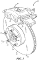
- FIG. 1 illustrates one embodiment of a braking system 20.
- Braking system 20 is a disc braking system that uses a rotatable brake element in the form of a rotor 30.
- the friction linings described herein may be adapted for or used with other braking systems, such as drum braking systems that use a metal drum as the rotatable brake element.
- the braking system 20 includes a brake pad 22 having a friction lining 24 and a backing plate 26.
- Caliper 28 holds the brake pad 22 and another brake pad (not shown) on opposing sides of rotor 30.
- the rotor 30 has an outer perimeter 32 and is connected to an axle hub via lug bolts 34.
- a vehicle wheel (not shown) can be attached over lug bolts 34 so that it rotates about central axis A.
- the illustrated rotor 30 is ventilated; however, this is not necessary as any operable rotor design may be employed, such as generally planar rotors or slotted rotors, to cite a few examples.
- the friction linings 24 of the brake pads 22 are clamped against opposing sides of the rotor 30 such that the friction surface of each friction lining bears against a side of the rotor to inhibit rotation of the rotor and, thus, the vehicle wheel.
- FIGS. 2 and 3 show brake pads 22 that may be used with a braking system, such as braking system 20.
- the brake pad 22 includes friction lining 24 that is attached to backing plate 26.
- the friction lining 24 is attached to a steel backing plate 26.
- the friction lining may be co-molded or otherwise formed with a backing plate, such as a composite backing plate.
- the friction lining 24 and backing plate 26 extend lengthwise with a length L in a horizontal direction that generally matches the circumferential direction of the rotor 30 when in use as shown in FIG. 1 . They also extend vertically with a height H that matches the radial direction of the rotor.
- the friction lining 24 comprises a body of solid friction material which includes a friction surface 36 that is clamped against a rotor, such as rotor 30, to inhibit rotation of a vehicle wheel during operation.
- the friction lining 24 has various airflow features formed in the friction surface 36.
- the airflow features such as one or more horizontal slots 38a, 38b (collectively, 38) and a vortex zone 40, may help facilitate or direct airflow to cool the friction lining 24.
- Airflow features may be formed in the friction surface by machining the features in the friction surface of a previously manufactured or partially manufactured friction lining, or they may be molded in depending on the desired manufacturing method and/or the type of material used for the friction lining.
- the friction lining 24 may or may not include other features, such as chamfers 42 or different configurations for outer perimeter 44.
- the horizontal slots 38a, 38b each include two side walls 46, 48 and a bottom wall 50.
- the slots may have a curved shape, a U- or V-shape, or any other operable shape.
- the horizontal slots 38 may have a variable depth and/or a variable width. For example, decreasing the width or depth of the slot near the vortex zone 40 may result in a higher speed of airflow into the vortex zone 40 due to the Venturi effect.
- the friction lining 24 may include two horizontal slots 38a, 38b joined at the vortex zone 40.
- the two horizontal slots 38a, 38b together form a single lengthwise slot that generally spans the length L of the friction lining 24, interrupted by the vortex zone 40.
- the two slots 38a, 38b may be offset from each other with respect to the height H of the friction lining 24.
- the horizontal slot 38a closer to the top edge of the friction lining begins at the leading edge of the lining (i.e., at the location where points on the rotor surface first come into contact with the friction lining when braking during rotor rotation).
- the other offset horizontal slot 38b begins at the trailing edge of the lining and joins.
- the same brake pad 22 may be used on the other side of the rotor in which case the inner or lower slot 38b closest to the bottom edge of the friction lining 24 begins at the leading edge of the lining.
- the slot positions relative to the height H of the friction lining may be switched for this second brake pad.
- one or more horizontal slots generally extend across the length L of the friction lining, or two horizontal slots may be situated on either side of a vortex zone so they are generally aligned with respect to the height H of the friction lining.
- Other slot designs and configurations are certainly possible.
- the lengthwise extent of the horizontal slots 38 can vary depending on the particular friction lining.
- the lengthwise extent of the horizontal slots 38 may depend on the slot depth and/or the degree to which chamfer 42 is angled with respect to the friction surface 36.
- the horizontal slots 38 may extend to the outer perimeter 44 of the friction lining 24 if there are no chamfers or a slightly angled chamfer.
- one or more horizontal slots 38 may terminate within the chamfer if the angle to which the chamfer 42 relates to the friction surface 36 is higher. It may be preferable to avoid creating sharp points in the horizontal slots 38 toward the edge of the friction lining 24, as the material could chip during machining or during operation.
- the angle at which the slot terminates with an edge of the friction lining is greater than approximately 54°.
- the horizontal slots 38 may extend along one or more arcs.
- the arcs of each of the horizontal slots 38a, 38b mimic the outer circumference 32 of the rotor 30. That is, these arcs (which can be the same or somewhat different than each other) may have generally the same radius of curvature as the location on rotor 30 where the friction lining 24 contacts the rotor. As a result, the slots will be parallel to the outer perimeter 32 of the rotor 30 when installed.
- the horizontal slots 38 follow the curvature of the rotor 30 even though in some embodiments they may be designed such that, when installed, they do not have the exact same radius as rotor 30 at the point on the rotor where the slot is located or may have different curvatures than each other or may not share the same radial center point as that of the rotor.
- This configuration of an arced, horizontal slot may help facilitate airflow, as the rotor may work as a fan to pull air through the slots and vortex zone as it rotates past the friction lining.
- the horizontal slots may be configured to be generally in line with the rotational path of the spinning rotor and with the concomitant airflow produced by the rotor.
- the rotor may have fins or features that act as an air pump to help encourage airflow through the slots.
- the vortex zone 40 is a recess that includes an interior wall 52 that extends from the friction surface 36 into the body of the friction lining 24.
- the interior wall 52 may include a radial surface 54 and a depression surface (or bottom) 56.
- the depression surface 56 may be curved, planar, or have some sort of surface treatment, one or more dimples, etc.
- the interior wall 52 generally defines a conical recess extending from the friction surface 36 into the body of the friction lining 24.
- the conical recess is one of a number of different circular shapes that may be used for the interior wall 52 to help facilitate or encourage a circular airflow pattern that operates to cool the friction lining 24.
- the cone shape vortex zone depicted may have a truncated shape such that it has a circular, flat bottom 56, as shown. However, it is possible for the cone shape to end at a point or have more of a spherical configuration at the bottom 56.
- the interior wall 52, and more particularly, the radial surface 54 of the vortex zone 40 may be generally smooth, as shown in FIG. 2 , or may include various features such as circumferential grooves 58, as shown in FIG. 3 .
- the vortex zone 40 is located at a central region of the friction lining 24. And in at least some embodiments, the vortex zone 40 is situated at or near the center of the friction lining 24.
- the openings of the two slots 38a, 38b into the vortex zone 40 are offset by about 180° and provide entry/exit passages that are positioned substantially tangential relative to the vortex zone to help create the circulating airflow therein.
- these slots open in the vortex zone along non-intersecting paths at locations that are offset from each other. This, in conjunction with the circular shape of the vortex zone 40, may help to cause air entering the vortex zone from one of the slots to flow in a curved direction within the vortex zone before exiting via the other slot.
- each of the slots 38 i.e., side wall 46 of the upper horizontal slot 38a, and side wall 48 of the lower horizontal slot 38b
- the outermost edge or wall of each of the slots 38 can be located such that it meets the interior wall 52 of the vortex substantially at a tangent of the interior wall 52.
- FIGS. 4 and 5 are drawings of a friction lining 24 in accordance with one embodiment. In these figures and the remaining figures, certain reference numerals may be omitted for clarity purposes.
- FIG. 5 is a cross-sectional view of the friction lining 24 of FIG. 4 taken along line 5-5 in FIG. 4 .
- the vortex zone 40 is a conically shaped recess with a truncated bottom 56.
- the angle ⁇ of the vortex zone 40 in at least some embodiments, is between 25° and 35°, inclusive, and, as depicted in FIG. 5 , may be approximately 30°.
- the inner radial wall 54 and flat bottom 56 meet at a radiused corner.
- the depth Dvz may be between about 0.25 and 0.43 with an opening diameter d of between about 0.65 and 0.92 and the bottom 56 having a diameter of between about 0.08 and 0.12 with a radiused corner of between about 0.18 and 0.32.
- the depth Dvz may be between about 0.18 and 0.32 with an opening diameter d of between about 0.51 and 0.67 and the bottom 56 having a diameter of between about 0.08 and 0.1 with a radiused corner of between about 0.18 and 0.25.
- the depth Ds of the horizontal slot 38 as it relates to the depth Dvz of the vortex zone (i.e., the depth of the bottom 56 of the vortex zone from the friction surface 36). As shown, the depth Dvz (of the bottom 56 of vortex zone 40 from the friction surface 36) is greater than the depth Ds of the slot 38.
- the ratio of Ds to Dvz is between 1/2 and 3/4, inclusive, and in one particular embodiment, the ratio to Ds to Dvz is 2/3.
- the diameter d of the vortex zone 40 may be dependent on the thickness of the friction lining. For example, it may be preferable to have approximately 0.1 inches of friction material between the depression surface 56 and the side of the friction lining opposing the friction surface 36. Therefore, depending on the desired angle ⁇ and/or depth Dvz, the diameter d of the vortex zone 40 may be adjusted so as to ensure enough friction material is left between the depression surface 56 and the side of the friction lining opposing the friction surface 36.
- the diameter d may also depend on the height H of the friction lining 24.
- the diameter d may be between 38% and 55%, inclusive, of the height H of the friction lining 24. In some embodiments, the diameter d is between 40% and 45%, inclusive, of the height H of the friction lining 24. And in one particular embodiment, the diameter d is 44% of the height H of the friction lining 24.
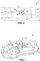
- FIG. 6 shows another embodiment of friction lining 24 having two horizontal slots 38a, 38b that terminate within the chamfers 42.
- the vortex zone 40 is located at the center point with respect to the height H of the friction lining as well as with respect to the length L of the friction lining.
- the horizontal slots 38a, 38b both terminate within the chamfers 42 instead of extending to the outer perimeter 44 of the friction lining 24.
- embodiments may include one or more vertical slots 60 in the friction lining 24 of a brake pad 22.
- two vertical slots 60 extend from the top and bottom of the outer perimeter 44 of the friction lining 24, respectively, to join, communicate, or otherwise terminate at the vortex zone 40.
- vertical slots 60 may include side walls 64, 66 and a bottom wall 68. The same variations, alternatives, configurations, etc. described above with respect to the horizontal slots are also applicable with respect to vertical slots.
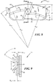
- FIGS. 8 and 9 are drawings of another embodiment of brake pad 22 having two horizontal slots 38a, 38b and two vertical slots 60 which all converge at vortex zone 40.
- FIG. 9 is a cross-sectional view of the friction lining 24 of FIG. 8 taken along line 9-9 of FIG. 8 .
- the arc of the top edge of the outer perimeter 44 of the friction lining 24 is generally defined by radius R FL .
- the horizontal slots 38a, 38b each have an arc that is generally defined by a radius R S1 and R S2 , respectively.
- the arcs defined by the radii R FL , R S1 , and R S2 are concentric, but need not be in at least some embodiments.
- the arcs defined by the radii R FL , R S1 , and R S2 may be concentric with the outer perimeter 32 of the rotor 30 in braking system 20. It will be appreciated by those skilled in the art that in other embodiments this concentricity is not required and that therefore the center points of the radii of the slots 38a, 38b may be different than each other or different than that of either the top edge of perimeter 44 or that of the rotor outer perimeter 32 once installed.
- FIG. 8 also shows that the horizontal slot 38b may define an angle ⁇ with the outer perimeter 44 of the friction lining 24.
- angle ⁇ is greater than or equal to 54°.
- the vertical slots 60 may define an angle ⁇ with respect to the center line of the friction lining. In this embodiment, angle ⁇ is 20° but may vary depending on the particular slot configuration.
- FIG. 9 shows that the radial surface 54 of the interior wall 52 of the vortex zone 40 can form an angle ⁇ with the friction surface 36 of the friction lining 24. In the illustrated embodiment, the angle ⁇ is 60°, but the angle ⁇ may be between 50° and 70°, inclusive.
- FIG. 9 also varies from the previously illustrated cross-sectional view of friction lining 24 in that the slot depth D S is 2/3 of the vortex zone depth D VZ .
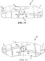
- FIGS. 10-13 illustrate friction linings 24 having various configurations for the outer perimeter 44, horizontal slots 38a, 38b, and chamfers 42.
- two pairs of horizontal slots 38 and two pairs of vertical slots 60 intersect or otherwise join at the vortex zone 40, which is centrally located with respect to the friction surface 36 and friction lining 24 in general.
- the horizontal slots 38a, 38b each extend all the way through the chamfer 42 to the outer perimeter 44.
- one horizontal slot 38b ends in the chamfer 42 while the other horizontal slot 38a extends to the outer perimeter 44.
- both horizontal slots 38a, 38b end prior to the outer perimeter 44.
- both horizontal slots 38a, 38b end at the outer perimeter 44, with one slot 38a ending in the chamfer 42 and the other slot 38b generally ending at the edge of the friction surface 36.
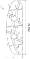
- FIG. 14 shows a friction lining 24 having two vortex zones 40 located in a central region of the solid body and being joined by a connecting slot 70.
- This particular embodiment includes two horizontal slots 38a, 38b extending from their respective side edge of the outer perimeter 44 of the friction lining 24 to one of the two vortex zones 40, respectively.
- Each vortex zone 40 includes a pair of vertical slots 60 extending from each vortex zone to the top and bottom of the outer perimeter 44 of the friction lining 24, respectively.
- Connecting slot 70 is situated between the two vortex zones 40. Connecting slot 70 may be straight as shown, or it may have an arced configuration.
- FIGS. 15 and 16 are images of brake pads 22 that were subject to testing to show the airflow pattern across the friction lining 24.
- FIG. 15 shows the inner pad
- FIG. 16 shows the outer pad, where "inner” and “outer” refer to the position of the friction lining relative to brake pad position in the caliper.
- the arrows 72 which represent the airflow are generally in line with the rotor rotation (i.e., the left side of FIG. 15 represents the leading edge while the right side of FIG. 16 represents the leading edge).
- a colored, fine particulate matter (illustrated as shaded areas 74 and 76, described below) was sprayed toward the spinning rotor surface 180° opposite of the caliper whereupon the moving airflow concomitant with the spinning rotor carried the dust cloud into the friction linings of the depicted brake pad embodiments.
- the testing showed that the colored, fine particulate matter was blown and focused toward contact point 74 on the radial surface 54 of the interior wall 52 of the vortex zone 40.
- the colored, fine particulate matter then left a trailing edge 76 along the radial surface 54 as airflow continued in a circular fashion within in the vortex zone 40.
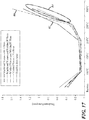
- FIG. 17 is a graph showing wear testing results for various types of friction linings.
- 80 represents a friction lining with a vortex zone but without slots
- 82 represents a friction lining with no airflow features
- 84 (circled group) represent friction linings having a vortex zone and various slot configurations.
- Lower thickness loss at a given temperature may be generally preferred.
- FIG. 17 shows that the inclusion of airflow features such as vortex holes and slots in the friction linings has a cooling effect that reduces wear, and may ultimately increase the overall brake pad life.
Landscapes
- Engineering & Computer Science (AREA)
- General Engineering & Computer Science (AREA)
- Mechanical Engineering (AREA)
- Braking Arrangements (AREA)
Claims (13)
- Reibbelag (24) für einen Bremsklotz (22), umfassend:
einen Festkörper aus Reibmaterial mit einer Vielzahl von Schlitzen (38a, 38b), die an einer Wirbelzone (40) verbunden sind, wobei die Wirbelzone eine Ausnehmung aufweist, die sich von einer Reibfläche (36) des Festkörpers nach unten in den Festkörper erstreckt, wobei mindestens einer der Schlitze ein bogenförmiger horizontaler Schlitz (38a, 38b) ist, der sich entlang einer Länge (L) des Reibbelags erstreckt, und wobei die Vielzahl von Schlitzen mindestens einen ersten und einen zweiten Schlitz aufweist, wobei sich die Schlitze entlang sich nicht schneidender Pfade an voneinander versetzten Stellen in die Wirbelzone öffnen. - Reibbelag (24) nach Anspruch 1, wobei die Ausnehmung eine Kreisform hat und der erste und der zweite Schlitz (38a, 38b) sich jeweils in die Wirbelzone (40) in einer im Wesentlichen tangentialen Richtung relativ zu der Kreisform der Ausnehmung öffnen, um dadurch tangentiale Eintritts-/Austrittspassagen zu schaffen, so dass Luft, die aus einem der Schlitze in die Wirbelzone (40) eintritt, in einer gekrümmten Richtung innerhalb der Wirbelzone strömt, bevor sie über den anderen Schlitz austritt.
- Reibbelag (24) nach Anspruch 1, wobei mindestens einer der Vielzahl von Schlitzen (38a, 38b) eine andere Tiefe oder Breite als ein anderer der Vielzahl von Schlitzen aufweist.
- Reibbelag (24) nach Anspruch 1, wobei die bogenförmigen Schlitze (38a, 38b) in Bezug auf eine Höhe (H) des Festkörpers gegeneinander versetzt sind.
- Reibbelag (24) nach Anspruch 1, wobei die Vielzahl von Schlitzen (38a, 38b) so konfiguriert ist, dass sie einen kreisförmigen Luftstrom innerhalb der Wirbelzone (40) erleichtert.
- Reibbelag (24) nach Anspruch 1, wobei der Festkörper eine Höhe (H) über die Reibfläche (36) des Festkörpers hat und die Wirbelzone (40) einen Durchmesser (d) an der Reibfläche hat, der zwischen 38 % bis 55 %, jeweils einschließlich, der Höhe beträgt.
- Reibbelag (24) nach Anspruch 6, wobei die Wirbelzone (40) sich von der Reibfläche (36) nach unten in den Festkörper zu einer Vertiefungsfläche (56) in einer Tiefe (DVZ) unterhalb der Reibfläche erstreckt, und wobei die Dicke des Festkörpers an der Vertiefungsfläche etwa 0,1 Zoll beträgt.
- Reibbelag (24) nach Anspruch 1, wobei mindestens einer der Schlitze (38a, 38b) eine Tiefe (DS) von der Reibfläche (36) des Festkörpers aufweist, die zwischen 50 % und 75 %, jeweils einschließlich, einer Tiefe (DVZ) der Wirbelzone (40) von der Reibfläche beträgt.
- Bremssystem (20), mit:einem Rotor (30) mit einer Scheibenform mit gegenüberliegenden Seiten, die sich radial zu einem äußeren Umfang (32) erstrecken; undeinem Bremsklotz (22), der einen Reibbelag (24) aufweist und relativ zu dem Rotor so angeordnet ist, dass eine Reibfläche (36) des Reibbelags an einer der Seiten des Rotors anliegt, um eine Drehung des Rotors im Betrieb zu verhindern;wobei der Reibbelag einen bogenförmigen horizontalen Schlitz (38) aufweist, der aus zwei versetzten Schlitzen (38a, 38b) gebildet ist, die in einer Wirbelzone (40) miteinander verbunden sind, die die beiden versetzten Schlitze (38a, 38b) in einem zentralen Bereich des Reibbelags verbindet, so dass im Gebrauch ein in einen der versetzten Schlitze eintretender Luftstrom über den anderen der versetzten Schlitze austritt, wobei die Wirbelzone eine Ausnehmung aufweist, die sich von der Reibfläche des Festkörpers nach unten in den Festkörper erstreckt; undwobei sich jeder der versetzten Schlitze entlang eines Bogens erstreckt, der im Gebrauch einem Weg eines Punktes auf dem Rotor folgt.
- Bremssystem (20) nach Anspruch 9, wobei die Wirbelzone (40) eine kreisförmige Ausnehmung aufweist, die sich von der Reibfläche (36) des Reibbelags (24) in den Festkörper nach unten zu einem Boden (56) der Ausnehmung erstreckt,wobei der Boden eine Tiefe von der Oberfläche des Festkörpers hat, die größer ist als eine Tiefe jedes der versetzten Schlitze (38a, 38b), undwobei sich die versetzten Schlitze in die Ausnehmung in einer im Wesentlichen tangentialen Richtung relativ zu der Kreisform der Ausnehmung öffnen, wodurch Luft, die aus einem der versetzten Schlitze in die Ausnehmung eintritt, in einer gekrümmten Richtung innerhalb der Ausnehmung strömt, bevor sie die Ausnehmung über den anderen versetzten Schlitz verlässt.
- Bremssystem (20) nach Anspruch 9, wobei der Reibbelag (24) eine sich radial erstreckende Höhe (H) aufweist und die Wirbelzone (40) einen Durchmesser (d) an der Reibfläche (36) hat, der zwischen 38 % bis 55 %, jeweils einschließlich, der Höhe beträgt.
- Bremssystem (20) nach Anspruch 9, wobei der Reibbelag (24) ein Paar von sich vertikal erstreckenden, versetzten Schlitzen (60) aufweist, die sich jeweils von einem Rand (44) des Reibbelags bis zu der Wirbelzone (40) erstrecken.
- Bremssystem (20) nach Anspruch 9, wobei sich der horizontale Schlitz (38) über eine gesamte horizontale Länge (L) des Reibbelags (24) erstreckt.
Applications Claiming Priority (3)
| Application Number | Priority Date | Filing Date | Title |
|---|---|---|---|
| US201562268826P | 2015-12-17 | 2015-12-17 | |
| US15/378,961 US10962072B2 (en) | 2015-12-17 | 2016-12-14 | Friction lining and brake pad for a braking system |
| PCT/US2016/067367 WO2017106776A1 (en) | 2015-12-17 | 2016-12-16 | Friction lining and brake pad for a braking system |
Publications (3)
| Publication Number | Publication Date |
|---|---|
| EP3394473A1 EP3394473A1 (de) | 2018-10-31 |
| EP3394473A4 EP3394473A4 (de) | 2019-08-07 |
| EP3394473B1 true EP3394473B1 (de) | 2020-11-11 |
Family
ID=59057769
Family Applications (1)
| Application Number | Title | Priority Date | Filing Date |
|---|---|---|---|
| EP16876861.2A Revoked EP3394473B1 (de) | 2015-12-17 | 2016-12-16 | Reibauskleidung und bremsbelag für eine bremsanlage |
Country Status (8)
| Country | Link |
|---|---|
| US (1) | US10962072B2 (de) |
| EP (1) | EP3394473B1 (de) |
| JP (1) | JP6676169B2 (de) |
| KR (1) | KR20180108579A (de) |
| CN (1) | CN109073014B (de) |
| BR (1) | BR112018012080A2 (de) |
| RU (1) | RU2709149C1 (de) |
| WO (1) | WO2017106776A1 (de) |
Families Citing this family (9)
| Publication number | Priority date | Publication date | Assignee | Title |
|---|---|---|---|---|
| KR102276892B1 (ko) * | 2014-05-16 | 2021-07-14 | 프레니 브렘보우 에스.피.에이. | 마찰 조립체, 브레이크 캘리퍼 및 이의 제조 방법 |
| FR3057040B1 (fr) | 2016-10-05 | 2019-05-03 | Tallano Technologie | Plaquette de frein et ensemble de frein a captation de particules |
| FR3076876B1 (fr) * | 2018-01-17 | 2020-01-03 | Tallano Technologie | Plaquette de frein pour ensemble de frein a disque comprenant une rainure d'aspiration en zone avant et une zone avant chanfreinee |
| US20190346000A1 (en) * | 2018-05-09 | 2019-11-14 | Bremskerl North America, Inc. | Grooved Disc Brake |
| CN109404449A (zh) * | 2019-01-03 | 2019-03-01 | 倪岚霖 | 一种汽车刹车片 |
| FR3098178B1 (fr) * | 2019-07-03 | 2021-07-30 | Tallano Tech | Système de sécurisation de pièce montée sur porte-semelle |
| KR20220059018A (ko) | 2020-11-02 | 2022-05-10 | 주식회사 대신브레이크 | 마모 디스크에 장착 가능한 자동차용 브레이크 패드 |
| EP4345332A1 (de) * | 2022-09-27 | 2024-04-03 | KNORR-BREMSE Systeme für Nutzfahrzeuge GmbH | Bremsbelag und scheibenbremse mit dem bremsbelag |
| FR3158344A1 (fr) * | 2024-01-15 | 2025-07-18 | Tallano Technologies | Système de freinage |
Citations (6)
| Publication number | Priority date | Publication date | Assignee | Title |
|---|---|---|---|---|
| WO1995017612A1 (en) | 1993-12-22 | 1995-06-29 | Pbr Automotive Pty. Ltd. | A disc brake assembly |
| DE4401846A1 (de) | 1994-01-22 | 1995-07-27 | Teves Gmbh Alfred | Bremsbelag für Scheibenbremse |
| WO1996007034A1 (en) | 1994-08-26 | 1996-03-07 | Francis Edward Parsons | Wet disc brake |
| JP2008281060A (ja) | 2007-05-09 | 2008-11-20 | Toyota Motor Corp | ブレーキパッド |
| CN101749346A (zh) | 2008-12-09 | 2010-06-23 | 温芫鋐 | 煞车块结构 |
| JP2013144585A (ja) | 2012-01-13 | 2013-07-25 | Mitsubishi Electric Corp | エレベータ巻上機用のディスクブレーキ装置及び粉塵除去方法 |
Family Cites Families (42)
| Publication number | Priority date | Publication date | Assignee | Title |
|---|---|---|---|---|
| US2150186A (en) * | 1936-09-16 | 1939-03-14 | Raybestos Manhattan Inc | Fibrous friction element |
| US2438483A (en) * | 1944-07-08 | 1948-03-23 | American Steel Foundries | Brake shoe and head arrangement |
| US2849092A (en) | 1954-09-09 | 1958-08-26 | Robert W Matthews | Air cooled brake shoe |
| DE1425202A1 (de) * | 1961-09-12 | 1968-10-24 | Celestino Benini | Backenbremse,insbesondere Fahr?eugbremse |
| GB1006500A (en) | 1963-01-03 | 1965-10-06 | Falk Corp | Coupling |
| SE7414359L (sv) | 1974-11-15 | 1976-05-17 | Bofors Ab | Sett att kyla en vat lamellkoppling jemte herfor avsedd kopplingslamell |
| FR2580441B1 (fr) * | 1985-04-15 | 1989-01-27 | Labavia | Perfectionnements aux rotors induits des ralentisseurs electromagnetiques |
| JPH0248769B2 (ja) * | 1989-03-29 | 1990-10-26 | Toyo Kaabon Kk | Bureekipatsudo |
| ES2129045T3 (es) * | 1991-10-11 | 1999-06-01 | Francis Edward Parsons | Frenos de disco de funcionamiento en estado humedo. |
| CN2182903Y (zh) | 1993-01-03 | 1994-11-16 | 赵明德 | 五块式散热型石棉刹车片装置 |
| US5816901A (en) * | 1993-04-09 | 1998-10-06 | Sirany; Dallas R. | Method of resurfacing a vehicles's braking rotors and drums |
| US5388675A (en) | 1994-06-23 | 1995-02-14 | Westinghouse Air Brake Company | Backing plate for disc brake pad |
| RU2098686C1 (ru) | 1996-07-01 | 1997-12-10 | Открытое акционерное общество "ГАЗ" | Тормозная колодка дискового тормозного механизма |
| JP3909122B2 (ja) | 1997-07-22 | 2007-04-25 | 曙ブレーキ工業株式会社 | ディスクブレーキ用パッド |
| JP2000145848A (ja) | 1998-11-11 | 2000-05-26 | Sumitomo Electric Ind Ltd | ディスクブレーキパッド |
| RU2154207C1 (ru) | 1999-07-19 | 2000-08-10 | Открытое акционерное общество Научно-исследовательский и конструкторско-технологический институт асбестовых технических изделий - Фирма ТИИР | Колодка дискового тормоза |
| US6478130B2 (en) * | 2000-12-22 | 2002-11-12 | Eaton Corporation | Clutch friction button |
| DE10200455A1 (de) | 2002-01-09 | 2003-07-24 | Tmd Friction Gmbh | Bremsscheibe mit seitlichen Öffnungen |
| FR2853378B1 (fr) | 2003-04-02 | 2006-03-10 | Carbone Lorraine Composants | Plaquettes de frein a disque ventilees |
| KR20050100980A (ko) | 2004-04-16 | 2005-10-20 | 한국델파이주식회사 | 차량용 캘리퍼 브레이크의 패드 구조 |
| US7267319B2 (en) * | 2004-11-09 | 2007-09-11 | General Electric Company | Low-friction slide-plates for rotary machines |
| JP4446897B2 (ja) * | 2005-01-17 | 2010-04-07 | 日立オートモティブシステムズ株式会社 | 内燃機関のバルブタイミング制御装置 |
| US20060225975A1 (en) * | 2005-04-07 | 2006-10-12 | Raymond Pfaff | Drum brake pad |
| JP2007024286A (ja) | 2005-07-21 | 2007-02-01 | Nissan Motor Co Ltd | ディスクブレーキパッド |
| DE102006031035A1 (de) | 2006-07-05 | 2008-01-10 | Zf Friedrichshafen Ag | Reibscheibe für eine nasslaufende Kupplung für ein Fahrzeug |
| US8151433B2 (en) | 2007-08-01 | 2012-04-10 | Federal-Mogul Products, Inc. | Method of making disc brake pads |
| DE102007037612A1 (de) | 2007-08-09 | 2009-02-12 | Continental Automotive Gmbh | Abrasive Reibfläche |
| CA130271S (en) * | 2009-04-08 | 2010-04-30 | Satisfied Brake Products Inc | Brake pad |
| IT1395120B1 (it) * | 2009-07-29 | 2012-09-05 | Freni Brembo Spa | Fascia di frenatura e disco per freno a disco |
| US9215519B2 (en) * | 2010-07-30 | 2015-12-15 | Invensense, Inc. | Reduced footprint microphone system with spacer member having through-hole |
| US8485323B2 (en) | 2010-10-08 | 2013-07-16 | Akebono Brake Corporation | Caliper assembly for disc brake system |
| CN202176648U (zh) | 2011-08-31 | 2012-03-28 | 昆山新力精密五金有限公司 | 新型盘式刹车片 |
| JP2014070651A (ja) | 2012-09-27 | 2014-04-21 | Advics Co Ltd | ブレーキパッド |
| CN102927163A (zh) * | 2012-11-15 | 2013-02-13 | 安徽合力股份有限公司 | 叉车驱动桥用湿式制动器 |
| CN103967982A (zh) * | 2013-02-01 | 2014-08-06 | 王志扬 | 来令片的散热背板结构 |
| CN203374713U (zh) | 2013-06-03 | 2014-01-01 | 芜湖东正汽车工业有限公司 | 一种多工况散热型刹车片 |
| CN203604518U (zh) * | 2013-10-21 | 2014-05-21 | 芜湖东正汽车工业有限公司 | 一种散热型耐磨刹车片 |
| CN103591197B (zh) * | 2013-10-21 | 2015-12-23 | 芜湖东正汽车工业有限公司 | 一种散热型耐磨刹车片 |
| US20150159715A1 (en) * | 2013-12-06 | 2015-06-11 | Bendix Commercial Vehicle Systems Llc | Brake pads for a vehicle braking assembly |
| CN103883653B (zh) | 2014-02-07 | 2016-06-15 | 江苏恒力制动器制造有限公司 | 一种用于盘式制动器的刹车片 |
| CN106536964B (zh) * | 2014-06-13 | 2019-03-01 | 辉门汽车零部件公司 | 用于车辆的盘式制动块 |
| CN104832557A (zh) | 2015-04-22 | 2015-08-12 | 安徽龙行密封件有限公司 | 一种离合器摩擦片 |
-
2016
- 2016-12-14 US US15/378,961 patent/US10962072B2/en active Active
- 2016-12-16 JP JP2018531380A patent/JP6676169B2/ja not_active Expired - Fee Related
- 2016-12-16 RU RU2018125886A patent/RU2709149C1/ru active
- 2016-12-16 EP EP16876861.2A patent/EP3394473B1/de not_active Revoked
- 2016-12-16 BR BR112018012080A patent/BR112018012080A2/pt not_active Application Discontinuation
- 2016-12-16 KR KR1020187018991A patent/KR20180108579A/ko not_active Abandoned
- 2016-12-16 WO PCT/US2016/067367 patent/WO2017106776A1/en not_active Ceased
- 2016-12-16 CN CN201680082086.4A patent/CN109073014B/zh active Active
Patent Citations (6)
| Publication number | Priority date | Publication date | Assignee | Title |
|---|---|---|---|---|
| WO1995017612A1 (en) | 1993-12-22 | 1995-06-29 | Pbr Automotive Pty. Ltd. | A disc brake assembly |
| DE4401846A1 (de) | 1994-01-22 | 1995-07-27 | Teves Gmbh Alfred | Bremsbelag für Scheibenbremse |
| WO1996007034A1 (en) | 1994-08-26 | 1996-03-07 | Francis Edward Parsons | Wet disc brake |
| JP2008281060A (ja) | 2007-05-09 | 2008-11-20 | Toyota Motor Corp | ブレーキパッド |
| CN101749346A (zh) | 2008-12-09 | 2010-06-23 | 温芫鋐 | 煞车块结构 |
| JP2013144585A (ja) | 2012-01-13 | 2013-07-25 | Mitsubishi Electric Corp | エレベータ巻上機用のディスクブレーキ装置及び粉塵除去方法 |
Also Published As
| Publication number | Publication date |
|---|---|
| WO2017106776A1 (en) | 2017-06-22 |
| CN109073014A (zh) | 2018-12-21 |
| EP3394473A4 (de) | 2019-08-07 |
| BR112018012080A2 (pt) | 2018-11-27 |
| RU2709149C1 (ru) | 2019-12-16 |
| JP6676169B2 (ja) | 2020-04-08 |
| JP2018537635A (ja) | 2018-12-20 |
| EP3394473A1 (de) | 2018-10-31 |
| KR20180108579A (ko) | 2018-10-04 |
| CN109073014B (zh) | 2021-07-09 |
| US20170175838A1 (en) | 2017-06-22 |
| US10962072B2 (en) | 2021-03-30 |
Similar Documents
| Publication | Publication Date | Title |
|---|---|---|
| EP3394473B1 (de) | Reibauskleidung und bremsbelag für eine bremsanlage | |
| CN110062854B (zh) | 通风式制动盘 | |
| US10024377B2 (en) | Ventilated brake disc | |
| US6446770B2 (en) | Brake rotor having an array of grooves formed thereon | |
| US9022183B2 (en) | Self-centering wet clutch or brake plate | |
| US10794440B2 (en) | Internally ventilated brake disk | |
| US6053290A (en) | Dual web brake rotor | |
| JP4348132B2 (ja) | ブレーキロータ | |
| EP0906521B1 (de) | Scheibenbremsrotor | |
| EP0870125B1 (de) | Belüftete bremsscheibe mit schwingungsunterdrückung | |
| JPS6020844Y2 (ja) | デイスクブレ−キ用デイスク | |
| US12535112B2 (en) | Brake disk with protrusions | |
| CN121240998A (zh) | 用于车轮制动盘的摩擦环和用于轨道车辆的车轮制动盘 |
Legal Events
| Date | Code | Title | Description |
|---|---|---|---|
| STAA | Information on the status of an ep patent application or granted ep patent |
Free format text: STATUS: THE INTERNATIONAL PUBLICATION HAS BEEN MADE |
|
| PUAI | Public reference made under article 153(3) epc to a published international application that has entered the european phase |
Free format text: ORIGINAL CODE: 0009012 |
|
| STAA | Information on the status of an ep patent application or granted ep patent |
Free format text: STATUS: REQUEST FOR EXAMINATION WAS MADE |
|
| 17P | Request for examination filed |
Effective date: 20180704 |
|
| AK | Designated contracting states |
Kind code of ref document: A1 Designated state(s): AL AT BE BG CH CY CZ DE DK EE ES FI FR GB GR HR HU IE IS IT LI LT LU LV MC MK MT NL NO PL PT RO RS SE SI SK SM TR |
|
| AX | Request for extension of the european patent |
Extension state: BA ME |
|
| DAV | Request for validation of the european patent (deleted) | ||
| DAX | Request for extension of the european patent (deleted) | ||
| A4 | Supplementary search report drawn up and despatched |
Effective date: 20190704 |
|
| RIC1 | Information provided on ipc code assigned before grant |
Ipc: F16D 65/78 20060101AFI20190628BHEP |
|
| REG | Reference to a national code |
Ref country code: DE Ref legal event code: R079 Ref document number: 602016047866 Country of ref document: DE Free format text: PREVIOUS MAIN CLASS: F16D0069000000 Ipc: F16D0065780000 |
|
| RIC1 | Information provided on ipc code assigned before grant |
Ipc: F16D 65/78 20060101AFI20200429BHEP |
|
| GRAP | Despatch of communication of intention to grant a patent |
Free format text: ORIGINAL CODE: EPIDOSNIGR1 |
|
| STAA | Information on the status of an ep patent application or granted ep patent |
Free format text: STATUS: GRANT OF PATENT IS INTENDED |
|
| INTG | Intention to grant announced |
Effective date: 20200609 |
|
| GRAS | Grant fee paid |
Free format text: ORIGINAL CODE: EPIDOSNIGR3 |
|
| GRAA | (expected) grant |
Free format text: ORIGINAL CODE: 0009210 |
|
| STAA | Information on the status of an ep patent application or granted ep patent |
Free format text: STATUS: THE PATENT HAS BEEN GRANTED |
|
| AK | Designated contracting states |
Kind code of ref document: B1 Designated state(s): AL AT BE BG CH CY CZ DE DK EE ES FI FR GB GR HR HU IE IS IT LI LT LU LV MC MK MT NL NO PL PT RO RS SE SI SK SM TR |
|
| REG | Reference to a national code |
Ref country code: GB Ref legal event code: FG4D |
|
| REG | Reference to a national code |
Ref country code: CH Ref legal event code: EP |
|
| REG | Reference to a national code |
Ref country code: AT Ref legal event code: REF Ref document number: 1333776 Country of ref document: AT Kind code of ref document: T Effective date: 20201115 |
|
| REG | Reference to a national code |
Ref country code: DE Ref legal event code: R096 Ref document number: 602016047866 Country of ref document: DE |
|
| REG | Reference to a national code |
Ref country code: IE Ref legal event code: FG4D |
|
| REG | Reference to a national code |
Ref country code: NL Ref legal event code: MP Effective date: 20201111 |
|
| REG | Reference to a national code |
Ref country code: AT Ref legal event code: MK05 Ref document number: 1333776 Country of ref document: AT Kind code of ref document: T Effective date: 20201111 |
|
| PG25 | Lapsed in a contracting state [announced via postgrant information from national office to epo] |
Ref country code: GR Free format text: LAPSE BECAUSE OF FAILURE TO SUBMIT A TRANSLATION OF THE DESCRIPTION OR TO PAY THE FEE WITHIN THE PRESCRIBED TIME-LIMIT Effective date: 20210212 Ref country code: FI Free format text: LAPSE BECAUSE OF FAILURE TO SUBMIT A TRANSLATION OF THE DESCRIPTION OR TO PAY THE FEE WITHIN THE PRESCRIBED TIME-LIMIT Effective date: 20201111 Ref country code: NO Free format text: LAPSE BECAUSE OF FAILURE TO SUBMIT A TRANSLATION OF THE DESCRIPTION OR TO PAY THE FEE WITHIN THE PRESCRIBED TIME-LIMIT Effective date: 20210211 Ref country code: RS Free format text: LAPSE BECAUSE OF FAILURE TO SUBMIT A TRANSLATION OF THE DESCRIPTION OR TO PAY THE FEE WITHIN THE PRESCRIBED TIME-LIMIT Effective date: 20201111 Ref country code: PT Free format text: LAPSE BECAUSE OF FAILURE TO SUBMIT A TRANSLATION OF THE DESCRIPTION OR TO PAY THE FEE WITHIN THE PRESCRIBED TIME-LIMIT Effective date: 20210311 |
|
| PG25 | Lapsed in a contracting state [announced via postgrant information from national office to epo] |
Ref country code: SE Free format text: LAPSE BECAUSE OF FAILURE TO SUBMIT A TRANSLATION OF THE DESCRIPTION OR TO PAY THE FEE WITHIN THE PRESCRIBED TIME-LIMIT Effective date: 20201111 Ref country code: AT Free format text: LAPSE BECAUSE OF FAILURE TO SUBMIT A TRANSLATION OF THE DESCRIPTION OR TO PAY THE FEE WITHIN THE PRESCRIBED TIME-LIMIT Effective date: 20201111 Ref country code: BG Free format text: LAPSE BECAUSE OF FAILURE TO SUBMIT A TRANSLATION OF THE DESCRIPTION OR TO PAY THE FEE WITHIN THE PRESCRIBED TIME-LIMIT Effective date: 20210211 Ref country code: IS Free format text: LAPSE BECAUSE OF FAILURE TO SUBMIT A TRANSLATION OF THE DESCRIPTION OR TO PAY THE FEE WITHIN THE PRESCRIBED TIME-LIMIT Effective date: 20210311 Ref country code: LV Free format text: LAPSE BECAUSE OF FAILURE TO SUBMIT A TRANSLATION OF THE DESCRIPTION OR TO PAY THE FEE WITHIN THE PRESCRIBED TIME-LIMIT Effective date: 20201111 Ref country code: PL Free format text: LAPSE BECAUSE OF FAILURE TO SUBMIT A TRANSLATION OF THE DESCRIPTION OR TO PAY THE FEE WITHIN THE PRESCRIBED TIME-LIMIT Effective date: 20201111 |
|
| REG | Reference to a national code |
Ref country code: LT Ref legal event code: MG9D |
|
| PG25 | Lapsed in a contracting state [announced via postgrant information from national office to epo] |
Ref country code: HR Free format text: LAPSE BECAUSE OF FAILURE TO SUBMIT A TRANSLATION OF THE DESCRIPTION OR TO PAY THE FEE WITHIN THE PRESCRIBED TIME-LIMIT Effective date: 20201111 |
|
| PG25 | Lapsed in a contracting state [announced via postgrant information from national office to epo] |
Ref country code: SK Free format text: LAPSE BECAUSE OF FAILURE TO SUBMIT A TRANSLATION OF THE DESCRIPTION OR TO PAY THE FEE WITHIN THE PRESCRIBED TIME-LIMIT Effective date: 20201111 Ref country code: RO Free format text: LAPSE BECAUSE OF FAILURE TO SUBMIT A TRANSLATION OF THE DESCRIPTION OR TO PAY THE FEE WITHIN THE PRESCRIBED TIME-LIMIT Effective date: 20201111 Ref country code: CZ Free format text: LAPSE BECAUSE OF FAILURE TO SUBMIT A TRANSLATION OF THE DESCRIPTION OR TO PAY THE FEE WITHIN THE PRESCRIBED TIME-LIMIT Effective date: 20201111 Ref country code: EE Free format text: LAPSE BECAUSE OF FAILURE TO SUBMIT A TRANSLATION OF THE DESCRIPTION OR TO PAY THE FEE WITHIN THE PRESCRIBED TIME-LIMIT Effective date: 20201111 Ref country code: SM Free format text: LAPSE BECAUSE OF FAILURE TO SUBMIT A TRANSLATION OF THE DESCRIPTION OR TO PAY THE FEE WITHIN THE PRESCRIBED TIME-LIMIT Effective date: 20201111 Ref country code: LT Free format text: LAPSE BECAUSE OF FAILURE TO SUBMIT A TRANSLATION OF THE DESCRIPTION OR TO PAY THE FEE WITHIN THE PRESCRIBED TIME-LIMIT Effective date: 20201111 |
|
| REG | Reference to a national code |
Ref country code: CH Ref legal event code: PL |
|
| REG | Reference to a national code |
Ref country code: DE Ref legal event code: R026 Ref document number: 602016047866 Country of ref document: DE |
|
| PLBI | Opposition filed |
Free format text: ORIGINAL CODE: 0009260 |
|
| PLAX | Notice of opposition and request to file observation + time limit sent |
Free format text: ORIGINAL CODE: EPIDOSNOBS2 |
|
| PG25 | Lapsed in a contracting state [announced via postgrant information from national office to epo] |
Ref country code: MC Free format text: LAPSE BECAUSE OF FAILURE TO SUBMIT A TRANSLATION OF THE DESCRIPTION OR TO PAY THE FEE WITHIN THE PRESCRIBED TIME-LIMIT Effective date: 20201111 Ref country code: DK Free format text: LAPSE BECAUSE OF FAILURE TO SUBMIT A TRANSLATION OF THE DESCRIPTION OR TO PAY THE FEE WITHIN THE PRESCRIBED TIME-LIMIT Effective date: 20201111 |
|
| REG | Reference to a national code |
Ref country code: BE Ref legal event code: MM Effective date: 20201231 |
|
| 26 | Opposition filed |
Opponent name: VRI-VERBAND DER REIBBELAGINDUSTRIE E.V. Effective date: 20210810 |
|
| GBPC | Gb: european patent ceased through non-payment of renewal fee |
Effective date: 20210211 |
|
| PG25 | Lapsed in a contracting state [announced via postgrant information from national office to epo] |
Ref country code: AL Free format text: LAPSE BECAUSE OF FAILURE TO SUBMIT A TRANSLATION OF THE DESCRIPTION OR TO PAY THE FEE WITHIN THE PRESCRIBED TIME-LIMIT Effective date: 20201111 Ref country code: IE Free format text: LAPSE BECAUSE OF NON-PAYMENT OF DUE FEES Effective date: 20201216 Ref country code: NL Free format text: LAPSE BECAUSE OF FAILURE TO SUBMIT A TRANSLATION OF THE DESCRIPTION OR TO PAY THE FEE WITHIN THE PRESCRIBED TIME-LIMIT Effective date: 20201111 Ref country code: FR Free format text: LAPSE BECAUSE OF NON-PAYMENT OF DUE FEES Effective date: 20210111 Ref country code: IT Free format text: LAPSE BECAUSE OF FAILURE TO SUBMIT A TRANSLATION OF THE DESCRIPTION OR TO PAY THE FEE WITHIN THE PRESCRIBED TIME-LIMIT Effective date: 20201111 Ref country code: LU Free format text: LAPSE BECAUSE OF NON-PAYMENT OF DUE FEES Effective date: 20201216 |
|
| PG25 | Lapsed in a contracting state [announced via postgrant information from national office to epo] |
Ref country code: SI Free format text: LAPSE BECAUSE OF FAILURE TO SUBMIT A TRANSLATION OF THE DESCRIPTION OR TO PAY THE FEE WITHIN THE PRESCRIBED TIME-LIMIT Effective date: 20201111 Ref country code: CH Free format text: LAPSE BECAUSE OF NON-PAYMENT OF DUE FEES Effective date: 20201231 Ref country code: LI Free format text: LAPSE BECAUSE OF NON-PAYMENT OF DUE FEES Effective date: 20201231 |
|
| PLBB | Reply of patent proprietor to notice(s) of opposition received |
Free format text: ORIGINAL CODE: EPIDOSNOBS3 |
|
| PG25 | Lapsed in a contracting state [announced via postgrant information from national office to epo] |
Ref country code: GB Free format text: LAPSE BECAUSE OF NON-PAYMENT OF DUE FEES Effective date: 20210211 Ref country code: ES Free format text: LAPSE BECAUSE OF FAILURE TO SUBMIT A TRANSLATION OF THE DESCRIPTION OR TO PAY THE FEE WITHIN THE PRESCRIBED TIME-LIMIT Effective date: 20201111 |
|
| PGFP | Annual fee paid to national office [announced via postgrant information from national office to epo] |
Ref country code: DE Payment date: 20211117 Year of fee payment: 6 |
|
| RDAF | Communication despatched that patent is revoked |
Free format text: ORIGINAL CODE: EPIDOSNREV1 |
|
| REG | Reference to a national code |
Ref country code: DE Ref legal event code: R103 Ref document number: 602016047866 Country of ref document: DE Ref country code: DE Ref legal event code: R064 Ref document number: 602016047866 Country of ref document: DE |
|
| PG25 | Lapsed in a contracting state [announced via postgrant information from national office to epo] |
Ref country code: IS Free format text: LAPSE BECAUSE OF FAILURE TO SUBMIT A TRANSLATION OF THE DESCRIPTION OR TO PAY THE FEE WITHIN THE PRESCRIBED TIME-LIMIT Effective date: 20210311 Ref country code: TR Free format text: LAPSE BECAUSE OF FAILURE TO SUBMIT A TRANSLATION OF THE DESCRIPTION OR TO PAY THE FEE WITHIN THE PRESCRIBED TIME-LIMIT Effective date: 20201111 Ref country code: MT Free format text: LAPSE BECAUSE OF FAILURE TO SUBMIT A TRANSLATION OF THE DESCRIPTION OR TO PAY THE FEE WITHIN THE PRESCRIBED TIME-LIMIT Effective date: 20201111 Ref country code: CY Free format text: LAPSE BECAUSE OF FAILURE TO SUBMIT A TRANSLATION OF THE DESCRIPTION OR TO PAY THE FEE WITHIN THE PRESCRIBED TIME-LIMIT Effective date: 20201111 |
|
| PG25 | Lapsed in a contracting state [announced via postgrant information from national office to epo] |
Ref country code: MK Free format text: LAPSE BECAUSE OF FAILURE TO SUBMIT A TRANSLATION OF THE DESCRIPTION OR TO PAY THE FEE WITHIN THE PRESCRIBED TIME-LIMIT Effective date: 20201111 |
|
| RDAG | Patent revoked |
Free format text: ORIGINAL CODE: 0009271 |
|
| STAA | Information on the status of an ep patent application or granted ep patent |
Free format text: STATUS: PATENT REVOKED |
|
| PG25 | Lapsed in a contracting state [announced via postgrant information from national office to epo] |
Ref country code: BE Free format text: LAPSE BECAUSE OF NON-PAYMENT OF DUE FEES Effective date: 20201231 |
|
| REG | Reference to a national code |
Ref country code: CH Ref legal event code: PL |
|
| 27W | Patent revoked |
Effective date: 20220418 |
|
| REG | Reference to a national code |
Ref country code: FI Ref legal event code: MGE |
|
| P01 | Opt-out of the competence of the unified patent court (upc) registered |
Effective date: 20230528 |