EP3394671B1 - Adapterkit für kamerafilter - Google Patents
Adapterkit für kamerafilter Download PDFInfo
- Publication number
- EP3394671B1 EP3394671B1 EP16877046.9A EP16877046A EP3394671B1 EP 3394671 B1 EP3394671 B1 EP 3394671B1 EP 16877046 A EP16877046 A EP 16877046A EP 3394671 B1 EP3394671 B1 EP 3394671B1
- Authority
- EP
- European Patent Office
- Prior art keywords
- filter
- lens
- engagement
- diameter
- interfacing
- Prior art date
- Legal status (The legal status is an assumption and is not a legal conclusion. Google has not performed a legal analysis and makes no representation as to the accuracy of the status listed.)
- Active
Links
Images






Classifications
-
- G—PHYSICS
- G02—OPTICS
- G02B—OPTICAL ELEMENTS, SYSTEMS OR APPARATUS
- G02B7/00—Mountings, adjusting means, or light-tight connections, for optical elements
- G02B7/006—Filter holders
-
- G—PHYSICS
- G03—PHOTOGRAPHY; CINEMATOGRAPHY; ANALOGOUS TECHNIQUES USING WAVES OTHER THAN OPTICAL WAVES; ELECTROGRAPHY; HOLOGRAPHY
- G03B—APPARATUS OR ARRANGEMENTS FOR TAKING PHOTOGRAPHS OR FOR PROJECTING OR VIEWING THEM; APPARATUS OR ARRANGEMENTS EMPLOYING ANALOGOUS TECHNIQUES USING WAVES OTHER THAN OPTICAL WAVES; ACCESSORIES THEREFOR
- G03B11/00—Filters or other obturators specially adapted for photographic purposes
-
- G—PHYSICS
- G02—OPTICS
- G02B—OPTICAL ELEMENTS, SYSTEMS OR APPARATUS
- G02B7/00—Mountings, adjusting means, or light-tight connections, for optical elements
- G02B7/02—Mountings, adjusting means, or light-tight connections, for optical elements for lenses
- G02B7/022—Mountings, adjusting means, or light-tight connections, for optical elements for lenses lens and mount having complementary engagement means, e.g. screw/thread
-
- G—PHYSICS
- G03—PHOTOGRAPHY; CINEMATOGRAPHY; ANALOGOUS TECHNIQUES USING WAVES OTHER THAN OPTICAL WAVES; ELECTROGRAPHY; HOLOGRAPHY
- G03B—APPARATUS OR ARRANGEMENTS FOR TAKING PHOTOGRAPHS OR FOR PROJECTING OR VIEWING THEM; APPARATUS OR ARRANGEMENTS EMPLOYING ANALOGOUS TECHNIQUES USING WAVES OTHER THAN OPTICAL WAVES; ACCESSORIES THEREFOR
- G03B17/00—Details of cameras or camera bodies; Accessories therefor
- G03B17/56—Accessories
- G03B17/566—Accessory clips, holders, shoes to attach accessories to camera
-
- H—ELECTRICITY
- H04—ELECTRIC COMMUNICATION TECHNIQUE
- H04N—PICTORIAL COMMUNICATION, e.g. TELEVISION
- H04N23/00—Cameras or camera modules comprising electronic image sensors; Control thereof
- H04N23/50—Constructional details
- H04N23/55—Optical parts specially adapted for electronic image sensors; Mounting thereof
Definitions
- the present disclosure generally relates to accessories for photography and videography, and more particularly to adaptor kits for mounting a camera filter.
- a camera filter is an accessory that is placed over the camera lens along the optical path between the camera lens and the scene captured.
- the camera filter is formed of a material that modifies the properties of light passing through it.
- some camera filters are intended to substantially maintain the properties of the light and may be used to protect the lens.
- Types of camera filters include neutral density filters, polarizing filters, color filters, etc. Since different camera lens are provided in different sizes, camera filters are also provided in different sizes to match the camera lens sizes.
- the camera filter is directly mounted to the camera lens, such as by screwing the camera filter to cooperating threads at the front of the camera lens.
- a user may choose to use different camera lens and different camera filters to differently capture a scene. This requires the user to repeatedly swap lens and to swap the filters according to the intended use.
- US5528326 relates to devices for attaching filters, filter rings, and other auxiliary fittings to a camera lens.
- the present invention is particularly directed towards a snap-on connection for quickly changing filters, filter rings, and standard threaded photographic equipment.
- the present invention also is a quick release for changing filters and other compatible photographic equipment.
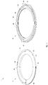
- the camera filter adaptor kit 1 includes a lens engagement apparatus 8 and a filter retaining apparatus 16.
- the lens engagement apparatus 8 is operable to engage a camera lens and be mounted thereto.
- the filter retaining apparatus 16 is operable to have a camera filter mounted onto it.
- the lens engagement apparatus 8 and the filter retaining apparatus 16 is further configured to interface with one another to form an engagement therebetween.
- the engagement may be a locking engagement. After forming the locking engagement, the lens engagement apparatus 8 and the filter retaining apparatus 16 can be further released from one another by manipulating one or both of the lens engagement apparatus 8 and the filter retaining apparatus 16.
- the filter retaining apparatus 16 includes a filter retaining portion 24 and an interfacing portion 32, which may be a first interfacing portion of the adaptor kit 1.
- the lens engagement apparatus 8 includes a lens coupling portion 40 and an interfacing portion 48, which may be a second interfacing portion of the adaptor kit 1.
- the filter retaining portion 24 corresponds to an upper portion of the filter retaining apparatus 16 and the first interfacing portion 32 corresponds to a lower portion of the filter retaining apparatus 16 located opposite the upper portion.
- the filter retaining apparatus 16 is a generally annular member
- the filter retaining portion 24 may form a first annular sub-member and the interfacing portion 32 may form a second annular sub-member.
- the filter retaining apparatus 16 and the filter retaining portion 24 may be integrally formed.
- the filter retaining portion 24 provides the retaining of a camera filter.
- the retaining of the camera filter defines a filter mount diameter 56 of the filter retaining portion 24.
- the camera filter is a circular filter having a circular rim supporting the filtering portion (ex: glass or similar material).
- the camera filter may have outer threads that screw onto inner threads 64 of the filter retaining portion 24, whereby a circumferential threaded engagement is formed and the camera filter is retained by the filter retaining portion 24. It will be appreciated that this threaded engagement is the same as a threaded engagement of a standard camera lens having inner threads that receive outer threads of a standard circular camera filter.
- the filter mount diameter 56 of the retaining portion 24 is the same as the diameter of the outer threads of the camera filter, which further defines a diameter of the camera filter.
- the filter retaining portion 24 further includes a circumferential rim 65 that extends upwardly from an upper surface 66 of the filter retaining portion 24.
- At least two engagement tabs 67 extend outwardly radially from the circumferential rim 65.
- the engagement tabs 67 are positioned opposite one another.
- the engagement tabs 67 may also each extend along an arc of the circumferential rim 65.
- the engagement tabs 67 define with the upper surface 66 of the filter retaining portion 24 a gap 68.
- a camera accessory such as a second camera filter or a lens hood may be attached to the filter retaining portion 24 via engagement with the engagement tabs 67.
- locking elements of the camera accessory may be received within the gap 68.
- the camera accessory may be attached in addition to attachment of the camera filter via the inner threads 64.
- the lens coupling portion 40 is configured for coupling to a front of a camera lens, whereby the lens engagement apparatus 8 becomes mounted to the camera lens.
- the coupling of the lens coupling portion 40 to the camera lens defines a lens coupling diameter 72 of the lens coupling portion 40.
- the camera lens may be circular may have inner threads located at a front portion thereof.
- the lens coupling portion 40 has lens engagement members 76 that engage the inner threads so as to be mounted to the camera lens.
- the lens coupling portion 40 has outer threads that screw onto the inner threads of the camera lens.
- the lens coupling portion 40 includes radially extending engagement tabs 76 that engage the inner threads of the camera lens.
- the lens coupling diameter 72 is defined by the engagement members of the lens coupling portion 40 and is the same as the diameter of the inner threads of the camera lens, which further defines a diameter of the camera lens.
- the first interfacing portion 32 of the filter retaining apparatus 16 and the second interfacing portion 48 of the lens engagement apparatus 8 cooperate to form the locking engagement of the filter retaining apparatus 16 with the lens engagement apparatus 8.
- the first interfacing portion 32 of the filter retaining apparatus 16 and the second interfacing portion 48 of the lens engagement apparatus 8 can be released from one another by an application of a force on one or both of the filter retaining apparatus 16 and the lens engagement apparatus 8.
- the force for releasing the apparatuses 8 and 16 may include a rotational (ex: twisting force).
- the locking engagement of the first interfacing portion 32 of the filter retaining apparatus 16 with the second interfacing portion 48 of the lens engagement apparatus 8 defines an interfacing diameter 80. More particularly, the interfacing diameter 80 is defined by parts of the first interfacing portion 32 that cooperate with parts of the second interfacing portion 48 to provide their mutual locking engagement.
- the second interfacing portion 48 is generally circular and includes a plurality of engagement tabs 88 extending radially outwardly.
- the engagement tabs 88 may be positioned diametrically opposite one another.
- the radially extending engagement tab 88 may be beveled.
- the first interfacing portion 32 of the filter retaining apparatus 16 has an inner sidewall 96 extending in an axial direction 104.
- One or more slots 112 are formed in the inner sidewall 96 and extend in an outward direction. The slots may be positioned diametrically opposite one another.
- the slots 112 are sized to receive the plurality of radially extending engagement tabs 88 of the second interfacing portion 48 of the lens engagement apparatus 8.
- the radially extending engagement tabs 88 being received within the slots 112 forms the locking engagement of the first interfacing portion 32 of the filter retaining apparatus 16 with the second interfacing portion 48 of the lens engagement apparatus 8.
- the radially extending engagement tabs 88 abut against an upper lip 120 of portions of the sidewall 96 that define the slots 112, which prevents separation of the lens engagement apparatus 8 and the filter retaining apparatus 16 from one another.
- the distance between oppositely positioned engagement tabs 88 of the second interfacing portion 48 which corresponds to the distance between oppositely position slots 112 of the first interfacing portion 32, defines the interfacing diameter 80.
- interfacing diameter 80 is defined from a circumferential engagement of the first interfacing portion 32 of the filter retaining apparatus 16 with the second interfacing portion 48 of the lens engagement apparatus 8 in the illustrated example, it will be understood that in other example embodiments the interfacing diameter 80 may be defined by a non-circumferential engagement thereof.
- the second interfacing portion 48 may be slightly oblong in that a first distance between the outer edges of oppositely positioned radially extending engagement tabs 88 is greater that a second distance between opposite outer edges of the second interfacing portion 48 that do not have the engagement tabs (such as portions offset by 90 degrees from the engagement tabs 88).
- a circumference defined by the inner sidewall 96 of the interfacing portion 32 of the filter retaining apparatus 16 may also be slightly oblong in that a third distance between opposite inner edges of inner sidewalls 96 that do not have slots 112 formed therein is greater than a fourth distance between the inner edges of the oppositely positioned slots 112. Furthermore, the distance between opposite inner edges of inner sidewalls 96 that do not have slots 112 formed therein may substantially correspond with the distance between the outer edges of oppositely positioned radially extending engagement tabs 88 of the second interfacing portion 48.
- the second interfacing portion 48 is received within the first interfacing portion 32 wherein the radially extending engagement tabs 88 (defining the first distance) are first aligned with opposite inner edges sidewalls 96 that do not have slots 112 formed therein (defining the third distance).
- This first alignment may be indicated by alignment of a first set of visual markings 128 on an underside of the first interfacing portion 32 with a second set of visual markings 136 on an upper side of the second interfacing portion 48.
- the first set of visual markings 128 may also correspond with protruding tabs 144 provided on the filter retaining apparatus 8 for facilitating manipulation.
- one or both of the lens filter retaining apparatus 16 and the lens engagement apparatus 8 is rotated so as to guide the radially extending engagement tabs 88 into the slots 112 to form the locking engagement, which corresponds to a second alignment of the first and second interfacing portions 32, 48.
- Application of a rotation in an opposite direction returns to the first alignment, whereby the first interfacing portion 32 and the second interfacing portion 48 may be disengaged from one another.
- a first set of magnetic elements 158 are angularly distributed about the first interfacing portion 32 and a second set of magnetic elements 160 are angularly distributed about the second interfacing portion 48.
- the first and second sets of magnetic elements 158, 160 are positioned so that they form a mutual magnetic coupling when the radially extending tabs 88 are receiving in the slots 112. This magnetic coupling may reduce accidental disengagement of the filter retaining apparatus 116 from the lens engagement apparatus 8. It will be appreciated that an angular force that is sufficient to overcome the magnetic attraction of the first and second sets of magnets 158 and 160 must be applied in order to rotate one or both of the filter retaining apparatus 16 and lens engagement apparatus 8 to the first alignment to disengage them from one another.
- additional magnetic elements may be angularly distributed on one or both of the first interfacing portion 32 and the second interfacing portion 48.
- the additional magnetic elements are positioned to provide magnetic coupling when the first alignment is formed, which provides tactile feedback to a user to indicate that one or both of the lens engagement apparatus 8 and filter retaining apparatus 16 are properly positioned to be rotated to form their mutual locking engagement.
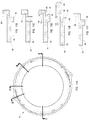
- the lens engagement apparatus 8 includes a first arc member 176 and a second arc member 184 pivotally attached to the first arc member 176. At least a first engagement member 76 is located on the first arc member 176 and at least a second engagement 76 is located on the second arc member 184.
- the first arc member 176 may be an annular member, as illustrated.
- the lens coupling portion 40 corresponds to an annular wall 192 extending axially from an upper portion of the lens engagement apparatus 8 that forms the second interfacing portion. As illustrated, a first portion of the annular wall 192 is provided on the first arc member 176 and a second portion of the annular wall 192 is provided on the second arc member 184.
- the first lens engagement member 76 extends radially from the portion of the annular wall 192 of the first arc member.
- the second les engagement member 76 extends radially from the portion of the annular wall 192 of the second arc member 184.
- the lens engagement apparatus 8 is in a coupling configuration when the second arc member 184 is pivoted to a position where it is substantially coplanar with the first arc member 176.
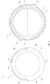
- Figures 1 to 5 illustrate the coupling configuration of the lens engagement apparatus 8. It will be appreciated that in the coupling configuration, and as best shown in Figures 4 and 5 , the first lens engagement member 76 located on the first arc member 176 is spaced apart from the second lens engagement member 76 located on the second arc member 184 by a distance corresponding to the lens coupling diameter 72.
- the lens engagement apparatus 8 is in a release configuration when the second arc member 184 is pivoted to a position where it forms a non-zero angle with the first arc member 176.
- Figures 6 to 8 illustrate the release configuration of the lens engagement apparatus 8. It will be appreciated that in the coupling configuration, and as best shown in Figure 8 , the first lens engagement member 76 located on the first arc member 176 is spaced apart from the second lens engagement member 76 located on the second arc member by a distance 196 that is less than the coupling diameter 72.
- the first arc member 176 has a thicker semi-circular portion 200 and a thinner semi-circular portion 208.
- An upper portion of the thicker semi-circular portion 200 forms the interfacing portion 48 of the lens engagement apparatus 8 and includes a radially extending engagement tab 88.
- a lower portion of the thicker semi-circular portion 200 includes part of the annular wall 192 and one of the engagement members 76.
- the thinner semi-circular portion 208 has another of the radially extending engagement tabs 88 and acts to define a boundary of the pivotal movement of the second arc member 184.
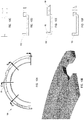
- the second arc member 184 ( Figures 10A to 10E ) is pivotally attached to posts 216 of the first arc member 176 formed at boundaries between the thicker semi-circular portion 200 and the thinner semi-circular portion 208.
- the range of pivotal motion of the second arc member 184 is limited at one boundary from abutting of the second arc member 184 against the thinner semi-circular portion 208 and is limited at the other boundary from the contacting of the annular wall 192 on each of the first arc member 176 and the second arc member 184.
- a lower portion of the second arc member 184 includes part of the annular wall 192 and another one of the engagement members 76.
- a portion of one of the radially extending engagement tabs 88 is formed in the second arc member 184.
- the lens engagement apparatus 8 is initially brought to its release configuration by pivoting the second arc member 184.
- the engagement members 76 are further positioned between a frontal wall of a camera lens.
- the second arc member 184 is further pivoted towards the coupling configuration of the lens engagement apparatus 8, wherein the distance 196 between the opposite engagement members 76 is increased, until the engagement members 76 contacts inner threads formed in the frontal wall of the camera lens. This causes the engagement members 76 to lockingly engage the camera lens.
- the inner threads of the camera lens are typically provided for mounting of a camera filter.
- the lens coupling diameter of the lens coupling portion 40 corresponds to the lens coupling diameter 72.
- the second arc member 184 is pivoted towards the release configuration, whereby the engagement members 76 are disengaged from the inner threads of the camera lens.
- a first notch 224 is formed on an outer edge of the first arc member 176 and a second notch 232 is formed on an outer edge of the second arc member 184, each notching providing accessing to the other arc member 184, 176.
- the first arc member 176 and second arc member 184 may be pushed away from another via the notches 224, 232 which causes pivoting of the second arc member 184 towards the release configuration.
- each engagement member 76 is a set of outer threads. Accordingly, the lens coupling portion 40 can be mounted onto a camera lens by screwing the engagement members 76 to the inner threads of the camera lens even when in the coupling configuration.
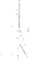
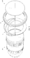
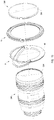
- the lens engagement apparatus 8 and the filter retaining apparatus 16 are in alignment with a camera lens 240 and camera filter 248.
- the camera filter 248 is mounted to the filter retaining portion 24 of the filter retaining apparatus 16 according to various examples described herein.
- the lens coupling portion 40 is mounted to the camera lens 240 according to various example embodiments described herein.
- the interfacing portion 32 of the first retaining apparatus 16 is lockingly engaged to the interfacing portion 48 of the lens engagement apparatus 8 according to various example embodiments described herein.
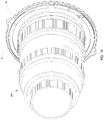
- the camera filter 248 is mounted to the camera lens 240 via the filter retaining apparatus 16 and the lens engagement apparatus 8.
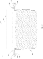
- Figure 17 illustrates a cross-sectional view in the direction F-F showing the filter retaining apparatus 16 and the lens engagement apparatus 8 having the camera filter 248 mounted thereto and being mounted to the camera lens 240.
- the lens engagement apparatus 8 is engaged to the camera lens 240 via engagement of engagement members 76 with inner threads of the camera lens 240.
- the camera filter 248 is mounted to the filter retaining apparatus 16 via engagement of outer threads of the camera filter 248 with inner threads 64 of the filter retaining apparatus 16. Locking engagement is formed between the filter retaining apparatus 16 and the lens engagement apparatus 8.
- the interfacing diameter 80 is greater than both the filter diameter 56 and the lens coupling diameter 72.
- the filter diameter 56 and the lens coupling diameter 72 are different (ex: the filter diameter 56 is greater than the lens coupling diameter 72).
- the interfacing diameter 80 defined by engagement of the first interfacing portion 32 of the filter retaining apparatus 16 with the second interfacing portion 48 of the lens engagement apparatus 8 is greater than the lens coupling diameter 72.
- a camera filter 248 having a filter diameter 256 that is different from the camera lens diameter 264 may be mounted via the camera filter adaptor kit 1.
- the filter retaining portion 24 of the filter retaining apparatus 16 may be configured to have a filter mount diameter 56 that corresponds to the interfacing diameter 80 or is less than the filter mount diameter 56. Accordingly, the filter mount diameter 56 may be less than the interfacing diameter 80.
- the filter mount diameter 56 may be greater than the lens coupling diameter 72.
- the difference in diameters allows interoperable use of a camera lens 240 of a given lens diameter 264 with a camera filter 248 of a given filter diameter 256 without requiring that the given lens diameter 264 match the given filter diameter 256 (where the given lens diameter 264 is equal to the given filter diameter 256) or requiring the use of specifically-sized adaptor that provides the specific matching between the lens diameter 264 with the given filter diameter 256 (where the given lens diameter 264 is different from given filter diameter 256). Where a camera filter 248 having a filter diameter 256 that is less than the lens diameter 264 of a camera lens 240 is used, some vignetting may be exhibited on images captured.
- a plurality of camera filters 248 having different filter diameters 256 may be used with a single camera lens 240 having a given lens diameter 264 by mounting to the camera lens 240 a lens engagement apparatus 8 having a lens coupling diameter 72 matching the lens diameter 264.
- each of the camera filters 248 are respectively mounted to a filter retaining apparatus 16 having a filter mount diameter 56 matching the filter diameter 256 of that camera filter 248 and an interfacing diameter that matches the interfacing diameter of the lens engagement apparatus 8.
- each of the lens engagement apparatus 8 and filter retaining apparatuses 16 have the same interfacing diameter 80. Accordingly, any one of the filters 248 may be used with the single camera lens 240 by selectively lockingly engaging the filter retaining portion 24 of one of the filters 248 to the lens engagement apparatus 8.
- a given single camera filter 248 having a given filter diameter 256 may be used with a plurality of camera lenses 240 having different lens diameters 264 by mounting the camera filter 248 onto a filter retaining apparatus 16 having a filter mount diameter 56 matching filter diameter 256.
- each of the camera lens 240 respectively has mounted onto it a lens engagement apparatus 8 having a lens coupling diameter 72 matching the lens diameter 264 of the camera lens 240 and an interfacing diameter that matches the interfacing diameter of the filter retaining apparatus 16.
- each of the lens engagement apparatuses 8 and the filter retaining apparatus 16 have the same interfacing diameter 80. Accordingly, the camera filter 248 may be used on any one of the camera lenses 240 by selectively lockingly engaging the filter retaining portion 32 to the lens engagement apparatus 8 mounted onto the camera lens 240 to be used.
- each of the camera lenses 240 is mounted with a lens engagement apparatus 8 that has a lens coupling diameter 72 matching the lens diameter 264 of that camera lens 240 and all the lens engagement apparatuses 8 have the same interfacing diameter.
- each of the camera filters 248 are mounted onto a filter retaining apparatus 16 that has a filter mount diameter 56 matching that camera filter 248 and all the filter retaining apparatuses 16 have the same interfacing diameter.
- the interfacing diameter of the filter retaining apparatuses 16 is the same as the interfacing diameter of the lens engagement apparatuses 8.
- any one of the filter retaining apparatuses 16 may be lockingly engaged to any one of the lens engagement apparatuses 8. Accordingly, any one of the camera filters 248 may be mounted onto any one of the camera lenses 240 via the locking engagement formed by their respective filter retaining apparatus 16 and lens engagement apparatus 8, despite the differences in their filter diameters 256 and lens diameters 264.
- the camera filter adaptor kit 1 described herein according to various example embodiments is a universal kit in that it allows use of camera filters across a range of different diameters 256 with camera lenses across a range of lens diameters 264.
- the interfacing diameter 80 is greater than the lens coupling diameter 72 by at least 5mm.
- the interfacing diameter 80 is greater than the lens coupling diameter 72 by at least 15mm.
- the interfacing diameter 80 is greater than the lens coupling diameter 72 by at least 10 percent of the lens coupling diameter 72.
- the interfacing diameter 80 is greater than the lens coupling diameter 72 by at least 25 percent of the lens coupling diameter 72.
- the interfacing diameter 80 is greater than the filter mount diameter 56 by at least 5 mm.
- the interfacing diameter 80 is greater than the filter mount diameter 56 by at least 15 mm.
- the interfacing diameter 80 is greater than the filter mount diameter 56 by at least 10 percent of the filter mount diameter 56.
- the interfacing diameter 80 is greater than the filter mount diameter 56 by at least 25 percent of the filter mount diameter 56.
- the filter mount diameter 56 is greater than the lens coupling diameter 72 by at least 5 mm.
- the filter mount diameter 56 is greater than the lens coupling diameter 72 by at least 15 mm.
- the filter mount diameter 56 is greater than the lens coupling diameter 72 by at least 10 percent of the lens coupling diameter 72.
- the filter mount diameter 56 is greater than the lens coupling diameter 72 by at least 25 percent of the lens coupling diameter 72.
- a camera filter adaptor kit 1 may be provided for consumer grade or professional grade camera lens and camera filters across a range of common camera diameters and filter diameters.
- Each of the lens engagement apparatus 8 and the filter retaining apparatus 16 have an interfacing diameter 80 of approximately 101 mm.
- the lens engagement apparatus 8 may have a lens coupling diameter 72 chosen from 49mm, 52mm, 55mm, 58mm, 60mm, 62mm, 67mm, 72mm, 77mm, 82mm, 86mm, and 95mm.
- the filter retaining apparatus 16 may have a filter mount diameter 56 chosen from 49mm, 52mm, 55mm, 58mm, 60mm, 62mm, 67mm, 72mm, 77mm, 82mm, 86mm, and 95mm.
- a camera lens having a lens diameter of any one of the common sizes listed above may be used with a filter of any one of the common sizes listed above.
- the interfacing diameter 80 is at least 5 mm greater than the largest diameter of filter and lens and over twice the size of the smallest diameter of filter and lens.
- a camera filter adaptor kit 1 may be provided for professional grade or specialty camera lens and camera filters across a range of common camera diameters and filter diameters.
- Each of the lens engagement apparatus 8 and the filter retaining apparatus 16 have an interfacing diameter 80 of approximately 150mm.
- the lens engagement apparatus 8 may have a lens coupling diameter 72 chosen from 67mm, 72mm, 77mm, 82mm, 86mm, 105mm, 107mm, 112mm, 122mm, 125mm, 127mm et 138mm.
- the filter retaining apparatus 16 may have a filter mount diameter 56 chosen from 67mm, 72mm, 77mm, 82mm, 86mm, 105mm, 107mm, 112mm, 122mm, 125mm, 127mm et 138mm.
- a camera filter adaptor kit 1 may be provided for consumer grade or recreational grade camera lenses and filters across a range of common diameters and filter diameters.
- Each of the lens engagement apparatus 8 and the filter retaining apparatus 16 have an interfacing diameter 80 of approximately 84mm.
- the lens engagement apparatus 8 may have a lens coupling diameter 37mm, 43mm, 46mm, 49mm, 52mm, 55mm, 58mm, 60mm, 62mm, 67mm, 72mm et 77mm.
- the filter retaining apparatus 16 may have a filter diameter 56 chosen from 37mm, 43mm, 46mm, 49mm, 52mm, 55mm, 58mm, 60mm, 62mm, 67mm, 72mm et 77mm.
- the camera filter adaptor kit 1 may include more than one lens engagement apparatus 8 and/or more than one filter retaining apparatus 16.
- the lens engagement apparatuses 8 and the filter retaining apparatus 16 all have the same interfacing diameter 80 but may have different filter mount diameters 56 and/or lens coupling diameters 72. Accordingly, the camera filter adaptor kit 1 is provided to be ready for use with multiple camera lenses 240 of different sizes and/or multiple camera filters 248 of the different sizes.
- a filter retaining apparatus 16 as described herein is provided and a lens engagement apparatus 8 as described herein is provided.
- the camera filter is mounted onto the filter retaining apparatus 16.
- the lens engagement apparatus 8 is mounted onto the camera lens.
- the filter retaining apparatus 16 is then lockingly engaged to the lens engagement apparatus 8 via the interfacing of their respective interfacing portions 32, 48.
- the filter retaining apparatus 16 is disengaged from the lens engagement apparatus 8 and another filter retaining apparatus 16 having the other filter to be used is lockingly engaged to the lens engagement apparatus 8 still mounted to the camera lens.
- the other filter may have a different filter diameter 256. It will be appreciated that the camera filter being used may be swapped without having to the change the component that is mounted to the lens. More particularly, the camera filter is changed while mounting of the lens engagement apparatus 8 to the camera lens 240 is maintained.
- various examples of the camera filter adaptor kit 1 allows reducing of the number of filters that need to be acquired or carried for a project.
- a single set of the different types of filters may be used for all of the lenses.
- various examples of the camera filter adaptor kit 1 facilitates swapping of camera filters during use.
- the user In a situation where the filter diameter must be matched to the lens diameter, the user must identify that the diameter of a selected filter matches the lens diameter of the camera lens.
- this identification is not required where all of the filter retaining apparatuses having interfacing diameters that matches the interfacing diameters of the lens engagement apparatuses.
- various examples of the camera filter adaptor kit 1 may simplify the task of swapping camera filters by having only to engage and disengage respective interfacing portions of the filter retaining apparatus and the lens engagement apparatus and without having dismount the lens engagement apparatus that is mounted onto the camera lens.
Landscapes
- Physics & Mathematics (AREA)
- General Physics & Mathematics (AREA)
- Optics & Photonics (AREA)
- Engineering & Computer Science (AREA)
- Multimedia (AREA)
- Signal Processing (AREA)
- Blocking Light For Cameras (AREA)
- Structure And Mechanism Of Cameras (AREA)
- Accessories Of Cameras (AREA)
- Studio Devices (AREA)
Claims (15)
- Kit (1) für einen Kamerafilteradapter, wobei das Kit Folgendes umfasst:eine erste Filterhaltevorrichtung (16), die einen Filterhalteabschnitt (24) und einen ersten Schnittstellenabschnitt (32) gegenüber dem Filterhalteabschnitt (24) besitzt, wobei der Filterhalteabschnitt (24) konfiguriert ist, einen ersten Kamerafilter (248) zu halten; undeine Objektiv-Verbindungsvorrichtung (8), die einen Objektivkopplungsabschnitt (40) und einen zweiten Schnittstellenabschnitt (48) gegenüber dem Objektivkopplungsabschnitt (40) besitzt, wobei der Objektivkopplungsabschnitt (40) konfiguriert ist, an ein Kameraobjektiv (240) gekoppelt zu werden, die Kopplung einen Objektivkopplungsdurchmesser (72) des Objektivkopplungsabschnitts (40) definiert und der zweite Schnittstellenabschnitt (48) als Schnittstelle zum ersten Schnittstellenabschnitt (32) der Filterhaltevorrichtung (16) konfiguriert ist, um eine Kopplung damit herzustellen, wobei die Schnittstelle einen Schnittstellendurchmesser (80) definiert, der größer als der Objektivkopplungsdurchmesser (72) ist, und der Objektiv-Verbindungsabschnitt (40) Folgendes umfasst:ein erstes Bogenelement (176), das mindestens ein erstes radial verlaufendes Verbindungselement (76) besitzt; undein zweites Bogenelement (184), das mindestens ein zweites radial verlaufendes Verbindungselement (76) besitzt, wobei das zweite Bogenelement (184) am ersten Bogenelement (176) drehbar angebracht ist; wobeiin einer Kopplungskonfiguration das erste Bogenelement (176) und das zweite Bogenelement (184) im Wesentlichen komplanar sind und das erste und das zweite radial verlaufende Element (76) einen ersten Abstand dazwischen definieren, der im Wesentlichen dem Objektivkopplungsdurchmesser (72) entspricht; undin einer Freigabekonfiguration das erste Bogenelement (176) quer zum zweiten Bogenelement (184) orientiert ist und das erste und das zweite radial verlaufende Element (76) einen zweiten Abstand (196) dazwischen definieren, der kleiner als der Objektivkopplungsdurchmesser (72) ist.
- Kit nach Anspruch 1, wobei der erste Schnittstellenabschnitt (32) eine lösbare arretierende Verbindung mit dem zweiten Schnittstellenabschnitt (48) bildet.
- Kit nach Anspruch 1 oder 2, wobei der Objektivkopplungsdurchmesser (72) durch einen Durchmesser (264) des Kameraobjektivs (248) definiert ist.
- Kit nach einem der Ansprüche 1 bis 3, wobei der Schnittstellendurchmesser (80) um mindestens 10 Prozent des Objektivkopplungsdurchmessers (76) größer als der Objektivkopplungsdurchmesser (76) ist.
- Kit nach einem der Ansprüche 1 bis 4, wobei die Halterung des Kameraobjektivs (248) einen Filterbefestigungsdurchmesser (56) des Filterhalteabschnitts (24) definiert und
der Schnittstellendurchmesser (80) größer als der Filterbefestigungsdurchmesser (56) ist. - Kit nach Anspruch 5, wobei der Schnittstellendurchmesser (80) um mindestens 10 Prozent des Filterbefestigungsdurchmessers (56) größer als der Filterbefestigungsdurchmesser (56) ist.
- Kit nach einem der Ansprüche 1 bis 6, wobei in der Kopplungskonfiguration das erste und das zweite radial verlaufende Verbindungselement (76) mit Innengewinden des Objektivs (240) verbunden sind, wodurch die Objektiv-Verbindungsvorrichtung (8) am Objektiv (240) arretiert wird; und
in der Freigabekonfiguration das erste und/oder das zweite radial verlaufende Verbindungselement (76) von den Innengewinden des Kameraobjektivs (240) gelöst sind. - Kit nach einem der Ansprüche 1 bis 7, wobei der zweite Schnittstellenabschnitt (48) der Objektiv-Verbindungsvorrichtung (8) mehrere radial verlaufende Verbindungslaschen (88) umfasst, die konfiguriert sind, mit dem ersten Schnittstellenabschnitt (32) der Filterhaltevorrichtung (16) zusammenzuwirken; und
der erste Schnittstellenabschnitt (24) der Filterhaltevorrichtung (16) eine ringförmige Wand (96) umfasst, die in einer Axialrichtung verläuft, wobei in der ringförmigen Wand (96) ein oder mehrere Schlitze (112) gebildet sind, um die mehreren Verbindungslaschen (88) des zweiten Schnittstellenabschnitts (48) der Objektiv-Verbindungsvorrichtung (8) aufzunehmen. - Kit nach einem der Ansprüche 1 bis 8, wobei der erste Schnittstellenabschnitt (32) der Filterhaltevorrichtung (16) einen ersten Satz in Winkelrichtung verteilter Magnetelemente (158) umfasst; wobei
der zweite Schnittstellenabschnitt (48) der Objektiv-Verbindungsvorrichtung (8) einen zweiten Satz in Winkelrichtung verteilter Magnetelemente (160) umfasst, der zum Verbinden mit dem ersten Satz Magnetelemente (158), wenn sich die Objektiv-Verbindungsvorrichtung (8) in der arretierten Verbindung mit der Filterhaltevorrichtung (16) befindet, konfiguriert ist. - Kit nach einem der Ansprüche 1 bis 9, wobei die Halterung des ersten Kamerafilters (248) einen ersten Filterbefestigungsdurchmesser (56) des Filterhalteabschnitts (24) der ersten Filterhaltevorrichtung (16) definiert; wobei
das Kit (1) ferner eine zweite Filterhaltevorrichtung umfasst, die einen Filterhalteabschnitt und einen Schnittstellenabschnitt gegenüber dem Filterhalteabschnitt besitzt, wobei der Filterhalteabschnitt konfiguriert ist, einen zweiten Kamerafilter zu halten, und die Halterung einen zweiten Filterbefestigungsdurchmesser des Filterhalteabschnitts der zweiten Filterhaltevorrichtung definiert;
der Schnittstellenabschnitt (48) der Objektiv-Verbindungsvorrichtung (8) als Schnittstelle wahlweise zum Schnittstellenabschnitt (48) der ersten Filterhaltevorrichtung (16) und zum Schnittstellenabschnitt der zweiten Filterhaltevorrichtung konfiguriert ist; und
der erste Filterbefestigungsdurchmesser (56) und der zweite Filterbefestigungsdurchmesser verschieden sind. - Objektiv-Verbindungsvorrichtung (8), die Folgendes umfasst:eine Objektiv-Verbindungsabschnitt (40), der konfiguriert ist, an ein Kameraobjektiv (240) gekoppelt zu werden, wobei die Kopplung einen Objektivkopplungsdurchmesser (72) definiert; undeinen Schnittstellenabschnitt (48) gegenüber dem Objektiv-Verbindungsabschnitt (40), wobei der Schnittstellenabschnitt (48) konfiguriert ist, eine Verbindung mit einer Filterhaltevorrichtung (16) zu bilden, um einen Kamerafilter (248) zu halten, die Verbindung einen Schnittstellendurchmesser (80) definiert, der größer als der Objektivkopplungsdurchmesser (72) ist, und der Objektiv-Verbindungsabschnitt (40) Folgendes umfasst:ein erstes Bogenelement (176), das mindestens ein erstes radial verlaufendes Verbindungselement (76) besitzt; undein zweites Bogenelement (184), das mindestens ein zweites radial verlaufendes Verbindungselement (76) besitzt, wobei das zweite Bogenelement (184) am ersten Bogenelement (176) drehbar angebracht ist; wobeiin einer Kopplungskonfiguration das erste Bogenelement (176) und das zweite Bogenelement (184) im Wesentlichen komplanar sind und das erste und das zweite radial verlaufende Element (76) einen ersten Abstand dazwischen definieren, der im Wesentlichen dem Objektivkopplungsdurchmesser (72) entspricht; undin einer Freigabekonfiguration das erste Bogenelement (176) quer zum zweiten Bogenelement (184) orientiert ist und das erste und das zweite radial verlaufende Element (76) einen zweiten Abstand (196) dazwischen definieren, der kleiner als der Objektivkopplungsdurchmesser (72) ist.
- Verfahren zum Verwenden einer Vorrichtung nach Anspruch 1 zum Befestigen eines Kamerafilters (248) an einem Kameraobjektiv (240), wobei das Verfahren Folgendes umfasst:Bereitstellen einer ersten Filterhaltevorrichtung (16), die einen Filterhalteabschnitt (24) und einen ersten Schnittstellenabschnitt (32) gegenüber dem Filterhalteabschnitt besitzt, wobei der Filterhalteabschnitt (24) konfiguriert ist, den Kamerafilter (248) zu halten;Bereitstellen einer Objektiv-Verbindungsvorrichtung (8), die einen Objektivkopplungsabschnitt (40) und einen zweiten Schnittstellenabschnitt (48) gegenüber dem Objektivkopplungsabschnitt (40) besitzt, wobei der Objektivkopplungsabschnitt (40) konfiguriert ist, an das Kameraobjektiv (240) gekoppelt zu werden, und der zweite Schnittstellenabschnitt (48) als Schnittstelle zum ersten Schnittstellenabschnitt (32) der Filterhaltevorrichtung (16) konfiguriert ist, um eine Verbindung damit herzustellen;Befestigen des Kamerafilters (248) an der ersten Filterhaltevorrichtung (24) durch Verbinden des Kamerafilters (248) mit dem Filterhalteabschnitt (24);Befestigen des Kameraobjektivs (240) an der Objektiv-Verbindungsvorrichtung (8) durch Verbinden des Kameraobjektivs (240) mit dem Objektivkopplungsabschnitt (40); undVerbinden der ersten Filterhaltevorrichtung (16) mit der Objektiv-Verbindungsvorrichtung (8) durch Verbinden des ersten Schnittstellenabschnitts (32) mit dem zweiten Schnittstellenabschnitt (48), wobei die Verbindung dazwischen einen Schnittstellendurchmesser (80) definiert, der größer als ein Objektivdurchmesser des Kameraobjektivs (240) ist.
- Verfahren nach Anspruch 12, wobei der Schnittstellendurchmesser (8) größer als ein Filterdurchmesser (256) des Kamerafilters (248) ist.
- Verfahren nach Anspruch 12 oder 13, das ferner Folgendes umfasst:Bereitstellen einer zweiten Filterhaltevorrichtung, die einen Filterhalteabschnitt und einen Schnittstellenabschnitt gegenüber ihrem Filterhalteabschnitt besitzt, wobei ihr Filterhalteabschnitt konfiguriert ist, einen zusätzlichen Kamerafilter zu halten;Befestigen des zusätzlichen Kamerafilters an der zweiten Filterhaltevorrichtung durch Verbinden des zusätzlichen Kamerafilters mit dem Filterhalteabschnitt der zweiten Filterhaltevorrichtung;Lösen des ersten Schnittstellenabschnitts (32) der ersten Filterhaltevorrichtung (16) vom zweiten Schnittstellenabschnitt (48) der Objektiv-Verbindungsvorrichtung (8), um die erste Filterhaltevorrichtung (16) von der Objektiv-Verbindungsvorrichtung (8) zu lösen; undarretierendes Verbinden der zweiten Filterhaltevorrichtung mit der Objektiv-Verbindungsvorrichtung (8) durch Verbinden des Filterhalteabschnitts der zweiten Filterhaltevorrichtung mit dem zweiten Schnittstellenabschnitt (48) der Objektiv-Verbindungsvorrichtung (8), wobei die arretierende Verbindung dazwischen einen zusätzlichen Schnittstellendurchmesser definiert, der gleich dem Schnittstellendurchmesser (80) ist, der durch das arretierende Verbinden der ersten Filterhaltevorrichtung (16) mit der Objektiv-Verbindungsvorrichtung (8) definiert ist; wobeider Filterdurchmesser des Kamerafilters vom Filterdurchmesser des zusätzlichen Kamerafilters verschieden ist.
- Verfahren nach Anspruch 14, wobei die Befestigung der Objektiv-Verbindungsvorrichtung (8) am Kameraobjektiv (240) während eines Lösens der ersten Filterhaltevorrichtung (16) und eines arretierenden Verbindens der zweiten Filterhaltevorrichtung aufrechterhalten wird.
Applications Claiming Priority (2)
| Application Number | Priority Date | Filing Date | Title |
|---|---|---|---|
| US201562387076P | 2015-12-23 | 2015-12-23 | |
| PCT/CA2016/051516 WO2017106968A1 (en) | 2015-12-23 | 2016-12-21 | Camera filter adaptor kit |
Publications (3)
| Publication Number | Publication Date |
|---|---|
| EP3394671A1 EP3394671A1 (de) | 2018-10-31 |
| EP3394671A4 EP3394671A4 (de) | 2019-07-10 |
| EP3394671B1 true EP3394671B1 (de) | 2020-09-30 |
Family
ID=59088762
Family Applications (1)
| Application Number | Title | Priority Date | Filing Date |
|---|---|---|---|
| EP16877046.9A Active EP3394671B1 (de) | 2015-12-23 | 2016-12-21 | Adapterkit für kamerafilter |
Country Status (5)
| Country | Link |
|---|---|
| US (1) | US10754116B2 (de) |
| EP (1) | EP3394671B1 (de) |
| JP (1) | JP6987777B2 (de) |
| CA (1) | CA3010107A1 (de) |
| WO (1) | WO2017106968A1 (de) |
Families Citing this family (8)
| Publication number | Priority date | Publication date | Assignee | Title |
|---|---|---|---|---|
| USD888804S1 (en) * | 2018-05-04 | 2020-06-30 | New Ideas Manufacturing LLC | Step-up ring |
| JP6989466B2 (ja) * | 2018-09-13 | 2022-01-05 | 株式会社東芝 | 光学フィルタ、撮像装置および測距装置 |
| USD983248S1 (en) * | 2021-08-06 | 2023-04-11 | New Ideas Manufacturing LLC | Camera lens filter |
| CN216595832U (zh) * | 2021-11-18 | 2022-05-24 | 蒙天培 | 具磁力装卸机制的镜具组件及其装卸工具与镜具组 |
| USD1050228S1 (en) * | 2022-08-29 | 2024-11-05 | Shenzhen Anymore Technology Limited | Toggle for photography filter |
| USD1055138S1 (en) * | 2022-08-29 | 2024-12-24 | Shenzhen Anymore Technology Limited | Filter for photography |
| USD986942S1 (en) * | 2022-11-14 | 2023-05-23 | Shenzhen Xingyingda Industry Co., Ltd. | Camera filter |
| USD1089365S1 (en) * | 2024-05-09 | 2025-08-19 | Shenzhen Neewer Technology Co. Ltd | Filter adapter |
Family Cites Families (14)
| Publication number | Priority date | Publication date | Assignee | Title |
|---|---|---|---|---|
| US2953970A (en) * | 1957-09-26 | 1960-09-27 | Indiana General Corp | Mount for optical system component |
| JPS5455829U (de) * | 1977-08-31 | 1979-04-18 | ||
| JPS57115027U (de) * | 1981-01-06 | 1982-07-16 | ||
| US4684231A (en) * | 1986-01-06 | 1987-08-04 | Athy Dale A | Camera filter adaptor system |
| US5040011A (en) * | 1990-10-17 | 1991-08-13 | Tiffen Manufacturing Corp. | Self-mounted camera accessories |
| US5208624A (en) * | 1991-10-10 | 1993-05-04 | Sony Corporation Of America | Camera lens and filter adapter assembly |
| US5528328A (en) * | 1995-02-21 | 1996-06-18 | O'farrill; Dave | Camera filter quick release adapter |
| JPH1090753A (ja) * | 1996-09-02 | 1998-04-10 | Shokin An | カメラにフィルタを装着する装置 |
| JP2007279149A (ja) * | 2006-04-03 | 2007-10-25 | Nikon Corp | 光学装置及び光学システム |
| US8238742B2 (en) | 2009-01-20 | 2012-08-07 | David Neiman | Apparatus and method for removably mounting filters to a photographic lens |
| US8014666B2 (en) * | 2009-01-20 | 2011-09-06 | David Neiman | Apparatus and method for removably mounting filters to a photographic lens |
| CN202583605U (zh) | 2012-04-17 | 2012-12-05 | 杭州跃诺科技有限公司 | 一种可调变减光镜 |
| US9042719B2 (en) * | 2012-11-20 | 2015-05-26 | Ye Xu | Magnetic lens filters and adapter assemblies for a camera |
| US10345680B2 (en) * | 2013-05-21 | 2019-07-09 | Forward Science Technologies, LLC | Optical filtering attachment |
-
2016
- 2016-12-21 CA CA3010107A patent/CA3010107A1/en active Pending
- 2016-12-21 JP JP2018552099A patent/JP6987777B2/ja not_active Expired - Fee Related
- 2016-12-21 EP EP16877046.9A patent/EP3394671B1/de active Active
- 2016-12-21 WO PCT/CA2016/051516 patent/WO2017106968A1/en not_active Ceased
- 2016-12-21 US US16/065,423 patent/US10754116B2/en not_active Expired - Fee Related
Non-Patent Citations (1)
| Title |
|---|
| None * |
Also Published As
| Publication number | Publication date |
|---|---|
| US10754116B2 (en) | 2020-08-25 |
| WO2017106968A1 (en) | 2017-06-29 |
| EP3394671A4 (de) | 2019-07-10 |
| CA3010107A1 (en) | 2017-06-29 |
| EP3394671A1 (de) | 2018-10-31 |
| JP2019502174A (ja) | 2019-01-24 |
| JP6987777B2 (ja) | 2022-01-05 |
| US20180372982A1 (en) | 2018-12-27 |
Similar Documents
| Publication | Publication Date | Title |
|---|---|---|
| EP3394671B1 (de) | Adapterkit für kamerafilter | |
| US9857666B2 (en) | Microscope observation tube smart-phone adaptor | |
| US5208624A (en) | Camera lens and filter adapter assembly | |
| JPH04301628A (ja) | ワンタッチ着脱式カメラアクセサリー | |
| US20130331148A1 (en) | Image Modifying Assembly for Smart Devices | |
| JP5573425B2 (ja) | ねじマウントレンズ鏡筒 | |
| MX2013010452A (es) | Lentes selectivamente acoplables y removibles para dispositivos de comunicacion. | |
| US20150212395A1 (en) | Imaging apparatus and imaging system | |
| CN103226230B (zh) | 具有快门柔性电路板的镜筒和具有该镜筒的摄像设备 | |
| WO2013131013A1 (en) | Optical scope couplers | |
| JP3370445B2 (ja) | マウント装置 | |
| US10712635B2 (en) | Interchangeable lens mount insert | |
| US20120250153A1 (en) | Two-lens device and stereoscopic imaging apparatus with two-lens device | |
| US20220146911A1 (en) | Filter mounting device for a camera | |
| JPWO2015114934A1 (ja) | カメラおよびアダプタ | |
| CN108513604A (zh) | 云台结构及具有该云台结构的云台、拍摄组件 | |
| AU2014225993B2 (en) | Translational optic alignment locking device | |
| WO2015153213A1 (en) | Variable neutral density filter system | |
| CN208888562U (zh) | 滤镜套架系统 | |
| CN208588890U (zh) | 一种镜头转接组件 | |
| TWM506977U (zh) | 能更換鏡片及調整鏡片角度之相機鏡具 | |
| CN1645180A (zh) | 变焦镜头装置 | |
| JP7466305B2 (ja) | アクセサリアダプタおよびレンズ鏡筒 | |
| US7866034B2 (en) | Triaxial connector release tool | |
| US20250008009A1 (en) | Smartphone optical device adapter |
Legal Events
| Date | Code | Title | Description |
|---|---|---|---|
| STAA | Information on the status of an ep patent application or granted ep patent |
Free format text: STATUS: THE INTERNATIONAL PUBLICATION HAS BEEN MADE |
|
| PUAI | Public reference made under article 153(3) epc to a published international application that has entered the european phase |
Free format text: ORIGINAL CODE: 0009012 |
|
| STAA | Information on the status of an ep patent application or granted ep patent |
Free format text: STATUS: REQUEST FOR EXAMINATION WAS MADE |
|
| 17P | Request for examination filed |
Effective date: 20180723 |
|
| AK | Designated contracting states |
Kind code of ref document: A1 Designated state(s): AL AT BE BG CH CY CZ DE DK EE ES FI FR GB GR HR HU IE IS IT LI LT LU LV MC MK MT NL NO PL PT RO RS SE SI SK SM TR |
|
| AX | Request for extension of the european patent |
Extension state: BA ME |
|
| DAV | Request for validation of the european patent (deleted) | ||
| DAX | Request for extension of the european patent (deleted) | ||
| A4 | Supplementary search report drawn up and despatched |
Effective date: 20190607 |
|
| RIC1 | Information provided on ipc code assigned before grant |
Ipc: G03B 11/00 20060101AFI20190603BHEP |
|
| GRAP | Despatch of communication of intention to grant a patent |
Free format text: ORIGINAL CODE: EPIDOSNIGR1 |
|
| STAA | Information on the status of an ep patent application or granted ep patent |
Free format text: STATUS: GRANT OF PATENT IS INTENDED |
|
| INTG | Intention to grant announced |
Effective date: 20200506 |
|
| GRAS | Grant fee paid |
Free format text: ORIGINAL CODE: EPIDOSNIGR3 |
|
| GRAA | (expected) grant |
Free format text: ORIGINAL CODE: 0009210 |
|
| STAA | Information on the status of an ep patent application or granted ep patent |
Free format text: STATUS: THE PATENT HAS BEEN GRANTED |
|
| AK | Designated contracting states |
Kind code of ref document: B1 Designated state(s): AL AT BE BG CH CY CZ DE DK EE ES FI FR GB GR HR HU IE IS IT LI LT LU LV MC MK MT NL NO PL PT RO RS SE SI SK SM TR |
|
| REG | Reference to a national code |
Ref country code: GB Ref legal event code: FG4D Ref country code: CH Ref legal event code: EP |
|
| REG | Reference to a national code |
Ref country code: AT Ref legal event code: REF Ref document number: 1319421 Country of ref document: AT Kind code of ref document: T Effective date: 20201015 Ref country code: DE Ref legal event code: R096 Ref document number: 602016045198 Country of ref document: DE |
|
| REG | Reference to a national code |
Ref country code: IE Ref legal event code: FG4D |
|
| PG25 | Lapsed in a contracting state [announced via postgrant information from national office to epo] |
Ref country code: SE Free format text: LAPSE BECAUSE OF FAILURE TO SUBMIT A TRANSLATION OF THE DESCRIPTION OR TO PAY THE FEE WITHIN THE PRESCRIBED TIME-LIMIT Effective date: 20200930 Ref country code: NO Free format text: LAPSE BECAUSE OF FAILURE TO SUBMIT A TRANSLATION OF THE DESCRIPTION OR TO PAY THE FEE WITHIN THE PRESCRIBED TIME-LIMIT Effective date: 20201230 Ref country code: GR Free format text: LAPSE BECAUSE OF FAILURE TO SUBMIT A TRANSLATION OF THE DESCRIPTION OR TO PAY THE FEE WITHIN THE PRESCRIBED TIME-LIMIT Effective date: 20201231 Ref country code: BG Free format text: LAPSE BECAUSE OF FAILURE TO SUBMIT A TRANSLATION OF THE DESCRIPTION OR TO PAY THE FEE WITHIN THE PRESCRIBED TIME-LIMIT Effective date: 20201230 Ref country code: HR Free format text: LAPSE BECAUSE OF FAILURE TO SUBMIT A TRANSLATION OF THE DESCRIPTION OR TO PAY THE FEE WITHIN THE PRESCRIBED TIME-LIMIT Effective date: 20200930 Ref country code: FI Free format text: LAPSE BECAUSE OF FAILURE TO SUBMIT A TRANSLATION OF THE DESCRIPTION OR TO PAY THE FEE WITHIN THE PRESCRIBED TIME-LIMIT Effective date: 20200930 |
|
| REG | Reference to a national code |
Ref country code: AT Ref legal event code: MK05 Ref document number: 1319421 Country of ref document: AT Kind code of ref document: T Effective date: 20200930 |
|
| PG25 | Lapsed in a contracting state [announced via postgrant information from national office to epo] |
Ref country code: RS Free format text: LAPSE BECAUSE OF FAILURE TO SUBMIT A TRANSLATION OF THE DESCRIPTION OR TO PAY THE FEE WITHIN THE PRESCRIBED TIME-LIMIT Effective date: 20200930 Ref country code: LV Free format text: LAPSE BECAUSE OF FAILURE TO SUBMIT A TRANSLATION OF THE DESCRIPTION OR TO PAY THE FEE WITHIN THE PRESCRIBED TIME-LIMIT Effective date: 20200930 |
|
| REG | Reference to a national code |
Ref country code: NL Ref legal event code: MP Effective date: 20200930 |
|
| REG | Reference to a national code |
Ref country code: LT Ref legal event code: MG4D |
|
| PG25 | Lapsed in a contracting state [announced via postgrant information from national office to epo] |
Ref country code: SM Free format text: LAPSE BECAUSE OF FAILURE TO SUBMIT A TRANSLATION OF THE DESCRIPTION OR TO PAY THE FEE WITHIN THE PRESCRIBED TIME-LIMIT Effective date: 20200930 Ref country code: EE Free format text: LAPSE BECAUSE OF FAILURE TO SUBMIT A TRANSLATION OF THE DESCRIPTION OR TO PAY THE FEE WITHIN THE PRESCRIBED TIME-LIMIT Effective date: 20200930 Ref country code: CZ Free format text: LAPSE BECAUSE OF FAILURE TO SUBMIT A TRANSLATION OF THE DESCRIPTION OR TO PAY THE FEE WITHIN THE PRESCRIBED TIME-LIMIT Effective date: 20200930 Ref country code: PT Free format text: LAPSE BECAUSE OF FAILURE TO SUBMIT A TRANSLATION OF THE DESCRIPTION OR TO PAY THE FEE WITHIN THE PRESCRIBED TIME-LIMIT Effective date: 20210201 Ref country code: RO Free format text: LAPSE BECAUSE OF FAILURE TO SUBMIT A TRANSLATION OF THE DESCRIPTION OR TO PAY THE FEE WITHIN THE PRESCRIBED TIME-LIMIT Effective date: 20200930 Ref country code: LT Free format text: LAPSE BECAUSE OF FAILURE TO SUBMIT A TRANSLATION OF THE DESCRIPTION OR TO PAY THE FEE WITHIN THE PRESCRIBED TIME-LIMIT Effective date: 20200930 |
|
| PG25 | Lapsed in a contracting state [announced via postgrant information from national office to epo] |
Ref country code: ES Free format text: LAPSE BECAUSE OF FAILURE TO SUBMIT A TRANSLATION OF THE DESCRIPTION OR TO PAY THE FEE WITHIN THE PRESCRIBED TIME-LIMIT Effective date: 20200930 Ref country code: AT Free format text: LAPSE BECAUSE OF FAILURE TO SUBMIT A TRANSLATION OF THE DESCRIPTION OR TO PAY THE FEE WITHIN THE PRESCRIBED TIME-LIMIT Effective date: 20200930 Ref country code: AL Free format text: LAPSE BECAUSE OF FAILURE TO SUBMIT A TRANSLATION OF THE DESCRIPTION OR TO PAY THE FEE WITHIN THE PRESCRIBED TIME-LIMIT Effective date: 20200930 Ref country code: IS Free format text: LAPSE BECAUSE OF FAILURE TO SUBMIT A TRANSLATION OF THE DESCRIPTION OR TO PAY THE FEE WITHIN THE PRESCRIBED TIME-LIMIT Effective date: 20210130 Ref country code: PL Free format text: LAPSE BECAUSE OF FAILURE TO SUBMIT A TRANSLATION OF THE DESCRIPTION OR TO PAY THE FEE WITHIN THE PRESCRIBED TIME-LIMIT Effective date: 20200930 |
|
| PG25 | Lapsed in a contracting state [announced via postgrant information from national office to epo] |
Ref country code: NL Free format text: LAPSE BECAUSE OF FAILURE TO SUBMIT A TRANSLATION OF THE DESCRIPTION OR TO PAY THE FEE WITHIN THE PRESCRIBED TIME-LIMIT Effective date: 20200930 Ref country code: SK Free format text: LAPSE BECAUSE OF FAILURE TO SUBMIT A TRANSLATION OF THE DESCRIPTION OR TO PAY THE FEE WITHIN THE PRESCRIBED TIME-LIMIT Effective date: 20200930 |
|
| REG | Reference to a national code |
Ref country code: DE Ref legal event code: R097 Ref document number: 602016045198 Country of ref document: DE |
|
| REG | Reference to a national code |
Ref country code: CH Ref legal event code: PL |
|
| PLBE | No opposition filed within time limit |
Free format text: ORIGINAL CODE: 0009261 |
|
| STAA | Information on the status of an ep patent application or granted ep patent |
Free format text: STATUS: NO OPPOSITION FILED WITHIN TIME LIMIT |
|
| PG25 | Lapsed in a contracting state [announced via postgrant information from national office to epo] |
Ref country code: MC Free format text: LAPSE BECAUSE OF FAILURE TO SUBMIT A TRANSLATION OF THE DESCRIPTION OR TO PAY THE FEE WITHIN THE PRESCRIBED TIME-LIMIT Effective date: 20200930 Ref country code: DK Free format text: LAPSE BECAUSE OF FAILURE TO SUBMIT A TRANSLATION OF THE DESCRIPTION OR TO PAY THE FEE WITHIN THE PRESCRIBED TIME-LIMIT Effective date: 20200930 |
|
| REG | Reference to a national code |
Ref country code: BE Ref legal event code: MM Effective date: 20201231 |
|
| 26N | No opposition filed |
Effective date: 20210701 |
|
| PG25 | Lapsed in a contracting state [announced via postgrant information from national office to epo] |
Ref country code: IE Free format text: LAPSE BECAUSE OF NON-PAYMENT OF DUE FEES Effective date: 20201221 Ref country code: IT Free format text: LAPSE BECAUSE OF FAILURE TO SUBMIT A TRANSLATION OF THE DESCRIPTION OR TO PAY THE FEE WITHIN THE PRESCRIBED TIME-LIMIT Effective date: 20200930 Ref country code: LU Free format text: LAPSE BECAUSE OF NON-PAYMENT OF DUE FEES Effective date: 20201221 |
|
| PG25 | Lapsed in a contracting state [announced via postgrant information from national office to epo] |
Ref country code: SI Free format text: LAPSE BECAUSE OF FAILURE TO SUBMIT A TRANSLATION OF THE DESCRIPTION OR TO PAY THE FEE WITHIN THE PRESCRIBED TIME-LIMIT Effective date: 20200930 Ref country code: CH Free format text: LAPSE BECAUSE OF NON-PAYMENT OF DUE FEES Effective date: 20201231 Ref country code: LI Free format text: LAPSE BECAUSE OF NON-PAYMENT OF DUE FEES Effective date: 20201231 |
|
| PG25 | Lapsed in a contracting state [announced via postgrant information from national office to epo] |
Ref country code: IS Free format text: LAPSE BECAUSE OF FAILURE TO SUBMIT A TRANSLATION OF THE DESCRIPTION OR TO PAY THE FEE WITHIN THE PRESCRIBED TIME-LIMIT Effective date: 20210130 Ref country code: TR Free format text: LAPSE BECAUSE OF FAILURE TO SUBMIT A TRANSLATION OF THE DESCRIPTION OR TO PAY THE FEE WITHIN THE PRESCRIBED TIME-LIMIT Effective date: 20200930 Ref country code: MT Free format text: LAPSE BECAUSE OF FAILURE TO SUBMIT A TRANSLATION OF THE DESCRIPTION OR TO PAY THE FEE WITHIN THE PRESCRIBED TIME-LIMIT Effective date: 20200930 Ref country code: CY Free format text: LAPSE BECAUSE OF FAILURE TO SUBMIT A TRANSLATION OF THE DESCRIPTION OR TO PAY THE FEE WITHIN THE PRESCRIBED TIME-LIMIT Effective date: 20200930 |
|
| PG25 | Lapsed in a contracting state [announced via postgrant information from national office to epo] |
Ref country code: MK Free format text: LAPSE BECAUSE OF FAILURE TO SUBMIT A TRANSLATION OF THE DESCRIPTION OR TO PAY THE FEE WITHIN THE PRESCRIBED TIME-LIMIT Effective date: 20200930 |
|
| PG25 | Lapsed in a contracting state [announced via postgrant information from national office to epo] |
Ref country code: BE Free format text: LAPSE BECAUSE OF NON-PAYMENT OF DUE FEES Effective date: 20201231 |
|
| PGFP | Annual fee paid to national office [announced via postgrant information from national office to epo] |
Ref country code: GB Payment date: 20231222 Year of fee payment: 8 |
|
| PGFP | Annual fee paid to national office [announced via postgrant information from national office to epo] |
Ref country code: FR Payment date: 20231222 Year of fee payment: 8 Ref country code: DE Payment date: 20231222 Year of fee payment: 8 |
|
| REG | Reference to a national code |
Ref country code: DE Ref legal event code: R119 Ref document number: 602016045198 Country of ref document: DE |
|
| GBPC | Gb: european patent ceased through non-payment of renewal fee |
Effective date: 20241221 |
|
| PG25 | Lapsed in a contracting state [announced via postgrant information from national office to epo] |
Ref country code: DE Free format text: LAPSE BECAUSE OF NON-PAYMENT OF DUE FEES Effective date: 20250701 |
|
| PG25 | Lapsed in a contracting state [announced via postgrant information from national office to epo] |
Ref country code: GB Free format text: LAPSE BECAUSE OF NON-PAYMENT OF DUE FEES Effective date: 20241221 |
|
| PG25 | Lapsed in a contracting state [announced via postgrant information from national office to epo] |
Ref country code: FR Free format text: LAPSE BECAUSE OF NON-PAYMENT OF DUE FEES Effective date: 20241231 |