EP3394840B1 - Distributeur automatique de monnaie - Google Patents
Distributeur automatique de monnaie Download PDFInfo
- Publication number
- EP3394840B1 EP3394840B1 EP16779095.5A EP16779095A EP3394840B1 EP 3394840 B1 EP3394840 B1 EP 3394840B1 EP 16779095 A EP16779095 A EP 16779095A EP 3394840 B1 EP3394840 B1 EP 3394840B1
- Authority
- EP
- European Patent Office
- Prior art keywords
- storage device
- docking station
- teller machine
- automated teller
- machine according
- Prior art date
- Legal status (The legal status is an assumption and is not a legal conclusion. Google has not performed a legal analysis and makes no representation as to the accuracy of the status listed.)
- Active
Links
Images






Classifications
-
- G—PHYSICS
- G07—CHECKING-DEVICES
- G07F—COIN-FREED OR LIKE APPARATUS
- G07F19/00—Complete banking systems; Coded card-freed arrangements adapted for dispensing or receiving monies or the like and posting such transactions to existing accounts, e.g. automatic teller machines
- G07F19/20—Automatic teller machines [ATMs]
- G07F19/203—Dispensing operations within ATMs
-
- F—MECHANICAL ENGINEERING; LIGHTING; HEATING; WEAPONS; BLASTING
- F16—ENGINEERING ELEMENTS AND UNITS; GENERAL MEASURES FOR PRODUCING AND MAINTAINING EFFECTIVE FUNCTIONING OF MACHINES OR INSTALLATIONS; THERMAL INSULATION IN GENERAL
- F16B—DEVICES FOR FASTENING OR SECURING CONSTRUCTIONAL ELEMENTS OR MACHINE PARTS TOGETHER, e.g. NAILS, BOLTS, CIRCLIPS, CLAMPS, CLIPS OR WEDGES; JOINTS OR JOINTING
- F16B21/00—Means for preventing relative axial movement of a pin, spigot, shaft or the like and a member surrounding it; Stud-and-socket releasable fastenings
- F16B21/09—Releasable fastening devices with a stud engaging a keyhole slot
-
- G—PHYSICS
- G07—CHECKING-DEVICES
- G07D—HANDLING OF COINS OR VALUABLE PAPERS, e.g. TESTING, SORTING BY DENOMINATIONS, COUNTING, DISPENSING, CHANGING OR DEPOSITING
- G07D1/00—Coin dispensers
-
- G—PHYSICS
- G07—CHECKING-DEVICES
- G07D—HANDLING OF COINS OR VALUABLE PAPERS, e.g. TESTING, SORTING BY DENOMINATIONS, COUNTING, DISPENSING, CHANGING OR DEPOSITING
- G07D11/00—Devices accepting coins; Devices accepting, dispensing, sorting or counting valuable papers
- G07D11/40—Device architecture, e.g. modular construction
-
- G—PHYSICS
- G07—CHECKING-DEVICES
- G07F—COIN-FREED OR LIKE APPARATUS
- G07F19/00—Complete banking systems; Coded card-freed arrangements adapted for dispensing or receiving monies or the like and posting such transactions to existing accounts, e.g. automatic teller machines
- G07F19/20—Automatic teller machines [ATMs]
- G07F19/205—Housing aspects of ATMs
-
- G—PHYSICS
- G07—CHECKING-DEVICES
- G07F—COIN-FREED OR LIKE APPARATUS
- G07F9/00—Details other than those peculiar to special kinds or types of apparatus
- G07F9/06—Coin boxes
-
- F—MECHANICAL ENGINEERING; LIGHTING; HEATING; WEAPONS; BLASTING
- F16—ENGINEERING ELEMENTS AND UNITS; GENERAL MEASURES FOR PRODUCING AND MAINTAINING EFFECTIVE FUNCTIONING OF MACHINES OR INSTALLATIONS; THERMAL INSULATION IN GENERAL
- F16B—DEVICES FOR FASTENING OR SECURING CONSTRUCTIONAL ELEMENTS OR MACHINE PARTS TOGETHER, e.g. NAILS, BOLTS, CIRCLIPS, CLAMPS, CLIPS OR WEDGES; JOINTS OR JOINTING
- F16B2/00—Friction-grip releasable fastenings
- F16B2/02—Clamps, i.e. with gripping action effected by positive means other than the inherent resistance to deformation of the material of the fastening
- F16B2/18—Clamps, i.e. with gripping action effected by positive means other than the inherent resistance to deformation of the material of the fastening using cams, levers, eccentrics, or toggles
- F16B2/185—Clamps, i.e. with gripping action effected by positive means other than the inherent resistance to deformation of the material of the fastening using cams, levers, eccentrics, or toggles using levers
Definitions
- the invention relates to an ATM for paying out cash to a customer.
- An ATM is a technical device for self-service cash withdrawals at financial and credit institutions.
- automatic teller machines are designed with a payout module which is set up to pay out an amount of money requested by a customer in the form of banknotes to the latter.
- Known additional modules mostly include several docking stations, which are permanently provided in a corresponding ATM.
- a storage device for storing coins can be detachably fastened to each of the docking stations.
- Such storage devices are also referred to as coin hoppers.
- a plurality of storage devices within an automated teller machine usually hold coins of different denominations, so that the exact payout amount requested by the customer can be formed by combining different coins.
- a respective docking station with a mechanism equipped, which allows a respectively assigned storage device to be pivoted from its vertical position into an inclined position and then to be detached from the docking station.
- the refilled storage device is brought into the inclined position, then hooked into the mechanism of the docking station and then swiveled back into the vertical position.
- the pivoting of the storage device relative to the docking station means that the docking station cannot be placed up to a stop against a rear wall in the automated teller machine. Rather, a distance to the rear wall must remain. Sufficient space must also be provided above each storage device in order to be able to carry out the pivoting movement. Finally, tilting a corresponding storage device can cause coins to fall out of it.
- U.S. 5,873,446 discloses a coin storage device. This comprises a housing in which a coin drawer is held in a removable manner. Furthermore, a locking device is provided, which is set up to block the removal of the coin drawer.
- the storage device Due to the exclusively linear relative movement, there is no tilting of the storage device. Accordingly, the storage device can be positioned immediately adjacent to a rear wall of the ATM. Furthermore, no space is required above the storage device for attaching the storage device to the docking station. Finally, due to the exclusively linear relative movement, there is no risk of coins falling out of the storage device.
- the docking station can be in the form of a pedestal. Furthermore, the docking station can be made partially or entirely of sheet metal.
- the storage device can have a receptacle, in particular a funnel, for storing the coins. Furthermore, the storage device can include a counting device for counting the coins.
- the engagement of the first and second guide device includes in particular a form fit in the positive (upward) and negative (downward) vertical direction. Accordingly, the storage device can only be displaced relative to the docking station in the horizontal direction.
- the first or second guide device can be, for example, rails, profile parts, slots, grooves, in particular T-grooves, or another receiving element.
- the other of the first and second guide element is designed as a corresponding engagement element, in particular a rail, a profile part, a welt, a link, a pin or the like, which interacts with the receiving element in a form-fitting manner in order to bring about the exclusively linear guidance.
- the ATM can also be referred to as a cash machine, ATM or cash dispenser.
- the ATM has a jack and a plug.
- the plug is designed to be plugged into the socket to establish an electrical connection, with the plug being plugged into the socket by the exclusively linear movement of the storage device relative to the docking station.
- the electrical connection is thus advantageously created simply by moving the storage device relative to the docking station.
- an excessively long cable is installed, which allows the storage device to first be connected to the cable and then attached to the docking station.
- Such a prior art cable disadvantageously takes up space.
- it can impede the movement of the storage device relative to the docking station or even damage itself.
- no further manipulations are required in order to electrically connect the socket and the plug to one another.
- an electrical device in particular a counting device for counting the coins to be dispensed, of the storage device can be electrically connected to a control module of the automated teller machine.
- the automated teller machine includes a back panel.
- the backplane has one of the plug and socket and the stocker has the other of the plug and socket.
- the back panel may be a back panel of a coin drawer of the ATM.
- the other of the plug and socket may also be provided on a rear wall of the stocker.
- the ATM also includes a locking device. This is set up to lock the storage device to the docking station in an end position at one end of the exclusively linear movement. That is, in a first step, the storage device and the docking station being engaged with each other using the first and second guide means. This intervention ensures that the storage device is guided so that it can move relative to the docking station in an exclusively linear manner. At one end of the exclusively linear movement, the storage device reaches the end position. In this position, the storage device is finally fixed relative to the docking station with the aid of the locking device by locking it (locked position of the locking device).
- the locking device is unlocked (unlocked position of the locking device), the storage device is moved back exclusively linearly from its end position and then removed from its engagement with the docking station, with the first and second guide devices being disengaged from one another.
- a defined position of the storage device relative to the docking station can thus advantageously be ensured with the aid of the locking device.
- the locking device is set up to move the storage device into the end position and to lock it there with the docking station, with the plug preferably being plugged into the socket in the end position.
- the relative position of the plug and socket in the end position can be precisely controlled, which can improve their service life on the one hand and good electrical contact between them on the other.
- the locking device has an over-center mechanism.
- the over-centre mechanism ensures that the locking device tends to remain in its locked position. This advantageously avoids unintentional, ie automatic, unlocking of the locking device.
- the locking device together with the over dead center mechanism can be designed in such a way that when the over dead center is exceeded, the operator is given haptic feedback that the over dead center has been exceeded. In particular, this haptic Feedback generated by a sudden reduction in the actuating force required to move the locking device to its locked position. At the same time, the force required for unlocking suddenly increases when the locking device is actuated to unlock it.
- the locking device has a link and a corresponding link element.
- the link element can be displaced in the link for locking the storage device with the docking station and/or for moving the storage device into the end position.
- the link can be designed as a slot or groove.
- the connecting link can have a first and a second section, the first and second section being oriented at an angle to one another.
- the first section preferably extends in the direction of the exclusively linear movement of the storage device relative to the docking station, the second section preferably at an angle, in particular perpendicularly thereto.
- the link element can be designed, for example, as a sliding block or pin.
- the connecting link is formed on a base plate of the storage device.
- a lever pivotably mounted on the docking station encompasses the link element.
- the lever for locking the storage device to the docking station can be pivoted. With the help of the lever, actuation of the locking device can be made easily accessible for the operator.
- a handle part of the lever can be arranged in front of a front wall of the storage device when it is in its end position.
- the lever ratios can advantageously be selected in such a way that - with an average actuating force to be expected - the corresponding reaction forces, e.g. the releasing force for removing the plug from the socket and frictional forces between the link and the link element, are overcome , but without accelerating the storage device too much. This ensures jerk-free release as well as favorable dynamics, as a result of which the risk of the coins falling out of the storage device is reduced even further.
- the lever forms the over-center mechanism together with a slot in a cover element, in particular a cover plate, of the docking station.
- the slot can have a curved profile.
- the locking device has a latch and a corresponding counter-latch.
- the latch can be brought into engagement with the counter-latch for locking the storage device to the docking station.
- the engagement preferably takes place in a direction perpendicular to the direction along which the exclusively linear movement of the storage device relative to the docking station takes place.
- the catch can be designed as a hook, for example, and the counter catch as an opening, in particular as a passage or pocket.
- the docking station has one of the latch and the counter-latch and the storage device has the other of the latch and the counter-latch.
- the counter-lock preferably comes into engagement with the lock by driving over it. More preferably, the overrunning takes place by the exclusively linear movement of the storage device relative to the docking station. This advantageously results in an automatic engagement of the latch and counter-latch.
- Self-acting means that no external energy is required to bring the latch and counter-latch into engagement with each other. In particular, the engagement takes place with the aid of spring-elastic forces.
- the engagement of the catch and the counter catch preferably takes place in the end position of the storage device relative to the docking station, that is to say at a desired end of the exclusively linear movement. As a result, the storage device can be easily attached to the docking station.
- the catch is formed on a lever attached to the docking station.
- the counter-lock is preferably provided on a base plate of the storage device. More preferably, the lever for engaging the latch and the counter-latch is bendable.
- the lever is preferably designed in whole or in part as a leaf spring. More preferably, it is attached at one end to the docking station, for example screwed or riveted. The other end of the lever is preferably free, so it can be actuated, in particular bent, by an operator in order to thereby move a catch arranged in particular on an upper side of the lever.
- the movement of the detent preferably takes place on a circular line up (for locking) and down (for unlocking). "Up” and “down” here refer to the direction of gravity.
- the catch is designed as a sheet metal hook bent out and/or the counter catch is designed as an opening. Both the metal hook and the opening are easy to make.
- the automated teller machine includes slots and tenons.
- the pins are designed to engage in one of the slots and/or to engage behind an edge area delimiting a respective slot over at least part of the exclusively linear movement of the storage device relative to the docking station.
- the first guide means includes one of the slots and the tenons and the second guide means the other of the slots and the tenons.
- the slots can have a keyhole shape with an opening and an in have this opening channel.
- the pins can in particular each have a mushroom shape. The corresponding mushroom head can be inserted through the opening of the slot in a vertical direction. A shaft of the mushroom can then be inserted into the channel in a horizontal direction, which corresponds to the exclusively linear movement of the storage device relative to the docking station. The mushroom head engages behind the edge area of the docking station that delimits the respective channel.
- the automated teller machine includes hooks and a panel body.
- the plate body is guided between the hooks.
- the hooks can engage behind the plate body over at least part of the exclusively linear movement of the storage device relative to the docking station.
- the first guide means comprises one of the hooks and the plate body
- the second guide means comprises the other of the hooks and the plate body.
- the hooks can in particular be designed as hooks which grip the plate body at least in the end position of the storage device relative to the docking station.
- the hooks may be otherwise attached as bent out of a deck member of the docking station or welded thereto.
- the storage device has a receptacle for the coins and a base plate.
- the base plate is attached to the receiving container, in particular in a detachable manner.
- the docking station can preferably include a cover element, in particular a cover plate, on which the storage device, in particular its base plate, is mounted so that it can slide relative to the docking station for the exclusively linear movement of the storage device.
- the base plate can be clipped onto the receptacle.
- the use of a base plate has the advantage that standard receptacles can be used and modified for the application desired at hand. Making the docking station out of sheet metal results in a simple manufacturing process.
- the bottom panel has one of the first and second guide means and the cover member has the other of the first and second guide means.
- the automated teller machine includes a machine body and a coin drawer.
- the coin drawer is slidably movable into and out of the machine housing.
- the coin drawer preferably has the docking station.
- the coin drawer advantageously comprises a number of docking stations, each of which is assigned a storage device. By allowing the coin drawer to be moved out of the machine body, only a small opening in the machine body is required to allow an operator to access the one or more docking stations and associated storage devices.
- a service machine for paying out cash to a customer, with a docking station, which has a first guide device, and a storage device for storing coins, which has a second guide device, the first and second guide devices being set up to communicate with one another to be brought into engagement in such a way that the storage device is guided exclusively linearly movably relative to the docking station.
- a service machine is understood to mean, in particular, vending and bank machines.
- the service machine can be an ATM, a ticket machine, a vending machine, an account information terminal, a lottery terminal, a parcel machine for sending or receiving (postal) parcels, or a check-in terminal.
- the features described here for the ATM apply accordingly to the service machine.
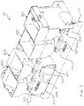
- FIG. 1 shows a perspective view of an automated teller machine 1 according to an embodiment. Instead of the ATM 1, it could also be any other service machine.
- the automatic teller machine 1 comprises a machine housing 10.
- the machine housing 10 can, for example, have a cylindrical shape with a rectangular base area.
- the ATM also includes a coin drawer 30, which is also shown in broken lines because it is covered.
- the coin drawer 30 is accessible from a rear side of the machine housing 10 . It can be moved out of the machine housing 10 through the rear wall or through a corresponding opening in the rear wall (so-called rearload devices). To this The coin drawer 30 can be slidably mounted on a rail system, not shown. After filling the coin drawer 30 or in 1 Not shown storage devices of the same with coins by an operator, the coin tray 30 is pushed back into the machine housing 10. 1 shows the pushed-in position of the coin drawer 30 in a roughly schematic representation. Depending on the configuration, the coin drawer 30 can also be accessible from a front side of the machine housing 10 . In this case, the coin drawer 30 can be shifted out of the machine housing 10 through a corresponding opening in the front wall (so-called frontload devices).
- the ATM 1 includes a user interface 40.
- the user interface 40 can be integrated into a front wall of the housing 10 of the machine.
- a user can use the user interface 40 to request the automatic teller machine 1 to pay out a certain amount of money.
- the ATM 1 pays out the requested amount of money.
- This can be made up of banknotes and coins.
- the ATM 1 then issues the desired amount to the user or customer via a cash withdrawal compartment, with banknotes being removed from the safe 20 and conveyed to the output compartment.
- the coins are stored with the help of the storage devices mentioned (in more detail below in connection with the 2 Explained ff.) Provided the coin drawer 30 and issued in the same or another money withdrawal compartment.
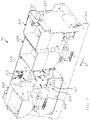
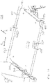
- FIG. 2 shows the coin drawer 30 in a perspective view 1 according to one embodiment.
- the coin drawer 30 includes several docking stations 300, for example four, which are arranged on a carrier 301.
- the carrier 301 can be formed as a sheet metal or plastic part.
- the docking stations 300 can each include a cover plate 302, which is integrated in one piece into the carrier 301 (see the two in 2 right docking stations 300).
- Cover sheet 302 can be designed as the upper side of a sheet metal base 303, which is placed on the carrier 301 and firmly connected to it (see the two in 2 left docking stations 300).
- a storage device 400 is detachably attached to a respective docking station 300 .
- the construction of the storage devices 400 is described in more detail below with reference to FIG Figures 4 to 7 explained.
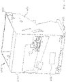
- the cover plate 302 of the docking station 300 which is thus almost completely visible, comprises a first guide device 304 in the form of four slots, for example.
- the slots are also off in view VIII
- Each slot 304 may be formed in the shape of a keyhole. That is, slot 304 has an in 8 circular opening 305 shown in more detail and a channel 306 opening into it.
- the docking station 300 also includes a locking device 307 (see 2 , 3 and 8th ) for attaching the storage device 400 to the docking station 300, as will be explained in more detail below.
- the locking device 307 comprises a lever 308. This is, as in FIGS Figures 8 and 9 shown articulated on the underside of the cover plate 302 in a pivot point 313.
- Lever 308 may have a Z-shape, for example.
- the lever 308 carries a link element in the form of a pin 309 (see Fig. 3 ) and at its other end a handle 310. Both the pin 309 and the handle 310 protrude upwards from the lever 308 through a respectively assigned slot 311 or 312 of the cover plate 302.
- the handle 310 together with the slot 312, forms an over-center mechanism, which will be explained in more detail below.
- the storage device 400 includes a receiving container 401.
- the receiving container 401 can include a funnel 403 into which the coins can be filled from above.
- the storage device 400 can have a counting device 402 which, because it is covered, is only indicated by dashed lines.
- the counting device 402 is set up to count a defined quantity of coins from the funnel 403 and to output them to an output chute, which is not shown in any more detail.
- the counting device 402 can have a sensor, for example an optical sensor.
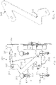
- FIG. 4 shows the storage device 400.
- FIG 4 in an oblique view from below.
- a part of a second guide device 404 is shown there in the form of a screw, which is screwed into a base plate 405 of the storage device 400 .
- the screw 404 includes a screw head 414. It is noted that only one screw 404 is shown. Further screws 404 (not shown) are screwed in at the position of the screw holes 413 before the storage device 400 is mounted on the associated docking station 300 . The screws 404 together form the second guide device 404.
- the storage device 400 has a socket 415.
- the socket 415 is arranged on a rear side 416 of the receptacle 401 .
- the socket 415 corresponds to the plug 315 (see 3 ), ie, the plug 315 and socket 415 are engageable with each other for electrical connection.
- About the connector 315 and the Socket 415 is used to supply power to the counting device 402 when the automated teller machine 1 is in an operating state and/or corresponding control signals can be transmitted via the electrical connection.
- the plug 315 could be arranged on the storage device 400 and the socket 415 on the rear wall 314 .
- FIG. 6 shows the base plate 405 in a perspective view obliquely from above.
- 7 shows the receiving container 401 diagonally from below (without base plate).
- the base plate 405 is clipped onto the receptacle 401 .
- the base plate 405 comprises spring-elastic tabs 406 and spring-elastic hooks 407 which can be releasably engaged with corresponding elements 408 on the underside of the receptacle 401 . Only two of the corresponding engagement elements 408 are shown for simplicity of illustration.
- the base plate 405 has a link 409 in the form of a groove.
- the groove 409 is composed of a first section 410 and a second section 411 .
- the first section 410 extends from an outer edge 412 of the base plate 405 in the direction of the center of the base plate 405.
- the second section 411 runs at an angle relative to the first section 410, for example at an angle of 90°.
- the groove 409 or the sections 410, 411 can be straight or curved.
- the assembly of the storage device 400 as in particular in figure 5 , shown on the associated docking station 300, as in particular in 3 shown, explained:
- the storage device 400 is placed in the vertical direction on the cover plate 302, with the screw heads 414 then passing through the corresponding openings 305 (see 8 ) in the slots 304 in the vertical direction.
- the storage device 400 is pushed horizontally in the direction of the rear wall 314 on the cover plate 302 .
- This direction also referred to here as the direction of insertion, is identified by the reference symbol E in 3 designated.
- the base plate 405 slides on the cover plate 302.
- the pin 309 arrives in the first section 410 of the groove 409. Threading the pin 309 into the first section 410 can be supported by insertion bevels 410a at the entrance of the first section 410.
- the first section 410 extends in the insertion direction E. It should be noted that the pin 309 and the handle 310 in 3 already shown in the locked position. In their unlocked position, as required for the insertion or insertion of the storage device 400, these are each on an in 3 right-hand end of the slots 311 and 312 respectively.
- the pin 309 reaches an intermediate position P1 in which it abuts against the end wall 410b of the first section 410. Any further movement of storage device 400 in the direction of insertion E is then blocked and requires actuation of locking device 307.
- the handle 310 is manually removed from its in 3 not shown right location in its in 3 spent left position shown. In doing so, the cone 309 into the second section 411 (see figure 5 ) shifted, taking up the end position designated P2. In this end position of the pin 309 there is a form fit between it and opposite walls 417a, 417b of the second section 411, as in figure 5 shown.
- the form fit here refers to the in 3 E-direction of insertion of the storage device 400.
- the socket 415 With the movement of the pin 309 from the intermediate position P1 to the end position P2 and the corresponding movement of the storage device 400, the socket 415 finally moves up against the plug 315, so that the plug 315 is inserted into the socket 415. This creates an electrical connection between them.
- the storage device 400 is locked to the docking station 300 with the aid of the locking device 307, i.e. firmly attached to it, so that relative movement is blocked in all six degrees of freedom.
- the locking device 307 is in its locking position.
- the slot 312 is preferably such that it comprises a first section 318 and a second section 319, as in FIG 8 shown.
- a distance D between the first section 318 and the pivot point 313 is dimensioned such that the lever 308, in particular a V-shaped section 320 of the same, is spread apart in a spring-elastic manner as long as the handle 319 moves in the first section 318 of the slot 312. This creates frictional forces between the handle 310 and an edge region of the first section 318 of the slot 312. The operator feels accordingly when moving the handle 310 whose position designated 321, which corresponds to an unlocked position of the locking device 307, a resistance.
- the locking device 307 ensures that the electrical connection between the plug 315 and the socket 415 is maintained. An electrical decoupling can only take place if the locking device 307 has been unlocked beforehand.
- the handle 310 is advantageously located in front of the storage device 400 in the insertion direction E, as shown in FIG 2 to see, and can thus be easily reached and operated by an operator.
- a corresponding storage device 400 is removed and reinserted in particular with the aim of refilling the storage device 400 with coins. Furthermore, a defective storage device 400 can be exchanged in the same way.
- the coin drawer 30 is inserted into the machine housing 10 with the aid of the rail system mentioned (see FIG 1 ) moved in.
- the carrier 301 can be part of this rail system.
- the insertion of the coin drawer 30 takes place in the insertion direction denoted by F.
- the storage devices 400 can be arranged in a row in the coin drawer 30 along the insertion direction F.
- the coin drawer 30 can include a locking plate 323 .
- the locking plate 323 is flush with the rear wall of the machine housing 10 when the coin drawer 30 is pushed in. In this state, the coin drawer 30 can be locked to the machine housing 10 using a lock 324 .
- the coin drawer 30, in particular the coins stored in it, is thus protected from unauthorized access.
- FIG. 10 shows the view 3 , but showing a coin drawer 30 according to an example not in accordance with the invention. Below is only the relevant differences compared to the embodiment according to the Figures 3 - 9 received.
- Docking station 300 has hooks 504 in place of slots 304 .
- tabs 505 can be provided.
- the hooks 504 and lugs 505 can be produced by bending out of the cover plate 302.
- FIG 11 shows a storage device 400, which consists of the coin drawer 30 according to FIG 10 was taken. This corresponds to the storage device 400 from FIG 4 , but with the difference that the bottom plate has a plate body 604, which acts as a second guide means.
- the plate body 604 is, as in the embodiment according to the Figures 6 and 7 , attached to the receptacle 401. However, here the attachment can also be done with the help of screws 640 instead of the clips.
- the plate body 604 includes a base body 641, at one end of which a widened portion 642 is provided.
- the base body 641 also includes part of a locking device 307, namely an opening 609.
- the opening 609 can be designed as a breakthrough, as shown. Alternatively, it can be designed as a pocket that is accessible from below.
- the opening 609 or the wall delimiting it forms a counter-lock for a corresponding lock which will be explained in more detail below.
- FIG. 13 shows the base plate 604 in an end position of the storage device 400 in a perspective view obliquely from above, but without showing the receiving container 401 for reasons of a better overview.
- a further part of the locking device 307 can be seen in particular.
- This includes in addition to the opening 604 (see 12 and 13 ) a lever 540, which is designed in the form of a leaf spring.
- the leaf spring 540 is attached at one end to the underside of the cover plate 302, in particular by means of one or more rivets 541.
- the leaf spring 540 has a catch in the form of a nose 509 bent out of the main plane of extension of the leaf spring 540 .
- the leaf spring 540 includes a free end 542 (see 14 ).
- the free end 542 protrudes in a horizontal plane through an opening 543 from a side plate 544 of the pedestal 303 (see 10 and 14 ) forward, ie towards an operator person out.
- the free end 542 is therefore in front of the storage device 400 in the insertion direction E, as in FIG 10 shown, and can thus be easily reached and operated by an operator.
- the storage device 400 is set down on the cover plate 302 in the vertical direction, the plate body 604 thereby coming to rest on the cover plate 302 .
- the storage device 400 is then slid exclusively linearly along the insertion direction E on the cover plate 302 .
- the movement of the plate body 604 is guided by the hooks 504 and the tabs 505, which are in a direction Q transverse to the direction of insertion (see 13 ) are arranged on both sides of the base body 641 of the plate body 604 .
- the plate body 604 also comes into engagement with the hooks 504 in the vertical direction, in particular in the vertical direction, with two hooks 504 in particular touching the thickened section 642 and in particular one hook 504 touching the end 643 of the Plate body 604. This engagement ensures that tilting or pivoting of the plate body 604 and thus the entire storage device 400 relative to the docking station 300 is blocked.
- the plug 315 moves into the socket 415 and establishes the electrical connection.
- the opening 609 is also arranged above the nose 509 .
- the lug 509 is run over by the plate body 604 and is thus pressed downwards. As soon as the opening 609 is arranged over the lug 509, it snaps back resiliently and thus engages in the opening 609.
- the lug 509 then blocks a return movement of the storage device 400 or locks it with the docking station 300 in a direction opposite to the insertion direction E. In this locking position, movement of the storage device 400 relative to the docking station 300 is blocked in all six degrees of freedom.
- the operator In order to remove the storage device 400 again, the operator must press on the free end 542 . This leads to a bending of the leaf spring 540, as a result of which the lug 509 disengages from the opening 609 in the base plate 604. The storage device 400 can now be moved counter to the insertion direction E again.
Landscapes
- Physics & Mathematics (AREA)
- General Physics & Mathematics (AREA)
- Business, Economics & Management (AREA)
- Accounting & Taxation (AREA)
- Finance (AREA)
- Engineering & Computer Science (AREA)
- General Engineering & Computer Science (AREA)
- Mechanical Engineering (AREA)
- Control Of Vending Devices And Auxiliary Devices For Vending Devices (AREA)
- Pile Receivers (AREA)
Claims (10)
- Guichet automatique bancaire (1) destiné à distribuer des espèces à un client, comprenant :une station d'accueil (300) comportant un premier dispositif de guidage (304, 504),un dispositif de stockage (400) destiné à stocker de la monnaie sous forme de pièces, comportant un second dispositif de guidage (404, 604),dans lequel les premier et second dispositifs de guidage (304, 504 ; 404, 604) sont conçus pour être amenés en prise l'un avec l'autre d'une manière telle que le dispositif de stockage (400) puisse se déplacer d'une manière exclusivement linéaire par rapport à la station d'accueil (300), etun dispositif de verrouillage (307) qui est conçu, à des fins de fixation du dispositif de stockage (400) à la station d'accueil (300), pour verrouiller le dispositif de stockage (400) à la station d'accueil (300) dans une position d'extrémité en direction d'une extrémité du déplacement exclusivement linéaire, dans lequel :le dispositif de verrouillage (307) est conçu pour déplacer le dispositif de stockage (400) dans la position d'extrémité et pour le verrouiller à la station d'accueil (300) au niveau de cette position,le dispositif de verrouillage (307) comprend un guide fendu (409) et un élément de guidage fendu correspondant (309), dans lequel l'élément de guidage fendu (309) peut être déplacé dans le guide fendu (409) à des fins de verrouillage du dispositif de stockage (400) à la station d'accueil (300) et de déplacement du dispositif de stockage (400) dans la position d'extrémité, etle guide fendu (409) est formé sur une plaque inférieure (405) du dispositif de stockage (400) et dans lequel un levier (308) qui est supporté pivotant sur la station d'accueil (300) comprend l'élément de guidage fendu (309), dans lequel le levier (308) peut pivoter à des fins de verrouillage du dispositif de stockage (400) à la station d'accueil (300).
- Guichet automatique bancaire selon la revendication 1,
comprenant
une prise femelle (415) et une fiche (315) conçue pour être introduite dans la prise femelle (415) à des fins d'établissement d'une connexion électrique, dans lequel l'introduction de la fiche (315) dans la prise femelle (415) est accomplie par le déplacement exclusivement linéaire du dispositif de stockage (400) par rapport à la station d'accueil (300). - Guichet automatique bancaire selon la revendication 2,
comprenant
une plaque arrière (314), dans lequel la plaque arrière (314) comprend l'une de la fiche (315) et de la prise femelle (415), et le dispositif de stockage (400) comprend l'autre de la fiche (315) et de la prise femelle (415). - Guichet automatique bancaire selon la revendication 2 ou la revendication 3,
dans lequel
dans la position d'extrémité, la fiche (315) est introduite dans la prise femelle (415). - Guichet automatique bancaire selon l'une des revendications 1 à 4,
dans lequel
le dispositif de verrouillage (307) comprend un mécanisme à point mort. - Guichet automatique bancaire selon la revendication 5,
dans lequel
le levier (308), conjointement avec une fente (312) ménagée dans un élément de recouvrement (302) de la station d'accueil (300), forme le mécanisme à point mort. - Guichet automatique bancaire selon l'une des revendications 1 à 6,
comprenant
des fentes (304) et des broches (404) qui sont conçues pour venir en prise avec une fente respective des fentes (304) et/ou pour venir en prise derrière une partie de bord (317), qui confine une fente respective (304), sur au moins une partie du déplacement exclusivement linéaire du dispositif de stockage (400) par rapport à la station d'accueil (300), dans lequel le premier dispositif de guidage comprend les unes des fentes (304) et des broches (404), et le second dispositif de guidage comprend les autres des fentes (304) et des broches (404). - Guichet automatique bancaire selon l'une des revendications 1 à 7,
dans lequel
le dispositif de stockage (400) comprend un contenant de stockage (401) destiné à la monnaie sous forme de pièces et la plaque inférieure (405), qui est montée, en particulier de manière démontable, sur le contenant de stockage (401), et/ou dans lequel la station d'accueil (300) comprend un élément de recouvrement (302), sur lequel le dispositif de stockage (400), en particulier sa plaque inférieure (405), est supporté de manière coulissante par rapport au déplacement exclusivement linéaire du dispositif de stockage (400) par rapport à la station d'accueil (300). - Guichet automatique bancaire selon la revendication 8,
dans lequel
la plaque inférieure (405) comprend l'un des premier et second dispositifs de guidage (304, 504 ; 404, 604), et l'élément de recouvrement (302) comprend l'autre des premier et second dispositifs de guidage (304, 504 ; 404, 604). - Guichet automatique bancaire selon l'une des revendications 1 à 9,
comprenant
un boîtier de guichet (10) et un plateau pour pièces (30) prévu pour pouvoir se déplacer de manière coulissante dans le boîtier de guichet (10) et hors de ce dernier, dans lequel le plateau pour pièces (30) comprend la station d'accueil (300) et le dispositif de stockage (400), le dispositif de stockage (400) étant monté de manière démontable sur la station d'accueil (300).
Applications Claiming Priority (2)
| Application Number | Priority Date | Filing Date | Title |
|---|---|---|---|
| DE102015122370.8A DE102015122370A1 (de) | 2015-12-21 | 2015-12-21 | Geldautomat |
| PCT/EP2016/074226 WO2017108220A1 (fr) | 2015-12-21 | 2016-10-10 | Distributeur automatique de monnaie |
Publications (2)
| Publication Number | Publication Date |
|---|---|
| EP3394840A1 EP3394840A1 (fr) | 2018-10-31 |
| EP3394840B1 true EP3394840B1 (fr) | 2023-01-11 |
Family
ID=57124020
Family Applications (1)
| Application Number | Title | Priority Date | Filing Date |
|---|---|---|---|
| EP16779095.5A Active EP3394840B1 (fr) | 2015-12-21 | 2016-10-10 | Distributeur automatique de monnaie |
Country Status (4)
| Country | Link |
|---|---|
| EP (1) | EP3394840B1 (fr) |
| CN (1) | CN108475455B (fr) |
| DE (1) | DE102015122370A1 (fr) |
| WO (1) | WO2017108220A1 (fr) |
Family Cites Families (11)
| Publication number | Priority date | Publication date | Assignee | Title |
|---|---|---|---|---|
| US2858921A (en) * | 1953-10-15 | 1958-11-04 | Nat Vendors Inc | Coin apparatus |
| US3942543A (en) * | 1974-06-17 | 1976-03-09 | Pan Nova, Inc. | Change mechanism for a gasoline dispense or the like |
| DE2455772A1 (de) * | 1974-11-26 | 1976-08-12 | Alfred Krauth Apparatebau Kg P | Muenzrueckgabegeraet mit auswechselbarer muenzkassette |
| FR2587134B1 (fr) * | 1985-09-12 | 1988-07-08 | Landis Gyr | Compartiment caisse en particulier pour appareils a monnaie tels que les publiphones |
| US5619932A (en) * | 1993-09-30 | 1997-04-15 | Cubic Toll Systems, Inc. | Vault for storing coins and/or tokens |
| US5716154A (en) * | 1996-08-26 | 1998-02-10 | General Motors Corporation | Attachment device |
| US5873446A (en) * | 1996-11-29 | 1999-02-23 | Paokai Electronic Enterprise Co., Ltd. | Coin box assembly |
| ES2231456T3 (es) * | 2000-01-24 | 2005-05-16 | Wincor Nixdorf International Gmbh | Cajero automatico. |
| AT10716U1 (de) * | 2008-03-04 | 2009-08-15 | Keba Ag | Aufnahmebehälter für zahlungsmittel sowie selbstkassierender automat zur aufnahme eines solchen aufnahmebehälters |
| DE102011054842A1 (de) * | 2011-10-27 | 2013-05-02 | Wincor Nixdorf International Gmbh | Vorrichtung zur Handhabung von Wertscheinen und/oder Münzen sowie Verfahren zur Initialisierung und zum Betrieb einer solchen Vorrichtung |
| EP2709077B1 (fr) * | 2012-09-14 | 2016-12-14 | Wincor Nixdorf International GmbH | Coffret à argent doté de deux unités de verrouillage |
-
2015
- 2015-12-21 DE DE102015122370.8A patent/DE102015122370A1/de not_active Withdrawn
-
2016
- 2016-10-10 CN CN201680075212.3A patent/CN108475455B/zh active Active
- 2016-10-10 EP EP16779095.5A patent/EP3394840B1/fr active Active
- 2016-10-10 WO PCT/EP2016/074226 patent/WO2017108220A1/fr not_active Ceased
Also Published As
| Publication number | Publication date |
|---|---|
| CN108475455A (zh) | 2018-08-31 |
| CN108475455B (zh) | 2020-10-23 |
| WO2017108220A1 (fr) | 2017-06-29 |
| EP3394840A1 (fr) | 2018-10-31 |
| DE102015122370A1 (de) | 2017-06-22 |
Similar Documents
| Publication | Publication Date | Title |
|---|---|---|
| EP2782478A1 (fr) | Dispositif de fixation doté d'un écarteur | |
| EP0678209B1 (fr) | Machine a sous | |
| DE3706829C2 (fr) | ||
| DE10106272C1 (de) | Verteilungssystem der Energietechnik zur Versorgung elektrischer Verbraucher | |
| DE202017107317U1 (de) | Stapelbarer Systembehälter und Transportsystem | |
| WO1993018490A1 (fr) | Tiroir-caisse | |
| EP0902386B1 (fr) | Lecteur de carte | |
| EP0121170A1 (fr) | Conteneur d'argent transportable actionné par une caisse enregistreuse | |
| DE102015122370A1 (de) | Geldautomat | |
| EP3543967B1 (fr) | Stockage de pièces de monnaie | |
| DE102009056650A1 (de) | Verriegelungselement für einen Einschubserver, Einschubserver und Rackanordnung | |
| DE10254515A1 (de) | Magazin zum Bereitstellen von Transportwagen | |
| DE202015002795U1 (de) | Verriegelungsvorrichtung einer Steckbaugruppe | |
| DE4338611C2 (de) | Geldspielgerät | |
| EP2814007B1 (fr) | Coffret à billets de banque avec un élément de blocage pour empêcher des mouvements involontaires de l'unité de pression | |
| WO1992005520A1 (fr) | Appareil commande par ordinateur | |
| EP1731914A1 (fr) | Unité fonctionnelle pour un appareil électrique ou électronique | |
| DE3235011A1 (de) | Muenzbetaetigtes bildschirm-spielgeraet | |
| EP3479365B1 (fr) | Guichet automatique bancaire | |
| DE4135774A1 (de) | Aufnahmevorrichtung fuer transportable geldkassetten von registrierkassen | |
| EP1579395A1 (fr) | Cadenas a piece de consigne | |
| DE102024110580A1 (de) | Geldkassette mit Verriegelungsmechanismus | |
| DE69510946T2 (de) | Ausgabevorrichtung | |
| DE3047089A1 (de) | Verriegelungsvorrichtung fuer baugruppen | |
| DE102004023679A1 (de) | Verfahren zum wieder entnehmbaren Befestigen eines Dienstleistungsautomaten in einer vertikalen Lage sowie Anordnung hierzu |
Legal Events
| Date | Code | Title | Description |
|---|---|---|---|
| STAA | Information on the status of an ep patent application or granted ep patent |
Free format text: STATUS: THE INTERNATIONAL PUBLICATION HAS BEEN MADE |
|
| PUAI | Public reference made under article 153(3) epc to a published international application that has entered the european phase |
Free format text: ORIGINAL CODE: 0009012 |
|
| STAA | Information on the status of an ep patent application or granted ep patent |
Free format text: STATUS: REQUEST FOR EXAMINATION WAS MADE |
|
| 17P | Request for examination filed |
Effective date: 20180613 |
|
| AK | Designated contracting states |
Kind code of ref document: A1 Designated state(s): AL AT BE BG CH CY CZ DE DK EE ES FI FR GB GR HR HU IE IS IT LI LT LU LV MC MK MT NL NO PL PT RO RS SE SI SK SM TR |
|
| AX | Request for extension of the european patent |
Extension state: BA ME |
|
| DAV | Request for validation of the european patent (deleted) | ||
| DAX | Request for extension of the european patent (deleted) | ||
| STAA | Information on the status of an ep patent application or granted ep patent |
Free format text: STATUS: EXAMINATION IS IN PROGRESS |
|
| 17Q | First examination report despatched |
Effective date: 20200717 |
|
| GRAP | Despatch of communication of intention to grant a patent |
Free format text: ORIGINAL CODE: EPIDOSNIGR1 |
|
| STAA | Information on the status of an ep patent application or granted ep patent |
Free format text: STATUS: GRANT OF PATENT IS INTENDED |
|
| INTG | Intention to grant announced |
Effective date: 20211207 |
|
| GRAS | Grant fee paid |
Free format text: ORIGINAL CODE: EPIDOSNIGR3 |
|
| GRAA | (expected) grant |
Free format text: ORIGINAL CODE: 0009210 |
|
| STAA | Information on the status of an ep patent application or granted ep patent |
Free format text: STATUS: THE PATENT HAS BEEN GRANTED |
|
| AK | Designated contracting states |
Kind code of ref document: B1 Designated state(s): AL AT BE BG CH CY CZ DE DK EE ES FI FR GB GR HR HU IE IS IT LI LT LU LV MC MK MT NL NO PL PT RO RS SE SI SK SM TR |
|
| RAP1 | Party data changed (applicant data changed or rights of an application transferred) |
Owner name: KEBA HANDOVER AUTOMATION GMBH |
|
| REG | Reference to a national code |
Ref country code: GB Ref legal event code: FG4D Free format text: NOT ENGLISH |
|
| REG | Reference to a national code |
Ref country code: CH Ref legal event code: EP |
|
| REG | Reference to a national code |
Ref country code: DE Ref legal event code: R096 Ref document number: 502016015544 Country of ref document: DE |
|
| REG | Reference to a national code |
Ref country code: IE Ref legal event code: FG4D Free format text: LANGUAGE OF EP DOCUMENT: GERMAN |
|
| REG | Reference to a national code |
Ref country code: AT Ref legal event code: REF Ref document number: 1543883 Country of ref document: AT Kind code of ref document: T Effective date: 20230215 |
|
| REG | Reference to a national code |
Ref country code: LT Ref legal event code: MG9D |
|
| REG | Reference to a national code |
Ref country code: NL Ref legal event code: MP Effective date: 20230111 |
|
| PG25 | Lapsed in a contracting state [announced via postgrant information from national office to epo] |
Ref country code: NL Free format text: LAPSE BECAUSE OF FAILURE TO SUBMIT A TRANSLATION OF THE DESCRIPTION OR TO PAY THE FEE WITHIN THE PRESCRIBED TIME-LIMIT Effective date: 20230111 |
|
| PG25 | Lapsed in a contracting state [announced via postgrant information from national office to epo] |
Ref country code: RS Free format text: LAPSE BECAUSE OF FAILURE TO SUBMIT A TRANSLATION OF THE DESCRIPTION OR TO PAY THE FEE WITHIN THE PRESCRIBED TIME-LIMIT Effective date: 20230111 Ref country code: PT Free format text: LAPSE BECAUSE OF FAILURE TO SUBMIT A TRANSLATION OF THE DESCRIPTION OR TO PAY THE FEE WITHIN THE PRESCRIBED TIME-LIMIT Effective date: 20230511 Ref country code: NO Free format text: LAPSE BECAUSE OF FAILURE TO SUBMIT A TRANSLATION OF THE DESCRIPTION OR TO PAY THE FEE WITHIN THE PRESCRIBED TIME-LIMIT Effective date: 20230411 Ref country code: LV Free format text: LAPSE BECAUSE OF FAILURE TO SUBMIT A TRANSLATION OF THE DESCRIPTION OR TO PAY THE FEE WITHIN THE PRESCRIBED TIME-LIMIT Effective date: 20230111 Ref country code: LT Free format text: LAPSE BECAUSE OF FAILURE TO SUBMIT A TRANSLATION OF THE DESCRIPTION OR TO PAY THE FEE WITHIN THE PRESCRIBED TIME-LIMIT Effective date: 20230111 Ref country code: HR Free format text: LAPSE BECAUSE OF FAILURE TO SUBMIT A TRANSLATION OF THE DESCRIPTION OR TO PAY THE FEE WITHIN THE PRESCRIBED TIME-LIMIT Effective date: 20230111 Ref country code: ES Free format text: LAPSE BECAUSE OF FAILURE TO SUBMIT A TRANSLATION OF THE DESCRIPTION OR TO PAY THE FEE WITHIN THE PRESCRIBED TIME-LIMIT Effective date: 20230111 |
|
| PG25 | Lapsed in a contracting state [announced via postgrant information from national office to epo] |
Ref country code: SE Free format text: LAPSE BECAUSE OF FAILURE TO SUBMIT A TRANSLATION OF THE DESCRIPTION OR TO PAY THE FEE WITHIN THE PRESCRIBED TIME-LIMIT Effective date: 20230111 Ref country code: PL Free format text: LAPSE BECAUSE OF FAILURE TO SUBMIT A TRANSLATION OF THE DESCRIPTION OR TO PAY THE FEE WITHIN THE PRESCRIBED TIME-LIMIT Effective date: 20230111 Ref country code: IS Free format text: LAPSE BECAUSE OF FAILURE TO SUBMIT A TRANSLATION OF THE DESCRIPTION OR TO PAY THE FEE WITHIN THE PRESCRIBED TIME-LIMIT Effective date: 20230511 Ref country code: GR Free format text: LAPSE BECAUSE OF FAILURE TO SUBMIT A TRANSLATION OF THE DESCRIPTION OR TO PAY THE FEE WITHIN THE PRESCRIBED TIME-LIMIT Effective date: 20230412 Ref country code: FI Free format text: LAPSE BECAUSE OF FAILURE TO SUBMIT A TRANSLATION OF THE DESCRIPTION OR TO PAY THE FEE WITHIN THE PRESCRIBED TIME-LIMIT Effective date: 20230111 |
|
| REG | Reference to a national code |
Ref country code: DE Ref legal event code: R097 Ref document number: 502016015544 Country of ref document: DE |
|
| PG25 | Lapsed in a contracting state [announced via postgrant information from national office to epo] |
Ref country code: SM Free format text: LAPSE BECAUSE OF FAILURE TO SUBMIT A TRANSLATION OF THE DESCRIPTION OR TO PAY THE FEE WITHIN THE PRESCRIBED TIME-LIMIT Effective date: 20230111 Ref country code: RO Free format text: LAPSE BECAUSE OF FAILURE TO SUBMIT A TRANSLATION OF THE DESCRIPTION OR TO PAY THE FEE WITHIN THE PRESCRIBED TIME-LIMIT Effective date: 20230111 Ref country code: EE Free format text: LAPSE BECAUSE OF FAILURE TO SUBMIT A TRANSLATION OF THE DESCRIPTION OR TO PAY THE FEE WITHIN THE PRESCRIBED TIME-LIMIT Effective date: 20230111 Ref country code: DK Free format text: LAPSE BECAUSE OF FAILURE TO SUBMIT A TRANSLATION OF THE DESCRIPTION OR TO PAY THE FEE WITHIN THE PRESCRIBED TIME-LIMIT Effective date: 20230111 Ref country code: CZ Free format text: LAPSE BECAUSE OF FAILURE TO SUBMIT A TRANSLATION OF THE DESCRIPTION OR TO PAY THE FEE WITHIN THE PRESCRIBED TIME-LIMIT Effective date: 20230111 |
|
| PLBE | No opposition filed within time limit |
Free format text: ORIGINAL CODE: 0009261 |
|
| STAA | Information on the status of an ep patent application or granted ep patent |
Free format text: STATUS: NO OPPOSITION FILED WITHIN TIME LIMIT |
|
| PG25 | Lapsed in a contracting state [announced via postgrant information from national office to epo] |
Ref country code: SK Free format text: LAPSE BECAUSE OF FAILURE TO SUBMIT A TRANSLATION OF THE DESCRIPTION OR TO PAY THE FEE WITHIN THE PRESCRIBED TIME-LIMIT Effective date: 20230111 |
|
| 26N | No opposition filed |
Effective date: 20231012 |
|
| PG25 | Lapsed in a contracting state [announced via postgrant information from national office to epo] |
Ref country code: SI Free format text: LAPSE BECAUSE OF FAILURE TO SUBMIT A TRANSLATION OF THE DESCRIPTION OR TO PAY THE FEE WITHIN THE PRESCRIBED TIME-LIMIT Effective date: 20230111 |
|
| PG25 | Lapsed in a contracting state [announced via postgrant information from national office to epo] |
Ref country code: IT Free format text: LAPSE BECAUSE OF FAILURE TO SUBMIT A TRANSLATION OF THE DESCRIPTION OR TO PAY THE FEE WITHIN THE PRESCRIBED TIME-LIMIT Effective date: 20230111 Ref country code: MC Free format text: LAPSE BECAUSE OF FAILURE TO SUBMIT A TRANSLATION OF THE DESCRIPTION OR TO PAY THE FEE WITHIN THE PRESCRIBED TIME-LIMIT Effective date: 20230111 |
|
| REG | Reference to a national code |
Ref country code: BE Ref legal event code: MM Effective date: 20231031 |
|
| PG25 | Lapsed in a contracting state [announced via postgrant information from national office to epo] |
Ref country code: LU Free format text: LAPSE BECAUSE OF NON-PAYMENT OF DUE FEES Effective date: 20231010 |
|
| GBPC | Gb: european patent ceased through non-payment of renewal fee |
Effective date: 20231010 |
|
| PG25 | Lapsed in a contracting state [announced via postgrant information from national office to epo] |
Ref country code: LU Free format text: LAPSE BECAUSE OF NON-PAYMENT OF DUE FEES Effective date: 20231010 |
|
| PG25 | Lapsed in a contracting state [announced via postgrant information from national office to epo] |
Ref country code: GB Free format text: LAPSE BECAUSE OF NON-PAYMENT OF DUE FEES Effective date: 20231010 |
|
| PG25 | Lapsed in a contracting state [announced via postgrant information from national office to epo] |
Ref country code: GB Free format text: LAPSE BECAUSE OF NON-PAYMENT OF DUE FEES Effective date: 20231010 Ref country code: FR Free format text: LAPSE BECAUSE OF NON-PAYMENT OF DUE FEES Effective date: 20231031 |
|
| PG25 | Lapsed in a contracting state [announced via postgrant information from national office to epo] |
Ref country code: BE Free format text: LAPSE BECAUSE OF NON-PAYMENT OF DUE FEES Effective date: 20231031 |
|
| PG25 | Lapsed in a contracting state [announced via postgrant information from national office to epo] |
Ref country code: IE Free format text: LAPSE BECAUSE OF NON-PAYMENT OF DUE FEES Effective date: 20231010 |
|
| PG25 | Lapsed in a contracting state [announced via postgrant information from national office to epo] |
Ref country code: IE Free format text: LAPSE BECAUSE OF NON-PAYMENT OF DUE FEES Effective date: 20231010 |
|
| PG25 | Lapsed in a contracting state [announced via postgrant information from national office to epo] |
Ref country code: BG Free format text: LAPSE BECAUSE OF FAILURE TO SUBMIT A TRANSLATION OF THE DESCRIPTION OR TO PAY THE FEE WITHIN THE PRESCRIBED TIME-LIMIT Effective date: 20230111 |
|
| PG25 | Lapsed in a contracting state [announced via postgrant information from national office to epo] |
Ref country code: BG Free format text: LAPSE BECAUSE OF FAILURE TO SUBMIT A TRANSLATION OF THE DESCRIPTION OR TO PAY THE FEE WITHIN THE PRESCRIBED TIME-LIMIT Effective date: 20230111 |
|
| PG25 | Lapsed in a contracting state [announced via postgrant information from national office to epo] |
Ref country code: CY Free format text: LAPSE BECAUSE OF FAILURE TO SUBMIT A TRANSLATION OF THE DESCRIPTION OR TO PAY THE FEE WITHIN THE PRESCRIBED TIME-LIMIT; INVALID AB INITIO Effective date: 20161010 |
|
| PG25 | Lapsed in a contracting state [announced via postgrant information from national office to epo] |
Ref country code: HU Free format text: LAPSE BECAUSE OF FAILURE TO SUBMIT A TRANSLATION OF THE DESCRIPTION OR TO PAY THE FEE WITHIN THE PRESCRIBED TIME-LIMIT; INVALID AB INITIO Effective date: 20161010 |
|
| REG | Reference to a national code |
Ref country code: CH Ref legal event code: U11 Free format text: ST27 STATUS EVENT CODE: U-0-0-U10-U11 (AS PROVIDED BY THE NATIONAL OFFICE) Effective date: 20251101 |
|
| PG25 | Lapsed in a contracting state [announced via postgrant information from national office to epo] |
Ref country code: TR Free format text: LAPSE BECAUSE OF FAILURE TO SUBMIT A TRANSLATION OF THE DESCRIPTION OR TO PAY THE FEE WITHIN THE PRESCRIBED TIME-LIMIT Effective date: 20230111 |
|
| PGFP | Annual fee paid to national office [announced via postgrant information from national office to epo] |
Ref country code: DE Payment date: 20251021 Year of fee payment: 10 |
|
| PGFP | Annual fee paid to national office [announced via postgrant information from national office to epo] |
Ref country code: AT Payment date: 20251021 Year of fee payment: 10 |
|
| PGFP | Annual fee paid to national office [announced via postgrant information from national office to epo] |
Ref country code: CH Payment date: 20251101 Year of fee payment: 10 |