EP3395145B1 - Landwirtschaftlicher schleuderstreuer - Google Patents
Landwirtschaftlicher schleuderstreuer Download PDFInfo
- Publication number
- EP3395145B1 EP3395145B1 EP18401034.6A EP18401034A EP3395145B1 EP 3395145 B1 EP3395145 B1 EP 3395145B1 EP 18401034 A EP18401034 A EP 18401034A EP 3395145 B1 EP3395145 B1 EP 3395145B1
- Authority
- EP
- European Patent Office
- Prior art keywords
- centrifugal spreader
- radar
- radar sensor
- spreading
- spreading disc
- Prior art date
- Legal status (The legal status is an assumption and is not a legal conclusion. Google has not performed a legal analysis and makes no representation as to the accuracy of the status listed.)
- Active
Links
Images


Classifications
-
- A—HUMAN NECESSITIES
- A01—AGRICULTURE; FORESTRY; ANIMAL HUSBANDRY; HUNTING; TRAPPING; FISHING
- A01C—PLANTING; SOWING; FERTILISING
- A01C17/00—Fertilisers or seeders with centrifugal wheels
- A01C17/006—Regulating or dosing devices
- A01C17/008—Devices controlling the quantity or the distribution pattern
-
- A—HUMAN NECESSITIES
- A01—AGRICULTURE; FORESTRY; ANIMAL HUSBANDRY; HUNTING; TRAPPING; FISHING
- A01C—PLANTING; SOWING; FERTILISING
- A01C15/00—Fertiliser distributors
- A01C15/005—Undercarriages, tanks, hoppers, stirrers specially adapted for seeders or fertiliser distributors
- A01C15/008—Aprons; Deflecting plates; Band-spreading attachments
-
- G—PHYSICS
- G01—MEASURING; TESTING
- G01S—RADIO DIRECTION-FINDING; RADIO NAVIGATION; DETERMINING DISTANCE OR VELOCITY BY USE OF RADIO WAVES; LOCATING OR PRESENCE-DETECTING BY USE OF THE REFLECTION OR RERADIATION OF RADIO WAVES; ANALOGOUS ARRANGEMENTS USING OTHER WAVES
- G01S13/00—Systems using the reflection or reradiation of radio waves, e.g. radar systems; Analogous systems using reflection or reradiation of waves whose nature or wavelength is irrelevant or unspecified
- G01S13/02—Systems using reflection of radio waves, e.g. primary radar systems; Analogous systems
- G01S13/50—Systems of measurement based on relative movement of target
- G01S13/58—Velocity or trajectory determination systems; Sense-of-movement determination systems
-
- G—PHYSICS
- G01—MEASURING; TESTING
- G01S—RADIO DIRECTION-FINDING; RADIO NAVIGATION; DETERMINING DISTANCE OR VELOCITY BY USE OF RADIO WAVES; LOCATING OR PRESENCE-DETECTING BY USE OF THE REFLECTION OR RERADIATION OF RADIO WAVES; ANALOGOUS ARRANGEMENTS USING OTHER WAVES
- G01S13/00—Systems using the reflection or reradiation of radio waves, e.g. radar systems; Analogous systems using reflection or reradiation of waves whose nature or wavelength is irrelevant or unspecified
- G01S13/87—Combinations of radar systems, e.g. primary radar and secondary radar
-
- G—PHYSICS
- G01—MEASURING; TESTING
- G01S—RADIO DIRECTION-FINDING; RADIO NAVIGATION; DETERMINING DISTANCE OR VELOCITY BY USE OF RADIO WAVES; LOCATING OR PRESENCE-DETECTING BY USE OF THE REFLECTION OR RERADIATION OF RADIO WAVES; ANALOGOUS ARRANGEMENTS USING OTHER WAVES
- G01S13/00—Systems using the reflection or reradiation of radio waves, e.g. radar systems; Analogous systems using reflection or reradiation of waves whose nature or wavelength is irrelevant or unspecified
- G01S13/88—Radar or analogous systems specially adapted for specific applications
-
- G—PHYSICS
- G01—MEASURING; TESTING
- G01S—RADIO DIRECTION-FINDING; RADIO NAVIGATION; DETERMINING DISTANCE OR VELOCITY BY USE OF RADIO WAVES; LOCATING OR PRESENCE-DETECTING BY USE OF THE REFLECTION OR RERADIATION OF RADIO WAVES; ANALOGOUS ARRANGEMENTS USING OTHER WAVES
- G01S7/00—Details of systems according to groups G01S13/00, G01S15/00, G01S17/00
- G01S7/02—Details of systems according to groups G01S13/00, G01S15/00, G01S17/00 of systems according to group G01S13/00
- G01S7/28—Details of pulse systems
- G01S7/2813—Means providing a modification of the radiation pattern for cancelling noise, clutter or interfering signals, e.g. side lobe suppression, side lobe blanking, null-steering arrays
-
- H—ELECTRICITY
- H01—ELECTRIC ELEMENTS
- H01Q—ANTENNAS, i.e. RADIO AERIALS
- H01Q1/00—Details of, or arrangements associated with, antennas
- H01Q1/52—Means for reducing coupling between antennas; Means for reducing coupling between an antenna and another structure
- H01Q1/526—Electromagnetic shields
Definitions
- the invention relates to an agricultural centrifugal spreader according to the preamble of claim 1.
- Agricultural centrifugal spreaders are typically equipped with two spreading discs, onto which the fertilizer from the slide openings of a storage container is applied and then spread using centrifugal action by means of centrifugal blades arranged on the spreading discs.
- the spreading discs rotate at high speed while working.
- Modern centrifugal spreaders have radar sensors to characterize the spreading fan of the spread material by means of sensors so that the current working width, the geometry of the spreading fan and / or the throwing distance can be determined. Such measurements are carried out in particular with radar waves.
- one or more radar sensors are arranged in the vicinity of the lenses. If only one sensor is present, it is typically designed to be movable in order to be able to detect the entire spreading area of the spreading fan.
- centrifugal spreader are often made of stainless steel or comparable materials, which have sufficient robustness and durability with regard to mechanical and chemical stress. It has been found that such centrifugal disks can lead to faulty measurement signals from the radar sensors if a second centrifugal disk is located in the measuring range of a radar sensor that is assigned to a first centrifugal disk.
- Such a spreader is in WO 2017/041884 A1 disclosed.
- the radar sensors of this centrifugal spreader are arranged in a housing which is transparent to the measuring radiation from the sensors.
- the object of the present invention is to provide a shielding device for an agricultural centrifugal spreader which prevents such erroneous measurement signals.
- the shielding device is arranged at least in a possible visual axis between the radar sensor and a second spreading disc of the centrifugal spreader and / or its throwing blades. It is therefore provided that the shielding device blocks one or more direct lines of sight between the radar sensor, in particular the center of the radiation area of the housing of the radar sensor, and the second lens and / or the throwing vanes or the second lens, so that no undesired backscattering of radar waves can be done on the second lens.
- the second lens is the lens to which the radar sensor under consideration is not assigned.
- the shielding device is arranged at least in the line of sight between the radar sensor and the outer end of the throwing blades of the second spreading disc when the rear throwing blade, as seen in the direction of travel, is oriented parallel to the direction of travel. Due to the limited opening angle of the radiation area of the radar waves of the radar sensor, the second centrifugal disc is primarily located in the measuring range of a radar sensor of a first centrifugal disc when the throwing vane, i.e. the most outstanding component of the centrifugal disc, is oriented rearwards in the opposite direction to the direction of travel. In other words, the outermost part of the throwing blade is positioned furthest to the rear relative to the centrifugal spreader or the respective spreading disc.
- the likelihood is greatest that the end of the throwing blade is in the measuring range of at least one radar sensor of the adjacent second spreading disc.
- this is usually the radar sensor which is the smallest distance from the second lens.
- the shielding device at least then in the line of sight between the radar sensor and the outer one
- the end of the throwing blades of the second spreading disc is arranged when the distance between the radar sensor and the throwing blades is in each case minimal. If the distance between the radar sensor and a throwing vane of the adjacent spreading disc is particularly small, the intensity of the backscattered radar waves can be particularly large, so that it can be particularly advantageous that in this position the line of sight between the outer end of the throwing vane and the radar sensor under consideration is blocked.
- the shielding device is made of material absorbing radar waves and is preferably arranged in the plane of symmetry of the centrifugal spreader. It can therefore be provided to manufacture the shielding device from a material that absorbs the radar waves.
- the shielding device is made of material reflecting radar waves and is arranged non-parallel to the plane of symmetry of the centrifugal spreader. If the shielding device is to be constructed in a particularly simple and robust manner, it may be expedient to manufacture it from material that reflects radar waves, such as, for example, stainless steel. In this case it is necessary to arrange the shielding device non-parallel to the plane of symmetry of the centrifugal spreader.
- the second diffusing screen would be shielded by a correspondingly arranged shielding device, but the radar waves would be reflected back and forth by the shielding device arranged parallel to the plane of symmetry in such a way that radar waves can be reflected on the first diffusing screen, which in some circumstances leads to measurement errors.
- the shielding device on Centrifugal spreaders are provided with two shielding devices if an arrangement of radar sensors is assigned to each of the two spreading discs.
- the shielding device blocks all possible lines of sight between the radar sensor and the second spreading disc and / or their throwing blades.
- the shielding device can thus be designed in such a way that any line of sight between the radar sensor of the first spreading disc and the second spreading disc and / or their throwing blades is blocked, so that reflections from radar waves of the radar sensor on the second spreading disc or their throwing blades can be completely prevented.
- a centrifugal spreader 1 according to the invention is shown in Fig. 1 shown.
- This has, inter alia, a container 2 for storing spreading material and in the lower region a first and second spreading disc 3.1, 3.2, each with two throwing blades 4, with which the material in the container 1 can be distributed over the agricultural area to be worked.
- the supply of spreading material to the spreading discs 3 can be controlled for this purpose by means of metering slides 5.
- Radar sensors 6, in this case seven per lens 3, are arranged above the lens and at least approximately concentrically in the circumferential direction of the lens, as a radar sensor arrangement which scans the scatter fan of the respective lens. Fewer or more than seven radar sensors 6 can also be provided per lens and radar sensor arrangement.
- the radar sensors 6 can also be provided to use a single sensor which is arranged pivotably in the circumferential direction of the diffusing screen 3. It can also be provided that one or more radar sensors 6 are assigned to only one of the two lenses 3 and the measured signals are transmitted to the second lens assuming a symmetrical distribution.
- the radar sensors 6 are attached to a holding device 7.
- the holding device 7 is also attached to the centrifugal broadcaster 1, so that the radar sensors 6 are distributed concentrically around the spreading discs.
- the radar sensors are predominantly located on the rear of the centrifugal spreader, so that the radar sensors 6 can apply radar waves to the scattered material thrown backwards.
- the radar sensors 6 are also located slightly above the spreading discs 3 in the vertical direction, so that the sensor arrangement is not hit by the thrown spreading material.
- the radar sensors can also be arranged just as well below the lenses 3.
- the radar sensors 6 apply radar waves to the scattered material, so that the intensity of the measurement signal can be used to infer the amount of material to be thrown into the respective measuring range and / or the frequency of the measurement signal to determine the speed and thus the range of the material being thrown can be closed.
- a comparison of the intensities of the radar sensors 6 of a spreading disc 3.1, 3.2 can be used to infer the amount of spreading material thrown off and / or the distribution characteristic and / or the working width of the respective spreading disc.
- the measurement signals are correspondingly processed in a data processing device (not shown), for example a job computer on the centrifugal spreader 1, with regard to the spread rate, spreading distance and working width and / or further parameters are evaluated and compared with setpoints stored in the job computer, so that in the event of a deviation by means of regulation by setting, for example, centrifugal disc speed, metering slide position and adaptation of the point of application of the spreading material to the spreading discs 3, an actual value adaptation to the setpoints takes place.
- a data processing device for example a job computer on the centrifugal spreader 1
- setpoints stored in the job computer, so that in the event of a deviation by means of regulation by setting, for example, centrifugal disc speed, metering slide position and adaptation of the point of application of the spreading material to the spreading discs 3, an actual value adaptation to the setpoints takes place.
- a circumferential, bow-like protective device 8 is shown, which on the rear side of the centrifugal spreader 1 encloses both the radar sensors 6 and the spreading disks 3 in the horizontal direction.
- the protective device 8 can, as in this case be formed in one piece, but can also consist of two or more parts.
- the protective device 8 is fastened in the areas 9a and 9b to the frame of the centrifugal spreader and by means of a fastening device 10 in the rear area of the container 2.
- a shielding device 11 which is intended to prevent undesired reflections and scattering of radar waves from the innermost of the radar sensors 6 of the radar sensor arrangement of each centrifugal disc on the other centrifugal disc, so that there are no incorrect measurements due to radar waves scattered back on the adjacent diffusing plate can come.
- the bracket device 8, the lenses 3.1 and 3.2 as well as the radar sensors 6 and the shielding device are in Fig. 2 shown in a view from behind.
- the two predominantly vertical sheet metal parts 11.1 and 11.2 are arranged in such a way that the radar sensors 6.1 and 6.2 of the radar sensor arrangements of a first diffusing screen 3.1 and a second diffusing screen 3.2, which are located most inside, are shielded from backscattering on the second and first diffusing screens 3.2 and 3.1, respectively.
- the innermost radar sensors should therefore each be shielded against backscattering of radar waves emitted on the lens, the spreading fan of which is not detected by this radar sensor.
- the sheet metal parts 11.1 and 11.2 of the shielding device 11 are each arranged such that the line of sight between the radar sensor 6.1, 6.2 and the neighboring one Diffuser 3.2, 3.1 is at least partially blocked.
- the sheet metal parts 11.1, 11.2 are arranged obliquely with respect to the centrifugal spreader plane of symmetry A, that is to say not parallel to the plane of symmetry, so that they cannot act as an undesired mirror. If the sheet metal parts were arranged parallel to the plane of symmetry A, backscattering of the second lens could be prevented, for example, but reflections of the emitted radar waves on the sheet metal part 11.1 could result in undesirable measurement errors due to backscattering on the first lens 3.1 and renewed reflection on the sheet metal part 11.1.
- the undesirable effect of backscattering on the second diffusing plate by reflection by means of the sheet metal part 11.1 in or parallel to the plane of symmetry would thus be undesirably transmitted to the first diffusing plate 3.1.
- the shielding device can also be arranged parallel to or lying in the plane of symmetry. In this way, a single shielding device may be sufficient for both sensor arrangements or sensors 6.1, 6.2.
- further sensors 6 can also be protected against undesired backscattering by further shielding devices and or another geometrical configuration of the shielding device 11.
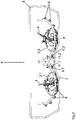
- FIG. 3 A vertical view of the spreading discs 3.1, 3.2, throwing blades 4, radar sensors 6, 6.1, 6.2 and protective bracket 8 is shown in Fig. 3 shown.
- the hatched areas 12.1 and 12.2 form the area shaded by the sheet metal parts 11.1 and 11.2, whereby the throwing blades 4 of the spreading discs 3.1 and 3.2 rotating during operation are at least in the shaded area 12.1 and 12.2 when the distance between the respective throwing blade 4 and the radar sensor 6.1 or 6.2 is minimal.
- the sheet metal parts 11.1, 11.2 can also be dimensioned, for example enlarged or extended to the rear, so that the hatched areas also enlarge and that the throwing blades never leave the hatched areas 12.1, 12.2 and thus during the rotary movement of the the respective lens can be shaded at any time.
- the sheet metal part 11.1, 11.2 or other shielding device can be adapted to the different positions of the movable radar sensor and can either move along or be designed to be stationary.
- the shielding device can, as indicated in the exemplary embodiment, be designed as a sheet metal part 11.1, 11.2.
- any materials, geometries and material thicknesses are conceivable.
Landscapes
- Engineering & Computer Science (AREA)
- Radar, Positioning & Navigation (AREA)
- Remote Sensing (AREA)
- Physics & Mathematics (AREA)
- Computer Networks & Wireless Communication (AREA)
- General Physics & Mathematics (AREA)
- Life Sciences & Earth Sciences (AREA)
- Soil Sciences (AREA)
- Environmental Sciences (AREA)
- Electromagnetism (AREA)
- Catching Or Destruction (AREA)
- Radar Systems Or Details Thereof (AREA)
Description
- Die Erfindung betrifft einen landwirtschaftlichen Schleuderstreuer gemäß dem Oberbegriff des Patentanspruches 1.
- Landwirtschaftliche Schleuderstreuer sind typischerweise mit zwei Streuscheiben ausgestattet, auf welche der Dünger aus Schieberöffnungen eines Vorratsbehälters aufgegeben und anschließend mittels auf den Streuscheiben angeordneten Schleuderschaufeln unter Zentrifugalwirkung ausgestreut wird. Zu diesem Zweck drehen sich die Streuscheiben während der Arbeit mit hoher Geschwindigkeit. Moderne Schleuderstreuer verfügen über Radarsensoren, um den Streufächer des ausgebrachten Guts mittels Sensoren zu charakterisieren, so dass die derzeitige Arbeitsbreite, die Geometrie des Streufächers und/oder die Wurfweite bestimmt werden können. Derartige Messungen werden insbesondere mit Radarwellen durchgeführt. Hierfür sind in der Nähe der Streuscheiben ein oder mehrere Radarsensoren angeordnet. Ist nur ein Sensor vorhanden, so ist dieser typischerweise beweglich ausgestaltet, um den gesamten Streubereich des Streufächers erfassen zu können. Sind mehrere Sensoren vorhanden, so sind diese üblicherweise in Umfangsrichtung des Streufächers derart verteilt, dass auch hierdurch zumindest annähernd der gesamte Streubereich erfasst werden kann. Typischerweise handelt es sich um fünf oder mehr Sensoren pro Scheibe, es können sogar auch 20 oder mehr Sensoren pro Scheibe vorhanden sein. Die Streuscheiben des Schleuderstreuers sind häufig aus Edelstahl oder vergleichbaren Materialien gefertigt, welche eine ausreichende Robustheit und Langlebigkeit in Bezug auf mechanische und chemische Beanspruchung aufweisen. Es hat sich herausgestellt, dass derartige Schleuderscheiben zu fehlerbehafteten Messsignalen der Radarsensoren führen können, wenn sich eine zweite Schleuderscheibe im Messbereich eines Radarsensors, der einer ersten Schleuderscheibe zugeordnet ist, befindet.
- Ein derartiger Schleuderstreuer ist in
WO 2017/041884 A1 offenbart. Die Radarsensoren dieses Schleuderstreuers sind in einem Gehäuse, welches durchlässig ist für die Messstrahlung der Sensoren, angeordnet. - Aufgabe der vorliegenden Erfindung ist es, eine Abschirmvorrichtung für einen landwirtschaftlichen Schleuderstreuer anzugeben, die derartige fehlerbehaftete Messsignale verhindert.
- Diese Aufgabe wird durch den kennzeichnenden Teil des Anspruchs 1 gelöst. Demnach ist vorgesehen, dass die Abschirmvorrichtung zumindest in einer möglichen Sichtachse zwischen dem Radarsensor und einer zweiten Streuscheibe des Schleuderstreuers und/oder deren Wurfschaufeln angeordnet ist. Es ist also vorgesehen, dass die Abschirmvorrichtung eine oder mehrere direkte Sichtlinien zwischen dem Radarsensor, insbesondere dem Zentrum des Abstrahlbereiches des Gehäuses des Radarsensors, und der zweiten Streuscheibe und/oder der oder den Wurfschaufeln der zweiten Streuscheibe blockiert, so dass keine unerwünschten Rückstreuungen von Radarwellen an der zweiten Streuscheibe erfolgen können. Die zweite Streuscheibe ist hierbei jeweils diejenige Streuscheibe, der der jeweils betrachtete Radarsensor nicht zugeordnet ist.
- In einer vorteilhaften Weiterbildung der Erfindung ist vorgesehen, dass die Abschirmvorrichtung zumindest dann in der Sichtachse zwischen dem Radarsensor und dem äußeren Ende der Wurfschaufeln der zweiten Streuscheibe angeordnet ist, wenn die in Fahrtrichtung gesehen hintere Wurfschaufel parallel zur Fahrtrichtung orientiert ist. Aufgrund des begrenzten Öffnungswinkels des Abstrahlbereiches der Radarwellen des Radarsensors befindet sich die zweite Schleuderscheibe vornehmlich dann im Messbereich eines Radarsensors einer ersten Schleuderscheibe, wenn die Wurfschaufel, also das am weitesten herausragende Bauteil der Schleuderscheibe parallel zur Fahrtrichtung nach hinten entgegen der Fahrtrichtung orientiert ist. Mit anderen Worten also der äußerste Teil der Wurfschaufel am weitesten hinten relativ zum Schleuderstreuer bzw. der jeweiligen Streuscheibe platziert ist. In dieser Position ist die Wahrscheinlichkeit am größten, dass das Ende der Wurfschaufel sich im Messbereich zumindest eines Radarsensors der benachbarten zweiten Streuscheibe befindet. Dies ist bei einer typischen konzentrischen Anordnung von mehreren Radarsensoren um das Zentrum einer ersten Streuscheibe normalerweise derjenige Radarsensor, welcher den geringsten Abstand zur zweiten Streuscheibe aufweist.
- Alternativ oder zusätzlich kann vorgesehen sein, dass die Abschirmvorrichtung zumindest dann in der Sichtachse zwischen dem Radarsensor und dem äußeren Ende der Wurfschaufeln der zweiten Streuscheibe angeordnet ist, wenn der Abstand zwischen dem Radarsensor und den Wurfschaufeln jeweils minimal ist. Ist der Abstand zwischen dem Radarsensor und einer Wurfschaufel der benachbarten Streuscheibe besonders gering, so kann die Intensität der zurückgestreuten Radarwellen besonders groß sein, so dass es besonders vorteilhaft sein kann, dass in dieser Position die Sichtlinie zwischen dem äußeren Ende der Wurfschaufel und dem betrachteten Radarsensor blockiert ist.
- In einer möglichen Ausgestaltung der Erfindung ist vorgesehen, dass die Abschirmvorrichtung aus Radarwellen absorbierendem Material gefertigt und vorzugsweise in der Symmetrieebene des Schleuderstreuers angeordnet ist. Es kann also vorgesehen sein, die Abschirmvorrichtung aus einem Material zu fertigen, welches die Radarwellen absorbiert. In diesem Fall ist es besonders vorteilhaft, die Abschirmvorrichtung in der Symmetrieebene des Schleuderstreuers oder parallel hierzu anzuordnen, wenn beide Streuscheiben des Schleuderstreuers über Radarsensoren zur Ermittlung der jeweiligen Verteilcharakteristik verfügen. Auf diese Weise kann bei zwei zur Symmetrieebene symmetrisch angeordneten Streuscheiben und Radarsensoranordnungen der beiden Streuscheiben eine Abschirmvorrichtung für beide Streuscheiben bzw. Radarsensoranordnungen verwendet werden.
- In einer alternativen Ausgestaltung ist vorgesehen, dass die Abschirmvorrichtung aus Radarwellen reflektierendem Material gefertigt und nichtparallel zur Symmetrieebene des Schleuderstreuers angeordnet ist. Wenn die Abschirmvorrichtung besonders einfach und robust aufgebaut sein soll, kann es zweckmäßig sein, sie aus Radarwellen reflektierendem Material, wie beispielsweise Edelstahl, zu fertigen. In diesem Fall ist es erforderlich, die Abschirmvorrichtung nichtparallel zur Symmetrieebene des Schleuderstreuers anzuordnen. Andernfalls würde zwar die zweite Streuscheibe durch eine entsprechend angeordnete Abschirmvorrichtung abgeschirmt, allerdings würden die Radarwellen derart von der parallel zur Symmetrieebene angeordneten Abschirmvorrichtung hin und her reflektiert, dass Radarwellen an der ersten Streuscheibe reflektiert werden können, was unter Umständen zu Messfehlern führt. Für den Fall einer nichtparallelen Anordnung der Abschirmvorrichtung am Schleuderstreuer sind zwei Abschirmvorrichtungen vorgesehen, falls jeder der beiden Streuscheiben eine Anordnung von Radarsensoren zugeordnet ist.
- In einer vorteilhaften Weiterbildung der Erfindung ist vorgesehen, dass die Abschirmvorrichtung alle mögliche Sichtachsen zwischen dem Radarsensor und der zweiten Streuscheibe und/oder deren Wurfschaufeln blockiert. Die Abschirmvorrichtung kann also derart ausgestaltet sein, dass jegliche Sichtachse zwischen dem Radarsensor der ersten Streuscheibe und der zweiten Streuscheibe und/oder deren Wurfschaufeln blockiert wird, so dass Reflexionen von Radarwellen des Radarsensors an der zweiten Streuscheibe oder deren Wurfschaufeln vollständig verhindert werden können.
- Weitere vorteilhafte Ausgestaltungen ergeben sich aus der Figurenbeschreibung und den Zeichnungen, hierbei zeigen
- Fig. 1
- ein erfindungsgemäßer Schleuderstreuer,
- Fig. 2
- eine Abschirmvorrichtung, eine Sensoranordnung und erste und zweite Streuscheibe eines erfindungsgemäßen Schleuderstreuers und
- Fig. 3
- eine Abschirmvorrichtung, eine Sensoranordnung und erste und zweite Streuscheibe eines erfindungsgemäßen Schleuderstreuers aus einer zweiten Perspektive.
- Ein erfindungsgemäßer Schleuderstreuer 1 ist in
Fig. 1 gezeigt. Dieser weist unter anderem einen Behälter 2 zur Aufbewahrung von Streugut und im unteren Bereich eine erste und zweite Streuscheibe 3.1, 3.2 mit jeweils zwei Wurfschaufeln 4 auf, mit denen das im Behälter 1 befindliche Material auf der zu bearbeitenden landwirtschaftlichen Fläche verteilt werden kann. Die Zuführung von Streugut zu den Streuscheiben 3 kann hierfür mittels Dosierschiebern 5 gesteuert werden. Oberhalb der Streuscheibe und zumindest annähernd konzentrisch in Umfangsrichtung der jeweiligen Streuscheibe verteilt angeordnet sind Radarsensoren 6, in diesem Fall sieben pro Streuscheibe 3, als Radarsensoranordnung welche den Streufächer der jeweiligen Streuscheibe abtastet. Es können auch weniger oder mehr als sieben Radarsensoren 6 pro Streuscheibe und Radarsensoranordnung vorgesehen sein. Insbesondere kann auch vorgesehen sein, einen einzigen Sensor zu verwenden, welcher in Umfangsrichtung der Streuscheibe 3 schwenkbar angeordnet ist. Ebenso kann vorgesehen sein, dass nur einer der beiden Streuscheiben 3 ein oder mehrere Radarsensoren 6 zugeordnet sind und die gemessenen Signale unter Annahme einer symmetrischen Verteilung auf die zweite Streuscheibe übertragen werden. Die Radarsensoren 6 sind an einer Haltevorrichtung 7 befestigt. Die Haltevorrichtung 7 ist ebenfalls an dem Schleuderstreuer 1 befestigt, so dass die Radarsensoren 6 konzentrisch um die Streuscheiben verteilt sind. Die Radarsensoren befinden sich hierbei bezüglich der Fahrtrichtung F vorwiegend auf der Rückseite des Schleuderstreuers, so dass das nach hinten abgeworfene Streugut von den Radarsensoren 6 mit Radarwellen beaufschlagt werden kann. Um den Verteilprozess nicht zu behindern befinden sich die Radarsensoren 6 zudem in vertikaler Richtung etwas oberhalb der Streuscheiben 3, so dass die Sensoranordnung nicht von dem abgeworfenen Streugut getroffen wird. Ebenso gut können die Radarsensoren auch unterhalb der Streuscheiben 3 angeordnet sein. - Das abgeworfene Streugut wird von den Radarsensoren 6 mit Radarwellen beaufschlagt, so dass aus der Intensität des Messsignals auf die Menge des in den jeweiligen Messbereich abgeworfenen Streugutes geschlossen werden kann und/oder aus der Frequenz des Messsignals auf die Geschwindigkeit und damit die Wurfweite des abgeworfenen Streugutes geschlossen werden kann. Insbesondere aus einem Vergleich der Intensitäten der Radarsensoren 6 einer Streuscheibe 3.1, 3.2 kann auf die abgeworfene Streugutmenge und/oder die Verteilcharakteristik und/oder die Arbeitsbreite der jeweiligen Streuscheibe geschlossen werden. Die Messsignale werden entsprechend in einer nicht dargestellten Datenverarbeitungsvorrichtung, beispielsweise einem Jobrechner an dem Schleuderstreuer 1, hinsichtlich Ausbringmenge, Wurfweite, Arbeitsbreite und/oder weiterer Parameter ausgewertet und mit in dem Jobrechner hinterlegten Sollwerten verglichen, so dass bei einer Abweichung mittels einer Regelung durch Einstellung von beispielsweise Schleuderscheibendrehzahl, Dosierschieberstellung und Anpassung des Aufgabepunktes des Streugutes auf die Streuscheiben 3 eine Istwert-Anpassung an die Sollwerte erfolgt.
- Oberhalb der Radarsensoren 6 und der Haltevorrichtung 7 ist eine umlaufende, bügelartige Schutzvorrichtung 8 gezeigt, welche auf der rückwärtigen Seite des Schleuderstreuers 1 sowohl die Radarsensoren 6, als auch die Streuscheiben 3 in horizontaler Richtung umschließt. Die Schutzvorrichtung 8 kann, wie in diesem Fall einstückig ausgebildet sein, kann aber auch aus zwei oder mehr Teilen bestehen. Die Schutzvorrichtung 8 ist in den Bereichen 9a und 9b am Rahmen des Schleuderstreuers befestigt und mittels einer Befestigungsvorrichtung 10 im hinteren Bereich des Behälters 2.
- An der Befestigungsvorrichtung 10 ebenfalls angeordnet ist eine Abschirmvorrichtung 11, welche unerwünschte Reflexionen und Streuungen von Radarwellen des jeweils innersten der Radarsensoren 6 der Radarsensoranordnung jeder Schleuderscheibe an der anderen Schleuderscheibe verhindern soll, so dass es zu keinen Fehlmessungen auf Grund von zurückgestreuten Radarwellen an der benachbarten Streuscheibe kommen kann.
- Die Bügelvorrichtung 8, die Streuscheiben 3.1 und 3.2 sowie die Radarsensoren 6 und die Abschirmvorrichtung sind in
Fig. 2 in einer Ansicht von hinten gezeigt. Die beiden überwiegend vertikalen Blechteile 11.1 und 11.2 sind hierbei derart angeordnet, dass die jeweils am weitesten innen liegenden Radarsensoren 6.1 und 6.2 der Radarsensoranordnungen einer ersten Streuscheibe 3.1 und einer zweiten Streuscheibe 3.2 gegenüber Rückstreuungen an der zweiten respektive ersten Streuscheibe 3.2 bzw. 3.1 abgeschirmt werden. Die am weitesten innen liegenden Radarsensoren sollen also jeweils gegen Rückstreuungen von ausgesendeten Radarwellen an der Streuscheibe abgeschirmt werden, dessen Streufächer durch diesen Radarsensor nicht erfasst wird. Die Blechteile 11.1 und 11.2 der Abschirmvorrichtung 11 sind dabei jeweils so angeordnet, dass die Sichtachse zwischen dem Radarsensor 6.1, 6.2 und der benachbarten Streuscheibe 3.2, 3.1 zumindest teilweise blockiert wird. Die Blechteile 11.1, 11.2 sind bezüglich der Schleuderstreuersymmetrieebene A schräg angeordnet, also nicht parallel zur Symmetrieebene, so dass sie nicht als unerwünschter Spiegel wirken können. Wären die Blechteile parallel zur Symmetrieebene A angeordnet, so könnten zwar beispielsweise Rückstreuungen der zweiten Streuscheibe verhindert werden, allerdings könnten durch Reflexionen der ausgesendeten Radarwellen an dem Blechteil 11.1 unerwünschte Messfehler durch Rückstreuungen an der ersten Streuscheibe 3.1 und erneute Reflexion an dem Blechteil 11.1 entstehen. Es würde also der unerwünschte Effekt der Rückstreuung an der zweiten Streuscheibe durch Spiegelung mittels des Blechteils 11.1 in oder parallel zur Symmetrieebene auf die erste Streuscheibe 3.1 in unerwünschter Weise übertragen. Aus diesem Grund ist es zweckmäßig die Blechteile 11.1, 11.2 nichtparallel zur Symmetrieebene anzuordnen, sofern das Blechteil 11.1, 11.2 aus Radarwellen reflektierendem Material besteht. Bei Radarwellen absorbierendem Material kann die Abschirmvorrichtung auch parallel zu oder in der Symmetrieebene liegend angeordnet sein. Auf diese Weise ist unter Umständen eine einzige Abschirmvorrichtung für beide Sensoranordnungen bzw. Sensoren 6.1, 6.2 ausreichend. Je nach Ausrichtung und Signalstärke der Radarsensoren 6 und Anordnung bzw. Geometrie der Streuscheiben 3.1, 3.2 und/oder Wurfschaufeln 4 können auch weitere Sensoren 6 gegen unerwünschte Rückstreuungen durch weitere Abschirmvorrichtungen und oder eine andere geometrische Ausgestaltung der Abschirmvorrichtung 11 geschützt werden. - Eine senkrechte Ansicht der Streuscheiben 3.1, 3.2, Wurfschaufeln 4, Radarsensoren 6, 6.1, 6.2 und Schutzbügels 8 ist in
Fig. 3 dargestellt. Die schraffierten Bereiche 12.1 und 12.2 bilden den jeweils durch die Blechteile 11.1 und 11.2 abgeschatteten Bereich, wobei die Wurfschaufeln 4 der sich im Betrieb drehenden Streuscheiben 3.1 und 3.2 sich zumindest dann im abgeschatteten Bereich 12.1 bzw. 12.2 befinden, wenn der Abstand zwischen der jeweiligen Wurfschaufel 4 und dem Radarsensor 6.1 bzw. 6.2 minimal ist. Wenn sich eine Wurfschaufel 4 in dem abgeschatteten Bereich 12.1, 12.2 befindet, ist also die Sichtachse zwischen der Wurfschaufel 4 der Streuscheibe 3.2, 3.1 und dem Radarsensor 6.1, 6.2 der benachbarten Streuscheibe 3.1, 3.2 blockiert, so dass keine Radarwellen zurückgestreut und fehlerbehaftete Messsignale erzeugt werden können. Je nach Anforderung können die Blechteile 11.1, 11.2 auch so dimensioniert, beispielsweise entsprechend vergrößert bzw. nach hinten verlängert werden, dass sich die schraffierten Bereiche ebenfalls vergrößern und dass die Wurfschaufeln die schraffierten Bereiche 12.1, 12.2 zu keiner Zeit verlassen und somit während der Drehbewegung der jeweiligen Streuscheibe zu jeder Zeit abgeschattet werden. - Ist ein beweglicher Radarsensor pro Streuscheibe vorgesehen, so kann das Blechteil 11.1, 11.2 oder sonstige Abschirmvorrichtung an die verschiedenen Positionen des beweglichen Radarsensors angepasst sein und sich entweder mitbewegen oder ortsfest ausgestaltet sein. Die Abschirmvorrichtung kann wie im Ausführungsbeispiel angegeben als Blechteil 11.1, 11.2 ausgeführt sein. Beliebige Materialien, Geometrien und Materialstärken sind jedoch denkbar.
Claims (6)
- Landwirtschaftlicher Schleuderstreuer (1), wobei an dem Schleuderstreuer (1) zumindest ein Radarsensor (6, 6.1, 6.2) zur Ermittlung der Verteilcharakteristik des Schleuderstreuers (1) angeordnet ist, wobei der Radarsensor (6, 6.1, 6.2) einer ersten Streuscheibe (3.1, 3.2) des Schleuderstreuers (1) zugeordnet ist, dadurch gekennzeichnet, dass
eine Abschirmvorrichtung zumindest in einer möglichen Sichtachse zwischen dem Radarsensor (6.1, 6.2) und einer zweiten Streuscheibe (3.2, 3.1) des Schleuderstreuers (1) und/oder deren Wurfschaufeln (4) angeordnet ist und
dieAbschirmvorrichtung eine oder mehrere direkte Sichtlinien zwischen dem Radarsensor (6.1, 6.2) und der zweiten Streuscheibe (3.2, 3.1) und/oder der oder den Wurfschaufeln (4) der zweiten Streuscheibe (3.2, 3.1) blockiert, so dass keine unerwünschten Rückstreuungen von Radarwellen an der zweiten Streuscheibe (3.2, 3.1) erfolgen können. - Landwirtschaftlicher Schleuderstreuer (1) nach Anspruch 1, dadurch gekennzeichnet, dass die Abschirmvorrichtung (11.1, 11.2) zumindest dann in der Sichtachse zwischen dem Radarsensor (6.1, 6.2) und dem äußeren Ende der Wurfschaufeln (4) der zweiten Streuscheibe (3.2, 3.1) angeordnet ist, wenn die in Fahrtrichtung gesehen hintere Wurfschaufel parallel zur Fahrtrichtung (F) orientiert ist.
- Landwirtschaftlicher Schleuderstreuer (1) nach Anspruch 1 oder 2, dadurch gekennzeichnet, dass die Abschirmvorrichtung (11.1, 11.2) zumindest dann in der Sichtachse zwischen dem Radarsensor (6.1, 6.2) und dem äußeren Ende der Wurfschaufeln (4) der zweiten Streuscheibe (3.2, 3.1) angeordnet ist, wenn der Abstand zwischen dem Radarsensor (6.1, 6.2) und den Wurfschaufeln (4) jeweils minimal ist.
- Landwirtschaftlicher Schleuderstreuer (1) nach zumindest einem der Ansprüche 1 bis 3, dadurch gekennzeichnet, dass die Abschirmvorrichtung (11.1, 11.2) aus Radarwellen absorbierendem Material gefertigt und vorzugsweise in der Symmetrieebene (A) des Schleuderstreuers (1) angeordnet ist.
- Landwirtschaftlicher Schleuderstreuer (1) nach zumindest einem der Ansprüche 1 bis 3, dadurch gekennzeichnet, dass die Abschirmvorrichtung (11.1, 11.2) aus Radarwellen reflektierendem Material gefertigt und nichtparallel zur Symmetrieebene (A) des Schleuderstreuers (1) angeordnet ist.
- Landwirtschaftlichen Schleuderstreuer (1) nach zumindest einem der Ansprüche 1 bis 5, dadurch gekennzeichnet, dass die Abschirmvorrichtung (11.1, 11.2) alle mögliche Sichtachsen zwischen dem Radarsensor (6.1, 6.2) und der zweiten Streuscheibe (3.2, 3.1) und/oder deren Wurfschaufeln (4) blockiert.
Applications Claiming Priority (1)
| Application Number | Priority Date | Filing Date | Title |
|---|---|---|---|
| DE102017108768.0A DE102017108768A1 (de) | 2017-04-25 | 2017-04-25 | Abschirmvorrichtung für einen landwirtschaftlichen Schleuderstreuer |
Publications (2)
| Publication Number | Publication Date |
|---|---|
| EP3395145A1 EP3395145A1 (de) | 2018-10-31 |
| EP3395145B1 true EP3395145B1 (de) | 2020-04-01 |
Family
ID=62067576
Family Applications (1)
| Application Number | Title | Priority Date | Filing Date |
|---|---|---|---|
| EP18401034.6A Active EP3395145B1 (de) | 2017-04-25 | 2018-04-11 | Landwirtschaftlicher schleuderstreuer |
Country Status (3)
| Country | Link |
|---|---|
| EP (1) | EP3395145B1 (de) |
| DE (1) | DE102017108768A1 (de) |
| DK (1) | DK3395145T3 (de) |
Families Citing this family (2)
| Publication number | Priority date | Publication date | Assignee | Title |
|---|---|---|---|---|
| WO2021180185A1 (zh) * | 2020-03-11 | 2021-09-16 | 广州极飞科技有限公司 | 播撒数据的处理方法及装置、颗粒物的播撒检测方法、播撒设备的流量控制方法、播撒匀度确定方法及装置、计算机可读存储介质、播撒设备控制装置、播撒设备以及作业设备 |
| EP4427567A1 (de) * | 2023-03-07 | 2024-09-11 | Amazonen-Werke H. Dreyer SE & Co. KG | Mehrfachdüngerstreuer |
Family Cites Families (4)
| Publication number | Priority date | Publication date | Assignee | Title |
|---|---|---|---|---|
| DE102010022288A1 (de) * | 2010-05-31 | 2011-12-01 | Hörmann IMG GmbH | Variables EMV RADAR Absorbematerialsystem für Gehäuse, Stecker, Leitungen, Antennen, Leiterplatten und andere Volumengeometrien im Frequenzbereich von 100 kHz - 100 GHz |
| DE102013103060A1 (de) * | 2013-03-26 | 2014-10-16 | Amazonen-Werke H. Dreyer Gmbh & Co. Kg | Vorrichtung zum Ermitteln von zumindest einem Verteilungsparameter |
| JP5941231B2 (ja) * | 2013-12-06 | 2016-06-29 | エルジー・ケム・リミテッド | レーダーカバー用熱可塑性樹脂組成物 |
| DE102015011496A1 (de) * | 2015-09-09 | 2017-03-09 | Rauch Landmaschinenfabrik Gmbh | Verteilmaschine mit einer Einrichtung zur Ermittlung des Streuringsektors |
-
2017
- 2017-04-25 DE DE102017108768.0A patent/DE102017108768A1/de not_active Withdrawn
-
2018
- 2018-04-11 EP EP18401034.6A patent/EP3395145B1/de active Active
- 2018-04-11 DK DK18401034.6T patent/DK3395145T3/da active
Non-Patent Citations (1)
| Title |
|---|
| None * |
Also Published As
| Publication number | Publication date |
|---|---|
| DE102017108768A1 (de) | 2018-10-25 |
| EP3395145A1 (de) | 2018-10-31 |
| DK3395145T3 (da) | 2020-06-29 |
Similar Documents
| Publication | Publication Date | Title |
|---|---|---|
| EP2783560B1 (de) | Vorrichtung zum Ermitteln von zumindest einem Verteilungsparameter | |
| EP2777376A2 (de) | Verfahren zur Regelung einer Einrichtung zur Veränderung des Streuringsektors eines Scheibenstreuers und zur Durchführung eines solchen Verfahrens ausgebildeter Scheibenstreuer | |
| DE102012102649A1 (de) | Verfahren und Vorrichtung zum gewichtsgenauen Schneiden eines Lebensmittelstranges | |
| DE102017118914B4 (de) | System und Verfahren zur Bestimmung des Verschleißes abtragender Elemente an einem Schaufelradgerät | |
| EP3398425B1 (de) | Landwirtschaftlicher schleuderstreuer und verfahren zur ermittlung des streubildes bei einem landwirtschaftlichen schleuderstreuer | |
| EP3241421B1 (de) | Steuersystem für eine landwirtschaftliche maschine und verfahren | |
| DE102015011496A1 (de) | Verteilmaschine mit einer Einrichtung zur Ermittlung des Streuringsektors | |
| DE69510998T2 (de) | Verfahren um die Streubreite für einen Granulatstreuer zu regeln | |
| EP3395145A1 (de) | Abschirmvorrichtung für einen landwirtschaftlichen schleuderstreuer | |
| EP3017678B1 (de) | Verfahren und vorrichtung zur berechnung von einstellparametern eines schleuderstreuers | |
| EP2805603B1 (de) | Vorrichtung und Verfahren zur Überwachung der Schneidenschärfe | |
| EP0751703A1 (de) | Verfahren zur ermittlung von einstelldaten für einen schleuderdüngerstreuer | |
| EP3017681A1 (de) | Verteilmaschine | |
| DE2600266A1 (de) | Anordnung zur ermittlung der absorption einer strahlung | |
| DE102023109011A1 (de) | Verfahren zum Steuern der Streugutaufgabe auf eine Streuscheibe einer landwirtschaftlichen Streumaschine | |
| DE69704096T2 (de) | Schleuderstreuer für Dünger oder ähnliches Gut | |
| EP0427936A1 (de) | Schleuderdüngerstreuer | |
| DE102023109010B4 (de) | Verfahren zum Ermitteln des Neigungszustands einer landwirtschaftlichen Streumaschine | |
| DE3906756C2 (de) | Schleuderstreuer | |
| EP3395146A1 (de) | Schutzvorrichtung für einen landwirtschaftlichen schleuderstreuer | |
| EP3152997B1 (de) | Sensoranordnung und verfahren zum betreiben einer sensoranordnung einer verteilmaschine | |
| EP4427567A1 (de) | Mehrfachdüngerstreuer | |
| EP3241419B1 (de) | Verfahren zum betrieb eines sensorsystems für einen schleuderstreuer | |
| DE102014116025A1 (de) | Verfahren zur Bestimmung der Verteilcharakteristik einer Verteilmaschine sowie eine Verteilmaschine zur Durchführung eines solchen Verfahrens | |
| EP3566559B1 (de) | Verfahren zum betreiben eines landwirtschaftlichen streugeräts und entsprechend eingerichtes landwirtschaftliches streugerät |
Legal Events
| Date | Code | Title | Description |
|---|---|---|---|
| PUAI | Public reference made under article 153(3) epc to a published international application that has entered the european phase |
Free format text: ORIGINAL CODE: 0009012 |
|
| STAA | Information on the status of an ep patent application or granted ep patent |
Free format text: STATUS: THE APPLICATION HAS BEEN PUBLISHED |
|
| AK | Designated contracting states |
Kind code of ref document: A1 Designated state(s): AL AT BE BG CH CY CZ DE DK EE ES FI FR GB GR HR HU IE IS IT LI LT LU LV MC MK MT NL NO PL PT RO RS SE SI SK SM TR |
|
| AX | Request for extension of the european patent |
Extension state: BA ME |
|
| STAA | Information on the status of an ep patent application or granted ep patent |
Free format text: STATUS: REQUEST FOR EXAMINATION WAS MADE |
|
| 17P | Request for examination filed |
Effective date: 20190415 |
|
| RBV | Designated contracting states (corrected) |
Designated state(s): AL AT BE BG CH CY CZ DE DK EE ES FI FR GB GR HR HU IE IS IT LI LT LU LV MC MK MT NL NO PL PT RO RS SE SI SK SM TR |
|
| RIC1 | Information provided on ipc code assigned before grant |
Ipc: G01S 13/87 20060101ALN20190924BHEP Ipc: H01Q 1/52 20060101ALN20190924BHEP Ipc: A01C 15/00 20060101AFI20190924BHEP Ipc: G01S 7/28 20060101ALI20190924BHEP Ipc: A01C 17/00 20060101ALI20190924BHEP Ipc: G01S 13/88 20060101ALI20190924BHEP |
|
| RIC1 | Information provided on ipc code assigned before grant |
Ipc: A01C 15/00 20060101AFI20190927BHEP Ipc: G01S 13/88 20060101ALI20190927BHEP Ipc: H01Q 1/52 20060101ALN20190927BHEP Ipc: A01C 17/00 20060101ALI20190927BHEP Ipc: G01S 7/28 20060101ALI20190927BHEP Ipc: G01S 13/87 20060101ALN20190927BHEP |
|
| GRAP | Despatch of communication of intention to grant a patent |
Free format text: ORIGINAL CODE: EPIDOSNIGR1 |
|
| STAA | Information on the status of an ep patent application or granted ep patent |
Free format text: STATUS: GRANT OF PATENT IS INTENDED |
|
| INTG | Intention to grant announced |
Effective date: 20191119 |
|
| GRAS | Grant fee paid |
Free format text: ORIGINAL CODE: EPIDOSNIGR3 |
|
| GRAA | (expected) grant |
Free format text: ORIGINAL CODE: 0009210 |
|
| STAA | Information on the status of an ep patent application or granted ep patent |
Free format text: STATUS: THE PATENT HAS BEEN GRANTED |
|
| AK | Designated contracting states |
Kind code of ref document: B1 Designated state(s): AL AT BE BG CH CY CZ DE DK EE ES FI FR GB GR HR HU IE IS IT LI LT LU LV MC MK MT NL NO PL PT RO RS SE SI SK SM TR |
|
| REG | Reference to a national code |
Ref country code: GB Ref legal event code: FG4D Free format text: NOT ENGLISH |
|
| REG | Reference to a national code |
Ref country code: CH Ref legal event code: EP Ref country code: AT Ref legal event code: REF Ref document number: 1250148 Country of ref document: AT Kind code of ref document: T Effective date: 20200415 |
|
| REG | Reference to a national code |
Ref country code: DE Ref legal event code: R096 Ref document number: 502018001095 Country of ref document: DE |
|
| REG | Reference to a national code |
Ref country code: IE Ref legal event code: FG4D Free format text: LANGUAGE OF EP DOCUMENT: GERMAN |
|
| REG | Reference to a national code |
Ref country code: NL Ref legal event code: FP |
|
| REG | Reference to a national code |
Ref country code: DK Ref legal event code: T3 Effective date: 20200624 |
|
| PG25 | Lapsed in a contracting state [announced via postgrant information from national office to epo] |
Ref country code: BG Free format text: LAPSE BECAUSE OF FAILURE TO SUBMIT A TRANSLATION OF THE DESCRIPTION OR TO PAY THE FEE WITHIN THE PRESCRIBED TIME-LIMIT Effective date: 20200701 |
|
| REG | Reference to a national code |
Ref country code: LT Ref legal event code: MG4D |
|
| PG25 | Lapsed in a contracting state [announced via postgrant information from national office to epo] |
Ref country code: IS Free format text: LAPSE BECAUSE OF FAILURE TO SUBMIT A TRANSLATION OF THE DESCRIPTION OR TO PAY THE FEE WITHIN THE PRESCRIBED TIME-LIMIT Effective date: 20200801 Ref country code: LT Free format text: LAPSE BECAUSE OF FAILURE TO SUBMIT A TRANSLATION OF THE DESCRIPTION OR TO PAY THE FEE WITHIN THE PRESCRIBED TIME-LIMIT Effective date: 20200401 Ref country code: CZ Free format text: LAPSE BECAUSE OF FAILURE TO SUBMIT A TRANSLATION OF THE DESCRIPTION OR TO PAY THE FEE WITHIN THE PRESCRIBED TIME-LIMIT Effective date: 20200401 Ref country code: PT Free format text: LAPSE BECAUSE OF FAILURE TO SUBMIT A TRANSLATION OF THE DESCRIPTION OR TO PAY THE FEE WITHIN THE PRESCRIBED TIME-LIMIT Effective date: 20200817 Ref country code: SE Free format text: LAPSE BECAUSE OF FAILURE TO SUBMIT A TRANSLATION OF THE DESCRIPTION OR TO PAY THE FEE WITHIN THE PRESCRIBED TIME-LIMIT Effective date: 20200401 Ref country code: GR Free format text: LAPSE BECAUSE OF FAILURE TO SUBMIT A TRANSLATION OF THE DESCRIPTION OR TO PAY THE FEE WITHIN THE PRESCRIBED TIME-LIMIT Effective date: 20200702 Ref country code: NO Free format text: LAPSE BECAUSE OF FAILURE TO SUBMIT A TRANSLATION OF THE DESCRIPTION OR TO PAY THE FEE WITHIN THE PRESCRIBED TIME-LIMIT Effective date: 20200701 Ref country code: FI Free format text: LAPSE BECAUSE OF FAILURE TO SUBMIT A TRANSLATION OF THE DESCRIPTION OR TO PAY THE FEE WITHIN THE PRESCRIBED TIME-LIMIT Effective date: 20200401 |
|
| PG25 | Lapsed in a contracting state [announced via postgrant information from national office to epo] |
Ref country code: LV Free format text: LAPSE BECAUSE OF FAILURE TO SUBMIT A TRANSLATION OF THE DESCRIPTION OR TO PAY THE FEE WITHIN THE PRESCRIBED TIME-LIMIT Effective date: 20200401 Ref country code: HR Free format text: LAPSE BECAUSE OF FAILURE TO SUBMIT A TRANSLATION OF THE DESCRIPTION OR TO PAY THE FEE WITHIN THE PRESCRIBED TIME-LIMIT Effective date: 20200401 Ref country code: RS Free format text: LAPSE BECAUSE OF FAILURE TO SUBMIT A TRANSLATION OF THE DESCRIPTION OR TO PAY THE FEE WITHIN THE PRESCRIBED TIME-LIMIT Effective date: 20200401 |
|
| PG25 | Lapsed in a contracting state [announced via postgrant information from national office to epo] |
Ref country code: AL Free format text: LAPSE BECAUSE OF FAILURE TO SUBMIT A TRANSLATION OF THE DESCRIPTION OR TO PAY THE FEE WITHIN THE PRESCRIBED TIME-LIMIT Effective date: 20200401 |
|
| REG | Reference to a national code |
Ref country code: DE Ref legal event code: R097 Ref document number: 502018001095 Country of ref document: DE |
|
| PG25 | Lapsed in a contracting state [announced via postgrant information from national office to epo] |
Ref country code: EE Free format text: LAPSE BECAUSE OF FAILURE TO SUBMIT A TRANSLATION OF THE DESCRIPTION OR TO PAY THE FEE WITHIN THE PRESCRIBED TIME-LIMIT Effective date: 20200401 Ref country code: LU Free format text: LAPSE BECAUSE OF NON-PAYMENT OF DUE FEES Effective date: 20200411 Ref country code: ES Free format text: LAPSE BECAUSE OF FAILURE TO SUBMIT A TRANSLATION OF THE DESCRIPTION OR TO PAY THE FEE WITHIN THE PRESCRIBED TIME-LIMIT Effective date: 20200401 Ref country code: RO Free format text: LAPSE BECAUSE OF FAILURE TO SUBMIT A TRANSLATION OF THE DESCRIPTION OR TO PAY THE FEE WITHIN THE PRESCRIBED TIME-LIMIT Effective date: 20200401 Ref country code: IT Free format text: LAPSE BECAUSE OF FAILURE TO SUBMIT A TRANSLATION OF THE DESCRIPTION OR TO PAY THE FEE WITHIN THE PRESCRIBED TIME-LIMIT Effective date: 20200401 Ref country code: MC Free format text: LAPSE BECAUSE OF FAILURE TO SUBMIT A TRANSLATION OF THE DESCRIPTION OR TO PAY THE FEE WITHIN THE PRESCRIBED TIME-LIMIT Effective date: 20200401 Ref country code: SM Free format text: LAPSE BECAUSE OF FAILURE TO SUBMIT A TRANSLATION OF THE DESCRIPTION OR TO PAY THE FEE WITHIN THE PRESCRIBED TIME-LIMIT Effective date: 20200401 |
|
| REG | Reference to a national code |
Ref country code: BE Ref legal event code: MM Effective date: 20200430 |
|
| PLBE | No opposition filed within time limit |
Free format text: ORIGINAL CODE: 0009261 |
|
| STAA | Information on the status of an ep patent application or granted ep patent |
Free format text: STATUS: NO OPPOSITION FILED WITHIN TIME LIMIT |
|
| PG25 | Lapsed in a contracting state [announced via postgrant information from national office to epo] |
Ref country code: BE Free format text: LAPSE BECAUSE OF NON-PAYMENT OF DUE FEES Effective date: 20200430 Ref country code: SK Free format text: LAPSE BECAUSE OF FAILURE TO SUBMIT A TRANSLATION OF THE DESCRIPTION OR TO PAY THE FEE WITHIN THE PRESCRIBED TIME-LIMIT Effective date: 20200401 Ref country code: PL Free format text: LAPSE BECAUSE OF FAILURE TO SUBMIT A TRANSLATION OF THE DESCRIPTION OR TO PAY THE FEE WITHIN THE PRESCRIBED TIME-LIMIT Effective date: 20200401 |
|
| 26N | No opposition filed |
Effective date: 20210112 |
|
| PG25 | Lapsed in a contracting state [announced via postgrant information from national office to epo] |
Ref country code: IE Free format text: LAPSE BECAUSE OF NON-PAYMENT OF DUE FEES Effective date: 20200411 |
|
| REG | Reference to a national code |
Ref country code: DE Ref legal event code: R081 Ref document number: 502018001095 Country of ref document: DE Owner name: AMAZONEN-WERKE H. DREYER SE & CO. KG, DE Free format text: FORMER OWNER: AMAZONEN-WERKE H. DREYER GMBH & CO. KG, 49205 HASBERGEN, DE |
|
| PG25 | Lapsed in a contracting state [announced via postgrant information from national office to epo] |
Ref country code: SI Free format text: LAPSE BECAUSE OF FAILURE TO SUBMIT A TRANSLATION OF THE DESCRIPTION OR TO PAY THE FEE WITHIN THE PRESCRIBED TIME-LIMIT Effective date: 20200401 |
|
| PG25 | Lapsed in a contracting state [announced via postgrant information from national office to epo] |
Ref country code: CH Free format text: LAPSE BECAUSE OF NON-PAYMENT OF DUE FEES Effective date: 20210430 Ref country code: LI Free format text: LAPSE BECAUSE OF NON-PAYMENT OF DUE FEES Effective date: 20210430 |
|
| PG25 | Lapsed in a contracting state [announced via postgrant information from national office to epo] |
Ref country code: TR Free format text: LAPSE BECAUSE OF FAILURE TO SUBMIT A TRANSLATION OF THE DESCRIPTION OR TO PAY THE FEE WITHIN THE PRESCRIBED TIME-LIMIT Effective date: 20200401 Ref country code: MT Free format text: LAPSE BECAUSE OF FAILURE TO SUBMIT A TRANSLATION OF THE DESCRIPTION OR TO PAY THE FEE WITHIN THE PRESCRIBED TIME-LIMIT Effective date: 20200401 Ref country code: CY Free format text: LAPSE BECAUSE OF FAILURE TO SUBMIT A TRANSLATION OF THE DESCRIPTION OR TO PAY THE FEE WITHIN THE PRESCRIBED TIME-LIMIT Effective date: 20200401 |
|
| PG25 | Lapsed in a contracting state [announced via postgrant information from national office to epo] |
Ref country code: MK Free format text: LAPSE BECAUSE OF FAILURE TO SUBMIT A TRANSLATION OF THE DESCRIPTION OR TO PAY THE FEE WITHIN THE PRESCRIBED TIME-LIMIT Effective date: 20200401 |
|
| GBPC | Gb: european patent ceased through non-payment of renewal fee |
Effective date: 20220411 |
|
| PG25 | Lapsed in a contracting state [announced via postgrant information from national office to epo] |
Ref country code: GB Free format text: LAPSE BECAUSE OF NON-PAYMENT OF DUE FEES Effective date: 20220411 |
|
| P01 | Opt-out of the competence of the unified patent court (upc) registered |
Effective date: 20230523 |
|
| REG | Reference to a national code |
Ref country code: AT Ref legal event code: MM01 Ref document number: 1250148 Country of ref document: AT Kind code of ref document: T Effective date: 20230411 |
|
| PG25 | Lapsed in a contracting state [announced via postgrant information from national office to epo] |
Ref country code: AT Free format text: LAPSE BECAUSE OF NON-PAYMENT OF DUE FEES Effective date: 20230411 |
|
| PG25 | Lapsed in a contracting state [announced via postgrant information from national office to epo] |
Ref country code: AT Free format text: LAPSE BECAUSE OF NON-PAYMENT OF DUE FEES Effective date: 20230411 |
|
| PGFP | Annual fee paid to national office [announced via postgrant information from national office to epo] |
Ref country code: AT Payment date: 20260410 Year of fee payment: 5 |
|
| PGFP | Annual fee paid to national office [announced via postgrant information from national office to epo] |
Ref country code: NL Payment date: 20260317 Year of fee payment: 9 |
|
| PGFP | Annual fee paid to national office [announced via postgrant information from national office to epo] |
Ref country code: FR Payment date: 20260309 Year of fee payment: 9 |
|
| PGFP | Annual fee paid to national office [announced via postgrant information from national office to epo] |
Ref country code: DK Payment date: 20260413 Year of fee payment: 9 |
|
| PGFP | Annual fee paid to national office [announced via postgrant information from national office to epo] |
Ref country code: DE Payment date: 20260305 Year of fee payment: 9 |