EP3395263A1 - Agrafeuse électrique - Google Patents
Agrafeuse électrique Download PDFInfo
- Publication number
- EP3395263A1 EP3395263A1 EP16877300.0A EP16877300A EP3395263A1 EP 3395263 A1 EP3395263 A1 EP 3395263A1 EP 16877300 A EP16877300 A EP 16877300A EP 3395263 A1 EP3395263 A1 EP 3395263A1
- Authority
- EP
- European Patent Office
- Prior art keywords
- closing
- firing
- switch
- control unit
- driving motor
- Prior art date
- Legal status (The legal status is an assumption and is not a legal conclusion. Google has not performed a legal analysis and makes no representation as to the accuracy of the status listed.)
- Granted
Links
Images

Classifications
-
- A—HUMAN NECESSITIES
- A61—MEDICAL OR VETERINARY SCIENCE; HYGIENE
- A61B—DIAGNOSIS; SURGERY; IDENTIFICATION
- A61B17/00—Surgical instruments, devices or methods
- A61B17/11—Surgical instruments, devices or methods for performing anastomosis; Buttons for anastomosis
- A61B17/115—Staplers for performing anastomosis, e.g. in a single operation
- A61B17/1155—Circular staplers comprising a plurality of staples
-
- A—HUMAN NECESSITIES
- A61—MEDICAL OR VETERINARY SCIENCE; HYGIENE
- A61B—DIAGNOSIS; SURGERY; IDENTIFICATION
- A61B17/00—Surgical instruments, devices or methods
- A61B17/068—Surgical staplers, e.g. containing multiple staples or clamps
- A61B17/072—Surgical staplers, e.g. containing multiple staples or clamps for applying a row of staples in a single action, e.g. the staples being applied simultaneously
-
- A—HUMAN NECESSITIES
- A61—MEDICAL OR VETERINARY SCIENCE; HYGIENE
- A61B—DIAGNOSIS; SURGERY; IDENTIFICATION
- A61B17/00—Surgical instruments, devices or methods
- A61B17/11—Surgical instruments, devices or methods for performing anastomosis; Buttons for anastomosis
- A61B17/1114—Surgical instruments, devices or methods for performing anastomosis; Buttons for anastomosis of the digestive tract, e.g. bowels or oesophagus
-
- A—HUMAN NECESSITIES
- A61—MEDICAL OR VETERINARY SCIENCE; HYGIENE
- A61B—DIAGNOSIS; SURGERY; IDENTIFICATION
- A61B17/00—Surgical instruments, devices or methods
- A61B2017/00017—Electrical control of surgical instruments
-
- A—HUMAN NECESSITIES
- A61—MEDICAL OR VETERINARY SCIENCE; HYGIENE
- A61B—DIAGNOSIS; SURGERY; IDENTIFICATION
- A61B17/00—Surgical instruments, devices or methods
- A61B2017/00017—Electrical control of surgical instruments
- A61B2017/00022—Sensing or detecting at the treatment site
-
- A—HUMAN NECESSITIES
- A61—MEDICAL OR VETERINARY SCIENCE; HYGIENE
- A61B—DIAGNOSIS; SURGERY; IDENTIFICATION
- A61B17/00—Surgical instruments, devices or methods
- A61B2017/00017—Electrical control of surgical instruments
- A61B2017/00115—Electrical control of surgical instruments with audible or visual output
-
- A—HUMAN NECESSITIES
- A61—MEDICAL OR VETERINARY SCIENCE; HYGIENE
- A61B—DIAGNOSIS; SURGERY; IDENTIFICATION
- A61B17/00—Surgical instruments, devices or methods
- A61B2017/00367—Details of actuation of instruments, e.g. relations between pushing buttons, or the like, and activation of the tool, working tip, or the like
- A61B2017/00389—Button or wheel for performing multiple functions, e.g. rotation of shaft and end effector
-
- A—HUMAN NECESSITIES
- A61—MEDICAL OR VETERINARY SCIENCE; HYGIENE
- A61B—DIAGNOSIS; SURGERY; IDENTIFICATION
- A61B17/00—Surgical instruments, devices or methods
- A61B2017/00367—Details of actuation of instruments, e.g. relations between pushing buttons, or the like, and activation of the tool, working tip, or the like
- A61B2017/00398—Details of actuation of instruments, e.g. relations between pushing buttons, or the like, and activation of the tool, working tip, or the like using powered actuators, e.g. stepper motors, solenoids
-
- A—HUMAN NECESSITIES
- A61—MEDICAL OR VETERINARY SCIENCE; HYGIENE
- A61B—DIAGNOSIS; SURGERY; IDENTIFICATION
- A61B17/00—Surgical instruments, devices or methods
- A61B2017/0046—Surgical instruments, devices or methods with a releasable handle; with handle and operating part separable
-
- A—HUMAN NECESSITIES
- A61—MEDICAL OR VETERINARY SCIENCE; HYGIENE
- A61B—DIAGNOSIS; SURGERY; IDENTIFICATION
- A61B17/00—Surgical instruments, devices or methods
- A61B2017/00681—Aspects not otherwise provided for
- A61B2017/00734—Aspects not otherwise provided for battery operated
-
- A—HUMAN NECESSITIES
- A61—MEDICAL OR VETERINARY SCIENCE; HYGIENE
- A61B—DIAGNOSIS; SURGERY; IDENTIFICATION
- A61B90/00—Instruments, implements or accessories specially adapted for surgery or diagnosis and not covered by any of the groups A61B1/00 - A61B50/00, e.g. for luxation treatment or for protecting wound edges
- A61B90/06—Measuring instruments not otherwise provided for
- A61B2090/064—Measuring instruments not otherwise provided for for measuring force, pressure or mechanical tension
- A61B2090/065—Measuring instruments not otherwise provided for for measuring force, pressure or mechanical tension for measuring contact or contact pressure
Definitions
- the present disclosure relates to the technical field of medical equipment, and more particularly, to an electric surgical stapler.
- the surgical stapler is a common medical device when performing a surgical procedure on tissues of the digestive tract. During the surgical treatment, the surgical stapler is often use in tissue cutting and stapling. The surgical stapler may perform closing, stapling or cutting operations on the physiological tissue manually or electrically.
- the manual operation implements the closing action between the anvil and the cartridge, and the firing action on the tissue to be stapled in a purely mechanical way.
- the process of the firing needs huge firing force to complete the cutting and closing, with high requirement for the user. It is easy to cause the mechanical firing to fail once the skills and the strength of force and not mastered properly.
- the closing effect of the tissue will be affected by inadequate firing force, to cause inadequate cutting and closing, resulting in failure of surgery, and extremely high risk. There is no risk of inadequate firing force for an electric surgical stapler as long as it has adequate power.
- a surgeon needs to determine an appropriate tissue compression (from 1.5 mm to 2.5 mm within a green zone range) according to the experience completely, rather than obtaining exact tissue compression corresponding to tissue characteristics of different patients.
- the error caused by determining the compression thickness of the tissue based on experiences may lead to large discreteness of postoperative effects of different patients, which not only affects the efficiency of the surgery, but also causes inconsistent staple formations, two-step staple formation, and other phenomena.
- an objective of the present disclosure is to provide an electric surgical stapler, which can effectively ensure best tissue compression pressure and the stable stapling effect.
- an electric surgical stapler including: a handle, including a handle body, a driving motor and a control unit for controlling the driving motor to operate; a working head, including an anvil, a cartridge, a closing mechanism, a firing mechanism, a housing for accommodating the closing mechanism and the firing mechanism, a closing limit switch configured to transmit information of a closing stroke of the closing mechanism to the control unit, and a pressure sensor configured to transmit a pressure value applied to a squeezed tissue during closing to the control unit; wherein the control unit is configured to transmit an instruction of controlling the driving motor to drive movement of the firing mechanism, when the closing limit switch is triggered and the pressure value transmitted by the pressure sensor meets a preset standard.
- the above electric stapler uses the closing limit switch to detect whether the closing stroke has reached the preset range and detects the pressure from the squeezed tissue with the pressure sensor.
- the control board only issues a firing instruction when both the closing stroke and the pressure coincide respectively with the preset range. In this way, there is no excessive squeezing or inadequate squeezing, which ensures that the tissue is squeezed adequately regardless of the thickness, and can ensure stable effect of the staple formation.
- the closing mechanism includes a first linear motion component configured to drive the anvil to move or drive the cartridge to move, and the firing mechanism includes a second linear motion component configured to push a staple ejecting assembly in the cartridge to move.
- the closing mechanism includes a closing main shaft driven by an output shaft of the driving motor to rotate
- the first linear motion component is configured to be driven by the closing main shaft and drive the anvil to move
- the firing mechanism includes a firing main shaft driven by the output shaft of the driving motor to rotate
- the second linear motion component is configured to be driven by the firing main shaft and act on the staple ejecting plate in the cartridge
- the pressure sensor is arranged on the anvil, the cartridge or in a motion path of the first linear motion component.
- the electric surgical stapler further includes a firing safety switch having a first operating position and a second operating position, the firing safety switch allows the output shaft to transmit torque to the closing main shaft when the firing safety switch is at the first operating position, and the firing safety switch allows the output shaft to transmit torque to the firing main shaft when the firing safety switch is at the second operating position.
- a closing switch and an opening switch connected to the control unit are arranged outside the handle body, the control unit is configured to transmit an instruction of controlling the driving motor to drive the closing main shaft to move when detecting that the closing switch is triggered and the firing safety switch is at the first operating position, and the control unit is further configured to transmit an instruction of controlling the driving motor to drive the firing main shaft to move when detecting that the closing switch is triggered, the firing safety switch is at the second operating position, and the closing limit switch is in a triggered state.
- the electric surgical stapler further includes a firing limit switch configured to detect and transmit position information of the second linear motion component to the control unit, and the control unit is further configured to stop the operation of the driving motor when the second linear motion component comes within a preset position range and triggers the firing limit switch.
- the closing limit switch is an optoelectronic switch, a micro switch or a proximity switch.
- a manual adjustment knob is arranged on an outer wall of the handle body, and the manual adjustment knob is configured to drive the output shaft to rotate when the manual adjustment knob rotates.
- the housing is removably connected to the handle body, the working head and the driving device are assembled together when the housing is connected to the handle body, and the working head is separated from the driving device when the housing is removed from the handle body.
- a data interface for being connected to the pressure sensor, the closing limit switch and the firing limit switch is arranged inside the handle body, and the data interface is connected to the control unit.
- a release button is arranged outside the handle body, and the release button has a locking position for locking the housing and a release position for unlocking the housing.
- a window for observing the position of the closing main shaft is arranged on the housing.
- the electric surgical stapler further includes a replaceable battery pack configured to be connected to the handle body and supply power to the driving motor.
- a battery volume indicator connected to the control unit is arranged on the handle body.
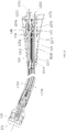
- an electric surgical stapler including a handle 110 and a replaceable working head 120.
- the handle 110 is a driving device for driving the working head 120 to operate, including a hollow handle body 112, a driving motor 113 with an output shaft 1132, and a control unit 114, and the driving motor 113 and the control unit 114 are arranged inside the handle body 112.
- the outer wall of the handle body 112 is provided with an adjustment knob 115.
- the adjustment knob 115 is connected to the output shaft 1132 through a bevel gear system 116.
- the driving motor 113 stops the user may turn the adjustment knob 115, and the bevel gear system 116 may drive the output shaft 1132 to rotate, to achieve manual adjustment.
- the manual mode can be enabled to use the adjustment knob 115 to open the jaw of the working head 120 or finish firing.
- the working head 120 is a circular stapling head, including an anvil 121, cartridge 122, a closing mechanism, a firing mechanism, and a housing 125 accommodating the closing mechanism and the firing mechanism.
- the closing mechanism includes a closing main shaft 1232 and a closing transmission mechanism.
- the closing main shaft 1232 is driven by a driving motor 113 to rotate.
- the closing transmission mechanism is connected to the anvil 121.
- a first linear motion component in the closing transmission mechanism drives the anvil 121 to move in a straight line.
- the first linear motion component includes a first sliding block 1234 and a first push rod 1235 driven by the first sliding block 1234.
- the first sliding block 1234 is connected to the closing main shaft 1232 in a helical transmission form, but the rotation of the first sliding block 1234 is limited.
- the fist sliding block 1234 is able to move in a straight line, and drive the movement of the anvil 121 through the first push rod 1235.
- the firing mechanism includes a firing main shaft 1242 and a firing transmission mechanism.
- the firing main shaft 1242 is driven by the driving motor 113 to rotate.
- the firing transmission mechanism is connected to a staple ejecting plate.
- a second linear motion component in the firing transmission mechanism causes the staple ejecting plate to perform firing actions.
- the second linear motion component is similar to the first linear motion component in the closing transmission mechanism.
- the second linear motion component includes a second sliding block 1244 and a second push rod 1245 driven by the second sliding block 1244.
- the second sliding block 1244 is able to move in a straight line, and drive the movement of the staple ejecting assemblies in the cartridge 122 through the second push rod 1435.
- the working head 120 further includes a firing safety switch 126 mounted on the housing 125.
- the firing safety switch 126 has a first operating position and a second operating position.
- the firing safety switch 126 allows the output shaft 1132 to transmit torque to the closing main shaft 1232 when the firing safety switch 126 is at the first operating position, and the first operating position is defined as a closing position.
- the firing safety switch 126 allows the output shaft 1132 to transmit torque to the firing main shaft 1242 when the firing safety switch 126 is at the second operating position, and the second operating position is defined as a firing position.
- the firing safety switch 126 fits a switching transmission mechanism in the housing 125.
- the switching transmission mechanism includes an input shaft 1271, a switching shaft 1272, a switching driving lever 1273, a first switching ring 1274, a first guide block 1275, a second switching ring 1276 and a second guide block 1277 matching and connected to the output shaft 1132.
- the input shaft 1271 transmits power to the switching shaft 1272 through a gear mechanism.
- the first guide block 1275 is fastened to the input shaft 1271, the first switching ring 1274 is able to drive the closing main shaft 1232 to rotate, and be driven by the switching driving lever 1273 to be engaged with or disengaged from the first guide block 1275.
- the second guide block 1277 is fastened to the firing main shaft 1242, the second switching ring 1276 is able to drive the firing main shaft 1242 to rotate, and be driven by the switching driving lever 1273 to be engaged with or disengaged from the second guide block 1277.
- the firing safety switch 126 may be operated to drive the switching driving lever 1273, so that the first switching ring 1274 is engaged with the first guide block 1275 while the second switching ring 1276 is disengaged from the second guide block 1277, or the first switching ring 1274 is disengaged from the first guide block 1275 while the second switching ring 1276 is engaged with the second guide block 1277. In this way, the switching of the power transmission can be achieved by operating the firing safety switch 126.
- the switching transmission mechanism may be implemented in other forms.
- an intermediate shaft and a switching member matching and connected to the output shaft 1132 may be provided.
- the switching member may make an axially upward movement on the intermediate shaft, the switching member may connect the intermediate shaft to the closing main shaft 1232 at the first operating position, and the switching member may connect the intermediate shaft to the firing main shaft 1242 at the second operating position.
- the handle 110 is only internally provided one driving motor 113 and one output shaft, and can switch power transmission by the firing safety switch 126.
- the firing safety switch 126 is mounted on the housing 125.
- the firing safety switch 126 may also be arranged on the handle body 112, that is, the switching mechanism for power transmission may be arranged within the handle 110.
- the working head 120 also includes a closing limit switch 128 and a pressure sensor 129.
- the closing limit switch 128 is configured to detect the closing stroke of the closing mechanism, and transmit information of the closing stroke to the control unit 114.
- the closing limit switch 128 may be an optoelectronic switch, a micro switch or a proximity switch.
- the closing limit switch 128 is mounted on the housing 125. When the first linear motion component in the closing mechanism moves to a closing position within a preset range, the closing limit switch 128 may be triggered to transmit a signal to the control unit 114, indicating that the closing stroke comes within a preset range.
- the pressure sensor 129 is configured to detect the value of the closing pressure applied on the tissues between the anvil 121 and the cartridge 122 when the closing mechanism performs a closing action, and transmit the value of the closing pressure to the control unit 114.
- the pressure sensor 129 may be arranged on the motion path of the first linear motion component, or may be arranged on the anvil 22 or the cartridge 122.
- the closing mechanism When the driving motor 120 is activated, and the firing safety switch 126 is at the closing position, the closing mechanism operates, the anvil 121 is gradually closed against the cartridge 122.
- the closing main shaft 142 comes within a preset position range (often called a green zone), the closing limit switch 128 is triggered, and transmits information to the control unit 114.
- the control unit 114 also receives the pressure value transmitted from the pressure sensor 129.
- the control unit 114 may call a firing program, and transmits an instruction of controlling the driving motor 113 to drive the firing main shaft 1242. In this way, there is no excessive squeezing or inadequate squeezing, to ensure the tissue is squeezed adequately regardless of the thickness, and to ensure stable effect of the staple formation.
- a closing switch 1123 and an opening switch 1124 connected to the control unit 114 are arranged outside the handle body 112.
- the closing switch 1123 is a common switch for closing and firing, so that the closing switch 1123 is required to be triggered no matter a closing action or a firing action is performed.
- control unit 114 Only when the control unit 114 detects the closing switch 1123 is triggered, and the firing safety switch 126 is at the first operating position, the control unit 114 transmits an instruction of controlling the driving motor 113 to drive the closing main shaft 1232 to move. Thus, when the user operates the electric surgical stapler, the user needs to ensure the firing safety switch 126 is at the first operating position firstly, and then press the closing switch 1123 to start the closing action.
- control unit 114 When the control unit 114 detects the closing switch 1123 is triggered, and the firing safety switch 126 is at the second operating position, the control unit 114 control the driving motor 113 to drive the firing main shaft 1242 to move.
- the closing switch 1123 and the opening switch 1124 can be implemented by Hall switches. If a button with a magnet is arranged outside the handle body 112, the control unit 114 is provided with a Hall switch. The Hall switch may be activated by the magnet. Similarly, the Hall switch may determine whether the switching between the positions of the firing safety switch 126 is detected. The Hall switch may detect the movement of the firing safety switch 126 itself, and may detect the movement of the switching driving lever 1273.
- control unit 114 can detect whether the closing switch 1123, opening switch 1124 or the firing safety switch 126 is triggered, by the arrangement of an optoelectronic switch, a micro switch or a proximity switch.
- the working head 120 also includes a firing limit switch 121A configured to detect the position of the firing main shaft 1242, and transmit information of the position to the control unit 114.
- a firing limit switch 121A detects the firing main shaft 1243 comes within the preset position range, the driving motor 113 stops, and the control unit 114 transmits an instruction of prohibiting the driving motor 113 to drive the closing main shaft 1232 to move. That is, when the firing is completed, the control unit 114 may block the closing switch 1123 to disable the closing switch 1123 until a new working head is replaced.
- the firing limit switch 121A may be an optoelectronic switch, a micro switch or a proximity switch installed on the housing 125.
- the handle 110 is removably connected to the working head 120.
- the handle body 112 fits the housing 125, the handle 110 and the working head 120 are assembled together.
- the housing 125 is removed from the handle body 112, the handle 110 and the working head 120 are separated from each other.
- the working head 120 is a circular stapling head.
- the handle 110 is assembled with the working head 120, the handle 110 is a straight handle along the longitudinal direction of the working head 120, which conforms with the holding habit, to facilitate, for example, the therapy of gastrointestinal diseases.
- the handle body 112 can be connected to or removed from the housing 125 rapidly. If the handle body 112 is provided with an interface part, the housing 125 is provided with a connector accordingly. During assembling, it only needs the housing 125 to be inserted into the handle body 112.
- the end of the output shaft 1132 is provided with an interface, and the end of the input shaft 1271 is inserted into the output shaft 1132, so the input shaft 1271 and the output shaft 1132 can assembled into a whole, while achieving the connection of the dynamical system.
- a data interface 1125 connected to the control unit 114 is arranged inside the handle body 112, configured to connect the closing limit switch 128 and the pressure sensor 129. After the assembly of the handle body 112 and the housing 125, the data connector 1252 of the working head 120 is inserted into the data interface 1125.
- a release button 1126 is arranged outside the handle body 112.
- the release button 1126 has a locking position for locking the housing and a release position for unlocking the housing.
- the release button 1126 When the release button 1126 is pressed, the housing 125 is able to be inserted into the handle body 112. When the pressed release button 1126 is loosened, the housing is locked. When it is required to remove the housing 125, the release button 1126 may be pressed firstly to release locking, and then the housing may be pulled out.
- the housing 125 is also provided with a window to view the motion position of the closing main shaft 1232, to facilitate the user to turn the adjustment knob manually in accordance with specific conditions.
- the adjustment knob 115 is able to supply a manual mode, to deal with the condition of getting stuck.
- the manual mode may be activated to make the driving motor 113 get away from the overload endless loop.
- the anvil 121 and the cartridge 122 may be opened, or continue to finish the firing.
- the electric surgical stapler further includes a replaceable battery pack 117 connected to the handle body 112, and configured to supply power to the driving motor 113.
- the handle body 112 is provided with an indicator light (not shown) connected to the control unit 114.
- the indicator light may show the closing state, the firing state or the battery level of the battery pack.
- the electric surgical stapler according to the present disclosure can detect the closing pressure and the closing stroke simultaneously, to ensure the tissue is squeezed adequately regardless of the thickness of the tissue, to ensure a stable effect of the staple formation.
- the working head is a single-use component.
- the handle 110 removeably fits the working head 120.
- the handle 110 can be used repeatedly after disinfection, to reduce cost. But it is necessary to point out that the above conception of detecting both the closing pressure and the closing stroke is also applicable for an integrated stapler.
- the above working head 120 is a circular stapling head, but can be other types of working heads, for example, a linear stapling head.
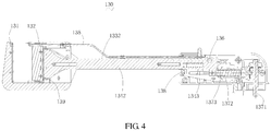
- a linear working head 130 is provided, which is provided with both a closing limit switch and a pressure sensor to detect whether both the closing stroke and closing pressure meet requirements.
- the working head 120 can be replaced with the linear working head 130.
- the linear working head 130 fits the handle 110, and the mechanical connection form is the same as the above embodiment, with a difference that the device is in a shape of a gun after assembling.
- the linear working head 130 includes an anvil 131, a cartridge 132, a closing mechanism, a firing mechanism, and a housing 135 accommodating the closing mechanism and the firing mechanism.
- the closing mechanism includes a closing lever 1332.
- the firing mechanism includes a firing lever 1342.
- the closing lever 1332 and the firing lever 1342 can move in a straight line together, or move in a straight line relative to one another.
- a limit rotation shaft 136 is arranged outside the housing 135.
- the limit rotation shaft 136 can limit both the closing lever 1332 and the firing lever 1342 in the axial direction, to allow the closing lever 1332 and the firing lever 1342 to move together.
- the limit rotation shaft 136 rotates so that the limit rotation shaft 136 is separated from the firing lever 1342 in the axial direction, the firing lever 1342 can move in a straight line relative to the closing lever 1332.
- a transmission mechanism is arranged outside the housing 135, including a input shaft 1371, a thread bushing 1372 that is rotatable when driven by tapered teeth, and a screw 1373 in a threaded connection with the thread bushing 1372, and the rotation of the screw 1373 is limited so that the screw 1373 only makes axial movement.
- a flat fitting portion may be arranged between the screw 1373 and the thread bushing 1372, so that the screw 1373 may only translate in the axial direction.
- the screw 1373 is connected to the firing lever 1342 to drive the firing lever 1342 to move in a straight line.
- the limit rotation shaft 136 is equivalent to a firing safety switch which must be operated to switch the closing lever 1332 and the firing lever 1342.
- a closing limit switch 138 is arranged inside the housing 135.
- the firing lever 1342 may drive the closing lever 1332 to move together, and when firing lever 1342 moves to a specified position, the raised portion 1343 on the firing lever 1342 trigger the closing limit switch 138.
- the limit rotation shaft 136 is operated to separate the closing lever 1332 from the firing lever 134, the firing lever 134 does not drive the closing lever 1332 when moving, and the raised portion 1343 moves and triggers the closing limit switch 138 again, to finish the firing of the cartridge.
- the pressure sensor 139 is arranged on the cartridge 132. Specifically, the pressure sensor 139 may be arranged between the staple ejecting assembly of the anvil 132 and the firing lever 1342. During closing, the firing lever 1342 drives the closing lever 1332 to push the staple ejecting assembly to drive the cartridge 132 to move. Thus the pressure sensor 139 can acquire the closing pressure, can transmit the closing pressure to the control unit 114. During firing, in addition to the staple ejecting assembly, the cartridge 132 is limited in the axial direction, and the firing lever 1342 continues to push the staple ejecting assembly, so that the staple ejecting assembly moves forward relative to the cartridge 132 to finish the firing. Alternatively, the pressure sensor 139 may be arranged on the motion path of the closing lever 1332.
- the linear working head 130 fits the handle 110, and is able to detect both the closing pressure and the closing stroke, to ensure the tissue is squeezed adequately regardless of the thickness, and to ensure stable effect of the staple formation.
Landscapes
- Health & Medical Sciences (AREA)
- Life Sciences & Earth Sciences (AREA)
- Surgery (AREA)
- Molecular Biology (AREA)
- Engineering & Computer Science (AREA)
- Biomedical Technology (AREA)
- Heart & Thoracic Surgery (AREA)
- Medical Informatics (AREA)
- Nuclear Medicine, Radiotherapy & Molecular Imaging (AREA)
- Animal Behavior & Ethology (AREA)
- General Health & Medical Sciences (AREA)
- Public Health (AREA)
- Veterinary Medicine (AREA)
- Physiology (AREA)
- Surgical Instruments (AREA)
- Portable Nailing Machines And Staplers (AREA)
Priority Applications (2)
| Application Number | Priority Date | Filing Date | Title |
|---|---|---|---|
| RS20210515A RS61769B1 (sr) | 2015-12-22 | 2016-07-29 | Električna heftalica |
| PL16877300T PL3395263T3 (pl) | 2015-12-22 | 2016-07-29 | Stapler elektryczny |
Applications Claiming Priority (2)
| Application Number | Priority Date | Filing Date | Title |
|---|---|---|---|
| CN201510974054.2A CN105395232B (zh) | 2015-12-22 | 2015-12-22 | 电动吻合器 |
| PCT/CN2016/092393 WO2017107488A1 (fr) | 2015-12-22 | 2016-07-29 | Agrafeuse électrique |
Publications (3)
| Publication Number | Publication Date |
|---|---|
| EP3395263A1 true EP3395263A1 (fr) | 2018-10-31 |
| EP3395263A4 EP3395263A4 (fr) | 2019-08-07 |
| EP3395263B1 EP3395263B1 (fr) | 2021-03-24 |
Family
ID=55461244
Family Applications (1)
| Application Number | Title | Priority Date | Filing Date |
|---|---|---|---|
| EP16877300.0A Active EP3395263B1 (fr) | 2015-12-22 | 2016-07-29 | Agrafeuse électrique |
Country Status (9)
| Country | Link |
|---|---|
| US (1) | US10743879B2 (fr) |
| EP (1) | EP3395263B1 (fr) |
| CN (1) | CN105395232B (fr) |
| ES (1) | ES2866600T3 (fr) |
| HU (1) | HUE054043T2 (fr) |
| PL (1) | PL3395263T3 (fr) |
| PT (1) | PT3395263T (fr) |
| RS (1) | RS61769B1 (fr) |
| WO (1) | WO2017107488A1 (fr) |
Cited By (1)
| Publication number | Priority date | Publication date | Assignee | Title |
|---|---|---|---|---|
| CN116609627A (zh) * | 2023-06-15 | 2023-08-18 | 国网江苏省电力有限公司电力科学研究院 | 一种基于压力监测的局部放电检测装置及方法 |
Families Citing this family (31)
| Publication number | Priority date | Publication date | Assignee | Title |
|---|---|---|---|---|
| CN105395232B (zh) | 2015-12-22 | 2019-02-15 | 苏州英途康医疗科技有限公司 | 电动吻合器 |
| CN106333720B (zh) * | 2016-10-14 | 2019-02-15 | 苏州英途康医疗科技有限公司 | 智能腔镜吻合器 |
| KR101838188B1 (ko) * | 2016-10-31 | 2018-03-13 | 비앤알(주) | 원형 문합기 |
| US11027105B2 (en) * | 2017-07-13 | 2021-06-08 | Biosense Webster (Israel) Ltd. | Adjustable instrument for dilation of anatomical passageway |
| CN107485420A (zh) * | 2017-09-15 | 2017-12-19 | 山东省立医院 | 一种带压力传感器的吻合器 |
| CN209107460U (zh) * | 2017-12-20 | 2019-07-16 | 西人马(厦门)科技有限公司 | 智能吻合器 |
| CN108113725B (zh) * | 2017-12-21 | 2020-07-28 | 苏州英途康医疗科技有限公司 | 吻合器控制方法及吻合器 |
| CN107928739A (zh) * | 2017-12-21 | 2018-04-20 | 苏州英途康医疗科技有限公司 | 痔疮吻合器 |
| CN109620326B (zh) * | 2018-12-15 | 2024-05-24 | 华融科创生物科技(天津)有限公司 | 医用血管吻合器 |
| CN111466985A (zh) * | 2019-01-24 | 2020-07-31 | 苏州英途康医疗科技有限公司 | 吻合器手柄系统及吻合器 |
| CN111466984B (zh) * | 2019-01-24 | 2021-09-03 | 苏州英途康医疗科技有限公司 | 吻合器手柄系统及吻合器 |
| CN111466983B (zh) * | 2019-01-24 | 2021-05-14 | 苏州英途康医疗科技有限公司 | 吻合器手柄系统及吻合器 |
| CN112690861B (zh) * | 2019-10-23 | 2023-01-20 | 苏州英途康医疗科技有限公司 | 医疗器械、工作头及送夹位置识别方法 |
| WO2021128088A1 (fr) * | 2019-12-25 | 2021-07-01 | 北京博辉瑞进生物科技有限公司 | Agrafeuse chirurgicale à entraînement intelligent |
| CN113884917A (zh) * | 2020-07-03 | 2022-01-04 | 苏州英途康医疗科技有限公司 | 电动吻合器及其电池电量检测方法、装置及存储介质 |
| CN111772705B (zh) * | 2020-08-07 | 2025-06-27 | 山东威瑞外科医用制品有限公司 | 一种电动吻合器 |
| CN114176689B (zh) * | 2020-09-14 | 2024-04-19 | 苏州英途康医疗科技有限公司 | 电动吻合器及其驱动机构的定位方法、装置及存储介质 |
| US11877897B2 (en) | 2020-10-02 | 2024-01-23 | Cilag Gmbh International | Situational awareness of instruments location and individualization of users to control displays |
| US11748924B2 (en) | 2020-10-02 | 2023-09-05 | Cilag Gmbh International | Tiered system display control based on capacity and user operation |
| US12016566B2 (en) | 2020-10-02 | 2024-06-25 | Cilag Gmbh International | Surgical instrument with adaptive function controls |
| US12580072B2 (en) | 2020-10-02 | 2026-03-17 | Cilag Gmbh International | Cloud analytics packages |
| US12064293B2 (en) | 2020-10-02 | 2024-08-20 | Cilag Gmbh International | Field programmable surgical visualization system |
| US11963683B2 (en) | 2020-10-02 | 2024-04-23 | Cilag Gmbh International | Method for operating tiered operation modes in a surgical system |
| US12484897B2 (en) | 2020-10-02 | 2025-12-02 | Cilag Gmbh International | Surgical instrument with adaptive configuration control |
| US20220104820A1 (en) * | 2020-10-02 | 2022-04-07 | Ethicon Llc | Surgical instrument with adaptive motor control |
| US12213801B2 (en) | 2020-10-02 | 2025-02-04 | Cilag Gmbh International | Surgical visualization and particle trend analysis system |
| US12472032B2 (en) | 2020-10-02 | 2025-11-18 | Cilag Gmbh International | Monitoring of user visual gaze to control which display system displays the primary information |
| CN112826553B (zh) * | 2021-01-22 | 2025-07-04 | 北京天助畅运医疗技术股份有限公司 | 一种组织识别模块和腔镜吻合器 |
| CN113367754B (zh) * | 2021-07-10 | 2024-01-16 | 江苏康赛医疗器械科技有限公司 | 一种具有保险组件的直线切割吻合器 |
| CN113456153B (zh) * | 2021-07-11 | 2024-01-16 | 江苏康赛医疗器械科技有限公司 | 一种行程精确可控的肛肠套扎吻合器 |
| CN115089246B (zh) * | 2022-06-27 | 2025-03-04 | 宝玛医疗科技(无锡)有限公司 | 防止误击发的电动吻合器 |
Family Cites Families (21)
| Publication number | Priority date | Publication date | Assignee | Title |
|---|---|---|---|---|
| US7559452B2 (en) * | 2005-02-18 | 2009-07-14 | Ethicon Endo-Surgery, Inc. | Surgical instrument having fluid actuated opposing jaws |
| US8038046B2 (en) * | 2006-05-19 | 2011-10-18 | Ethicon Endo-Surgery, Inc. | Electrical surgical instrument with optimized power supply and drive |
| US9861359B2 (en) | 2006-01-31 | 2018-01-09 | Ethicon Llc | Powered surgical instruments with firing system lockout arrangements |
| US20110174861A1 (en) | 2007-01-10 | 2011-07-21 | Shelton Iv Frederick E | Surgical Instrument With Wireless Communication Between Control Unit and Remote Sensor |
| CN101467907A (zh) * | 2007-12-28 | 2009-07-01 | 苏州天臣国际医疗科技有限公司 | 传感式外科装订器械 |
| CN102247182A (zh) * | 2011-04-29 | 2011-11-23 | 常州市康迪医用吻合器有限公司 | 外科用电动吻合器 |
| US9038882B2 (en) * | 2012-02-03 | 2015-05-26 | Covidien Lp | Circular stapling instrument |
| CN103784175B (zh) * | 2012-11-26 | 2015-09-16 | 天津瑞贝精密机械技术研发有限公司 | 电动吻合器 |
| CN103110439B (zh) * | 2013-01-29 | 2016-06-01 | 北京派尔特医疗科技股份有限公司 | 电动外科装订器械的控制方法与控制装置 |
| US9801626B2 (en) * | 2013-04-16 | 2017-10-31 | Ethicon Llc | Modular motor driven surgical instruments with alignment features for aligning rotary drive shafts with surgical end effector shafts |
| CN103405254B (zh) * | 2013-04-23 | 2016-06-29 | 北京中法派尔特医疗设备有限公司 | 电动外科装订器械的控制方法与控制装置 |
| CN103405257B (zh) * | 2013-04-23 | 2016-06-22 | 北京中法派尔特医疗设备有限公司 | 电动外科装订器械的控制方法与控制装置 |
| CN203468671U (zh) * | 2013-08-09 | 2014-03-12 | 瑞奇外科器械(中国)有限公司 | 双向行程控制开关、弯转行程控制装置和外科手术器械 |
| US9833235B2 (en) * | 2013-08-16 | 2017-12-05 | Covidien Lp | Chip assembly for reusable surgical instruments |
| CN204092074U (zh) * | 2014-09-05 | 2015-01-14 | 瑞奇外科器械(中国)有限公司 | 外科手术器械的驱动装置及外科手术器械 |
| CN104367361B (zh) * | 2014-11-14 | 2017-01-25 | 常州海尔斯医疗器械科技有限公司 | 一次性使用消化道智能吻合器及其使用方法 |
| US10226250B2 (en) | 2015-02-27 | 2019-03-12 | Ethicon Llc | Modular stapling assembly |
| CN105395232B (zh) * | 2015-12-22 | 2019-02-15 | 苏州英途康医疗科技有限公司 | 电动吻合器 |
| CN105411641B (zh) | 2015-12-22 | 2018-07-06 | 苏州英途康医疗科技有限公司 | 吻合器 |
| CN105596046B (zh) * | 2015-12-22 | 2018-05-08 | 苏州英途康医疗科技有限公司 | 吻合器 |
| CN105411642B (zh) | 2015-12-22 | 2018-09-11 | 苏州英途康医疗科技有限公司 | 电动吻合器及其闭合、击发控制方法 |
-
2015
- 2015-12-22 CN CN201510974054.2A patent/CN105395232B/zh active Active
-
2016
- 2016-07-29 ES ES16877300T patent/ES2866600T3/es active Active
- 2016-07-29 US US15/567,153 patent/US10743879B2/en active Active
- 2016-07-29 PL PL16877300T patent/PL3395263T3/pl unknown
- 2016-07-29 WO PCT/CN2016/092393 patent/WO2017107488A1/fr not_active Ceased
- 2016-07-29 HU HUE16877300A patent/HUE054043T2/hu unknown
- 2016-07-29 EP EP16877300.0A patent/EP3395263B1/fr active Active
- 2016-07-29 RS RS20210515A patent/RS61769B1/sr unknown
- 2016-07-29 PT PT168773000T patent/PT3395263T/pt unknown
Cited By (2)
| Publication number | Priority date | Publication date | Assignee | Title |
|---|---|---|---|---|
| CN116609627A (zh) * | 2023-06-15 | 2023-08-18 | 国网江苏省电力有限公司电力科学研究院 | 一种基于压力监测的局部放电检测装置及方法 |
| CN116609627B (zh) * | 2023-06-15 | 2024-03-08 | 国网江苏省电力有限公司电力科学研究院 | 一种基于压力监测的局部放电检测装置及方法 |
Also Published As
| Publication number | Publication date |
|---|---|
| HUE054043T2 (hu) | 2021-08-30 |
| PT3395263T (pt) | 2021-04-15 |
| ES2866600T3 (es) | 2021-10-19 |
| EP3395263B1 (fr) | 2021-03-24 |
| CN105395232A (zh) | 2016-03-16 |
| US20180098768A1 (en) | 2018-04-12 |
| CN105395232B (zh) | 2019-02-15 |
| WO2017107488A1 (fr) | 2017-06-29 |
| RS61769B1 (sr) | 2021-05-31 |
| PL3395263T3 (pl) | 2021-09-06 |
| EP3395263A4 (fr) | 2019-08-07 |
| US10743879B2 (en) | 2020-08-18 |
Similar Documents
| Publication | Publication Date | Title |
|---|---|---|
| US10743879B2 (en) | Electric surgical stapler | |
| US10595865B2 (en) | Electric surgical stapler | |
| US10695056B2 (en) | Electric surgical stapler | |
| JP5253823B2 (ja) | インターロックおよびインターロックを含む外科器具 | |
| US7431188B1 (en) | Surgical stapling apparatus with powered articulation | |
| JP5415704B2 (ja) | 動力アーティキュレーションを備える手術用ステープリング装置 | |
| KR101369231B1 (ko) | 피드백 시스템을 갖는 수술장비 | |
| RU2594070C2 (ru) | Доступ к данным, хранимым в памяти хирургического инструмента | |
| CN102368958B (zh) | 动力手术缝合器 | |
| CN106821441B (zh) | 一种电动吻合器及其击发回退控制方法 | |
| CN104257409B (zh) | 吻合器 | |
| CN108113725B (zh) | 吻合器控制方法及吻合器 | |
| CN108135597A (zh) | 具有可选择性地脱离接合的螺纹驱动系统的外科器械 | |
| CN102368957A (zh) | 动力手术缝合器的改进 | |
| CN105411641A (zh) | 吻合器 | |
| JP7490284B2 (ja) | 電動吻合器及びその制御方法 | |
| CN204379345U (zh) | 具有微调机构的吻合器 | |
| CN116549041A (zh) | 外科器械 | |
| CN104306039B (zh) | 吻合器 | |
| CN108135598A (zh) | 具有渐进式旋转驱动系统的外科器械 | |
| CN204181676U (zh) | 吻合器 | |
| AU2013224742B2 (en) | Surgical stapling apparatus with powered articulation |
Legal Events
| Date | Code | Title | Description |
|---|---|---|---|
| STAA | Information on the status of an ep patent application or granted ep patent |
Free format text: STATUS: THE INTERNATIONAL PUBLICATION HAS BEEN MADE |
|
| PUAI | Public reference made under article 153(3) epc to a published international application that has entered the european phase |
Free format text: ORIGINAL CODE: 0009012 |
|
| STAA | Information on the status of an ep patent application or granted ep patent |
Free format text: STATUS: REQUEST FOR EXAMINATION WAS MADE |
|
| 17P | Request for examination filed |
Effective date: 20171016 |
|
| AK | Designated contracting states |
Kind code of ref document: A1 Designated state(s): AL AT BE BG CH CY CZ DE DK EE ES FI FR GB GR HR HU IE IS IT LI LT LU LV MC MK MT NL NO PL PT RO RS SE SI SK SM TR |
|
| AX | Request for extension of the european patent |
Extension state: BA ME |
|
| DAV | Request for validation of the european patent (deleted) | ||
| DAX | Request for extension of the european patent (deleted) | ||
| A4 | Supplementary search report drawn up and despatched |
Effective date: 20190710 |
|
| RIC1 | Information provided on ipc code assigned before grant |
Ipc: A61B 17/115 20060101AFI20190704BHEP Ipc: A61B 17/00 20060101ALI20190704BHEP Ipc: A61B 17/072 20060101ALI20190704BHEP Ipc: A61B 90/00 20160101ALI20190704BHEP |
|
| GRAP | Despatch of communication of intention to grant a patent |
Free format text: ORIGINAL CODE: EPIDOSNIGR1 |
|
| STAA | Information on the status of an ep patent application or granted ep patent |
Free format text: STATUS: GRANT OF PATENT IS INTENDED |
|
| INTG | Intention to grant announced |
Effective date: 20201020 |
|
| GRAS | Grant fee paid |
Free format text: ORIGINAL CODE: EPIDOSNIGR3 |
|
| GRAA | (expected) grant |
Free format text: ORIGINAL CODE: 0009210 |
|
| STAA | Information on the status of an ep patent application or granted ep patent |
Free format text: STATUS: THE PATENT HAS BEEN GRANTED |
|
| AK | Designated contracting states |
Kind code of ref document: B1 Designated state(s): AL AT BE BG CH CY CZ DE DK EE ES FI FR GB GR HR HU IE IS IT LI LT LU LV MC MK MT NL NO PL PT RO RS SE SI SK SM TR |
|
| REG | Reference to a national code |
Ref country code: GB Ref legal event code: FG4D |
|
| REG | Reference to a national code |
Ref country code: CH Ref legal event code: EP Ref country code: CH Ref legal event code: NV Representative=s name: COSMOVICI INTELLECTUAL PROPERTY SARL, CH |
|
| REG | Reference to a national code |
Ref country code: NL Ref legal event code: FP Ref country code: IE Ref legal event code: FG4D |
|
| REG | Reference to a national code |
Ref country code: DE Ref legal event code: R096 Ref document number: 602016055021 Country of ref document: DE Ref country code: AT Ref legal event code: REF Ref document number: 1373670 Country of ref document: AT Kind code of ref document: T Effective date: 20210415 Ref country code: PT Ref legal event code: SC4A Ref document number: 3395263 Country of ref document: PT Date of ref document: 20210415 Kind code of ref document: T Free format text: AVAILABILITY OF NATIONAL TRANSLATION Effective date: 20210409 |
|
| REG | Reference to a national code |
Ref country code: SK Ref legal event code: T3 Ref document number: E 36929 Country of ref document: SK |
|
| REG | Reference to a national code |
Ref country code: LT Ref legal event code: MG9D |
|
| PG25 | Lapsed in a contracting state [announced via postgrant information from national office to epo] |
Ref country code: NO Free format text: LAPSE BECAUSE OF FAILURE TO SUBMIT A TRANSLATION OF THE DESCRIPTION OR TO PAY THE FEE WITHIN THE PRESCRIBED TIME-LIMIT Effective date: 20210624 Ref country code: HR Free format text: LAPSE BECAUSE OF FAILURE TO SUBMIT A TRANSLATION OF THE DESCRIPTION OR TO PAY THE FEE WITHIN THE PRESCRIBED TIME-LIMIT Effective date: 20210324 Ref country code: FI Free format text: LAPSE BECAUSE OF FAILURE TO SUBMIT A TRANSLATION OF THE DESCRIPTION OR TO PAY THE FEE WITHIN THE PRESCRIBED TIME-LIMIT Effective date: 20210324 Ref country code: GR Free format text: LAPSE BECAUSE OF FAILURE TO SUBMIT A TRANSLATION OF THE DESCRIPTION OR TO PAY THE FEE WITHIN THE PRESCRIBED TIME-LIMIT Effective date: 20210625 Ref country code: BG Free format text: LAPSE BECAUSE OF FAILURE TO SUBMIT A TRANSLATION OF THE DESCRIPTION OR TO PAY THE FEE WITHIN THE PRESCRIBED TIME-LIMIT Effective date: 20210624 |
|
| REG | Reference to a national code |
Ref country code: HU Ref legal event code: AG4A Ref document number: E054043 Country of ref document: HU |
|
| PG25 | Lapsed in a contracting state [announced via postgrant information from national office to epo] |
Ref country code: SE Free format text: LAPSE BECAUSE OF FAILURE TO SUBMIT A TRANSLATION OF THE DESCRIPTION OR TO PAY THE FEE WITHIN THE PRESCRIBED TIME-LIMIT Effective date: 20210324 Ref country code: LV Free format text: LAPSE BECAUSE OF FAILURE TO SUBMIT A TRANSLATION OF THE DESCRIPTION OR TO PAY THE FEE WITHIN THE PRESCRIBED TIME-LIMIT Effective date: 20210324 |
|
| REG | Reference to a national code |
Ref country code: ES Ref legal event code: FG2A Ref document number: 2866600 Country of ref document: ES Kind code of ref document: T3 Effective date: 20211019 |
|
| PG25 | Lapsed in a contracting state [announced via postgrant information from national office to epo] |
Ref country code: SM Free format text: LAPSE BECAUSE OF FAILURE TO SUBMIT A TRANSLATION OF THE DESCRIPTION OR TO PAY THE FEE WITHIN THE PRESCRIBED TIME-LIMIT Effective date: 20210324 Ref country code: EE Free format text: LAPSE BECAUSE OF FAILURE TO SUBMIT A TRANSLATION OF THE DESCRIPTION OR TO PAY THE FEE WITHIN THE PRESCRIBED TIME-LIMIT Effective date: 20210324 Ref country code: LT Free format text: LAPSE BECAUSE OF FAILURE TO SUBMIT A TRANSLATION OF THE DESCRIPTION OR TO PAY THE FEE WITHIN THE PRESCRIBED TIME-LIMIT Effective date: 20210324 |
|
| PG25 | Lapsed in a contracting state [announced via postgrant information from national office to epo] |
Ref country code: RO Free format text: LAPSE BECAUSE OF FAILURE TO SUBMIT A TRANSLATION OF THE DESCRIPTION OR TO PAY THE FEE WITHIN THE PRESCRIBED TIME-LIMIT Effective date: 20210324 Ref country code: IS Free format text: LAPSE BECAUSE OF FAILURE TO SUBMIT A TRANSLATION OF THE DESCRIPTION OR TO PAY THE FEE WITHIN THE PRESCRIBED TIME-LIMIT Effective date: 20210724 |
|
| REG | Reference to a national code |
Ref country code: DE Ref legal event code: R097 Ref document number: 602016055021 Country of ref document: DE |
|
| PG25 | Lapsed in a contracting state [announced via postgrant information from national office to epo] |
Ref country code: DK Free format text: LAPSE BECAUSE OF FAILURE TO SUBMIT A TRANSLATION OF THE DESCRIPTION OR TO PAY THE FEE WITHIN THE PRESCRIBED TIME-LIMIT Effective date: 20210324 Ref country code: AL Free format text: LAPSE BECAUSE OF FAILURE TO SUBMIT A TRANSLATION OF THE DESCRIPTION OR TO PAY THE FEE WITHIN THE PRESCRIBED TIME-LIMIT Effective date: 20210324 |
|
| PLBE | No opposition filed within time limit |
Free format text: ORIGINAL CODE: 0009261 |
|
| STAA | Information on the status of an ep patent application or granted ep patent |
Free format text: STATUS: NO OPPOSITION FILED WITHIN TIME LIMIT |
|
| PG25 | Lapsed in a contracting state [announced via postgrant information from national office to epo] |
Ref country code: SI Free format text: LAPSE BECAUSE OF FAILURE TO SUBMIT A TRANSLATION OF THE DESCRIPTION OR TO PAY THE FEE WITHIN THE PRESCRIBED TIME-LIMIT Effective date: 20210324 |
|
| 26N | No opposition filed |
Effective date: 20220104 |
|
| PG25 | Lapsed in a contracting state [announced via postgrant information from national office to epo] |
Ref country code: MC Free format text: LAPSE BECAUSE OF FAILURE TO SUBMIT A TRANSLATION OF THE DESCRIPTION OR TO PAY THE FEE WITHIN THE PRESCRIBED TIME-LIMIT Effective date: 20210324 |
|
| PG25 | Lapsed in a contracting state [announced via postgrant information from national office to epo] |
Ref country code: IS Free format text: LAPSE BECAUSE OF FAILURE TO SUBMIT A TRANSLATION OF THE DESCRIPTION OR TO PAY THE FEE WITHIN THE PRESCRIBED TIME-LIMIT Effective date: 20210724 |
|
| PG25 | Lapsed in a contracting state [announced via postgrant information from national office to epo] |
Ref country code: IE Free format text: LAPSE BECAUSE OF NON-PAYMENT OF DUE FEES Effective date: 20210729 |
|
| PG25 | Lapsed in a contracting state [announced via postgrant information from national office to epo] |
Ref country code: CY Free format text: LAPSE BECAUSE OF FAILURE TO SUBMIT A TRANSLATION OF THE DESCRIPTION OR TO PAY THE FEE WITHIN THE PRESCRIBED TIME-LIMIT Effective date: 20210324 |
|
| PG25 | Lapsed in a contracting state [announced via postgrant information from national office to epo] |
Ref country code: MK Free format text: LAPSE BECAUSE OF FAILURE TO SUBMIT A TRANSLATION OF THE DESCRIPTION OR TO PAY THE FEE WITHIN THE PRESCRIBED TIME-LIMIT Effective date: 20210324 |
|
| PG25 | Lapsed in a contracting state [announced via postgrant information from national office to epo] |
Ref country code: TR Free format text: LAPSE BECAUSE OF FAILURE TO SUBMIT A TRANSLATION OF THE DESCRIPTION OR TO PAY THE FEE WITHIN THE PRESCRIBED TIME-LIMIT Effective date: 20210324 |
|
| PG25 | Lapsed in a contracting state [announced via postgrant information from national office to epo] |
Ref country code: MT Free format text: LAPSE BECAUSE OF FAILURE TO SUBMIT A TRANSLATION OF THE DESCRIPTION OR TO PAY THE FEE WITHIN THE PRESCRIBED TIME-LIMIT Effective date: 20210324 |
|
| PGFP | Annual fee paid to national office [announced via postgrant information from national office to epo] |
Ref country code: RS Payment date: 20250619 Year of fee payment: 10 |
|
| PGFP | Annual fee paid to national office [announced via postgrant information from national office to epo] |
Ref country code: NL Payment date: 20250630 Year of fee payment: 10 Ref country code: LU Payment date: 20250630 Year of fee payment: 10 |
|
| PGFP | Annual fee paid to national office [announced via postgrant information from national office to epo] |
Ref country code: PT Payment date: 20250620 Year of fee payment: 10 |
|
| PGFP | Annual fee paid to national office [announced via postgrant information from national office to epo] |
Ref country code: SK Payment date: 20250620 Year of fee payment: 10 |
|
| PGFP | Annual fee paid to national office [announced via postgrant information from national office to epo] |
Ref country code: HU Payment date: 20250627 Year of fee payment: 10 |
|
| PGFP | Annual fee paid to national office [announced via postgrant information from national office to epo] |
Ref country code: ES Payment date: 20250811 Year of fee payment: 10 |
|
| PGFP | Annual fee paid to national office [announced via postgrant information from national office to epo] |
Ref country code: DE Payment date: 20250711 Year of fee payment: 10 |
|
| PGFP | Annual fee paid to national office [announced via postgrant information from national office to epo] |
Ref country code: IT Payment date: 20250708 Year of fee payment: 10 Ref country code: PL Payment date: 20250619 Year of fee payment: 10 |
|
| PGFP | Annual fee paid to national office [announced via postgrant information from national office to epo] |
Ref country code: BE Payment date: 20250724 Year of fee payment: 10 Ref country code: GB Payment date: 20250723 Year of fee payment: 10 |
|
| PGFP | Annual fee paid to national office [announced via postgrant information from national office to epo] |
Ref country code: AT Payment date: 20250626 Year of fee payment: 10 Ref country code: FR Payment date: 20250730 Year of fee payment: 10 |
|
| PGFP | Annual fee paid to national office [announced via postgrant information from national office to epo] |
Ref country code: CH Payment date: 20250801 Year of fee payment: 10 |
|
| PGFP | Annual fee paid to national office [announced via postgrant information from national office to epo] |
Ref country code: CZ Payment date: 20250729 Year of fee payment: 10 |