EP3395314B1 - Verkleidungsschutzeinheiten für teleskopsäulen und verstellbare stützvorrichtungen - Google Patents
Verkleidungsschutzeinheiten für teleskopsäulen und verstellbare stützvorrichtungen Download PDFInfo
- Publication number
- EP3395314B1 EP3395314B1 EP18169373.0A EP18169373A EP3395314B1 EP 3395314 B1 EP3395314 B1 EP 3395314B1 EP 18169373 A EP18169373 A EP 18169373A EP 3395314 B1 EP3395314 B1 EP 3395314B1
- Authority
- EP
- European Patent Office
- Prior art keywords
- cassette
- protection unit
- column
- cladding protection
- coupled
- Prior art date
- Legal status (The legal status is an assumption and is not a legal conclusion. Google has not performed a legal analysis and makes no representation as to the accuracy of the status listed.)
- Active
Links
Images



Classifications
-
- A—HUMAN NECESSITIES
- A61—MEDICAL OR VETERINARY SCIENCE; HYGIENE
- A61G—TRANSPORT, PERSONAL CONVEYANCES, OR ACCOMMODATION SPECIALLY ADAPTED FOR PATIENTS OR DISABLED PERSONS; OPERATING TABLES OR CHAIRS; CHAIRS FOR DENTISTRY; FUNERAL DEVICES
- A61G13/00—Operating tables; Auxiliary appliances therefor
- A61G13/10—Parts, details or accessories
-
- A—HUMAN NECESSITIES
- A61—MEDICAL OR VETERINARY SCIENCE; HYGIENE
- A61G—TRANSPORT, PERSONAL CONVEYANCES, OR ACCOMMODATION SPECIALLY ADAPTED FOR PATIENTS OR DISABLED PERSONS; OPERATING TABLES OR CHAIRS; CHAIRS FOR DENTISTRY; FUNERAL DEVICES
- A61G13/00—Operating tables; Auxiliary appliances therefor
- A61G13/02—Adjustable operating tables; Controls therefor
- A61G13/06—Adjustable operating tables; Controls therefor raising or lowering of the whole table surface
-
- F—MECHANICAL ENGINEERING; LIGHTING; HEATING; WEAPONS; BLASTING
- F16—ENGINEERING ELEMENTS AND UNITS; GENERAL MEASURES FOR PRODUCING AND MAINTAINING EFFECTIVE FUNCTIONING OF MACHINES OR INSTALLATIONS; THERMAL INSULATION IN GENERAL
- F16B—DEVICES FOR FASTENING OR SECURING CONSTRUCTIONAL ELEMENTS OR MACHINE PARTS TOGETHER, e.g. NAILS, BOLTS, CIRCLIPS, CLAMPS, CLIPS OR WEDGES; JOINTS OR JOINTING
- F16B1/00—Devices for securing together, or preventing relative movement between, constructional elements or machine parts
-
- A—HUMAN NECESSITIES
- A61—MEDICAL OR VETERINARY SCIENCE; HYGIENE
- A61G—TRANSPORT, PERSONAL CONVEYANCES, OR ACCOMMODATION SPECIALLY ADAPTED FOR PATIENTS OR DISABLED PERSONS; OPERATING TABLES OR CHAIRS; CHAIRS FOR DENTISTRY; FUNERAL DEVICES
- A61G2203/00—General characteristics of devices
- A61G2203/70—General characteristics of devices with special adaptations, e.g. for safety or comfort
- A61G2203/72—General characteristics of devices with special adaptations, e.g. for safety or comfort for collision prevention
-
- F—MECHANICAL ENGINEERING; LIGHTING; HEATING; WEAPONS; BLASTING
- F16—ENGINEERING ELEMENTS AND UNITS; GENERAL MEASURES FOR PRODUCING AND MAINTAINING EFFECTIVE FUNCTIONING OF MACHINES OR INSTALLATIONS; THERMAL INSULATION IN GENERAL
- F16B—DEVICES FOR FASTENING OR SECURING CONSTRUCTIONAL ELEMENTS OR MACHINE PARTS TOGETHER, e.g. NAILS, BOLTS, CIRCLIPS, CLAMPS, CLIPS OR WEDGES; JOINTS OR JOINTING
- F16B2200/00—Constructional details of connections not covered for in other groups of this subclass
- F16B2200/83—Use of a magnetic material
Definitions
- the present specification generally relates to cladding protection units, and, more specifically, to cladding protection units for telescoping columns and adjustable support apparatuses.
- Adjustable support apparatuses such as those for supporting a patient may include an adjustable column to facilitate adjusting the height or orientation of the adjustable support apparatus.
- placing items beneath the adjustable support apparatus may hinder the adjustability of the adjustable support apparatus and/or cause damage to the cladding of the adjustable column.
- Document US2015335512 discloses a shroud guard for protecting a height adjustment mechanism used to raise and lower height of an operating room table, having a shield that is removably secured to an upstanding shield support and extending transversely over a table base of the room table.
- a cladding protection unit for a column of an adjustable support apparatus includes a frame including a first portion configured to be magnetically coupled to a second portion so as to extend around a perimeter of the column.
- Each of the first portion and the second portion include a sidewall, the sidewall of the first portion of the frame and the sidewall of the second portion of the frame forming a column receiving space when the first portion is magnetically coupled to the second portion, and a standoff flange extending outward from the sidewall.
- the cladding protection unit further includes one or more magnets coupled to at least one of the first portion and the second portion of the frame to magnetically couple the first portion to the second portion, wherein, when the cladding protection unit is positioned around a perimeter of the column of the adjustable support apparatus, the column is positioned in the column receiving space of the frame and the standoff flange of the frame extends outward from a perimeter of the column.
- a telescoping column assembly in another embodiment, includes a telescoping column and a cladding protection unit encircling a perimeter of the telescoping column.
- the telescoping column includes a plurality of nestable cassettes.
- the plurality of nestable cassettes include a base cassette, at least one intermediate cassette coupled to the base cassette, and a master cassette coupled to the at least one intermediate cassette.
- a projected perimeter of the master cassette circumscribes a perimeter of the at least one intermediate cassette and a projected perimeter of the at one least intermediate cassette circumscribes a perimeter of the base cassette such that the base cassette is nestable within the at least one intermediate cassette and the at least one intermediate cassette is nestable within the master cassette.
- the cladding protection unit includes a sidewall forming a column receiving space and a standoff flange extending from the sidewall away from the column receiving space. A projected perimeter of the standoff flange circumscribes the perimeter of the master cassette.
- an adjustable support apparatus in yet another embodiment, includes a base, a table top assembly, a telescoping column positioned on the base and supporting the table top assembly on the base, and a cladding protection unit positioned on the base and encircling a perimeter of the telescoping column.
- the telescoping column includes a plurality of nestable cassettes.
- the plurality of nestable cassettes include a base cassette supported on the base, at least one intermediate cassette coupled to the base cassette, and a master cassette coupled to the table top assembly and the at least one intermediate cassette.
- a projected perimeter of the master cassette circumscribes a perimeter of the at least one intermediate cassette and a projected perimeter of the at one least intermediate cassette circumscribes a perimeter of the base cassette such that the base cassette is nestable within the at least one intermediate cassette and the at least one intermediate cassette is nestable within the master cassette.
- the cladding protection unit includes a sidewall forming a column receiving space and a standoff flange extending from the sidewall away from the column receiving space.
- a projected perimeter of the standoff flange circumscribes the perimeter of the master cassette.
- Embodiments disclosed herein include cladding protection units, telescoping columns, and adjustable support apparatuses.
- a cladding protection unit according to the present disclosure includes a frame configured to surround a column of an adjustable support apparatus.
- the frame includes a sidewall that forms a column receiving space and a standoff flange extending outward from the sidewall.
- the standoff flange may extend outward from the column so as to discourage the placement of objects proximate to the column that may interfere with the adjustability of the adjustable support apparatus or damage the column.
- cladding protection units, telescoping columns, and adjustable support apparatuses are described in detail below.
- the adjustable support apparatus 100 may be, for example and without limitation, a single column operating table (i.e., surgical table) such as the TruSystem® 7000 series or 7500 series of operating room tables manufactured by TRUMPF Medizin Systeme GmbH + Co. KG of Saalfeld, Germany or a MARSTM OR Table or SATURN® OR Table, each of which is also manufactured by TRUMPF Medizin Systeme GmbH + Co. KG of Saalfeld, Germany.
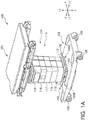
- the adjustable support apparatus 100 includes a telescoping column 110, a base 103, and a table top assembly 104.
- the base 103 may include a plurality of casters 105 such that the adjustable support apparatus 100 may be moved along a surface such as a floor.
- the telescoping column 110 is positioned on and supported by the base 103.
- the table top assembly 104 may be configured to support a patient thereon and is positioned on and supported by the telescoping column 110.
- the table top assembly 104 is selectively removable from the telescoping column 110.
- the telescoping column 110 may be adapted to have a table top assembly 104 affixed thereto and removed therefrom.
- the base 103 may be adapted to have a telescoping column 110 affixed thereto and removed therefrom. Accordingly, it should be understood that the telescoping column 110 may be an assembly separate and distinct from the base 103 and the table top assembly 104.
- the telescoping column 110 includes an adjustment system (not shown) for raising and lowering the table top assembly 104 relative to the base 103 and/or tilting the table top assembly 104 relative to the base 103.
- FIG. 1A illustrates the telescoping column 110 in an extended configuration.
- FIG. 1B the telescoping column 110 is shown in a retracted configuration.
- the adjustment system may facilitate rotating the table top assembly 104 about an axis generally parallel with the +/-Z axis depicted in FIG. 1A , rotating the table top assembly 104 about an axis generally parallel with the +/- Y axis depicted in FIG.
- the adjustment system may be a mechanical adjustment system, an electro-mechanical adjustment system, a hydraulic adjustment system, or combinations thereof.
- the adjustment system may include a spindle mechanism that is driven by an electric motor for raising and lowering the telescoping column 110.
- the adjustment system may be positioned within the telescoping column 110.
- the telescoping column 110 includes a base support 112 coupled to the base 103 and a plurality of nestable cassettes 114 (i.e., cassettes 115, 116, 117, 118, and 119 in FIG. 1A ) extending between the base support 112 and the table top assembly 104.
- the base support 112 and the plurality of nestable cassettes 114 form a cladding (i.e., the exterior surface) of the telescoping column 110.
- the cladding encloses and conceals the adjustment system of the adjustable support apparatus 100.
- the cladding may be made from, for example, stainless steel or other suitable material capable of being washed and sterilized.
- the plurality of nestable cassettes 114 are supported on the base support 112 and are actuatable, such as with the adjustment system, to extend and retract in a vertical direction relative to the base support 112.
- a base cassette 115 is directly engaged with the base support 112 and is configured to slide over a perimeter of the base support 112 in a +Z direction when the column is transitioning to an extended position, as illustrated in FIG. 1A , and in a -Z direction when the telescoping column 110 is transitioning to a retracted position, as illustrated in FIG. 1B .
- a first intermediate cassette 116 may be directly engaged with the base cassette 115 and is configured to slide over a perimeter of the base cassette 115 in a +Z direction when the column is transitioning to an extended position, as illustrated in FIG. 1A , and in a -Z direction when the telescoping column 110 is transitioning to a retracted position, as illustrated in FIG. 1B .
- Subsequent intermediate cassettes 117, 118 may be similarly engaged with each preceding cassette until a master cassette 119 is reached. In this way, each consecutive cassette of the plurality of nestable cassettes 114 may have a greater perimeter compared to the immediately preceding cassette.
- a master cassette 119 may be the last cassette of the plurality of nestable cassettes 114, and may have the largest perimeter of the plurality of cassettes 114.
- the master cassette 119 may similarly be engaged with and move relative to an immediately preceding intermediate cassette 118 as described above with respect to the base cassette 115 and the first intermediate cassette 116.
- the master cassette 119 is coupled to the underside of the table top assembly 104 and is directly engaged with an immediately preceding intermediate cassette 118 and is configured to slide over an outer surface of the immediately preceding intermediate cassette 118 in a +Z direction when the column is transitioning to an extended position, as illustrated in FIG. 1A , and in a -Z direction when the telescoping column 110 is transitioning to a retracted position, as illustrated in FIG.
- Each cassette of the plurality of nestable cassettes 114 may be coupled with the immediately preceding cassette through a variety of conventional coupling techniques including, but not limited to, interference structures, hooks, pins, and the like.
- the intermediate cassette 116 may contain a flange (not shown) that extends from the top edge of the intermediate cassette 116 inward, towards the center of the telescoping column 110.
- the intermediate cassette 117 may have a corresponding flange (not shown) that extends from the bottom edge of the intermediate cassette 117 outward, away from the center of the telescoping column 110.
- the intermediate cassette 116 and the intermediate cassette 117 may also be coupled to the adjustment system such that the intermediate cassette 116 and the intermediate cassette 117 are raised or lowered with the table top assembly 104. As the table top assembly 104 is raised, for example, the flange of the intermediate cassette 116 engages with the corresponding flange of the intermediate cassette 117, drawing the intermediate cassette 116 over the base cassette 115. Each adjacent pair of adjacent cassettes in the plurality of nestable cassettes 114 may be similarly coupled to facilitate the "telescoping" effect of the telescoping column 110.
- This telescoping effect is also enabled by the relative dimensions of each of the cassettes of the plurality of nestable cassettes 114.
- a perimeter of each consecutive nestable cassette of the plurality of nestable cassettes 114 may increase from the base support 112 in the +Z direction.
- the master cassette 119 may define a largest perimeter of the plurality of nestable cassettes 114.
- FIG. 4 a schematic side view of the telescoping column 110 is illustrated. It is noted that the dimensions of the various cassettes have been exaggerated to better illustrate the consecutively increasing perimeter of each cassette.
- a projected perimeter 219 of the master cassette 119 circumscribes a perimeter of the at least one intermediate cassette (e.g., cassette 116, 117, and/or 118) and a projected perimeter (e.g., projected perimeter 216, 217, and/or 218) of the at one least intermediate cassette circumscribes a perimeter of the base cassette 115 such that the base cassette 115 is nestable within the at least one intermediate cassette and the at least one intermediate cassette is nestable within the master cassette 119.
- the at least one intermediate cassette e.g., cassette 116, 117, and/or 118
- a projected perimeter e.g., projected perimeter 216, 217, and/or 21
- FIG. 5 schematically illustrates a top view of the telescoping column 110 to further illustrate the consecutively increasing perimeters of each cassette of the plurality of nestable cassettes 114 from the base cassette 115 to the master cassette 119 and the relative orientations of the perimeter of each cassette with respect to one another.
- the telescoping column 110 is illustrated as having five cassettes, the plurality of nestable cassettes 114 may contain more or fewer cassettes.
- the telescoping column 110 includes at least the base cassette 115, the master cassette 119, and at least one intermediate cassette (e.g., 116, 117, and/or 118) positioned between the base cassette 115 and the master cassette 119.
- the perimeters of the cassettes of the plurality of nestable cassettes 114 are illustrated generally as quadrilaterals, it is contemplated that the perimeters of the cassettes may be any shape wherein each consecutive cassette is nestable within the immediately preceding cassette.
- the cassettes include perimeters that are round, triangular, octagonal, irregular, etc.
- the telescoping column 110 As the telescoping column 110 is actuated to increase and decrease in height, objects positioned within the vicinity of the telescoping column 110 may catch on or otherwise interfere with the movement of the plurality of nestable cassettes 114. For example, if an object were placed on the base 103 of the adjustable support apparatus 100 and in direct contact with the outer surface of the base cassette 115, the object may interfere with the telescoping action of the telescoping column 110. That is, the object may, for example, prevent the base cassette 115 from being nested within the intermediate cassette 116 when the telescoping column 110 is moved from the extended configuration to the retracted configuration. Such interference would prevent operation of the telescoping column 110 and could lead to damage to the telescoping column 110 and/or the adjustment system.
- a cladding protection unit 150 is placed around the telescoping column 110 to prevent placement of objects within the vicinity of the plurality of nestable cassettes 114 without disturbing the ability of the telescoping column 110 to fully extend and retract.
- the cladding protection unit 150 is positioned on the base 103 and is removably coupled around a perimeter of the telescoping column 110.
- the cladding protection unit 150 is removably coupled around the perimeter of the telescoping column 110 as defined by the base support 112 of the telescoping column 110.
- the cladding protection unit 150 may be sized to fit around the base support 112 beneath the base cassette 115 when the base cassette 115 is in its lowest retracted position (see FIG. 1B ).
- the cladding protection unit 150 may fit around the base support 112 of the telescoping column 110 without interfering with the vertical raising and lowering of the plurality of nestable cassettes 114.
- the cladding protection unit 150 may have a height in the +Z direction between about 50 mm and 100 mm (e.g., about 62 mm). However, larger and smaller heights are also contemplated.
- the cladding protection unit 150 may be sized to fit around the base support 112 and at least the base cassette 115 when the base cassette 115 is in its lowest retracted position such that the base cassette 115 is nestable within a column receiving space 158 (shown in FIGS.
- a projected perimeter (not shown) of the column receiving space 158 may circumscribe the perimeter of the base cassette 115 such that at least the base cassette 115 is nestable within the column receiving space 158.
- the cladding protection unit 150 may be made from, for example, stainless steel sheet metal or other material capable of being washed and sterilized.
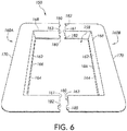
- FIG. 6 illustrates a top perspective view of the cladding protection unit 150 in isolation from the telescoping column 110 and in a disassembled state (i.e., the first portion 160A is uncoupled from the second portion 160B).
- the cladding protection unit 150 generally includes a frame 152 and a standoff flange 170.
- the frame 152 defines and at least partially encloses a column receiving space 158 in which the telescoping column 110 may be positioned.
- the standoff flange 170 generally extends from the frame 152 away from the column receiving space 158.
- the frame 152 and standoff flange 170 may be formed as a unitary construct (not shown), such as when the frame 152 is formed as a closed loop around the column receiving space 158 and the standoff flange 170 is welded or integrally formed with the frame 152.
- the standoff flange 170 and frame 152 may be a multi-part construct, as depicted in FIG. 6 .
- the frame 152 of the cladding protection unit 150 may include at least a first portion 160A and a second portion 160B that are separable from one another.
- the first portion 160A and the second portion 160B of the frame 152 are combined, the first portion 160A and the second portion 160B enclose the column receiving space 158 such that the frame 152 extends around a perimeter of the telescoping column 110, as depicted in FIGS. 1A-5 , when the telescoping column 110 is positioned in the column receiving space 158.
- the cladding protection unit 150 may be easily placed around and removed from around the telescoping column 110.
- the cladding protection unit 150 when the cladding protection unit 150 is assembled around the telescoping column 110, by disconnecting the first portion 160A from the second portion 160B, each of the first portion 160A and the second portion 160B may be removed from around the telescoping column 110 to facilitate, for example, cleaning and sanitizing the cladding protection unit 150 and/or the telescoping column 110.
- each of the first and second portions 160A, 160B may make up approximately one half of the cladding protection unit 150. However, it is contemplated that in other embodiments the first and second portions 160A, 160B may not make up equal portions of the cladding protection unit 150.
- the first portion 160A may be substantially identical to the second portion 160B. By making the first portion 160A and the second portion 160B substantially identical to one another, manufacture of the cladding protection unit 150 may be simplified.
- both the first portion 160A and the second portion 160B may include the same elements, but when combined, one of the first portion 160A and the second portion 160B is rotated so as to be the reverse orientation of the other portion.
- only one of the first portion 160A and the second portion 160B need be repeatedly manufactured to produce a cladding protection unit 150. This may simplify manufacturing and reduce associated costs.
- substantially identical elements of the first and second portions 160A, 160B are described using the same reference numerals.
- Each of the first and second portions 160A, 160B includes a first end 161 and a second end 163 spaced apart from the first end 161.
- FIG. 7 illustrates, in isolation, a top view of the cladding protection unit 150 in an assembled state.
- the first end 161 of the first portion 160A may be configured to be coupled to the second end 163 of the second portion 160B.
- the second end 163 of the first portion 160A may be configured to be coupled to the first end 161 of the second portion 160B.
- the first and second portions 160A, 160B may be coupled to one another through a variety of fastening techniques that allow for the cladding protection unit 150 to be readily assembled and disassembled.
- the first portion 160A may be configured to be magnetically coupled to the second portion 160B.
- the cladding protection unit 150 and the column receiving space 158 are illustrated as quadrilaterals, it is contemplated that the cladding protection unit 150 may be any shape generally corresponding to the shape of the base support 112 of the telescoping column 110. In some embodiments, the shape of the cladding protection unit 150 may not correspond directly with the contours of the telescoping column 110.
- FIG. 7 illustrates a top view of the assembled cladding protection 150 unit
- FIG. 8 illustrates a front view of the assembled cladding protection unit 150
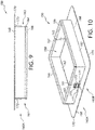
- FIG. 9 illustrates a side view of the assembled cladding protection unit 150
- FIG. 10 illustrates an upside-down perspective view of the assembled cladding protection unit 150.
- Each of the first portion 160A and the second portion 160B of the frame 152 of the cladding protection unit 150 includes a sidewall 162.
- the sidewall 162 may extend substantially parallel in the +Z direction to the base support 112 of the telescoping column 110.
- the sidewall 162 may be positioned proximate to the outer surface of the base support 112 when the cladding protection unit 150 is assembled around the telescoping column 110. In some embodiments, the sidewall 162 may positioned in contact with the base support 112 of the telescoping column 110 when the cladding protection unit 150 is assembled around the telescoping column 110.
- a resilient material 164 may be applied to the base portion 166 of the sidewall 162.
- the resilient material 164 may extend up a portion of the sidewall 162 on either side of the sidewall 162.
- the resilient material 164 may provide a smooth edge for sliding the first and second portions 160A, 160B of the cladding protection unit 150 along the base 103 of the adjustable support apparatus 100, as illustrated in FIGS. 1A-3 .
- the resilient material 164 may further provide a protective barrier between the cladding protection unit 150 and the base 103 of the adjustable support apparatus 100 to minimize scratching that may otherwise be caused to the base 103 of the adjustable support apparatus 100 when the cladding protection unit 150 is slid into place around the base support 112 of the telescoping column 110. In some embodiments, there may be no resilient material 164 added to the base portion 166 of the sidewall 162.
- the cladding protection unit 150 further comprises a standoff flange 170, as described herein.
- the standoff flange 170 extends from the sidewall 162 away from the column receiving space 158.
- the standoff flange 170 may be positioned at a top 168 of the sidewall 162 located opposite of the base portion 166, as depicted in the figures.
- the standoff flange 170 may extend outward from the sidewall 162 at a position between the top 168 and the base portion 166.
- the standoff flange 170 defines an outer perimeter 154 of the cladding protection unit 150.
- the standoff flange 170 may be coupled to the sidewall 162 of the first and second portions 160A, 160B through any conventional joining technique (e.g., fasteners, adhesives, welding, and the like) or may be integrally formed with the sidewall 162.
- the material of the standoff flange 170 may have a substantially constant thickness.
- the standoff flange 170 of the cladding protection unit 150 may have thickness from about 1 mm to about 5 mm (e.g., about 2 mm).
- the material of the sidewall 162 has the same thickness as the standoff flange 170. It is noted that though the standoff flange 170 is illustrated as extending from the sidewall 162 at a substantially perpendicular orientation relative to the sidewall 162, it is also contemplated the that the standoff flange 170 may extend from the sidewall 162 at an oblique angle relative to the sidewall 162.
- a projected perimeter 254 of the standoff flange 170 which corresponds to the outer perimeter 154 of the standoff flange 170 illustrated in FIGS. 5 and 7 , circumscribes a perimeter of the master cassette 119 (see projected perimeter 219). See also, FIG. 5 , which illustrates that the outer perimeter 154 of the cladding protection unit is larger than a perimeter of the master cassette 119.
- the standoff flange 170 in the illustrated embodiments extends on all sides of the telescoping column 110.
- the standoff flange 170 may not extend on all sides of the telescoping column 110 but may instead be intermittent along the perimeter 154 of the cladding protection unit 150. Accordingly, the standoff flange 170 may act as a deterrent to placing objects too close to the plurality of nestable cassettes 114 of the telescoping column 110. Specifically, the standoff flange 170 prevents objects from being placed close enough to the telescoping column 110 to interfere with the plurality of nestable cassettes 114 as the table top assembly 104 is raised and lowered.
- the standoff flange 170 may extend far enough from the sidewall 162 to be a deterrent to placing objects too close to the telescoping column 110 while still allowing some of the space between the base 103 and the table top assembly 104 to be used.
- the adjustable support apparatus 100 is an operating table
- medical equipment or the feet of a surgeon or other staff may be able to rest upon the base 103 without interfering with the cladding protection unit 150 or the telescoping column 110.
- first and second portions 160A, 160B of the cladding protection unit 150 may be magnetically coupled to one another.
- one or more magnets 171 may be coupled to at least one of the first and second portions 160A, 160B of the frame 152 to magnetically couple the first portion 160A to the second portion 160B.
- the one or more magnets 171 may be positioned along an outer surface of the sidewall 162 proximate to the standoff flange 170 at at least one of the first end 161 and the second end 163 of the at least one of the first and second portions 160A, 160B.
- both the first portion 160A and the second portion 160B may each include a magnet 171 with an opposite pole exposed from the other portion.
- the first portion 160A could include a first magnet 172 with a positive pole exposed and the second portion 160B could include a second magnet 173 with a negative pole exposed.
- the one or more magnets 171 may be located at both the first and second ends 161,163 of the first and second portions 160A, 160B.
- the one or more magnets 171 for each of the first and second portions 160A, 160B may include a first magnet 172 located at one of the first end 161 and the second end 163 of each of the first and second portions 160A, 160B and a second magnet 173 located at the end 161 or 163 opposite the first magnet 172 of each of the first and second portions 160A, 160B.
- the first magnet 172 coupled to the first portion 160A is configured to be magnetically coupled to the second magnet 173 coupled to the second portion 160B
- the first magnet 172 coupled to the second portion 160B is configured to be magnetically coupled to the second magnet 173 coupled to the first portion 160A.
- the one or more magnets 171 may be coupled to the frame 152 of the cladding protection unit 150 in a variety of ways.
- the one or more magnets 171 may be fastened to the sidewall 162 by threaded fasteners. Other conventional joining techniques include but are not limited to, soldering, brazing, adhesive bonding, and the like.
- the one or more magnets 171 may be coupled to a surface of the standoff flange 170.
- the one or more magnets 171 may be coupled to the sidewall 162 and in contact with the standoff flange 170. It is further noted that by providing a magnetic coupling between the first portion 160A and the second portion 160B the cladding protection unit 150 may be easily cleaned and sterilized for sterile environments, such as, for example, an operating room.
- the standoff flange 170 may aid in decoupling the first portion 160A from the second portion 160B of the cladding protection unit 150. For example, pressing on the standoff flange 170 may provide leverage to overcome the magnetic attraction between the first portion 160A and the second portion 160B caused by the one or more magnets 171.
- first portion 160A and the second portion 160B of the cladding protection unit 150 may be coupled with mechanical fasteners, mechanical latches, or the like.
- the first and second portions 160A, 160B may be configured to interlock with one another.
- the first and second portions 160A, 160B may include one or more guiding members 180 and/or one or more receiving slots 182 configured to receive the one or more guiding members 180 of the opposite portion.
- the one or more guiding members 180 may be a protrusion extending from at least one of the first and second ends 161, 163 of at least one of the first and second portions 160A, 160B.
- the one or more receiving slots 182 may be a cutout positioned within at least one of the first and second ends 161, 163 of at least one of the first and second portions 160A, 160B.
- the first portion 160A of the frame 152 may include one or more guiding members 180 and the second portion 160B may include one or more receiving slots 182 for receiving the one or more guiding members 180 of the first portion 160A.
- each of the first portion 160A and the second portion 160B include one or more guiding members 180 and each of the first portion 160A and the second portion 160B include one or more receiving slots 182.
- the one or more receiving slots 182 of the first portion 160A are configured to correspond with and receive the one or more guiding members 180 of the second portion 160B and the one or more receiving slots 182 of the second portion 160B are configured to correspond with and receive the one or more guiding members 180 of the first portion 160A.
- the one or more guiding members 180 may include any geometry (e.g., semi-circular, rectangular, and the like) and size while the one or more receiving slots 182 may include an inverse geometry and size to match the geometry and size of the one or more guiding members 180.
- the one or more guiding members 180 and the one or more receiving slots 182 may provide a more secure coupling between the first portion 160A and the second portion 160B.
- the one or more guiding members 180 and the one or more receiving slots 182 may provide indications to a user of the appropriate orientation of the first portion 160A and the second portion 160B to couple the first portion 160A to the second portion 160B.
- the one or more guiding members 180 and the one or more receiving slots 182 may be laser cut, which may provide a more precise and seamless fit between the one or more guiding members 180 and the one or more receiving slots 182.
- the first ends 161 of the first and second portions 160A, 160B include two guiding members 180 wherein one guiding member 180 extends from the standoff flange 170 and the second guiding member 180 extends from the sidewall 162.
- the second ends 163 of the first and second portions 160A, 160B include two receiving slots 182, wherein one receiving slot 182 is positioned within the standoff flange 170 and the other receiving slot 182 is positioned within the sidewall 162, beneath the magnet 171.
- the one or more guiding members 180 and one or more guiding ports 182 may be positioned on only one of the standoff flange 170 or the sidewall 162.
- the cladding protection units described herein can be placed around the base of a telescoping column to discourage the placement of objects within a vicinity of the telescoping column.
- the cladding protection unit may discourage the placement of objects near the telescoping column that could interfere with the extension or retraction of the various cassettes of the telescoping column and damage the cassettes.
- the cladding protection unit may be easily assembled and disassembled for cleaning and sterilization for use in operating rooms or other sterile environments.
Landscapes
- Health & Medical Sciences (AREA)
- Engineering & Computer Science (AREA)
- Biomedical Technology (AREA)
- Life Sciences & Earth Sciences (AREA)
- Animal Behavior & Ethology (AREA)
- General Health & Medical Sciences (AREA)
- Public Health (AREA)
- Veterinary Medicine (AREA)
- General Engineering & Computer Science (AREA)
- Mechanical Engineering (AREA)
- Accommodation For Nursing Or Treatment Tables (AREA)
- Battery Mounting, Suspending (AREA)
Claims (15)
- Teleskopsäulenbaugruppe (110), die Folgendes umfasst: eine Teleskopsäule, die mehrere verschachtelbare Kassetten (114) umfasst, wobei die mehreren verschachtelbaren Kassetten Folgendes umfassen: eine Basiskassette (115); wenigstens eine Zwischenkassette (116, 117, 118), die mit der Basiskassette (115) gekoppelt ist; und eine Masterkassette (119), die mit der wenigstens einen Zwischenkassette gekoppelt ist, wobei ein projizierter Umfang der Masterkassette (119) einen Umfang der wenigstens einen Zwischenkassette (116, 117, 118) umschreibt und ein projizierter Umfang der wenigstens einen Zwischenkassette (116, 117, 118) einen Umfang der Basiskassette (115) umschreibt, so dass die Basiskassette (115) in der wenigstens einen Zwischenkassette (116, 117, 118) verschachtelt werden kann und die wenigstens eine Zwischenkassette in der Masterkassette (119) verschachtelt werden kann; dadurch gekennzeichnet, dass sie ferner eine Verkleidungsschutzeinheit (150) umfasst, die so positioniert ist, dass sie einen Umfang der Teleskopsäule umgibt, wobei die Verkleidungsschutzeinheit (150) Folgendes umfasst: eine Seitenwand (162), die einen Säulenaufnahmeraum bildet; und einen Abstandsflansch (170), der sich von der Seitenwand (162) weg von dem Säulenaufnahmeraum erstreckt, wobei ein projizierter Umfang (254) des Abstandsflansches (170) den Umfang (219) der Masterkassette (119) umschreibt.
- Teleskopsäulenbaugruppe nach Anspruch 1, wobei die Verkleidungsschutzeinheit in einen ersten Abschnitt und einen zweiten Abschnitt unterteilt werden kann.
- Teleskopsäulenbaugruppe nach Anspruch 2, wobei der erste Abschnitt der Verkleidungsschutzeinheit magnetisch mit dem zweiten Abschnitt der Verkleidungsschutzeinheit gekoppelt ist.
- Teleskopsäulenbaugruppe nach Anspruch 2 oder Anspruch 3, wobei:der erste und zweite Abschnitt der Verkleidungsschutzeinheit jeweils ein erstes Ende und ein vom ersten Ende beabstandetes zweites Ende umfassen; unddie Verkleidungsschutzeinheit ferner Folgendes umfasst:einen ersten Magnet, der sich am ersten Ende und am zweiten Ende des ersten Abschnitts und des zweiten Abschnitts befindet; undeinen zweiten Magnet, der sich an einem Ende gegenüber dem ersten Magnet befindet, undwobei der mit dem ersten Abschnitt gekoppelte erste Magnet magnetisch mit dem mit dem zweiten Abschnitt gekoppelten zweiten Magnet gekoppelt ist und der mit dem zweiten Abschnitt gekoppelte erste Magnet magnetisch mit dem mit dem ersten Abschnitt gekoppelten zweiten Magnet gekoppelt ist.
- Teleskopsäulenbaugruppe nach einem der Ansprüche 2 bis 4, wobei:der erste Abschnitt ein oder mehrere Führungselemente umfasst und der zweite Abschnitt einen oder mehrere Aufnahmeschlitze umfasst; unddie ein oder mehreren Führungselemente des ersten Abschnitts den ein oder mehreren Aufnahmeschlitzen des zweiten Abschnitts entsprechen.
- Teleskopsäulenbaugruppe nach einem der Ansprüche 2 bis 4, wobei:der erste Abschnitt und der zweite Abschnitt jeweils ein oder mehrere Führungselemente und einen oder mehrere Aufnahmeschlitze aufweisen;die ein oder mehreren Führungselemente des ersten Abschnitts den ein oder mehreren Aufnahmeschlitzen des zweiten Abschnitts entsprechen; unddie ein oder mehreren Führungselemente des zweiten Abschnitts den ein oder mehreren Aufnahmeschlitzen des zweiten Abschnitts entsprechen.
- Teleskopsäule nach einem vorherigen Anspruch, wobei die Teleskopsäule an einer Basis positioniert ist und die Teleskopsäule eine Tischplattenbaugruppe trägt.
- Teleskopsäule nach Anspruch 7, wobei die Basiskassette auf der Basis getragen wird und die Masterkassette mit der Tischplattenbaugruppe gekoppelt ist.
- Verkleidungsschutzeinheit (150) für eine Säule einer justierbaren Tragvorrichtung, wobei die Verkleidungsschutzeinheit (150) Folgendes umfasst: einen Rahmen, der einen ersten Abschnitt (160A) und einen zweiten Abschnitt (160B) umfasst, die zum magnetischen Koppeln miteinander konfiguiert sind, wobei der erste Abschnitt (160A) und der zweite Abschnitt (160B) jeweils Folgendes umfassen: eine Seitenwand (162), wobei die Seitenwand (162) des ersten Abschnitts des Rahmens und die Seitenwand (162) des zweiten Abschnitts des Rahmens einen Säulenaufnahmeraum (158) bilden, wenn der erste Abschnitt magnetisch mit dem zweiten Abschnitt gekoppelt ist; und einen Abstandsflansch (170), der sich von der Seitenwand (162) nach außen erstreckt; und einen oder mehrere Magnete (171), die mit dem ersten Abschnitt (160A) und/oder dem zweiten Abschnitt des Rahmens gekoppelt sind, um den ersten Abschnitt magnetisch mit dem zweiten Abschnitt (160B) zu koppeln, wobei, wenn die Verkleidungsschutzeinheit (150) um einen Umfang der Säule der justierbaren Tragvorrichtung positioniert ist, die Säule im Säulenaufnahmeraum (158) des Rahmens positioniert ist und der Abstandsflansch (170) des Rahmens sich von einem Umfang der Säule (219) nach außen erstreckt.
- Verkleidungsschutzeinheit nach Anspruch 9, wobei der Abstandsflansch des ersten Abschnitts und der Abstandsflansch des zweiten Abschnitts einen Außenumfang der Verkleidungsschutzeinheit definieren, wenn der erste Abschnitt des Rahmens mit dem zweiten Abschnitt des Rahmens gekoppelt ist.
- Verkleidungsschutzeinheit nach Anspruch 9 oder Anspruch 10, wobei die ein oder mehreren Magnete entlang einer Außenfläche der Seitenwand in der Nähe des Abstandsflansches am ersten Ende und/oder am zweiten Ende des ersten Abschnitts und/oder des zweiten Abschnitts positioniert sind.
- Verkleidungsschutzeinheit nach einem der Ansprüche 9 bis 11, wobei:die ein oder mehreren Magnete einen ersten Magnet beinhalten, der sich am ersten Ende oder am zweiten Ende des ersten bzw. zweiten Abschnitts befindet, und einen zweiten Magnet, der sich an einem Ende gegenüber dem ersten Magnet jeweils des ersten und zweiten Abschnitts befindet; undwobei der mit dem ersten Abschnitt gekoppelte erste Magnet so konfiguriert ist, dass er magnetisch mit dem mit dem zweiten Abschnitt gekoppelten zweiten Magnet gekoppelt ist, und der mit dem zweiten Abschnitt gekoppelte erste Magnet so konfiguriert ist, dass er magnetisch mit dem mit dem ersten Abschnitt gekoppelten zweiten Magnet gekoppelt ist.
- Verkleidungsschutzeinheit nach einem der Ansprüche 9 bis 12, wobei die Seitenwand einen Basisabschnitt und eine Oberseite aufweist, wobei sich der Abstandsflansch von der Seitenwand am oberen Ende der Seitenwand nach außen erstreckt.
- Verkleidungsschutzeinheit nach einem der Ansprüche 9 bis 13, wobei der erste Abschnitt so konfiguriert ist, dass er mit dem zweiten Abschnitt verriegelt wird.
- Verkleidungsschutzeinheit nach Anspruch 14, wobei der erste Abschnitt und der zweite Abschnitt jeweils ein oder mehrere Führungselemente umfassen und der erste Abschnitt und der zweite Abschnitt jeweils einen oder mehrere Aufnahmeschlitze aufweisen, wobei die ein oder mehreren Aufnahmeschlitze des ersten Abschnitts zum Aufnehmen der ein oder mehreren Führungselemente des zweiten Abschnitts konfiguriert sind und die ein oder mehreren Aufnahmeschlitze des zweiten Abschnitts zum Aufnehmen der ein oder mehreren Führungselemente des ersten Abschnitts konfiguriert sind.
Applications Claiming Priority (1)
| Application Number | Priority Date | Filing Date | Title |
|---|---|---|---|
| US201762491696P | 2017-04-28 | 2017-04-28 |
Publications (2)
| Publication Number | Publication Date |
|---|---|
| EP3395314A1 EP3395314A1 (de) | 2018-10-31 |
| EP3395314B1 true EP3395314B1 (de) | 2020-02-12 |
Family
ID=62063463
Family Applications (1)
| Application Number | Title | Priority Date | Filing Date |
|---|---|---|---|
| EP18169373.0A Active EP3395314B1 (de) | 2017-04-28 | 2018-04-25 | Verkleidungsschutzeinheiten für teleskopsäulen und verstellbare stützvorrichtungen |
Country Status (4)
| Country | Link |
|---|---|
| US (1) | US10952913B2 (de) |
| EP (1) | EP3395314B1 (de) |
| AU (1) | AU2018202713B2 (de) |
| CA (1) | CA3002465C (de) |
Families Citing this family (5)
| Publication number | Priority date | Publication date | Assignee | Title |
|---|---|---|---|---|
| TWI684439B (zh) * | 2019-04-24 | 2020-02-11 | 明基三豐醫療器材股份有限公司 | 工作檯柱 |
| US11957627B2 (en) | 2020-10-09 | 2024-04-16 | Robert Dan Allen | Surgical table cladding protective device |
| CN114380236A (zh) * | 2022-01-28 | 2022-04-22 | 中北大学 | 一种多方位物料搬运用agv小车 |
| WO2024250063A1 (en) * | 2023-06-05 | 2024-12-12 | Genesis Safety Pty Ltd | Height adjustable change table |
| EP4717122A1 (de) * | 2024-09-30 | 2026-04-01 | Linhai Baocheng Crafts Co., Ltd | Pneumatischer hubtisch |
Family Cites Families (13)
| Publication number | Priority date | Publication date | Assignee | Title |
|---|---|---|---|---|
| DE8907197U1 (de) | 1989-06-13 | 1990-01-11 | Völker Möbelproduktionsgesellschaft mbH, 5810 Witten | Pflege- und/oder Krankenbett mit in den Eckholmen des Bettgestelles geführten und gelagerten Fußstützen die teleskopartig verstellbar sind |
| DE4423402C2 (de) | 1994-07-04 | 1999-12-30 | Maquet Ag | Stützsäule zur Halterung einer Patientenlagerfläche |
| US20030190189A1 (en) | 2001-04-13 | 2003-10-09 | Sentry Protection Products, Inc. | Apparatus for protecting structural supports |
| DE102005053753A1 (de) | 2005-11-10 | 2007-05-16 | Maquet Gmbh & Co Kg | Hydraulische Säulenklemmung |
| WO2007065073A2 (en) | 2005-11-23 | 2007-06-07 | New Pig Corporation | Protective utility pole base covers |
| DE102007055463A1 (de) | 2007-11-13 | 2009-05-28 | Trumpf Medizin Systeme Gmbh | Operationstischsäule |
| DE202008008574U1 (de) * | 2008-06-25 | 2008-08-28 | Maquet Gmbh & Co. Kg | Verkleidung einer höhenverstellbaren Stützsäule |
| DE102014104681B4 (de) | 2014-04-02 | 2018-02-08 | MAQUET GmbH | Operationstischsäule und Operationstisch mit einer derartigen Operationstischsäule |
| US9782315B2 (en) | 2014-05-21 | 2017-10-10 | Wylie McCoy Langford | Shroud guard for surgical tables |
| DE102014109376B4 (de) | 2014-07-04 | 2017-11-09 | MAQUET GmbH | Operationstischfuß für einen Operationstisch |
| US9233042B1 (en) | 2014-09-14 | 2016-01-12 | Michael Freude | Surgical table guard |
| DE102015100542B4 (de) | 2015-01-15 | 2018-08-30 | MAQUET GmbH | Operationstischsäule |
| US10610435B2 (en) * | 2017-09-15 | 2020-04-07 | Robert Dan Allen | Surgical table cladding protective device |
-
2018
- 2018-04-16 US US15/953,552 patent/US10952913B2/en active Active
- 2018-04-18 AU AU2018202713A patent/AU2018202713B2/en active Active
- 2018-04-24 CA CA3002465A patent/CA3002465C/en active Active
- 2018-04-25 EP EP18169373.0A patent/EP3395314B1/de active Active
Non-Patent Citations (1)
| Title |
|---|
| None * |
Also Published As
| Publication number | Publication date |
|---|---|
| CA3002465C (en) | 2022-03-15 |
| CA3002465A1 (en) | 2018-10-28 |
| AU2018202713A1 (en) | 2018-11-15 |
| US10952913B2 (en) | 2021-03-23 |
| US20180311101A1 (en) | 2018-11-01 |
| EP3395314A1 (de) | 2018-10-31 |
| AU2018202713B2 (en) | 2020-12-03 |
Similar Documents
| Publication | Publication Date | Title |
|---|---|---|
| EP3395314B1 (de) | Verkleidungsschutzeinheiten für teleskopsäulen und verstellbare stützvorrichtungen | |
| EP1245213A2 (de) | Verfahren und Vorrichtung zur Abdeckung eines verstellbaren Patiententisches | |
| US9233042B1 (en) | Surgical table guard | |
| US20210169601A1 (en) | Cantilever organizational rack system for supporting surgical instrumentation | |
| ES2220441T3 (es) | Dispositivo de aspiracion de emanaciones instalado en una zona proxima a zonas de cocinado al descubierto. | |
| US9078597B2 (en) | Mobile x-ray unit with integrated x-ray shield | |
| EP3362021B1 (de) | Patientenwagen und patiententransfervorrichtung | |
| US20090165771A1 (en) | Foldable and removable side table for bbq grill | |
| JP5000710B2 (ja) | 手術台の案内装置 | |
| EP2174322A1 (de) | Untere abschirmung für ein strahlungsschutzsystem | |
| US20110126353A1 (en) | Bedside assistance apparatus | |
| JP2004522495A (ja) | 手術台 | |
| EP1863423A1 (de) | Höhenverstellbare bettgestelle | |
| US20080031422A1 (en) | X-Ray Device with a Scattered Ray Protection Device | |
| JP5975609B2 (ja) | カート装置 | |
| ZA200201108B (en) | Dropping side shelf assembly | |
| US12178328B2 (en) | Mobile unit comprising a collapsible dome-shaped hood | |
| US20220249036A1 (en) | Radiation shielding devices, systems, and methods | |
| JP2016214898A (ja) | カート装置 | |
| CN222110574U (zh) | 一种拉篮组件及消毒柜 | |
| CN217014515U (zh) | 一种输液盘支架和安装输液盘支架的病床 | |
| JP3207582U (ja) | ストレッチャー | |
| JP7854844B2 (ja) | 移動式什器 | |
| CN213310366U (zh) | 一种急诊室治疗工具托盘装置 | |
| CN216061716U (zh) | 一种磁共振引导的hifu治疗床 |
Legal Events
| Date | Code | Title | Description |
|---|---|---|---|
| PUAI | Public reference made under article 153(3) epc to a published international application that has entered the european phase |
Free format text: ORIGINAL CODE: 0009012 |
|
| STAA | Information on the status of an ep patent application or granted ep patent |
Free format text: STATUS: THE APPLICATION HAS BEEN PUBLISHED |
|
| AK | Designated contracting states |
Kind code of ref document: A1 Designated state(s): AL AT BE BG CH CY CZ DE DK EE ES FI FR GB GR HR HU IE IS IT LI LT LU LV MC MK MT NL NO PL PT RO RS SE SI SK SM TR |
|
| AX | Request for extension of the european patent |
Extension state: BA ME |
|
| STAA | Information on the status of an ep patent application or granted ep patent |
Free format text: STATUS: REQUEST FOR EXAMINATION WAS MADE |
|
| 17P | Request for examination filed |
Effective date: 20190411 |
|
| RBV | Designated contracting states (corrected) |
Designated state(s): AL AT BE BG CH CY CZ DE DK EE ES FI FR GB GR HR HU IE IS IT LI LT LU LV MC MK MT NL NO PL PT RO RS SE SI SK SM TR |
|
| GRAP | Despatch of communication of intention to grant a patent |
Free format text: ORIGINAL CODE: EPIDOSNIGR1 |
|
| STAA | Information on the status of an ep patent application or granted ep patent |
Free format text: STATUS: GRANT OF PATENT IS INTENDED |
|
| GRAJ | Information related to disapproval of communication of intention to grant by the applicant or resumption of examination proceedings by the epo deleted |
Free format text: ORIGINAL CODE: EPIDOSDIGR1 |
|
| GRAP | Despatch of communication of intention to grant a patent |
Free format text: ORIGINAL CODE: EPIDOSNIGR1 |
|
| INTG | Intention to grant announced |
Effective date: 20190801 |
|
| GRAJ | Information related to disapproval of communication of intention to grant by the applicant or resumption of examination proceedings by the epo deleted |
Free format text: ORIGINAL CODE: EPIDOSDIGR1 |
|
| GRAP | Despatch of communication of intention to grant a patent |
Free format text: ORIGINAL CODE: EPIDOSNIGR1 |
|
| INTG | Intention to grant announced |
Effective date: 20190828 |
|
| INTG | Intention to grant announced |
Effective date: 20190911 |
|
| GRAS | Grant fee paid |
Free format text: ORIGINAL CODE: EPIDOSNIGR3 |
|
| GRAA | (expected) grant |
Free format text: ORIGINAL CODE: 0009210 |
|
| STAA | Information on the status of an ep patent application or granted ep patent |
Free format text: STATUS: THE PATENT HAS BEEN GRANTED |
|
| AK | Designated contracting states |
Kind code of ref document: B1 Designated state(s): AL AT BE BG CH CY CZ DE DK EE ES FI FR GB GR HR HU IE IS IT LI LT LU LV MC MK MT NL NO PL PT RO RS SE SI SK SM TR |
|
| REG | Reference to a national code |
Ref country code: GB Ref legal event code: FG4D |
|
| REG | Reference to a national code |
Ref country code: CH Ref legal event code: EP |
|
| REG | Reference to a national code |
Ref country code: AT Ref legal event code: REF Ref document number: 1231139 Country of ref document: AT Kind code of ref document: T Effective date: 20200215 |
|
| REG | Reference to a national code |
Ref country code: DE Ref legal event code: R096 Ref document number: 602018002340 Country of ref document: DE |
|
| REG | Reference to a national code |
Ref country code: IE Ref legal event code: FG4D |
|
| PG25 | Lapsed in a contracting state [announced via postgrant information from national office to epo] |
Ref country code: RS Free format text: LAPSE BECAUSE OF FAILURE TO SUBMIT A TRANSLATION OF THE DESCRIPTION OR TO PAY THE FEE WITHIN THE PRESCRIBED TIME-LIMIT Effective date: 20200212 Ref country code: FI Free format text: LAPSE BECAUSE OF FAILURE TO SUBMIT A TRANSLATION OF THE DESCRIPTION OR TO PAY THE FEE WITHIN THE PRESCRIBED TIME-LIMIT Effective date: 20200212 Ref country code: NO Free format text: LAPSE BECAUSE OF FAILURE TO SUBMIT A TRANSLATION OF THE DESCRIPTION OR TO PAY THE FEE WITHIN THE PRESCRIBED TIME-LIMIT Effective date: 20200512 |
|
| REG | Reference to a national code |
Ref country code: LT Ref legal event code: MG4D |
|
| REG | Reference to a national code |
Ref country code: NL Ref legal event code: MP Effective date: 20200212 |
|
| PG25 | Lapsed in a contracting state [announced via postgrant information from national office to epo] |
Ref country code: IS Free format text: LAPSE BECAUSE OF FAILURE TO SUBMIT A TRANSLATION OF THE DESCRIPTION OR TO PAY THE FEE WITHIN THE PRESCRIBED TIME-LIMIT Effective date: 20200612 Ref country code: BG Free format text: LAPSE BECAUSE OF FAILURE TO SUBMIT A TRANSLATION OF THE DESCRIPTION OR TO PAY THE FEE WITHIN THE PRESCRIBED TIME-LIMIT Effective date: 20200512 Ref country code: SE Free format text: LAPSE BECAUSE OF FAILURE TO SUBMIT A TRANSLATION OF THE DESCRIPTION OR TO PAY THE FEE WITHIN THE PRESCRIBED TIME-LIMIT Effective date: 20200212 Ref country code: HR Free format text: LAPSE BECAUSE OF FAILURE TO SUBMIT A TRANSLATION OF THE DESCRIPTION OR TO PAY THE FEE WITHIN THE PRESCRIBED TIME-LIMIT Effective date: 20200212 Ref country code: GR Free format text: LAPSE BECAUSE OF FAILURE TO SUBMIT A TRANSLATION OF THE DESCRIPTION OR TO PAY THE FEE WITHIN THE PRESCRIBED TIME-LIMIT Effective date: 20200513 Ref country code: LV Free format text: LAPSE BECAUSE OF FAILURE TO SUBMIT A TRANSLATION OF THE DESCRIPTION OR TO PAY THE FEE WITHIN THE PRESCRIBED TIME-LIMIT Effective date: 20200212 |
|
| PG25 | Lapsed in a contracting state [announced via postgrant information from national office to epo] |
Ref country code: NL Free format text: LAPSE BECAUSE OF FAILURE TO SUBMIT A TRANSLATION OF THE DESCRIPTION OR TO PAY THE FEE WITHIN THE PRESCRIBED TIME-LIMIT Effective date: 20200212 |
|
| PG25 | Lapsed in a contracting state [announced via postgrant information from national office to epo] |
Ref country code: PT Free format text: LAPSE BECAUSE OF FAILURE TO SUBMIT A TRANSLATION OF THE DESCRIPTION OR TO PAY THE FEE WITHIN THE PRESCRIBED TIME-LIMIT Effective date: 20200705 Ref country code: SM Free format text: LAPSE BECAUSE OF FAILURE TO SUBMIT A TRANSLATION OF THE DESCRIPTION OR TO PAY THE FEE WITHIN THE PRESCRIBED TIME-LIMIT Effective date: 20200212 Ref country code: EE Free format text: LAPSE BECAUSE OF FAILURE TO SUBMIT A TRANSLATION OF THE DESCRIPTION OR TO PAY THE FEE WITHIN THE PRESCRIBED TIME-LIMIT Effective date: 20200212 Ref country code: DK Free format text: LAPSE BECAUSE OF FAILURE TO SUBMIT A TRANSLATION OF THE DESCRIPTION OR TO PAY THE FEE WITHIN THE PRESCRIBED TIME-LIMIT Effective date: 20200212 Ref country code: RO Free format text: LAPSE BECAUSE OF FAILURE TO SUBMIT A TRANSLATION OF THE DESCRIPTION OR TO PAY THE FEE WITHIN THE PRESCRIBED TIME-LIMIT Effective date: 20200212 Ref country code: CZ Free format text: LAPSE BECAUSE OF FAILURE TO SUBMIT A TRANSLATION OF THE DESCRIPTION OR TO PAY THE FEE WITHIN THE PRESCRIBED TIME-LIMIT Effective date: 20200212 Ref country code: SK Free format text: LAPSE BECAUSE OF FAILURE TO SUBMIT A TRANSLATION OF THE DESCRIPTION OR TO PAY THE FEE WITHIN THE PRESCRIBED TIME-LIMIT Effective date: 20200212 Ref country code: LT Free format text: LAPSE BECAUSE OF FAILURE TO SUBMIT A TRANSLATION OF THE DESCRIPTION OR TO PAY THE FEE WITHIN THE PRESCRIBED TIME-LIMIT Effective date: 20200212 Ref country code: ES Free format text: LAPSE BECAUSE OF FAILURE TO SUBMIT A TRANSLATION OF THE DESCRIPTION OR TO PAY THE FEE WITHIN THE PRESCRIBED TIME-LIMIT Effective date: 20200212 |
|
| REG | Reference to a national code |
Ref country code: DE Ref legal event code: R097 Ref document number: 602018002340 Country of ref document: DE |
|
| REG | Reference to a national code |
Ref country code: AT Ref legal event code: MK05 Ref document number: 1231139 Country of ref document: AT Kind code of ref document: T Effective date: 20200212 |
|
| PG25 | Lapsed in a contracting state [announced via postgrant information from national office to epo] |
Ref country code: MC Free format text: LAPSE BECAUSE OF FAILURE TO SUBMIT A TRANSLATION OF THE DESCRIPTION OR TO PAY THE FEE WITHIN THE PRESCRIBED TIME-LIMIT Effective date: 20200212 |
|
| PLBE | No opposition filed within time limit |
Free format text: ORIGINAL CODE: 0009261 |
|
| STAA | Information on the status of an ep patent application or granted ep patent |
Free format text: STATUS: NO OPPOSITION FILED WITHIN TIME LIMIT |
|
| 26N | No opposition filed |
Effective date: 20201113 |
|
| PG25 | Lapsed in a contracting state [announced via postgrant information from national office to epo] |
Ref country code: AT Free format text: LAPSE BECAUSE OF FAILURE TO SUBMIT A TRANSLATION OF THE DESCRIPTION OR TO PAY THE FEE WITHIN THE PRESCRIBED TIME-LIMIT Effective date: 20200212 Ref country code: IT Free format text: LAPSE BECAUSE OF FAILURE TO SUBMIT A TRANSLATION OF THE DESCRIPTION OR TO PAY THE FEE WITHIN THE PRESCRIBED TIME-LIMIT Effective date: 20200212 Ref country code: LU Free format text: LAPSE BECAUSE OF NON-PAYMENT OF DUE FEES Effective date: 20200425 |
|
| REG | Reference to a national code |
Ref country code: BE Ref legal event code: MM Effective date: 20200430 |
|
| PG25 | Lapsed in a contracting state [announced via postgrant information from national office to epo] |
Ref country code: BE Free format text: LAPSE BECAUSE OF NON-PAYMENT OF DUE FEES Effective date: 20200430 Ref country code: PL Free format text: LAPSE BECAUSE OF FAILURE TO SUBMIT A TRANSLATION OF THE DESCRIPTION OR TO PAY THE FEE WITHIN THE PRESCRIBED TIME-LIMIT Effective date: 20200212 Ref country code: SI Free format text: LAPSE BECAUSE OF FAILURE TO SUBMIT A TRANSLATION OF THE DESCRIPTION OR TO PAY THE FEE WITHIN THE PRESCRIBED TIME-LIMIT Effective date: 20200212 |
|
| PG25 | Lapsed in a contracting state [announced via postgrant information from national office to epo] |
Ref country code: IE Free format text: LAPSE BECAUSE OF NON-PAYMENT OF DUE FEES Effective date: 20200425 |
|
| PG25 | Lapsed in a contracting state [announced via postgrant information from national office to epo] |
Ref country code: CH Free format text: LAPSE BECAUSE OF NON-PAYMENT OF DUE FEES Effective date: 20210430 Ref country code: LI Free format text: LAPSE BECAUSE OF NON-PAYMENT OF DUE FEES Effective date: 20210430 |
|
| PG25 | Lapsed in a contracting state [announced via postgrant information from national office to epo] |
Ref country code: TR Free format text: LAPSE BECAUSE OF FAILURE TO SUBMIT A TRANSLATION OF THE DESCRIPTION OR TO PAY THE FEE WITHIN THE PRESCRIBED TIME-LIMIT Effective date: 20200212 Ref country code: MT Free format text: LAPSE BECAUSE OF FAILURE TO SUBMIT A TRANSLATION OF THE DESCRIPTION OR TO PAY THE FEE WITHIN THE PRESCRIBED TIME-LIMIT Effective date: 20200212 Ref country code: CY Free format text: LAPSE BECAUSE OF FAILURE TO SUBMIT A TRANSLATION OF THE DESCRIPTION OR TO PAY THE FEE WITHIN THE PRESCRIBED TIME-LIMIT Effective date: 20200212 |
|
| PG25 | Lapsed in a contracting state [announced via postgrant information from national office to epo] |
Ref country code: MK Free format text: LAPSE BECAUSE OF FAILURE TO SUBMIT A TRANSLATION OF THE DESCRIPTION OR TO PAY THE FEE WITHIN THE PRESCRIBED TIME-LIMIT Effective date: 20200212 Ref country code: AL Free format text: LAPSE BECAUSE OF FAILURE TO SUBMIT A TRANSLATION OF THE DESCRIPTION OR TO PAY THE FEE WITHIN THE PRESCRIBED TIME-LIMIT Effective date: 20200212 |
|
| PGFP | Annual fee paid to national office [announced via postgrant information from national office to epo] |
Ref country code: FR Payment date: 20250319 Year of fee payment: 8 |
|
| PGFP | Annual fee paid to national office [announced via postgrant information from national office to epo] |
Ref country code: DE Payment date: 20250319 Year of fee payment: 8 |
|
| PGFP | Annual fee paid to national office [announced via postgrant information from national office to epo] |
Ref country code: GB Payment date: 20260319 Year of fee payment: 9 |