EP3395431A1 - Plasma sanguin et dispositif de séparation de cellules sanguines et leur procédé de séparation - Google Patents
Plasma sanguin et dispositif de séparation de cellules sanguines et leur procédé de séparation Download PDFInfo
- Publication number
- EP3395431A1 EP3395431A1 EP17186153.7A EP17186153A EP3395431A1 EP 3395431 A1 EP3395431 A1 EP 3395431A1 EP 17186153 A EP17186153 A EP 17186153A EP 3395431 A1 EP3395431 A1 EP 3395431A1
- Authority
- EP
- European Patent Office
- Prior art keywords
- blood plasma
- blood
- separation membrane
- collecting
- plasma separation
- Prior art date
- Legal status (The legal status is an assumption and is not a legal conclusion. Google has not performed a legal analysis and makes no representation as to the accuracy of the status listed.)
- Granted
Links
Images




Classifications
-
- B—PERFORMING OPERATIONS; TRANSPORTING
- B01—PHYSICAL OR CHEMICAL PROCESSES OR APPARATUS IN GENERAL
- B01L—CHEMICAL OR PHYSICAL LABORATORY APPARATUS FOR GENERAL USE
- B01L3/00—Containers or dishes for laboratory use, e.g. laboratory glassware; Droppers
- B01L3/50—Containers for the purpose of retaining a material to be analysed, e.g. test tubes
- B01L3/502—Containers for the purpose of retaining a material to be analysed, e.g. test tubes with fluid transport, e.g. in multi-compartment structures
- B01L3/5027—Containers for the purpose of retaining a material to be analysed, e.g. test tubes with fluid transport, e.g. in multi-compartment structures by integrated microfluidic structures, i.e. dimensions of channels and chambers are such that surface tension forces are important, e.g. lab-on-a-chip
- B01L3/502753—Containers for the purpose of retaining a material to be analysed, e.g. test tubes with fluid transport, e.g. in multi-compartment structures by integrated microfluidic structures, i.e. dimensions of channels and chambers are such that surface tension forces are important, e.g. lab-on-a-chip characterised by bulk separation arrangements on lab-on-a-chip devices, e.g. for filtration or centrifugation
-
- G—PHYSICS
- G01—MEASURING; TESTING
- G01N—INVESTIGATING OR ANALYSING MATERIALS BY DETERMINING THEIR CHEMICAL OR PHYSICAL PROPERTIES
- G01N1/00—Sampling; Preparing specimens for investigation
- G01N1/28—Preparing specimens for investigation including physical details of (bio-)chemical methods covered elsewhere, e.g. G01N33/50, C12Q
- G01N1/34—Purifying; Cleaning
-
- B—PERFORMING OPERATIONS; TRANSPORTING
- B01—PHYSICAL OR CHEMICAL PROCESSES OR APPARATUS IN GENERAL
- B01D—SEPARATION
- B01D39/00—Filtering material for liquid or gaseous fluids
-
- B—PERFORMING OPERATIONS; TRANSPORTING
- B01—PHYSICAL OR CHEMICAL PROCESSES OR APPARATUS IN GENERAL
- B01D—SEPARATION
- B01D61/00—Processes of separation using semi-permeable membranes, e.g. dialysis, osmosis or ultrafiltration; Apparatus, accessories or auxiliary operations specially adapted therefor
- B01D61/14—Ultrafiltration; Microfiltration
- B01D61/147—Microfiltration
-
- B—PERFORMING OPERATIONS; TRANSPORTING
- B01—PHYSICAL OR CHEMICAL PROCESSES OR APPARATUS IN GENERAL
- B01D—SEPARATION
- B01D61/00—Processes of separation using semi-permeable membranes, e.g. dialysis, osmosis or ultrafiltration; Apparatus, accessories or auxiliary operations specially adapted therefor
- B01D61/14—Ultrafiltration; Microfiltration
- B01D61/18—Apparatus therefor
-
- B—PERFORMING OPERATIONS; TRANSPORTING
- B01—PHYSICAL OR CHEMICAL PROCESSES OR APPARATUS IN GENERAL
- B01D—SEPARATION
- B01D63/00—Apparatus in general for separation processes using semi-permeable membranes
- B01D63/08—Flat membrane modules
- B01D63/087—Single membrane modules
-
- B—PERFORMING OPERATIONS; TRANSPORTING
- B01—PHYSICAL OR CHEMICAL PROCESSES OR APPARATUS IN GENERAL
- B01L—CHEMICAL OR PHYSICAL LABORATORY APPARATUS FOR GENERAL USE
- B01L3/00—Containers or dishes for laboratory use, e.g. laboratory glassware; Droppers
- B01L3/50—Containers for the purpose of retaining a material to be analysed, e.g. test tubes
- B01L3/502—Containers for the purpose of retaining a material to be analysed, e.g. test tubes with fluid transport, e.g. in multi-compartment structures
-
- G—PHYSICS
- G01—MEASURING; TESTING
- G01N—INVESTIGATING OR ANALYSING MATERIALS BY DETERMINING THEIR CHEMICAL OR PHYSICAL PROPERTIES
- G01N33/00—Investigating or analysing materials by specific methods not covered by groups G01N1/00 - G01N31/00
- G01N33/48—Biological material, e.g. blood, urine; Haemocytometers
- G01N33/483—Physical analysis of biological material
- G01N33/487—Physical analysis of biological material of liquid biological material
- G01N33/49—Blood
- G01N33/491—Blood by separating the blood components
-
- A—HUMAN NECESSITIES
- A61—MEDICAL OR VETERINARY SCIENCE; HYGIENE
- A61B—DIAGNOSIS; SURGERY; IDENTIFICATION
- A61B5/00—Measuring for diagnostic purposes; Identification of persons
- A61B5/14—Devices for taking samples of blood ; Measuring characteristics of blood in vivo, e.g. gas concentration within the blood, pH-value of blood
-
- B—PERFORMING OPERATIONS; TRANSPORTING
- B01—PHYSICAL OR CHEMICAL PROCESSES OR APPARATUS IN GENERAL
- B01L—CHEMICAL OR PHYSICAL LABORATORY APPARATUS FOR GENERAL USE
- B01L2200/00—Solutions for specific problems relating to chemical or physical laboratory apparatus
- B01L2200/02—Adapting objects or devices to another
- B01L2200/028—Modular arrangements
-
- B—PERFORMING OPERATIONS; TRANSPORTING
- B01—PHYSICAL OR CHEMICAL PROCESSES OR APPARATUS IN GENERAL
- B01L—CHEMICAL OR PHYSICAL LABORATORY APPARATUS FOR GENERAL USE
- B01L2200/00—Solutions for specific problems relating to chemical or physical laboratory apparatus
- B01L2200/06—Fluid handling related problems
- B01L2200/0647—Handling flowable solids, e.g. microscopic beads, cells, particles
- B01L2200/0668—Trapping microscopic beads
-
- B—PERFORMING OPERATIONS; TRANSPORTING
- B01—PHYSICAL OR CHEMICAL PROCESSES OR APPARATUS IN GENERAL
- B01L—CHEMICAL OR PHYSICAL LABORATORY APPARATUS FOR GENERAL USE
- B01L2300/00—Additional constructional details
- B01L2300/06—Auxiliary integrated devices, integrated components
- B01L2300/0681—Filter
-
- B—PERFORMING OPERATIONS; TRANSPORTING
- B01—PHYSICAL OR CHEMICAL PROCESSES OR APPARATUS IN GENERAL
- B01L—CHEMICAL OR PHYSICAL LABORATORY APPARATUS FOR GENERAL USE
- B01L2400/00—Moving or stopping fluids
- B01L2400/04—Moving fluids with specific forces or mechanical means
- B01L2400/0403—Moving fluids with specific forces or mechanical means specific forces
- B01L2400/0406—Moving fluids with specific forces or mechanical means specific forces capillary forces
-
- B—PERFORMING OPERATIONS; TRANSPORTING
- B01—PHYSICAL OR CHEMICAL PROCESSES OR APPARATUS IN GENERAL
- B01L—CHEMICAL OR PHYSICAL LABORATORY APPARATUS FOR GENERAL USE
- B01L2400/00—Moving or stopping fluids
- B01L2400/04—Moving fluids with specific forces or mechanical means
- B01L2400/0403—Moving fluids with specific forces or mechanical means specific forces
- B01L2400/0457—Moving fluids with specific forces or mechanical means specific forces passive flow or gravitation
Definitions
- the invention relates to a separation device and a separating method, and particularly relates to a blood plasma and blood cell separation device and a separating method thereof.
- blood plasma centrifuge When blood plasma is used to perform an immune test, it is generally necessary to collect venous blood first and then use a blood plasma centrifuge for separating blood plasma and blood cell. Since the blood plasma centrifuge is more expensive and occupies more space, it is not suitable to be used in the pharmacy system and for home care. To facilitate blood plasma and blood cell separation, a product using a blood plasma separation membrane to separate the blood plasma has already existed in the current market, which has the design of pores in the blood plasma separation membrane to filter out the blood plasma in the blood.
- the blood plasma and blood cell separation device of the invention includes a first body, a blood plasma separation membrane, and a second body.
- the first body has an injection port.
- the blood plasma separation membrane is disposed on the first body.
- the second body is movably assembled to the first body and has a collecting stage.
- the collecting stage has a collecting surface and a sampling recess on the collecting stage.
- the first body has a first surface facing the second body, and the first surface is provided with a membrane carrier protruding toward the second body.
- the injection port is disposed on the membrane carrier, and the blood plasma separation membrane is fixed on the membrane carrier.
- the blood plasma separation membrane and the collecting stage when the blood plasma separation membrane and the collecting stage are in a first relative position, the blood plasma separation membrane and the collecting surface has a first overlapping surface.
- the blood plasma separation membrane and the collecting stage when the blood plasma separation membrane and the collecting stage are in a second relative position, the blood plasma separation membrane and the collecting surface has a second overlapping surface. An area of the second overlapping surface is smaller than an area of the first overlapping surface.
- the second body has a second surface facing the first body, the collecting stage protrudes from the second surface toward the first body, and the sampling recess is recessed from the collecting surface.
- the first body has a first connecting portion
- the second body has a second connecting portion movably and detachably connected to the first connecting portion
- the blood plasma and blood cell separating method of the invention is adapted for a blood plasma and blood cell separation device.
- the blood plasma and blood cell separation device includes a first body, a blood plasma separation membrane, and a second body.
- the first body has an injection port, the blood plasma separation membrane is disposed on the first body, and the second body is movably assembled to the first body.
- the second body has a collecting stage that has a collecting surface and a sampling recess on the collecting stage.
- the blood plasma and blood cell separating method includes the following steps: injecting a blood into the injection port of the first body so that the blood plasma separation membrane absorbs the blood from the injection port; separating a blood plasma in the blood plasma separation membrane by a capillary force between the collecting stage of the second body and the blood plasma separation membrane; and generating a relative movement between the first body and the second body so that the blood plasma enters in the sampling recess.
- the first body has a first surface facing the second body, and the first surface is provided with a membrane carrier protruding toward the second body.
- the injection port is disposed on the membrane carrier, and the blood plasma separation membrane is fixed on the membrane carrier.
- the blood plasma separation membrane and the collecting stage when the blood plasma separation membrane and the collecting stage are in a first relative position, the blood plasma separation membrane and the collecting surface has a first overlapping surface.
- the blood plasma separation membrane and the collecting stage when the blood plasma separation membrane and the collecting stage are in a second relative position, the blood plasma separation membrane and the collecting surface has a second overlapping surface. An area of the second overlapping surface is smaller than an area of the first overlapping surface.
- the second body has a second surface facing the first body, the collecting stage protrudes from the second surface toward the first body, and the sampling recess is recessed from the collecting surface.
- the first body has a first connecting portion
- the second body has a second connecting portion movably and detachably connected to the first connecting portion
- the blood plasma in the blood plasma separation membrane is separated by a capillary force between the collecting stage of the second body and the blood plasma separation membrane, and the blood plasma enters in the sampling recess by the relative movement between the first body and the second body.
- the user simply needs to disassemble the first body and the second body to obtain the desired sample of the blood plasma.
- the blood plasma and blood cell separation device of the invention obtains the desired sample of the blood plasma in an effective and speedy manner, while the blood plasma and blood cell separating method using the blood plasma and blood cell separation device of the invention allows the user to obtain the desired sample of the blood plasma in a short time with only a small amount of whole blood.
- FIG. 1A shows a schematic three-dimensional exploded view of a blood plasma and blood cell separation device 100 in an embodiment of the invention.
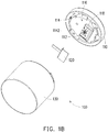
- FIG. 1B shows a schematic three-dimensional exploded view of the blood plasma and blood cell separation device 100 of FIG. 1A from another perspective.
- the blood plasma and blood cell separation device 100 includes a first body 110, a blood plasma separation membrane 120 and a second body 130.
- the first body 110 is movably assembled to the second body 130 and has an injection port 112.
- the second body 130 has a collecting stage 132, and the collecting stage 132 has a collecting surface 133 and a sampling recess 134 on the collecting stage 132.
- the blood plasma separation membrane 120 is disposed on the first body 110 and may move along with the first body 110.
- the first body 110 has a first surface 116 facing the second body 130.
- the first surface 116 is provided with a membrane carrier 118 protruding toward the second body 130, and the injection port 112 is disposed on the membrane carrier 118.
- the second body 130 has a second surface 131 facing the first body 110.
- the collecting stage 132 protrudes from the second surface 131 toward the first body 110.
- the sampling recess 134 is recessed from the collecting surface 133.
- the blood plasma separation membrane 120 is fixed on the membrane carrier 118 of the first body 110 and may face the collecting surface 133 of the collecting stage 132. When the blood plasma separation membrane 120 faces the collecting surface 133, a capillary action may be generated between the blood plasma separation membrane 120 and the collecting surface 133.
- the first body 110 has a first connecting portion 114
- the second body 130 has a second connecting portion 135 movably and detachably connected to the first connecting portion 114.
- the first connecting portion 114 may be a sliding slot 114 that has a disengagement port 1142.
- the second connecting portion 135 may be a bump 135 that moves inside the sliding slot 114 and may move along the sliding slot 114 to the disengagement port 1142 to be detached from the sliding slot 114.
- the blood plasma separation membrane 120 is fixed on the first body 110.
- the first body 110 may carry the blood plasma separation membrane 120 to move relative to the second body 130 so as to make the blood plasma separation membrane 120 and the collecting stage 132 in a first relative position P1 and a second relative position P2 respectively.
- FIG. 1C shows a schematic top view of the blood plasma separation membrane 120 and the collecting stage 132 of FIG. 1A in a first relative position P1.
- FIG. 1D shows a schematic top view of the blood plasma separation membrane 120 and the collecting stage 132 of FIG. 1A in a second relative position P2.
- the blood plasma separation membrane 120 and the collecting surface 133 has a first overlapping surface A1.
- the blood plasma separation membrane 120 and the collecting stage 132 when the blood plasma separation membrane 120 and the collecting stage 132 are in the second relative position P2, the blood plasma separation membrane 120 and the collecting surface 133 has a second overlapping surface A2.
- an area of the second overlapping surface A2 is smaller than an area of the first overlapping surface A1.
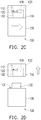
- FIGs. 2A to 2D show schematic front views of a blood plasma and blood cell separating method in an embodiment of the invention.
- FIG. 3A and FIG. 3B show schematic views of blood plasma distribution when the blood plasma separation membrane 120 and the collecting stage 132 are in the first relative position P1 and in the second relative position P2 respectively.
- FIG. 3C shows a schematic top view of the second body 130 of the blood plasma and blood cell separation device 100 of FIG. 2D .
- the blood 10 is, for example, whole blood, i.e. containing blood plasma, blood cells and platelets, and has a volume of 50 microliters (ul), for example.
- an inlet side (i.e. the side closer to the injection port 112) of the blood plasma separation membrane 120 has an aperture of about 100 micrometers
- an outlet side (i.e. the side closer to the collecting stage 132) of the blood plasma separation membrane 120 has an aperture of about 1 micrometer.
- the blood plasma separation membrane 120 and the collecting stage 132 are in the first relative position P1. That is, the blood plasma separation membrane 120 faces the collecting surface 133, and the blood plasma separation membrane 120 and the collecting surface 133 has the first overlapping surface A1, as shown in FIG. 1C .
- a capillary force is generated between the collecting surface 133 of the collecting stage 132 and the blood plasma separation membrane 120 on the first overlapping surface A1 to attract the blood plasma 20 in the blood plasma separation membrane 120 so that the blood plasma 20 is separated from the blood plasma separation membrane 120.
- the blood plasma 20 separated from the blood plasma separation membrane 120 is distributed on the first overlapping surface A1 of the collecting surface 133 of the collecting stage 132.
- the blood plasma 20 distributed on the first overlapping surface A1 of the collecting surface 133 enters in the sampling recess 134 on the collecting stage 132.
- a relative movement such as a relative rotation
- the blood plasma 20 distributed on the first overlapping surface A1 of the collecting surface 133 enters in the sampling recess 134 on the collecting stage 132.
- the area of the overlapping surface between the collecting surface 133 of the collecting stage 132 and the blood plasma separation membrane 120 becomes smaller, so that the area in which the blood plasma 20 may be distributed on the collecting surface 133 becomes smaller correspondingly and is unable to accommodate all of the blood plasma 20 separated from the blood plasma separation membrane 120.
- the excess blood plasma 20 enters in the sampling recess 134 and is accommodated in the sampling recess 134.
- the blood plasma 20 is accommodated in the sampling recess 134 of the second body 130 by the relative movement between the first body 110 and the second body 130.
- the type of the relative movement adopted by the first body and the second body may also be relative slide or other kind of motions, which still falls within the protected scope of this invention.
- the blood plasma separation membrane 120 and the collecting surface 133 has the second overlapping surface A2. Because the second overlapping surface A2 is smaller than the first overlapping surface A1, the blood plasma 20 originally distributed on the first overlapping surface A1 may not be completely distributed on the second overlapping surface A2. Consequently, the excess blood plasma 20 enters in the sampling recess 134.
- first body 110 and the second body 130 are disassembled so as to separate the first body 110 and the second body 130.
- a lancet 30 or a pipette may be used to collect the blood plasma 20 in the sampling recess 134 of the second body 130.
- the first body 110 has the injection port 112 from which the blood 10 is injected and serves the function of fixing the blood plasma separation membrane 120
- the blood plasma separation membrane 120 serves the function of separating the blood plasma 20 from the blood 10
- the second body 130 serves the function of removing the blood plasma 20 from the blood plasma separation membrane 120 and collecting the blood plasma 20.
- the step of applying a prior art absorbent material is not necessary.
- the residual blood plasma is also reduced so as to improve the separation and utilization rate.
- the operation time is also reduced so that the desired sample of the blood plasma 20 may be obtained in an effective and speedy manner.
- the blood plasma and blood cell separating method using the blood plasma and blood cell separation device 100 of this embodiment allows the user to obtain the desired sample of the blood plasma 20 in a short time with only a small amount of whole blood.
- the blood plasma in the blood plasma separation membrane is separated by a capillary force between the collecting stage of the second body and the blood plasma separation membrane, and the blood plasma enters in the sampling recess by the relative movement between the first body and the second body.
- the user simply needs to rotate and disassemble the first body and the second body to obtain the desired sample of the blood plasma.
- the blood plasma and blood cell separation device of the invention obtains the desired sample of the blood plasma in an effective and speedy manner, while the blood plasma and blood cell separating method using the blood plasma and blood cell separation device of the invention allows the user to obtain the desired sample of the blood plasma in a short time with only a small amount of whole blood.
Landscapes
- Health & Medical Sciences (AREA)
- Chemical & Material Sciences (AREA)
- Engineering & Computer Science (AREA)
- Life Sciences & Earth Sciences (AREA)
- Chemical Kinetics & Catalysis (AREA)
- Water Supply & Treatment (AREA)
- Hematology (AREA)
- Biomedical Technology (AREA)
- Analytical Chemistry (AREA)
- General Health & Medical Sciences (AREA)
- Physics & Mathematics (AREA)
- Molecular Biology (AREA)
- Clinical Laboratory Science (AREA)
- Pathology (AREA)
- Biochemistry (AREA)
- General Physics & Mathematics (AREA)
- Immunology (AREA)
- Medicinal Chemistry (AREA)
- Food Science & Technology (AREA)
- Urology & Nephrology (AREA)
- Biophysics (AREA)
- Ecology (AREA)
- Dispersion Chemistry (AREA)
- Investigating Or Analysing Biological Materials (AREA)
- Sampling And Sample Adjustment (AREA)
- Separation Using Semi-Permeable Membranes (AREA)
Applications Claiming Priority (1)
| Application Number | Priority Date | Filing Date | Title |
|---|---|---|---|
| CN201710270473.7A CN108732001B (zh) | 2017-04-24 | 2017-04-24 | 血浆血球分离装置及其分离方法 |
Publications (2)
| Publication Number | Publication Date |
|---|---|
| EP3395431A1 true EP3395431A1 (fr) | 2018-10-31 |
| EP3395431B1 EP3395431B1 (fr) | 2020-10-07 |
Family
ID=59772367
Family Applications (1)
| Application Number | Title | Priority Date | Filing Date |
|---|---|---|---|
| EP17186153.7A Active EP3395431B1 (fr) | 2017-04-24 | 2017-08-14 | Dispositif de séparation de plasma sanguin et cellules sanguines et procédé de séparation |
Country Status (4)
| Country | Link |
|---|---|
| US (1) | US10589271B2 (fr) |
| EP (1) | EP3395431B1 (fr) |
| JP (1) | JP6657151B2 (fr) |
| CN (1) | CN108732001B (fr) |
Families Citing this family (3)
| Publication number | Priority date | Publication date | Assignee | Title |
|---|---|---|---|---|
| MX2021006612A (es) | 2018-12-07 | 2021-07-07 | Siemens Healthcare Diagnostics Inc | Dispositivo de recoleccion de solucion con elemento de evaluacion. |
| JP7361198B2 (ja) | 2019-07-19 | 2023-10-13 | シーメンス・ヘルスケア・ダイアグノスティックス・インコーポレイテッド | 接線流溶血検出血液検査装置 |
| WO2024197363A1 (fr) * | 2023-03-29 | 2024-10-03 | The University Of Western Australia | Dispositif de collecte de plasma |
Citations (6)
| Publication number | Priority date | Publication date | Assignee | Title |
|---|---|---|---|---|
| US20120024788A1 (en) * | 2010-07-27 | 2012-02-02 | Northwestern University | Devices and methods for filtering blood plasma |
| WO2012103511A2 (fr) * | 2011-01-27 | 2012-08-02 | Invisible Sentinel, Inc. | Dispositifs de détection d'analytes, dispositifs multiplexes et de paillasse pour la détection d'analytes, et utilisations de ceux-ci |
| US20160029936A1 (en) * | 2014-08-04 | 2016-02-04 | General Electric Company | Device for separation and collection of plasma |
| WO2016073415A2 (fr) * | 2014-11-04 | 2016-05-12 | Wainamics, Inc. | Séparateur de plasma à l'échelle microscopique |
| US20160274010A1 (en) * | 2013-12-03 | 2016-09-22 | The University Of Tokyo | Separation unit, separation method, fluid device, and composite fluid device and kit |
| WO2017015243A1 (fr) * | 2015-07-21 | 2017-01-26 | Mcneely Michael Ryan | Séparation et dosage automatiques du plasma |
Family Cites Families (5)
| Publication number | Priority date | Publication date | Assignee | Title |
|---|---|---|---|---|
| JP5213432B2 (ja) * | 2007-12-20 | 2013-06-19 | パナソニック株式会社 | 生体分析用デバイスおよびそれを用いた血液分離方法 |
| JP5138658B2 (ja) * | 2009-10-26 | 2013-02-06 | Dicプラスチック株式会社 | 免疫測定器具及び免疫測定方法 |
| BR112013022568B1 (pt) * | 2011-03-11 | 2021-01-12 | Fenwal, Inc. | método para umedecer uma membrana em um separador de membrana |
| TW201500096A (zh) * | 2013-06-19 | 2015-01-01 | Anatech Co Ltd | 血球血漿分離裝置 |
| CN105980846B (zh) * | 2014-02-21 | 2018-12-07 | 宝生物工程美国有限公司 | 包括聚(酸)膜分离基质的旋转柱及其制造和使用的方法 |
-
2017
- 2017-04-24 CN CN201710270473.7A patent/CN108732001B/zh not_active Expired - Fee Related
- 2017-07-12 US US15/647,273 patent/US10589271B2/en active Active
- 2017-08-14 EP EP17186153.7A patent/EP3395431B1/fr active Active
- 2017-08-22 JP JP2017159029A patent/JP6657151B2/ja active Active
Patent Citations (6)
| Publication number | Priority date | Publication date | Assignee | Title |
|---|---|---|---|---|
| US20120024788A1 (en) * | 2010-07-27 | 2012-02-02 | Northwestern University | Devices and methods for filtering blood plasma |
| WO2012103511A2 (fr) * | 2011-01-27 | 2012-08-02 | Invisible Sentinel, Inc. | Dispositifs de détection d'analytes, dispositifs multiplexes et de paillasse pour la détection d'analytes, et utilisations de ceux-ci |
| US20160274010A1 (en) * | 2013-12-03 | 2016-09-22 | The University Of Tokyo | Separation unit, separation method, fluid device, and composite fluid device and kit |
| US20160029936A1 (en) * | 2014-08-04 | 2016-02-04 | General Electric Company | Device for separation and collection of plasma |
| WO2016073415A2 (fr) * | 2014-11-04 | 2016-05-12 | Wainamics, Inc. | Séparateur de plasma à l'échelle microscopique |
| WO2017015243A1 (fr) * | 2015-07-21 | 2017-01-26 | Mcneely Michael Ryan | Séparation et dosage automatiques du plasma |
Also Published As
| Publication number | Publication date |
|---|---|
| JP6657151B2 (ja) | 2020-03-04 |
| JP2018185283A (ja) | 2018-11-22 |
| US20180304261A1 (en) | 2018-10-25 |
| US10589271B2 (en) | 2020-03-17 |
| CN108732001A (zh) | 2018-11-02 |
| CN108732001B (zh) | 2021-03-05 |
| EP3395431B1 (fr) | 2020-10-07 |
Similar Documents
| Publication | Publication Date | Title |
|---|---|---|
| US10111610B2 (en) | Microscale plasma separator | |
| US9873117B2 (en) | Biological fluid micro-sample management device | |
| RU2645091C2 (ru) | Способ и устройство для отделения плазмы от крови для оценки содержания билирубина | |
| EP3395431B1 (fr) | Dispositif de séparation de plasma sanguin et cellules sanguines et procédé de séparation | |
| EP2986382B1 (fr) | Dispositif de enlevement, transfert et de séparation d'échantillon sanguin | |
| JP2020523574A (ja) | 生物学的流体分離デバイス | |
| US8470259B2 (en) | Method and device for particle removal and droplet preparation for qualitative and quantitative bioanalysis | |
| WO2019025914A1 (fr) | Dispositif de séparation de plasma | |
| JP6357473B2 (ja) | 一滴の血液を使用した血漿分離 | |
| JP2004184099A (ja) | 採血用具 | |
| EP2889024A1 (fr) | Poche de sang et système de poche de sang la comprenant | |
| TWI627991B (zh) | 自驅式微流體過濾裝置、微流體過濾裝置及微流體驅動裝置 | |
| WO2024064917A1 (fr) | Système de biopsie aphérétique comprenant un dispositif microfluidique | |
| TWI644691B (zh) | 血漿血球分離裝置及其分離方法 | |
| EP3803389B1 (fr) | Dispositif de séparation de fluide biologique | |
| US20100240119A1 (en) | Microseparation structure and devices formed therewith |
Legal Events
| Date | Code | Title | Description |
|---|---|---|---|
| PUAI | Public reference made under article 153(3) epc to a published international application that has entered the european phase |
Free format text: ORIGINAL CODE: 0009012 |
|
| STAA | Information on the status of an ep patent application or granted ep patent |
Free format text: STATUS: REQUEST FOR EXAMINATION WAS MADE |
|
| 17P | Request for examination filed |
Effective date: 20180222 |
|
| AK | Designated contracting states |
Kind code of ref document: A1 Designated state(s): AL AT BE BG CH CY CZ DE DK EE ES FI FR GB GR HR HU IE IS IT LI LT LU LV MC MK MT NL NO PL PT RO RS SE SI SK SM TR |
|
| AX | Request for extension of the european patent |
Extension state: BA ME |
|
| RBV | Designated contracting states (corrected) |
Designated state(s): AL AT BE BG CH CY CZ DE DK EE ES FI FR GB GR HR HU IE IS IT LI LT LU LV MC MK MT NL NO PL PT RO RS SE SI SK SM TR |
|
| RIC1 | Information provided on ipc code assigned before grant |
Ipc: B01D 61/18 20060101ALI20200311BHEP Ipc: B01D 61/14 20060101AFI20200311BHEP Ipc: B01D 63/08 20060101ALI20200311BHEP Ipc: B01L 3/00 20060101ALI20200311BHEP Ipc: G01N 33/49 20060101ALI20200311BHEP |
|
| GRAP | Despatch of communication of intention to grant a patent |
Free format text: ORIGINAL CODE: EPIDOSNIGR1 |
|
| STAA | Information on the status of an ep patent application or granted ep patent |
Free format text: STATUS: GRANT OF PATENT IS INTENDED |
|
| INTG | Intention to grant announced |
Effective date: 20200430 |
|
| GRAS | Grant fee paid |
Free format text: ORIGINAL CODE: EPIDOSNIGR3 |
|
| GRAF | Information related to payment of grant fee modified |
Free format text: ORIGINAL CODE: EPIDOSCIGR3 |
|
| GRAA | (expected) grant |
Free format text: ORIGINAL CODE: 0009210 |
|
| STAA | Information on the status of an ep patent application or granted ep patent |
Free format text: STATUS: THE PATENT HAS BEEN GRANTED |
|
| AK | Designated contracting states |
Kind code of ref document: B1 Designated state(s): AL AT BE BG CH CY CZ DE DK EE ES FI FR GB GR HR HU IE IS IT LI LT LU LV MC MK MT NL NO PL PT RO RS SE SI SK SM TR |
|
| REG | Reference to a national code |
Ref country code: GB Ref legal event code: FG4D |
|
| REG | Reference to a national code |
Ref country code: CH Ref legal event code: EP Ref country code: CH Ref legal event code: NV Representative=s name: BUGNION S.A., CH Ref country code: AT Ref legal event code: REF Ref document number: 1320553 Country of ref document: AT Kind code of ref document: T Effective date: 20201015 |
|
| REG | Reference to a national code |
Ref country code: IE Ref legal event code: FG4D |
|
| REG | Reference to a national code |
Ref country code: DE Ref legal event code: R096 Ref document number: 602017024906 Country of ref document: DE |
|
| REG | Reference to a national code |
Ref country code: NL Ref legal event code: MP Effective date: 20201007 |
|
| REG | Reference to a national code |
Ref country code: AT Ref legal event code: MK05 Ref document number: 1320553 Country of ref document: AT Kind code of ref document: T Effective date: 20201007 |
|
| PG25 | Lapsed in a contracting state [announced via postgrant information from national office to epo] |
Ref country code: NO Free format text: LAPSE BECAUSE OF FAILURE TO SUBMIT A TRANSLATION OF THE DESCRIPTION OR TO PAY THE FEE WITHIN THE PRESCRIBED TIME-LIMIT Effective date: 20210107 Ref country code: RS Free format text: LAPSE BECAUSE OF FAILURE TO SUBMIT A TRANSLATION OF THE DESCRIPTION OR TO PAY THE FEE WITHIN THE PRESCRIBED TIME-LIMIT Effective date: 20201007 Ref country code: PT Free format text: LAPSE BECAUSE OF FAILURE TO SUBMIT A TRANSLATION OF THE DESCRIPTION OR TO PAY THE FEE WITHIN THE PRESCRIBED TIME-LIMIT Effective date: 20210208 Ref country code: GR Free format text: LAPSE BECAUSE OF FAILURE TO SUBMIT A TRANSLATION OF THE DESCRIPTION OR TO PAY THE FEE WITHIN THE PRESCRIBED TIME-LIMIT Effective date: 20210108 Ref country code: FI Free format text: LAPSE BECAUSE OF FAILURE TO SUBMIT A TRANSLATION OF THE DESCRIPTION OR TO PAY THE FEE WITHIN THE PRESCRIBED TIME-LIMIT Effective date: 20201007 |
|
| REG | Reference to a national code |
Ref country code: LT Ref legal event code: MG4D |
|
| PG25 | Lapsed in a contracting state [announced via postgrant information from national office to epo] |
Ref country code: AT Free format text: LAPSE BECAUSE OF FAILURE TO SUBMIT A TRANSLATION OF THE DESCRIPTION OR TO PAY THE FEE WITHIN THE PRESCRIBED TIME-LIMIT Effective date: 20201007 Ref country code: ES Free format text: LAPSE BECAUSE OF FAILURE TO SUBMIT A TRANSLATION OF THE DESCRIPTION OR TO PAY THE FEE WITHIN THE PRESCRIBED TIME-LIMIT Effective date: 20201007 Ref country code: BG Free format text: LAPSE BECAUSE OF FAILURE TO SUBMIT A TRANSLATION OF THE DESCRIPTION OR TO PAY THE FEE WITHIN THE PRESCRIBED TIME-LIMIT Effective date: 20210107 Ref country code: IS Free format text: LAPSE BECAUSE OF FAILURE TO SUBMIT A TRANSLATION OF THE DESCRIPTION OR TO PAY THE FEE WITHIN THE PRESCRIBED TIME-LIMIT Effective date: 20210207 Ref country code: LV Free format text: LAPSE BECAUSE OF FAILURE TO SUBMIT A TRANSLATION OF THE DESCRIPTION OR TO PAY THE FEE WITHIN THE PRESCRIBED TIME-LIMIT Effective date: 20201007 Ref country code: PL Free format text: LAPSE BECAUSE OF FAILURE TO SUBMIT A TRANSLATION OF THE DESCRIPTION OR TO PAY THE FEE WITHIN THE PRESCRIBED TIME-LIMIT Effective date: 20201007 Ref country code: SE Free format text: LAPSE BECAUSE OF FAILURE TO SUBMIT A TRANSLATION OF THE DESCRIPTION OR TO PAY THE FEE WITHIN THE PRESCRIBED TIME-LIMIT Effective date: 20201007 |
|
| PG25 | Lapsed in a contracting state [announced via postgrant information from national office to epo] |
Ref country code: HR Free format text: LAPSE BECAUSE OF FAILURE TO SUBMIT A TRANSLATION OF THE DESCRIPTION OR TO PAY THE FEE WITHIN THE PRESCRIBED TIME-LIMIT Effective date: 20201007 Ref country code: NL Free format text: LAPSE BECAUSE OF FAILURE TO SUBMIT A TRANSLATION OF THE DESCRIPTION OR TO PAY THE FEE WITHIN THE PRESCRIBED TIME-LIMIT Effective date: 20201007 |
|
| REG | Reference to a national code |
Ref country code: DE Ref legal event code: R097 Ref document number: 602017024906 Country of ref document: DE |
|
| PG25 | Lapsed in a contracting state [announced via postgrant information from national office to epo] |
Ref country code: CZ Free format text: LAPSE BECAUSE OF FAILURE TO SUBMIT A TRANSLATION OF THE DESCRIPTION OR TO PAY THE FEE WITHIN THE PRESCRIBED TIME-LIMIT Effective date: 20201007 Ref country code: EE Free format text: LAPSE BECAUSE OF FAILURE TO SUBMIT A TRANSLATION OF THE DESCRIPTION OR TO PAY THE FEE WITHIN THE PRESCRIBED TIME-LIMIT Effective date: 20201007 Ref country code: SM Free format text: LAPSE BECAUSE OF FAILURE TO SUBMIT A TRANSLATION OF THE DESCRIPTION OR TO PAY THE FEE WITHIN THE PRESCRIBED TIME-LIMIT Effective date: 20201007 Ref country code: LT Free format text: LAPSE BECAUSE OF FAILURE TO SUBMIT A TRANSLATION OF THE DESCRIPTION OR TO PAY THE FEE WITHIN THE PRESCRIBED TIME-LIMIT Effective date: 20201007 Ref country code: RO Free format text: LAPSE BECAUSE OF FAILURE TO SUBMIT A TRANSLATION OF THE DESCRIPTION OR TO PAY THE FEE WITHIN THE PRESCRIBED TIME-LIMIT Effective date: 20201007 Ref country code: SK Free format text: LAPSE BECAUSE OF FAILURE TO SUBMIT A TRANSLATION OF THE DESCRIPTION OR TO PAY THE FEE WITHIN THE PRESCRIBED TIME-LIMIT Effective date: 20201007 |
|
| PLBE | No opposition filed within time limit |
Free format text: ORIGINAL CODE: 0009261 |
|
| STAA | Information on the status of an ep patent application or granted ep patent |
Free format text: STATUS: NO OPPOSITION FILED WITHIN TIME LIMIT |
|
| PG25 | Lapsed in a contracting state [announced via postgrant information from national office to epo] |
Ref country code: DK Free format text: LAPSE BECAUSE OF FAILURE TO SUBMIT A TRANSLATION OF THE DESCRIPTION OR TO PAY THE FEE WITHIN THE PRESCRIBED TIME-LIMIT Effective date: 20201007 |
|
| 26N | No opposition filed |
Effective date: 20210708 |
|
| PG25 | Lapsed in a contracting state [announced via postgrant information from national office to epo] |
Ref country code: AL Free format text: LAPSE BECAUSE OF FAILURE TO SUBMIT A TRANSLATION OF THE DESCRIPTION OR TO PAY THE FEE WITHIN THE PRESCRIBED TIME-LIMIT Effective date: 20201007 |
|
| PG25 | Lapsed in a contracting state [announced via postgrant information from national office to epo] |
Ref country code: SI Free format text: LAPSE BECAUSE OF FAILURE TO SUBMIT A TRANSLATION OF THE DESCRIPTION OR TO PAY THE FEE WITHIN THE PRESCRIBED TIME-LIMIT Effective date: 20201007 |
|
| PG25 | Lapsed in a contracting state [announced via postgrant information from national office to epo] |
Ref country code: MC Free format text: LAPSE BECAUSE OF FAILURE TO SUBMIT A TRANSLATION OF THE DESCRIPTION OR TO PAY THE FEE WITHIN THE PRESCRIBED TIME-LIMIT Effective date: 20201007 |
|
| REG | Reference to a national code |
Ref country code: BE Ref legal event code: MM Effective date: 20210831 |
|
| PG25 | Lapsed in a contracting state [announced via postgrant information from national office to epo] |
Ref country code: IS Free format text: LAPSE BECAUSE OF FAILURE TO SUBMIT A TRANSLATION OF THE DESCRIPTION OR TO PAY THE FEE WITHIN THE PRESCRIBED TIME-LIMIT Effective date: 20210207 Ref country code: LU Free format text: LAPSE BECAUSE OF NON-PAYMENT OF DUE FEES Effective date: 20210814 |
|
| PG25 | Lapsed in a contracting state [announced via postgrant information from national office to epo] |
Ref country code: IE Free format text: LAPSE BECAUSE OF NON-PAYMENT OF DUE FEES Effective date: 20210814 Ref country code: BE Free format text: LAPSE BECAUSE OF NON-PAYMENT OF DUE FEES Effective date: 20210831 |
|
| PG25 | Lapsed in a contracting state [announced via postgrant information from national office to epo] |
Ref country code: CY Free format text: LAPSE BECAUSE OF FAILURE TO SUBMIT A TRANSLATION OF THE DESCRIPTION OR TO PAY THE FEE WITHIN THE PRESCRIBED TIME-LIMIT Effective date: 20201007 |
|
| PG25 | Lapsed in a contracting state [announced via postgrant information from national office to epo] |
Ref country code: HU Free format text: LAPSE BECAUSE OF FAILURE TO SUBMIT A TRANSLATION OF THE DESCRIPTION OR TO PAY THE FEE WITHIN THE PRESCRIBED TIME-LIMIT; INVALID AB INITIO Effective date: 20170814 |
|
| PG25 | Lapsed in a contracting state [announced via postgrant information from national office to epo] |
Ref country code: MK Free format text: LAPSE BECAUSE OF FAILURE TO SUBMIT A TRANSLATION OF THE DESCRIPTION OR TO PAY THE FEE WITHIN THE PRESCRIBED TIME-LIMIT Effective date: 20201007 |
|
| PG25 | Lapsed in a contracting state [announced via postgrant information from national office to epo] |
Ref country code: TR Free format text: LAPSE BECAUSE OF FAILURE TO SUBMIT A TRANSLATION OF THE DESCRIPTION OR TO PAY THE FEE WITHIN THE PRESCRIBED TIME-LIMIT Effective date: 20201007 |
|
| PG25 | Lapsed in a contracting state [announced via postgrant information from national office to epo] |
Ref country code: MT Free format text: LAPSE BECAUSE OF FAILURE TO SUBMIT A TRANSLATION OF THE DESCRIPTION OR TO PAY THE FEE WITHIN THE PRESCRIBED TIME-LIMIT Effective date: 20201007 |
|
| PGFP | Annual fee paid to national office [announced via postgrant information from national office to epo] |
Ref country code: GB Payment date: 20250612 Year of fee payment: 9 |
|
| PGFP | Annual fee paid to national office [announced via postgrant information from national office to epo] |
Ref country code: FR Payment date: 20250612 Year of fee payment: 9 |
|
| PGFP | Annual fee paid to national office [announced via postgrant information from national office to epo] |
Ref country code: DE Payment date: 20250605 Year of fee payment: 9 |
|
| PGFP | Annual fee paid to national office [announced via postgrant information from national office to epo] |
Ref country code: IT Payment date: 20250821 Year of fee payment: 9 |
|
| PGFP | Annual fee paid to national office [announced via postgrant information from national office to epo] |
Ref country code: CH Payment date: 20250901 Year of fee payment: 9 |