EP3395626B1 - Teleskopreinigungsvorrichtung - Google Patents
Teleskopreinigungsvorrichtung Download PDFInfo
- Publication number
- EP3395626B1 EP3395626B1 EP18167190.0A EP18167190A EP3395626B1 EP 3395626 B1 EP3395626 B1 EP 3395626B1 EP 18167190 A EP18167190 A EP 18167190A EP 3395626 B1 EP3395626 B1 EP 3395626B1
- Authority
- EP
- European Patent Office
- Prior art keywords
- cleaning device
- rod
- fluid
- movable piston
- distribution
- Prior art date
- Legal status (The legal status is an assumption and is not a legal conclusion. Google has not performed a legal analysis and makes no representation as to the accuracy of the status listed.)
- Active
Links
Images

Classifications
-
- B—PERFORMING OPERATIONS; TRANSPORTING
- B60—VEHICLES IN GENERAL
- B60S—SERVICING, CLEANING, REPAIRING, SUPPORTING, LIFTING, OR MANOEUVRING OF VEHICLES, NOT OTHERWISE PROVIDED FOR
- B60S1/00—Cleaning of vehicles
- B60S1/02—Cleaning windscreens, windows or optical devices
- B60S1/56—Cleaning windscreens, windows or optical devices specially adapted for cleaning other parts or devices than front windows or windscreens
-
- B—PERFORMING OPERATIONS; TRANSPORTING
- B08—CLEANING
- B08B—CLEANING IN GENERAL; PREVENTION OF FOULING IN GENERAL
- B08B3/00—Cleaning by methods involving the use or presence of liquid or steam
- B08B3/02—Cleaning by the force of jets or sprays
-
- B—PERFORMING OPERATIONS; TRANSPORTING
- B08—CLEANING
- B08B—CLEANING IN GENERAL; PREVENTION OF FOULING IN GENERAL
- B08B3/00—Cleaning by methods involving the use or presence of liquid or steam
- B08B3/04—Cleaning involving contact with liquid
- B08B3/10—Cleaning involving contact with liquid with additional treatment of the liquid or of the object being cleaned, e.g. by heat, by electricity or by vibration
-
- B—PERFORMING OPERATIONS; TRANSPORTING
- B60—VEHICLES IN GENERAL
- B60S—SERVICING, CLEANING, REPAIRING, SUPPORTING, LIFTING, OR MANOEUVRING OF VEHICLES, NOT OTHERWISE PROVIDED FOR
- B60S1/00—Cleaning of vehicles
- B60S1/02—Cleaning windscreens, windows or optical devices
- B60S1/46—Cleaning windscreens, windows or optical devices using liquid; Windscreen washers
-
- B—PERFORMING OPERATIONS; TRANSPORTING
- B60—VEHICLES IN GENERAL
- B60S—SERVICING, CLEANING, REPAIRING, SUPPORTING, LIFTING, OR MANOEUVRING OF VEHICLES, NOT OTHERWISE PROVIDED FOR
- B60S1/00—Cleaning of vehicles
- B60S1/02—Cleaning windscreens, windows or optical devices
- B60S1/46—Cleaning windscreens, windows or optical devices using liquid; Windscreen washers
- B60S1/48—Liquid supply therefor
- B60S1/487—Liquid supply therefor the liquid being heated
- B60S1/488—Liquid supply therefor the liquid being heated electrically
-
- B—PERFORMING OPERATIONS; TRANSPORTING
- B60—VEHICLES IN GENERAL
- B60S—SERVICING, CLEANING, REPAIRING, SUPPORTING, LIFTING, OR MANOEUVRING OF VEHICLES, NOT OTHERWISE PROVIDED FOR
- B60S1/00—Cleaning of vehicles
- B60S1/02—Cleaning windscreens, windows or optical devices
- B60S1/46—Cleaning windscreens, windows or optical devices using liquid; Windscreen washers
- B60S1/48—Liquid supply therefor
- B60S1/52—Arrangement of nozzles; Liquid spreading means
-
- B—PERFORMING OPERATIONS; TRANSPORTING
- B60—VEHICLES IN GENERAL
- B60S—SERVICING, CLEANING, REPAIRING, SUPPORTING, LIFTING, OR MANOEUVRING OF VEHICLES, NOT OTHERWISE PROVIDED FOR
- B60S1/00—Cleaning of vehicles
- B60S1/02—Cleaning windscreens, windows or optical devices
- B60S1/46—Cleaning windscreens, windows or optical devices using liquid; Windscreen washers
- B60S1/48—Liquid supply therefor
- B60S1/52—Arrangement of nozzles; Liquid spreading means
- B60S1/522—Arrangement of nozzles; Liquid spreading means moving liquid spreading means, e.g. arranged in wiper arms
- B60S1/528—Arrangement of nozzles; Liquid spreading means moving liquid spreading means, e.g. arranged in wiper arms the spreading means being moved between a rest position and a working position
-
- B—PERFORMING OPERATIONS; TRANSPORTING
- B60—VEHICLES IN GENERAL
- B60S—SERVICING, CLEANING, REPAIRING, SUPPORTING, LIFTING, OR MANOEUVRING OF VEHICLES, NOT OTHERWISE PROVIDED FOR
- B60S1/00—Cleaning of vehicles
- B60S1/02—Cleaning windscreens, windows or optical devices
- B60S1/54—Cleaning windscreens, windows or optical devices using gas, e.g. hot air
-
- G—PHYSICS
- G01—MEASURING; TESTING
- G01S—RADIO DIRECTION-FINDING; RADIO NAVIGATION; DETERMINING DISTANCE OR VELOCITY BY USE OF RADIO WAVES; LOCATING OR PRESENCE-DETECTING BY USE OF THE REFLECTION OR RERADIATION OF RADIO WAVES; ANALOGOUS ARRANGEMENTS USING OTHER WAVES
- G01S17/00—Systems using the reflection or reradiation of electromagnetic waves other than radio waves, e.g. lidar systems
- G01S17/88—Lidar systems specially adapted for specific applications
- G01S17/93—Lidar systems specially adapted for specific applications for anti-collision purposes
- G01S17/931—Lidar systems specially adapted for specific applications for anti-collision purposes of land vehicles
-
- B—PERFORMING OPERATIONS; TRANSPORTING
- B08—CLEANING
- B08B—CLEANING IN GENERAL; PREVENTION OF FOULING IN GENERAL
- B08B2203/00—Details of cleaning machines or methods involving the use or presence of liquid or steam
- B08B2203/007—Heating the liquid
-
- B—PERFORMING OPERATIONS; TRANSPORTING
- B60—VEHICLES IN GENERAL
- B60Y—INDEXING SCHEME RELATING TO ASPECTS CROSS-CUTTING VEHICLE TECHNOLOGY
- B60Y2400/00—Special features of vehicle units
- B60Y2400/30—Sensors
-
- G—PHYSICS
- G01—MEASURING; TESTING
- G01S—RADIO DIRECTION-FINDING; RADIO NAVIGATION; DETERMINING DISTANCE OR VELOCITY BY USE OF RADIO WAVES; LOCATING OR PRESENCE-DETECTING BY USE OF THE REFLECTION OR RERADIATION OF RADIO WAVES; ANALOGOUS ARRANGEMENTS USING OTHER WAVES
- G01S7/00—Details of systems according to groups G01S13/00, G01S15/00, G01S17/00
- G01S7/48—Details of systems according to groups G01S13/00, G01S15/00, G01S17/00 of systems according to group G01S17/00
- G01S7/497—Means for monitoring or calibrating
- G01S2007/4975—Means for monitoring or calibrating of sensor obstruction by, e.g. dirt- or ice-coating, e.g. by reflection measurement on front-screen
- G01S2007/4977—Means for monitoring or calibrating of sensor obstruction by, e.g. dirt- or ice-coating, e.g. by reflection measurement on front-screen including means to prevent or remove the obstruction
Definitions
- the present invention relates to the field of optical detection systems intended to equip a motor vehicle. It relates more particularly to cleaning devices intended to project at least one cleaning or drying fluid towards an optical surface to be cleaned of an optical sensor of such a detection system.
- An optical detection system is any system comprising optical sensors such as cameras, laser sensors or other sensors based on the emission and/or detection of light in the spectrum visible or invisible to humans, in particular infrared.
- a cleaning device can be controlled to project, onto an optical surface of a sensor of the optical detection system (for example the lens of a camera), one or more cleaning and/or drying fluids before the detection (for example the shooting) is carried out.
- cleaning devices can comprise at least one fluid conveying body formed of a movable part, consisting of a piston housed in a jack cylinder, and capable of moving from a retracted rest position to a deployed cleaning position.
- the conveying body is usually connected, at its upstream end, and by means of a flexible supply conduit, to a storage tank for the cleaning and/or drying fluid(s), and connected at its downstream end, opposite its upstream end, to a device for distributing and projecting the cleaning and/or drying fluid(s).
- the invention falls within this context and aims to propose an improvement to existing solutions relating to cleaning devices by spraying a heated cleaning fluid onto an optical surface to be cleaned.
- the invention thus aims to propose a cleaning device intended to spray at least one fluid onto a surface to be cleaned of a motor vehicle, such as an optical surface of an optical sensor of an optical detection system which, by means of a compact and telescopic arrangement, makes it possible not to hinder the operation of the optical sensor and which, by means of the arrangement of a heating device, makes it possible to increase the cleaning power of the sprayed fluid, such that the efficiency of cleaning and defrosting of the optical surface to be cleaned are improved.
- the first subject of the invention is a telescopic cleaning device intended to project at least one cleaning and/or drying fluid towards a glass surface to be cleaned of a motor vehicle, such as an optical surface of an optical sensor of an optical detection system for a vehicle, said cleaning device comprising at least one hollow body for conveying cleaning fluid, closed at an upstream end by a flange inlet and housing a movable piston configured to slide in the hollow conveying body, parallel to an axis of elongation of the hollow body, the movable piston, hollowed out by an internal distribution conduit, carrying at a downstream end a fluid distribution element.
- the hollow conveying body further houses a rod which projects from the inlet flange along the elongation axis and around which the movable piston is capable of sliding, the movable piston and the rod being configured to allow between them, depending on the position of the movable piston relative to the rod, the flow of fluid from the inlet flange to the distribution element, and a heating device is provided on the rod, said heating device comprising at least one heating element extending inside a heat-conducting tube, along the elongation axis.
- glazed surface or optical surface
- a second subject of the invention relates to an optical detection system intended to equip a motor vehicle and comprising at least one optical sensor provided with an optical surface, the detection system being particular in that it comprises a telescopic cleaning device as described above, intended to project at least one cleaning and/or drying fluid towards the optical surface.
- the cleaning device comprises at least one rod equipped with a heating device and it may, if necessary, comprise a fluid distribution ramp equipped with an additional heating device independent of the first heating device.
- the optical detection system may comprise, upstream of the heating cleaning device according to the invention, a heating conduit for conveying fluid inside which extends a resistive wire connected to a connector.
- a third subject of the invention relates to a motor vehicle equipped with at least one optical detection system equipped with a cleaning device as previously described, intended to project at least one cleaning and/or drying fluid towards a glazed surface to be cleaned of a motor vehicle, such as an optical surface of an optical sensor.
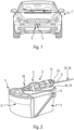
- FIG. 1 illustrates a vehicle 1 comprising according to the invention a detection assembly forming part of a driving assistance system, this detection assembly comprising here on the front face of the vehicle 1 an optical sensor 2 and a cleaning device 3 according to the invention.
- the detection assembly is here arranged on the front face of the vehicle, in particular at the level of the grille.
- FIG. 2 illustrates the cleaning device 3, arranged in the vicinity of the optical sensor 2 and its optical surface 2' and which notably comprises a fluid distribution element 4, here consisting of a distribution ramp, fixed, by an end portion 45, to a downstream end of a hollow conveying body 5 which has an elongated shape along an elongation axis X, the hollow conveying body 5 being fixed to a housing 6 of the optical sensor 2.
- a fluid distribution element 4 here consisting of a distribution ramp
- the telescopic cleaning device 3 is essentially constituted, from upstream to downstream along a longitudinal axis (X) of elongation of the cleaning device 3, of a fluid inlet nozzle 10, an inlet flange 12, a rod 14 secured to the inlet flange 12, the movable piston 8, an elastic return means in position 16 and the distribution element 4 visible on the figure 2 .
- Each of these components is positioned relative to the hollow fluid conveying body 5, of revolution around the elongation axis (X).
- the hollow fluid conveying body 5 is closed at an upstream end by the inlet flange 12 and it is configured to house the movable piston 8, guided in translation along the elongation axis in particular at the level of a guide sleeve 18 formed in the hollow conveying body 5 at the downstream end.
- the fluid inlet nozzle 10 is formed as a projection from the inlet flange 12, and it extends away from the hollow conveying body. 5, here being eccentric relative to the longitudinal axis (X) of the hollow fluid conveying body 5.
- the inlet nozzle 10 has a longitudinal bore passing through and opening inside the hollow body 5 into an inlet chamber 20 delimited at least in part by the inlet flange 12, a peripheral wall of the hollow conveying body 5 and by the movable piston 8.
- the inlet flange 12 is configured to close the upstream end of the hollow fluid conveying body 5.
- a sealing member may be provided at this closure.
- the inlet flange is configured to support the rod 14 on its internal face, facing towards the inside of the hollow fluid conveying body 5.
- the rod 14 extends in projection from the inlet flange 12, inside the hollow fluid conveying body 5, so as on the one hand to form a translational guide member for the movable piston 8, which is configured to slide around this rod 14, and on the other hand to form a part of the translational drive device for the movable piston under the effect of the pressure of the cleaning fluid injected into the hollow conveying body via the fluid inlet nozzle 10.
- the operation of the telescopic cleaning device according to the invention will be described below.
- the heating device 22 comprises in particular a heating element 24 and a hollow cylindrical heat-conducting tube 26 extending along the elongation axis X, the heating element 24 being housed inside the hollow cylindrical heat-conducting tube 26.
- the heating element has in the example illustrated the shape of a resistive wire, without this being limiting of the invention therefore. that the heating element is housed, at least partially, inside the heat-conducting tube.
- the heat conducting tube 26 defines the outer casing of the rod 14, and the fluid caused to flow between the rod and the movable piston, when the cleaning fluid pressure present in the hollow conveying body is sufficient to move the movable piston against the restoring force of the elastic means 16, flows directly against the wall of the heat conducting tube, such that the heat released at the wall of the tube under the effect of the ignition of the heating element 24 is transmitted directly to the cleaning fluid passing through the movable piston in the direction of the distribution element 4.
- the end piece 30 has a peripheral groove 34 capable of accommodating a sealing O-ring 36 so as to allow the sealed sliding of the piston 8 along said rod 14 which it surrounds.
- the sealing O-ring 36 is configured to bear against an internal face of the movable piston 8.
- the movable piston 8 comprises, in the vicinity of its upstream end facing the inlet flange 12, a crown 38 on the outer wall of which is arranged a peripheral groove 40, capable of receiving a sealing element 42 so as to allow the sealed sliding of the movable piston 8 in the hollow body 5 for conveying fluid, and thus to ensure the circulation of the fluid towards the inside of the movable piston 8, between the latter and the rod 14.
- the sealing element 42 is preferably a lip seal, capable of limiting the friction of the movable piston 8 in the hollow body 5.
- the movable piston 8 comprises substantially cylindrical portions which can be defined, from upstream to downstream, as being an intake part 44 carrying the crown 38, a central part 46 capable of sliding within the hollow guide sleeve 18 formed at the downstream end of the hollow conveying body 5 and a terminal distribution part 48, of smaller diameter.
- the movable piston 8 is hollowed out by an internal distribution conduit 50 for the cleaning fluid comprising, at its upstream end, an enlarged upper portion 52 which allows the movable piston 8 to slide around the rod 14 and, at its downstream end, a lower portion 54 of smaller diameter, which allows the pressure to be placed under pressure the cleaning fluid caused to circulate inside the movable piston 8 with a view to its projection at the outlet of the distribution element 4 onto the optical sensor 2.
- the movable piston 8 is connected, by the fluid distribution terminal part 48, to the cleaning fluid distribution element 4 constituted, according to a preferred embodiment of the invention illustrated in the figure 2 , of a distribution ramp 4 fixed to a downstream end of the hollow fluid conveying body 5, that is to say to the end portion 48 for distributing fluid of the movable piston 8, by an end portion 45. More particularly, the end portion 48 for distributing fluid of the movable piston 8 is arranged so that the lower portion 54 of the distribution conduit 50 formed in the piston 8 can communicate with a fluid distribution channel 56 of the distribution element 4, in particular of the distribution ramp, as visible in the Figures 6a to 6c .
- the movable piston 8 is mounted in the hollow body 5 around the rod 14 which extends substantially coaxially with the movable piston 8, so that at least the end piece 30 forming the free end of the rod 14 extends inside the internal distribution conduit 50 of the movable piston 8.
- the movable piston 8 slides in the hollow conveying body 5 between an extreme retracted position, or rest position, and an extreme deployed position, or cleaning position, under the effect of the pressure of the cleaning fluid arriving in the intake chamber 20 via the intake end piece 10.
- An elastic return means in position 16 preferably a helical compression spring, is arranged in the hollow conveying body 5 between the peripheral wall of the hollow body and the movable piston 8, so as to bear at one end on the bottom of the hollow body 5, around the guide sleeve 18 and at the opposite end on a face of the crown 38.
- the elastic return means in position 16 is able to deform under the effect of the pressure of the fluid so as to allow the longitudinal movement of the movable piston 8. It is thus understood that during the phase of loading the fluid into the cleaning device 3, the movable piston 8 moves opposite the intake chamber 20 then performs a reverse return path at the end of the cleaning phase by ejection of the fluid.
- the movable piston 8 and/or the rod 14, here the movable piston 8 are configured to comprise passage channels 58 which allow the flow of cleaning fluid inside the movable piston from the intake chamber 20, the variable volume of which is defined as a function of the position of the movable piston 8 relative to the inlet flange 12.
- the passage channels 58 are each formed by a groove formed here in the inner wall of the movable piston 8 delimiting the inner distribution conduit 50. It is understood that during the relative sliding of the movable piston 8 relative to the rod 14, the fluid is blocked in the passage channels as long as the sealing O-ring 36 formed in the end piece 30 of the rod 14 is located downstream of the end of these passage channels (as visible in the drawing). figure 3 ), and that the fluid can escape from the passage channels towards the distribution element 4 when at least one end of the passage channels is beyond the sealing O-ring 36.
- the passage channels 58 may have different axial and/or radial dimensions so as to be able to control the progressive arrival of fluid in the distribution element 4.
- the expression "axial dimension” means the height of a passage channel 58, in the direction of the longitudinal axis X of elongation of the movable piston 8, while the expression “radial dimension” means the depth of said passage channel 58, in the thickness of the inner wall of the movable piston 8 in which the passage channels 58 can be arranged.
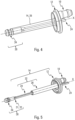
- FIGS. 4 and 5 illustrate in more detail the cylindrical rod 14 of the telescopic cleaning device according to the invention which extends, along the elongation axis X, projecting from the inlet flange 12 and which comprises the heating device 22 consisting of the heating element 24 and the heat-conducting tube 26.
- the heat conducting tube surrounds the heating element 24 and they extend along the elongation axis X in a position centered relative to the inlet flange 12.
- the heating element 24 extends inside the heat conducting tube 26 from the inlet flange 12 to the tip 30 disposed at the end of the heat conducting tube 26.
- the resistive wire forming the heating element 24 has at the tip 30, and therefore in the vicinity of the downstream end of the cylindrical rod, a loop shape so as to have two strands extending side by side, respectively crossing the inlet flange at the passage orifice 28 (visible in the figure 3 , on which only one of the strands of the heating element is visible due to the cut).
- the dimension of the passage orifice 28 is greater than the dimension of the strands of the heating element 24 pressed against each other.
- the heating element has a U shape with the base arranged at the tip 30.
- the tip 30 is here provided with a base 31 intended to be inserted, for example by force, into the heat-conducting tube 26, at the downstream end thereof, and this base comprises an eyelet configured to be crossed by the heating element at its loop. It is understood that during assembly, the end of the heating element is passed into the eyelet forming a holding orifice 32, and the heating element is folded around this eyelet to form the loop.
- a filling material, of the resin or gel type, is injected inside the heat-conducting tube, through the passage orifice 28, once the heating element 24 is in place inside the tube 26.
- This filling material extends in the tube from the base of the end piece 30 to the inlet flange, overflowing if necessary from the passage orifice 28 to spread over the external face of the inlet flange.
- the seal is ensured between the inlet flange 12, the passage orifice 28 through which the heating element 24 enters and exits, and on the other hand, the position of the heating element inside the heat-conducting tube is fixed in order to prevent them from moving during operation.
- the heat-conducting tube 26 is overmolded onto the inlet flange 12, also made of plastic. During this overmolding, the heat-conducting tube is arranged projecting from the inlet flange around the passage orifice 28.
- a resistive wire forming here the heating element 24 is then inserted into the inlet flange 12 via the passage orifice 28 and then pulled, following a first forward trajectory, along the elongation axis X inside the heat-conducting tube 26.
- the end of the heating element protrudes from the downstream end of the heat-conducting tube 26
- the end of the heating element is passed through the holding orifice 32 of the end piece 30 to form a loop and be housed again in the heat-conducting tube 26.
- the heating element is then slid along the tube, following a second return trajectory parallel to the first, until it again passes through the inlet flange 12 at the passage orifice 28.
- the arrangement of the assembly at this stage of the assembly method is illustrated in FIG. figure 4 .
- the tip 30 is then made integral with the heat-conducting tube 26 by crimping or screwing or fitting, and the heating element is stretched at the opposite end at its connection, not shown here, as illustrated in the figure 5 .
- the heating element 24, electrically connected to a power supply via a connector (not visible), is capable of heating the heat-conducting tube 26 composed of a heat-conducting material, preferably brass or aluminum.
- cleaning liquid passes through the hollow conveying body 5 between the rod 14 and the movable piston 8, as may have been specified previously, it may be activated automatically, on request of the user, or following the detection of specific weather conditions, an operation of heating the cleaning liquid by means of the heating device integrated in the rod 14.
- the cylindrical rod 14, equipped with the heating device 22, thus has the function, in addition to its function of guiding the movable piston and its function of controlling the quantity of cleaning liquid passing towards the distribution element, of heating, by conduction, the fluid which enters the cleaning device 3 via an inlet nozzle 10 of the inlet flange 12 and which flows along the outer wall of the cylindrical rod 14.
- the heat-conducting tube 26 has the function of uniformly distributing the heat to be transmitted to the passage of the fluid, and it makes it possible to maintain the heating element 24 in position, if necessary with the aid of the end piece 30 and the filling material.
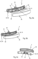
- FIGS. 6a, 6b and 6c illustrate the distribution element 4 of the cleaning device 3 according to the invention consisting, according to a preferred embodiment of the invention, of a distribution ramp 4 comprising an integrated additional heating device 60.
- the distribution ramp 4 extends substantially symmetrically on either side of the elongation axis X of the hollow conveying body 5. More precisely, the distribution ramp 4 comprises, opposite its end portion 45 by which it is attached to the hollow conveying body 5, a distribution portion 62 which extends substantially symmetrically, in a transverse direction Y substantially perpendicular to the elongation axis X, on either side of the downstream end of the conveying body 5 and said elongation axis X.
- the distribution portion 62 is formed of a base 64 forming a first part extending the distribution ramp 4 and capable of being assembled, preferably by welding, to a second part forming a cover 66 so as to define between these two parts the fluid distribution channel 56 comprising in the lower part a plurality of fluid distribution orifices 68 for ejecting the latter towards the optical surface. to be cleaned when the distribution element 4 is in the deployed position.
- the distribution ramp 4 is specific here in that it includes an additional heating device 60 integrated into the ramp and independent of the heating device 22 present in the rod 14 as described previously.
- the additional heating device 60 here comprises an additional heating wire 70, separate from the heating element 24 housed in the tube 26 of the rod 14, and electrically connected to an electrical power supply via a connector not shown here.
- the additional heating wire 70 comprises a part internal to the distribution ramp 4, and a part external to the ramp capable of being connected to the connector.
- a passage orifice 72, made in the base 64, makes it possible to connect these two parts of the additional heating wire, allowing the passage of the additional heating wire 70 through the base.
- the diameter of the passage orifice 64 is greater than the external diameter of the additional heating wire.
- the internal part of the ramp of the additional heating wire 70 runs along the fluid distribution channel 56, being held on the internal face of the base 64 of the distribution portion 62, that is to say the face of the base facing the cover 66, by means of a plurality of holding studs 74 arranged on this internal face of the base.
- the length of the inner portion of the additional heating wire 70 is defined as a function of the length of the fluid distribution channel 56, and the length of the outer portion of the additional heating wire is defined so as to allow the movement of the movable piston 8 of the telescopic cleaning device 3 in its extreme deployed position. Provision may be made to arrange the outer portion of the additional heating wire in a sheath so that it does not become tangled when the distribution element passes into the retracted position.
- a filling material, of the resin or gel type can be added in the passage orifice 72 to ensure the seal between the distribution portion 62, the passage orifice 72 and the additional heating wire 70.
- the cleaning device comprises at least one heating device arranged in the hollow conveying body and more particularly in the rod around which the movable piston slides for the telescopic deployment of the distribution element carried at the end of this hollow body. routing. It will be possible to additionally provide a first additional heating device as just described at the level of the distribution element, and it will be possible, alternatively or cumulatively to this first additional heating device, to provide for a second additional heating device in a cleaning and/or drying fluid routing conduit arranged upstream of the heated cleaning device 3 according to the invention for its fluid supply, the second additional heating device taking the form of a resistive wire connected to a connector and arranged in or around the perimeter of the routing conduit.
Landscapes
- Engineering & Computer Science (AREA)
- Mechanical Engineering (AREA)
- Water Supply & Treatment (AREA)
- Physics & Mathematics (AREA)
- Computer Networks & Wireless Communication (AREA)
- Electromagnetism (AREA)
- General Physics & Mathematics (AREA)
- Radar, Positioning & Navigation (AREA)
- Remote Sensing (AREA)
- Nozzles (AREA)
Claims (12)
- Teleskopische Reinigungsvorrichtung (3), welche dazu bestimmt ist, mindestens ein Reinigungs- und/oder Trocknungsfluid auf eine zu reinigende Glasfläche eines Kraftfahrzeugs (1), wie etwa eine optische Fläche (2') eines optischen Sensors (2) eines optischen Detektionssystems, zu sprühen, und mindestens einen Führungshohlkörper (5) für Reinigungsfluid umfasst, der an einem stromaufwärtigen Ende durch einen Eintrittsflansch (12) verschlossen ist und einen beweglichen Kolben (8) aufnimmt, der dafür ausgelegt ist, in dem Führungshohlkörper (5) parallel zu einer Längsachse (X) des Hohlkörpers zu gleiten, wobei der bewegliche Kolben (8), der von einem inneren Verteilungskanal (50) durchquert wird, an einem stromabwärtigen Ende ein Fluidverteilungselement (4) trägt,wobei der Führungshohlkörper (5) außerdem eine Stange (14) aufnimmt, die sich aus dem Eintrittsflansch (12) vorstehend entlang der Längsachse (X) erstreckt und um die herum der bewegliche Kolben gleiten kann, wobei der bewegliche Kolben (8) und die Stange (14) dafür ausgelegt sind, zwischen sich, in Abhängigkeit von der Position des beweglichen Kolbens (8) bezüglich der Stange (14), das Fließen des Fluids vom Eintrittsflansch (12) bis zum Verteilungselement (4) zu ermöglichen,und wobei die Stange (14) eine Heizvorrichtung (22) aufweist, wobei die Heizvorrichtung (22) mindestens ein Heizelement (24) aufweist, das sich im Inneren eines wärmeleitenden Rohres (26) entlang der Längsachse (X) erstreckt.
- Teleskopische Reinigungsvorrichtung (3) nach Anspruch 1, dadurch gekennzeichnet, dass das wärmeleitende Rohr (26) eine äußere Hülle der Stange (14) definiert, wobei bewirkt wird, dass das zwischen der Stange (14) und dem beweglichen Kolben (8) strömende Fluid die Außenwand des wärmeleitenden Rohres anströmt.
- Teleskopische Reinigungsvorrichtung (3) nach Anspruch 1 oder 2, dadurch gekennzeichnet, dass sich das Heizelement (24) im Inneren der Stange vom Eintrittsflansch (12) aus und/oder bis zum dem Eintrittsflansch (12) gegenüberliegenden freien Ende der Stange (14) erstreckt.
- Teleskopische Reinigungsvorrichtung (3) nach einem der vorhergehenden Ansprüche, dadurch gekennzeichnet, dass das Heizelement (24) ein Widerstandsdraht ist.
- Teleskopische Reinigungsvorrichtung (3) nach dem vorhergehenden Anspruch, dadurch gekennzeichnet, dass das Heizelement (24) ein Widerstandsdraht ist, der eine Schleife im Inneren des wärmeleitenden Rohres (26) bildet.
- Teleskopische Reinigungsvorrichtung (3) nach einem der vorhergehenden Ansprüche, dadurch gekennzeichnet, dass die Stange (14) ein im Wesentlichen zylindrisches Endstück (30) aufweist, welches Haltemittel (32) für das Heizelement (24) aufweist.
- Teleskopische Reinigungsvorrichtung (3) nach dem vorhergehenden Anspruch, dadurch gekennzeichnet, dass das Endstück (30) durch Quetschverbindung oder Verschraubung oder Aufstecken fest mit einem stromabwärtigen Ende des wärmeleitenden Rohres (26) verbunden ist.
- Teleskopische Reinigungsvorrichtung (3) nach einem der vorhergehenden Ansprüche, dadurch gekennzeichnet, dass ein Füllmaterial, insbesondere von der Art eines Harzes oder Gels, wenigstens teilweise im Inneren des leitenden Rohres (26) angeordnet ist, um die Position des Heizelements (24) zu fixieren.
- Teleskopische Reinigungsvorrichtung (3) nach einem der vorhergehenden Ansprüche, dadurch gekennzeichnet, dass das wärmeleitende Rohr (26) metallisch ist, insbesondere aus Messing oder Aluminium besteht.
- Teleskopische Reinigungsvorrichtung (3) nach einem der vorhergehenden Ansprüche in Verbindung mit Anspruch 6, dadurch gekennzeichnet, dass das Endstück (30) aus Kunststoff besteht.
- Teleskopische Reinigungsvorrichtung (3) nach einem der vorhergehenden Ansprüche, dadurch gekennzeichnet, dass das Fluidverteilungselement (4) ein Verteilergestell aufweist, das mit einer zusätzlichen Heizvorrichtung (60) ausgestattet ist, welche einen zusätzlichen Heizdraht (70) aufweist, der von dem in der Stange (14) aufgenommenen Heizelement (24) verschieden ist.
- Optisches Detektionssystem, welches zur Ausrüstung eines Kraftfahrzeugs bestimmt ist, wobei das System mindestens einen mit einer optischen Fläche (2') ausgestatteten optischen Sensor (2) aufweist, dadurch gekennzeichnet, dass es eine teleskopische Reinigungsvorrichtung (3) für die optische Fläche (2') nach einem der Ansprüche 1 bis 11 aufweist.
Applications Claiming Priority (1)
| Application Number | Priority Date | Filing Date | Title |
|---|---|---|---|
| FR1753576A FR3065381B1 (fr) | 2017-04-25 | 2017-04-25 | Dispositif de nettoyage telescopique |
Publications (2)
| Publication Number | Publication Date |
|---|---|
| EP3395626A1 EP3395626A1 (de) | 2018-10-31 |
| EP3395626B1 true EP3395626B1 (de) | 2024-12-04 |
Family
ID=58993138
Family Applications (1)
| Application Number | Title | Priority Date | Filing Date |
|---|---|---|---|
| EP18167190.0A Active EP3395626B1 (de) | 2017-04-25 | 2018-04-13 | Teleskopreinigungsvorrichtung |
Country Status (7)
| Country | Link |
|---|---|
| US (1) | US10919501B2 (de) |
| EP (1) | EP3395626B1 (de) |
| JP (1) | JP7036657B2 (de) |
| KR (1) | KR20180119524A (de) |
| CN (1) | CN108725389B (de) |
| CA (1) | CA3002363A1 (de) |
| FR (1) | FR3065381B1 (de) |
Families Citing this family (9)
| Publication number | Priority date | Publication date | Assignee | Title |
|---|---|---|---|---|
| FR3056518B1 (fr) * | 2016-09-28 | 2018-10-26 | Valeo Systemes D'essuyage | Dispositif de nettoyage d'un capteur optique d'un systeme de detection optique pour vehicule automobile |
| WO2020153115A1 (ja) * | 2019-01-25 | 2020-07-30 | トヨタ自動車株式会社 | 車両用クリーナ |
| CN109969140A (zh) * | 2019-04-30 | 2019-07-05 | 奇瑞汽车股份有限公司 | 清洗装置及清洗方法 |
| FR3099448B1 (fr) * | 2019-07-31 | 2021-07-16 | Valeo Systemes Dessuyage | Organe de distribution et de projection destiné à un système de nettoyage pour un bloc de capteurs de véhicule automobile |
| US20220390568A1 (en) * | 2019-10-23 | 2022-12-08 | Koito Manufacturing Co., Ltd. | Sensor system and sensor unit |
| KR102777787B1 (ko) * | 2020-06-03 | 2025-03-06 | 현대자동차주식회사 | 워셔액 분배장치 |
| DE102021102620A1 (de) | 2021-02-04 | 2022-08-04 | Valeo Systèmes d'Éssuyage SAS | Reinigungseinrichtung für eine Umfelderkennungseinrichtung eines Fahrzeugs und Umfelderkennungseinrichtung |
| KR20240096157A (ko) * | 2022-12-19 | 2024-06-26 | 현대자동차주식회사 | 센서부 세척 장치 |
| KR20240165712A (ko) * | 2023-05-16 | 2024-11-25 | 현대자동차주식회사 | 노즐 시스템 |
Family Cites Families (13)
| Publication number | Priority date | Publication date | Assignee | Title |
|---|---|---|---|---|
| GB213445A (en) * | 1923-04-19 | 1924-04-03 | Swann Hunter & Wigham Richards | Improvements in or relating to pistons for internal combustion engines |
| JPH02109761A (ja) * | 1988-10-19 | 1990-04-23 | Kazuo Sawara | 自動車のウインドウォッシャ液加熱装置 |
| JPH05326118A (ja) * | 1992-05-19 | 1993-12-10 | Kawai Denki Seisakusho:Kk | 棒状ヒータ、その製造用治具及び棒状ヒータの製造方法 |
| DE4237856C1 (de) * | 1992-11-10 | 1993-10-14 | Daimler Benz Ag | Scheinwerferwaschvorrichtung |
| US6896199B2 (en) * | 2002-05-31 | 2005-05-24 | Valeo Electrical Systems, Inc. | Washing apparatus for multiple vehicle surfaces |
| WO2009138105A1 (en) * | 2008-05-14 | 2009-11-19 | Kautex Textron Gmbh & Co. Kg | Light cleaning device |
| CN201276095Y (zh) * | 2008-09-25 | 2009-07-22 | 科博达技术有限公司 | 伸缩式汽车前照灯清洗器 |
| DE102009006280A1 (de) * | 2009-01-27 | 2010-07-29 | Daimler Ag | Scheinwerferreinigungsanlage |
| KR101063398B1 (ko) * | 2009-12-01 | 2011-09-07 | 기아자동차주식회사 | 와셔액 가열기능을 갖는 와셔펌프장치 |
| FR3021014B1 (fr) * | 2014-05-14 | 2016-05-27 | Coutier Moulage Gen Ind | Dispositif telescopique de lavage |
| US20160167624A1 (en) * | 2014-12-16 | 2016-06-16 | Jere Rask Lansinger | Electrically heating windshield washer fluid system |
| FR3039113B1 (fr) * | 2015-07-22 | 2017-07-28 | Valeo Systemes Dessuyage | Dispositif de nettoyage d'un capteur pour vehicule automobile |
| JP6817691B2 (ja) * | 2015-08-11 | 2021-01-20 | 株式会社村上開明堂 | ウォッシャー液の加熱装置 |
-
2017
- 2017-04-25 FR FR1753576A patent/FR3065381B1/fr not_active Expired - Fee Related
-
2018
- 2018-04-13 EP EP18167190.0A patent/EP3395626B1/de active Active
- 2018-04-20 CA CA3002363A patent/CA3002363A1/en not_active Abandoned
- 2018-04-24 US US15/960,935 patent/US10919501B2/en active Active
- 2018-04-24 JP JP2018083125A patent/JP7036657B2/ja active Active
- 2018-04-25 CN CN201810378202.8A patent/CN108725389B/zh active Active
- 2018-04-25 KR KR1020180048061A patent/KR20180119524A/ko not_active Withdrawn
Also Published As
| Publication number | Publication date |
|---|---|
| JP7036657B2 (ja) | 2022-03-15 |
| EP3395626A1 (de) | 2018-10-31 |
| JP2018199483A (ja) | 2018-12-20 |
| US10919501B2 (en) | 2021-02-16 |
| CN108725389A (zh) | 2018-11-02 |
| FR3065381A1 (fr) | 2018-10-26 |
| US20180304862A1 (en) | 2018-10-25 |
| KR20180119524A (ko) | 2018-11-02 |
| CN108725389B (zh) | 2021-09-21 |
| FR3065381B1 (fr) | 2020-10-30 |
| CA3002363A1 (en) | 2018-10-25 |
Similar Documents
| Publication | Publication Date | Title |
|---|---|---|
| EP3395626B1 (de) | Teleskopreinigungsvorrichtung | |
| EP3395624B1 (de) | Teleskopreinigungsvorrichtung | |
| EP3006279B1 (de) | Reinigungsvorrichtung für eine kamera eines fahrerassistenzsystems in einem kraftfahrzeug | |
| EP3519260B1 (de) | Reinigungsvorrichtung zum aufsprühen mindestens einer flüssigkeit auf eine zu reinigende oberfläche eines kraftfahrzeugs | |
| EP3519259B1 (de) | Reinigungsvorrichtung zum versprühen von mindestens einer flüssigkeit auf eine zu reinigende oberfläche eines kraftfahrzeugs | |
| EP2794367B1 (de) | Wärmeleitendes kunststoffbauteil für ein system zur zufuhr von und/oder verteilung einer scheibenwaschflüssigkeit für ein kraftfahrzeug | |
| EP3519263B1 (de) | Vorrichtung zur reinigung eines optischen sensors eines optischen detektionssystems für ein kraftfahrzeug | |
| EP3902723B1 (de) | Flüssigkeitssprühdüse für eine reinigungsvorrichtung eines optischen detektionssystems | |
| EP3121071A1 (de) | Reinigungsvorrichtung eines sensors für kraftfahrzeug | |
| EP3300971B1 (de) | Reinigungsvorrichtung zum spritzen mindestens einer flüssigkeit auf eine zu reinigende oberfläche eines kraftfahrzeugs | |
| WO2017174918A1 (fr) | Ensemble de distribution de produit fluide | |
| EP3395625B1 (de) | Teleskopreinigungsvorrichtung | |
| FR3056515B1 (fr) | Dispositif de nettoyage d'une surface exterieure d'un capteur d'un vehicule automobile | |
| EP3250422A1 (de) | Flüssigkeitsverteilungsventil für ein flüssigkeitsverteilungssystem eines fahrzeugwäschers | |
| FR3013288A1 (fr) | Balai d'essuie-glace d'une vitre d'un vehicule | |
| WO2022043000A1 (fr) | Dispositif de projection de fluide pour le nettoyage d'une surface d'un véhicule automobile. | |
| FR2969734A1 (fr) | Dispositif de commande du debit d’un fluide de refroidissement | |
| FR3098775A1 (fr) | Dispositif d’essuie-glace | |
| FR2904064A1 (fr) | Element thermostatique,vanne de regulation comportant un tel element et circuit de liquide de refroidissement incorporant une telle vanne | |
| FR3113269A1 (fr) | Dispositif de nettoyage pour nettoyer sélectivement un équipement automobile | |
| WO2024061850A1 (fr) | Buse de projection d'un dispositif de projection |
Legal Events
| Date | Code | Title | Description |
|---|---|---|---|
| PUAI | Public reference made under article 153(3) epc to a published international application that has entered the european phase |
Free format text: ORIGINAL CODE: 0009012 |
|
| STAA | Information on the status of an ep patent application or granted ep patent |
Free format text: STATUS: REQUEST FOR EXAMINATION WAS MADE |
|
| 17P | Request for examination filed |
Effective date: 20180413 |
|
| AK | Designated contracting states |
Kind code of ref document: A1 Designated state(s): AL AT BE BG CH CY CZ DE DK EE ES FI FR GB GR HR HU IE IS IT LI LT LU LV MC MK MT NL NO PL PT RO RS SE SI SK SM TR |
|
| AX | Request for extension of the european patent |
Extension state: BA ME |
|
| STAA | Information on the status of an ep patent application or granted ep patent |
Free format text: STATUS: EXAMINATION IS IN PROGRESS |
|
| 17Q | First examination report despatched |
Effective date: 20220126 |
|
| P01 | Opt-out of the competence of the unified patent court (upc) registered |
Effective date: 20230528 |
|
| GRAP | Despatch of communication of intention to grant a patent |
Free format text: ORIGINAL CODE: EPIDOSNIGR1 |
|
| STAA | Information on the status of an ep patent application or granted ep patent |
Free format text: STATUS: GRANT OF PATENT IS INTENDED |
|
| RIC1 | Information provided on ipc code assigned before grant |
Ipc: B08B 3/02 20060101ALN20240207BHEP Ipc: B60S 1/52 20060101ALI20240207BHEP Ipc: B60S 1/08 20060101AFI20240207BHEP |
|
| INTG | Intention to grant announced |
Effective date: 20240223 |
|
| GRAJ | Information related to disapproval of communication of intention to grant by the applicant or resumption of examination proceedings by the epo deleted |
Free format text: ORIGINAL CODE: EPIDOSDIGR1 |
|
| STAA | Information on the status of an ep patent application or granted ep patent |
Free format text: STATUS: EXAMINATION IS IN PROGRESS |
|
| GRAP | Despatch of communication of intention to grant a patent |
Free format text: ORIGINAL CODE: EPIDOSNIGR1 |
|
| STAA | Information on the status of an ep patent application or granted ep patent |
Free format text: STATUS: GRANT OF PATENT IS INTENDED |
|
| INTC | Intention to grant announced (deleted) | ||
| RIC1 | Information provided on ipc code assigned before grant |
Ipc: B08B 3/02 20060101ALN20240704BHEP Ipc: B60S 1/52 20060101ALI20240704BHEP Ipc: B60S 1/08 20060101AFI20240704BHEP |
|
| INTG | Intention to grant announced |
Effective date: 20240712 |
|
| GRAS | Grant fee paid |
Free format text: ORIGINAL CODE: EPIDOSNIGR3 |
|
| GRAA | (expected) grant |
Free format text: ORIGINAL CODE: 0009210 |
|
| STAA | Information on the status of an ep patent application or granted ep patent |
Free format text: STATUS: THE PATENT HAS BEEN GRANTED |
|
| AK | Designated contracting states |
Kind code of ref document: B1 Designated state(s): AL AT BE BG CH CY CZ DE DK EE ES FI FR GB GR HR HU IE IS IT LI LT LU LV MC MK MT NL NO PL PT RO RS SE SI SK SM TR |
|
| REG | Reference to a national code |
Ref country code: GB Ref legal event code: FG4D Free format text: NOT ENGLISH |
|
| REG | Reference to a national code |
Ref country code: CH Ref legal event code: EP |
|
| REG | Reference to a national code |
Ref country code: DE Ref legal event code: R096 Ref document number: 602018077168 Country of ref document: DE |
|
| REG | Reference to a national code |
Ref country code: IE Ref legal event code: FG4D Free format text: LANGUAGE OF EP DOCUMENT: FRENCH |
|
| REG | Reference to a national code |
Ref country code: LT Ref legal event code: MG9D |
|
| REG | Reference to a national code |
Ref country code: NL Ref legal event code: MP Effective date: 20241204 |
|
| PG25 | Lapsed in a contracting state [announced via postgrant information from national office to epo] |
Ref country code: HR Free format text: LAPSE BECAUSE OF FAILURE TO SUBMIT A TRANSLATION OF THE DESCRIPTION OR TO PAY THE FEE WITHIN THE PRESCRIBED TIME-LIMIT Effective date: 20241204 |
|
| PG25 | Lapsed in a contracting state [announced via postgrant information from national office to epo] |
Ref country code: FI Free format text: LAPSE BECAUSE OF FAILURE TO SUBMIT A TRANSLATION OF THE DESCRIPTION OR TO PAY THE FEE WITHIN THE PRESCRIBED TIME-LIMIT Effective date: 20241204 |
|
| PG25 | Lapsed in a contracting state [announced via postgrant information from national office to epo] |
Ref country code: BG Free format text: LAPSE BECAUSE OF FAILURE TO SUBMIT A TRANSLATION OF THE DESCRIPTION OR TO PAY THE FEE WITHIN THE PRESCRIBED TIME-LIMIT Effective date: 20241204 |
|
| PG25 | Lapsed in a contracting state [announced via postgrant information from national office to epo] |
Ref country code: ES Free format text: LAPSE BECAUSE OF FAILURE TO SUBMIT A TRANSLATION OF THE DESCRIPTION OR TO PAY THE FEE WITHIN THE PRESCRIBED TIME-LIMIT Effective date: 20241204 |
|
| PG25 | Lapsed in a contracting state [announced via postgrant information from national office to epo] |
Ref country code: NO Free format text: LAPSE BECAUSE OF FAILURE TO SUBMIT A TRANSLATION OF THE DESCRIPTION OR TO PAY THE FEE WITHIN THE PRESCRIBED TIME-LIMIT Effective date: 20250304 |
|
| PG25 | Lapsed in a contracting state [announced via postgrant information from national office to epo] |
Ref country code: GR Free format text: LAPSE BECAUSE OF FAILURE TO SUBMIT A TRANSLATION OF THE DESCRIPTION OR TO PAY THE FEE WITHIN THE PRESCRIBED TIME-LIMIT Effective date: 20250305 Ref country code: LV Free format text: LAPSE BECAUSE OF FAILURE TO SUBMIT A TRANSLATION OF THE DESCRIPTION OR TO PAY THE FEE WITHIN THE PRESCRIBED TIME-LIMIT Effective date: 20241204 |
|
| PG25 | Lapsed in a contracting state [announced via postgrant information from national office to epo] |
Ref country code: RS Free format text: LAPSE BECAUSE OF FAILURE TO SUBMIT A TRANSLATION OF THE DESCRIPTION OR TO PAY THE FEE WITHIN THE PRESCRIBED TIME-LIMIT Effective date: 20250304 |
|
| PG25 | Lapsed in a contracting state [announced via postgrant information from national office to epo] |
Ref country code: NL Free format text: LAPSE BECAUSE OF FAILURE TO SUBMIT A TRANSLATION OF THE DESCRIPTION OR TO PAY THE FEE WITHIN THE PRESCRIBED TIME-LIMIT Effective date: 20241204 |
|
| REG | Reference to a national code |
Ref country code: AT Ref legal event code: MK05 Ref document number: 1747867 Country of ref document: AT Kind code of ref document: T Effective date: 20241204 |
|
| PG25 | Lapsed in a contracting state [announced via postgrant information from national office to epo] |
Ref country code: SM Free format text: LAPSE BECAUSE OF FAILURE TO SUBMIT A TRANSLATION OF THE DESCRIPTION OR TO PAY THE FEE WITHIN THE PRESCRIBED TIME-LIMIT Effective date: 20241204 |
|
| PG25 | Lapsed in a contracting state [announced via postgrant information from national office to epo] |
Ref country code: PL Free format text: LAPSE BECAUSE OF FAILURE TO SUBMIT A TRANSLATION OF THE DESCRIPTION OR TO PAY THE FEE WITHIN THE PRESCRIBED TIME-LIMIT Effective date: 20241204 |
|
| PGFP | Annual fee paid to national office [announced via postgrant information from national office to epo] |
Ref country code: DE Payment date: 20250411 Year of fee payment: 8 |
|
| PG25 | Lapsed in a contracting state [announced via postgrant information from national office to epo] |
Ref country code: IS Free format text: LAPSE BECAUSE OF FAILURE TO SUBMIT A TRANSLATION OF THE DESCRIPTION OR TO PAY THE FEE WITHIN THE PRESCRIBED TIME-LIMIT Effective date: 20250404 |
|
| PG25 | Lapsed in a contracting state [announced via postgrant information from national office to epo] |
Ref country code: PT Free format text: LAPSE BECAUSE OF FAILURE TO SUBMIT A TRANSLATION OF THE DESCRIPTION OR TO PAY THE FEE WITHIN THE PRESCRIBED TIME-LIMIT Effective date: 20250404 |
|
| PG25 | Lapsed in a contracting state [announced via postgrant information from national office to epo] |
Ref country code: EE Free format text: LAPSE BECAUSE OF FAILURE TO SUBMIT A TRANSLATION OF THE DESCRIPTION OR TO PAY THE FEE WITHIN THE PRESCRIBED TIME-LIMIT Effective date: 20241204 |
|
| PGFP | Annual fee paid to national office [announced via postgrant information from national office to epo] |
Ref country code: FR Payment date: 20250429 Year of fee payment: 8 |
|
| PG25 | Lapsed in a contracting state [announced via postgrant information from national office to epo] |
Ref country code: AT Free format text: LAPSE BECAUSE OF FAILURE TO SUBMIT A TRANSLATION OF THE DESCRIPTION OR TO PAY THE FEE WITHIN THE PRESCRIBED TIME-LIMIT Effective date: 20241204 Ref country code: RO Free format text: LAPSE BECAUSE OF FAILURE TO SUBMIT A TRANSLATION OF THE DESCRIPTION OR TO PAY THE FEE WITHIN THE PRESCRIBED TIME-LIMIT Effective date: 20241204 |
|
| PG25 | Lapsed in a contracting state [announced via postgrant information from national office to epo] |
Ref country code: SK Free format text: LAPSE BECAUSE OF FAILURE TO SUBMIT A TRANSLATION OF THE DESCRIPTION OR TO PAY THE FEE WITHIN THE PRESCRIBED TIME-LIMIT Effective date: 20241204 |
|
| PG25 | Lapsed in a contracting state [announced via postgrant information from national office to epo] |
Ref country code: CZ Free format text: LAPSE BECAUSE OF FAILURE TO SUBMIT A TRANSLATION OF THE DESCRIPTION OR TO PAY THE FEE WITHIN THE PRESCRIBED TIME-LIMIT Effective date: 20241204 |
|
| PG25 | Lapsed in a contracting state [announced via postgrant information from national office to epo] |
Ref country code: IT Free format text: LAPSE BECAUSE OF FAILURE TO SUBMIT A TRANSLATION OF THE DESCRIPTION OR TO PAY THE FEE WITHIN THE PRESCRIBED TIME-LIMIT Effective date: 20241204 |
|
| REG | Reference to a national code |
Ref country code: DE Ref legal event code: R097 Ref document number: 602018077168 Country of ref document: DE |
|
| PG25 | Lapsed in a contracting state [announced via postgrant information from national office to epo] |
Ref country code: SE Free format text: LAPSE BECAUSE OF FAILURE TO SUBMIT A TRANSLATION OF THE DESCRIPTION OR TO PAY THE FEE WITHIN THE PRESCRIBED TIME-LIMIT Effective date: 20241204 |
|
| PG25 | Lapsed in a contracting state [announced via postgrant information from national office to epo] |
Ref country code: DK Free format text: LAPSE BECAUSE OF FAILURE TO SUBMIT A TRANSLATION OF THE DESCRIPTION OR TO PAY THE FEE WITHIN THE PRESCRIBED TIME-LIMIT Effective date: 20241204 |
|
| PLBE | No opposition filed within time limit |
Free format text: ORIGINAL CODE: 0009261 |
|
| STAA | Information on the status of an ep patent application or granted ep patent |
Free format text: STATUS: NO OPPOSITION FILED WITHIN TIME LIMIT |
|
| REG | Reference to a national code |
Ref country code: CH Ref legal event code: L10 Free format text: ST27 STATUS EVENT CODE: U-0-0-L10-L00 (AS PROVIDED BY THE NATIONAL OFFICE) Effective date: 20251015 |
|
| 26N | No opposition filed |
Effective date: 20250905 |
|
| REG | Reference to a national code |
Ref country code: CH Ref legal event code: H13 Free format text: ST27 STATUS EVENT CODE: U-0-0-H10-H13 (AS PROVIDED BY THE NATIONAL OFFICE) Effective date: 20251125 |
|
| PG25 | Lapsed in a contracting state [announced via postgrant information from national office to epo] |
Ref country code: LU Free format text: LAPSE BECAUSE OF NON-PAYMENT OF DUE FEES Effective date: 20250413 |
|
| PG25 | Lapsed in a contracting state [announced via postgrant information from national office to epo] |
Ref country code: MC Free format text: LAPSE BECAUSE OF FAILURE TO SUBMIT A TRANSLATION OF THE DESCRIPTION OR TO PAY THE FEE WITHIN THE PRESCRIBED TIME-LIMIT Effective date: 20241204 |
|
| GBPC | Gb: european patent ceased through non-payment of renewal fee |
Effective date: 20250413 |
|
| REG | Reference to a national code |
Ref country code: BE Ref legal event code: MM Effective date: 20250430 |
|
| PG25 | Lapsed in a contracting state [announced via postgrant information from national office to epo] |
Ref country code: GB Free format text: LAPSE BECAUSE OF NON-PAYMENT OF DUE FEES Effective date: 20250413 |
|
| PG25 | Lapsed in a contracting state [announced via postgrant information from national office to epo] |
Ref country code: BE Free format text: LAPSE BECAUSE OF NON-PAYMENT OF DUE FEES Effective date: 20250430 |
|
| PG25 | Lapsed in a contracting state [announced via postgrant information from national office to epo] |
Ref country code: CH Free format text: LAPSE BECAUSE OF NON-PAYMENT OF DUE FEES Effective date: 20250430 |
|
| PG25 | Lapsed in a contracting state [announced via postgrant information from national office to epo] |
Ref country code: IE Free format text: LAPSE BECAUSE OF NON-PAYMENT OF DUE FEES Effective date: 20250413 |