EP3396014A1 - Dispositif de dépôt sous vide pour revêtement à grande vitesse - Google Patents
Dispositif de dépôt sous vide pour revêtement à grande vitesse Download PDFInfo
- Publication number
- EP3396014A1 EP3396014A1 EP16879251.3A EP16879251A EP3396014A1 EP 3396014 A1 EP3396014 A1 EP 3396014A1 EP 16879251 A EP16879251 A EP 16879251A EP 3396014 A1 EP3396014 A1 EP 3396014A1
- Authority
- EP
- European Patent Office
- Prior art keywords
- cyclone filter
- steam
- coating
- range
- coating material
- Prior art date
- Legal status (The legal status is an assumption and is not a legal conclusion. Google has not performed a legal analysis and makes no representation as to the accuracy of the status listed.)
- Withdrawn
Links
Images


Classifications
-
- B—PERFORMING OPERATIONS; TRANSPORTING
- B04—CENTRIFUGAL APPARATUS OR MACHINES FOR CARRYING-OUT PHYSICAL OR CHEMICAL PROCESSES
- B04C—APPARATUS USING FREE VORTEX FLOW, e.g. CYCLONES
- B04C5/00—Apparatus in which the axial direction of the vortex is reversed
- B04C5/08—Vortex chamber constructions
- B04C5/103—Bodies or members, e.g. bulkheads, guides, in the vortex chamber
-
- C—CHEMISTRY; METALLURGY
- C23—COATING METALLIC MATERIAL; COATING MATERIAL WITH METALLIC MATERIAL; CHEMICAL SURFACE TREATMENT; DIFFUSION TREATMENT OF METALLIC MATERIAL; COATING BY VACUUM EVAPORATION, BY SPUTTERING, BY ION IMPLANTATION OR BY CHEMICAL VAPOUR DEPOSITION, IN GENERAL; INHIBITING CORROSION OF METALLIC MATERIAL OR INCRUSTATION IN GENERAL
- C23C—COATING METALLIC MATERIAL; COATING MATERIAL WITH METALLIC MATERIAL; SURFACE TREATMENT OF METALLIC MATERIAL BY DIFFUSION INTO THE SURFACE, BY CHEMICAL CONVERSION OR SUBSTITUTION; COATING BY VACUUM EVAPORATION, BY SPUTTERING, BY ION IMPLANTATION OR BY CHEMICAL VAPOUR DEPOSITION, IN GENERAL
- C23C14/00—Coating by vacuum evaporation, by sputtering or by ion implantation of the coating forming material
- C23C14/22—Coating by vacuum evaporation, by sputtering or by ion implantation of the coating forming material characterised by the process of coating
- C23C14/24—Vacuum evaporation
- C23C14/243—Crucibles for source material
-
- B—PERFORMING OPERATIONS; TRANSPORTING
- B01—PHYSICAL OR CHEMICAL PROCESSES OR APPARATUS IN GENERAL
- B01D—SEPARATION
- B01D45/00—Separating dispersed particles from gases or vapours by gravity, inertia, or centrifugal forces
- B01D45/12—Separating dispersed particles from gases or vapours by gravity, inertia, or centrifugal forces by centrifugal forces
- B01D45/16—Separating dispersed particles from gases or vapours by gravity, inertia, or centrifugal forces by centrifugal forces generated by the winding course of the gas stream, the centrifugal forces being generated solely or partly by mechanical means, e.g. fixed swirl vanes
-
- C—CHEMISTRY; METALLURGY
- C23—COATING METALLIC MATERIAL; COATING MATERIAL WITH METALLIC MATERIAL; CHEMICAL SURFACE TREATMENT; DIFFUSION TREATMENT OF METALLIC MATERIAL; COATING BY VACUUM EVAPORATION, BY SPUTTERING, BY ION IMPLANTATION OR BY CHEMICAL VAPOUR DEPOSITION, IN GENERAL; INHIBITING CORROSION OF METALLIC MATERIAL OR INCRUSTATION IN GENERAL
- C23C—COATING METALLIC MATERIAL; COATING MATERIAL WITH METALLIC MATERIAL; SURFACE TREATMENT OF METALLIC MATERIAL BY DIFFUSION INTO THE SURFACE, BY CHEMICAL CONVERSION OR SUBSTITUTION; COATING BY VACUUM EVAPORATION, BY SPUTTERING, BY ION IMPLANTATION OR BY CHEMICAL VAPOUR DEPOSITION, IN GENERAL
- C23C14/00—Coating by vacuum evaporation, by sputtering or by ion implantation of the coating forming material
- C23C14/22—Coating by vacuum evaporation, by sputtering or by ion implantation of the coating forming material characterised by the process of coating
- C23C14/24—Vacuum evaporation
- C23C14/26—Vacuum evaporation by resistance or inductive heating of the source
Definitions
- the present invention relates to a vacuum deposition device for high-speed coating, and more specifically, to a vacuum deposition device for high-speed coating which removes coarse particles generated during high-speed coating.
- Vacuum deposition is a technology of forming a thin film by heating and evaporating a solid coating material by various methods under a vacuum condition to be changed into steam and spraying the steam to a plating target object, and a coating method is mainly classified according to a heating method.
- Typical vacuum deposition methods include a thermal evaporation method, an electron beam evaporation method, and an electro-magnetic levitation evaporation method.
- the thermal evaporation method is a method of coating a substrate by heating and evaporating a solid coating material, which is put in a filament, a boat, or a crucible made of metal, ceramic, or graphite, by resistive heating. Since the method is limited to heating of a coating material by resistive heating, it is almost impossible to coat a high melting point material such as titanium, chrome or the like. Therefore, the method is widely used for coating a low melting point material such as zinc, magnesium or the like.
- the electron beam evaporation method allows a high melting point material to be evaporated by locally heating a solid coating material, which is put in a water-cooled copper or ceramic crucible, by an electron beam.
- a disadvantage of low energy efficiency due to heat loss caused by a contact between the evaporated material and the crucible.
- the electro-magnetic levitation evaporation method is a technology of generating coating steam by levitating and heating an electrically conductive material in an electro-magnetic coil, especially a metal, by electromagnetic force in a vacuum atmosphere, and continuously spraying the coating steam to a moving substrate through a ceramic tube and a heated steam box.
- the method is used for a strip to be coated with a low melting point metal, such as zinc, magnesium or the like, and has an advantage of high energy efficiency.
- Determining a coating speed in the vacuum deposition method depends on a heating temperature and an evaporation pressure of the coating material.
- the evaporation pressure is an inherent property of matter, it cannot be controlled, and thus a heating temperature of a coating material should increase so that the coating speed increases.
- heating power of the coating material should increase so that high speed coating is performed, but the high speed coating has limitations due to the coarse particles that degrade the quality of coating.
- Technologies for removing coarse particles generated during the vacuum deposition is mainly classified into a technology of preventing boiling of coarse particles, a technology of preventing condensation due to heat radiating expansion at a steam ejection opening, and a technology of inserting a member configured to block coarse particles.
- heaters are mounted not only on an outside of a vacuum deposition crucible but also above a coating material in the crucible to heat the coating material, and a carbon block has a gap with a surface of the coating material to prevent boiling of the coating material due to an increase in temperature of the surface of the coating material, and thus production of coarse particles is prevented.
- the technology can prevent boiling of coarse particles generated during deposition but is inadequate to technology of removing coarse particles at a level applicable to high speed coating.
- heating power of the coating material should increase to perform high speed coating, but it is practically difficult to perform the high speed coating while a temperature of a surface of the coating material is maintained at high temperatures while an interior temperature of the coating material is maintained under a boiling point by the technology of preventing boiling of the coating material.
- the source for depositing an organic EL device including unequally arranged heating units uses a different technical unit but removes coarse particles by preventing steam from being condensed at the steam ejection opening by heating units additionally mounted at the steam ejection opening or concentrically disposed.
- a blocking member In the technology of inserting a member blocking a coarse particle, a blocking member is used to block steam, and thus there is a problem in which a coating speed is sharply lowered.
- the blocking member has a problem of functioning as a medium generating coarse particles.
- the present invention is directed to providing a vacuum deposition device for high-speed coating which prevents coarse particles with which a plating target object is coated even in high speed coating using a cyclone filter to remove the coarse particles generated during vacuum deposition.
- One aspect of the present invention provides a vacuum deposition device for high-speed coating which includes a vacuum chamber including a reception space provided therein, an evaporation crucible disposed in the reception space to evaporate a coating material, and a cyclone filter disposed in the reception space, wherein the cyclone filter is configured to separate steam generated while the coating material is evaporated from coarse particles.
- the vacuum deposition device for high-speed coating may further include a baffle configured to prevent circulation of the steam discharged through the cyclone filter.
- the baffle may include a plurality of horizontal plates separated from each other, and a plurality of vertical plates separated from each other and configured to be perpendicular to the horizontal plates, wherein the horizontal plates and the vertical plates may be integrally formed.
- the baffle may be formed of a plurality of plates separated from each other in a circumferential direction with respect to a virtual line (C).
- the cyclone filter may include a cyclone filter main body and a collecting part disposed under the cyclone filter main body, wherein the cyclone filter main body may include an inlet formed at a side surface thereof and an outlet formed at an upper portion thereof.
- the collecting part may have a tapered shape in which an upper portion is wider than a lower portion.
- the steam and the coarse particles generated in the evaporation crucible evaporating the coating material may be moved to the inside of the cyclone filter through the inlet, wherein the steam may be discharged to the outlet by a cyclone method, and the coarse particles may be collected in the collecting part.
- a diameter (D2) of the outlet may be in a range of 0.2 to 0.8
- a diameter D3 of a bottom of the collecting part may be in a range of 0.1 to 0.8.
- a height (H1) of the cyclone filter main body may be in a range of 0.3 to 5
- a height (H2) of the collecting part may be in a range of 0.3 to 10
- a height (H3) of the inlet may be in a range of 0.2 to 1
- a width (W) of the inlet may be in a range of 0.1 to 0.5.
- the vacuum deposition device for high-speed coating may further include a heating unit configured to heat the reception space to a predetermined temperature.
- the coating material may include at least one of zinc, magnesium, and aluminum.
- a vacuum deposition device for high-speed coating can remove coarse particles generated during high speed coating by inserting a cyclone filter between a steam evaporation unit and a steam ejection opening.
- the vacuum deposition device for high-speed coating can obtain a coating layer with high coating uniformity by preventing rotation of steam by inserting a baffle between a cyclone filter outlet and the steam ejection opening.
- a vacuum deposition device for high-speed coating 1 may obtain a coating layer with high coating uniformity by spraying steam to a plating target object 2.
- the steam may be provided as steam generated when a coating material is heated and evaporated.
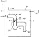
- the vacuum deposition device for high-speed coating 1 may include a vacuum chamber 100, an evaporation crucible 200 disposed in the vacuum chamber 100 to evaporate a coating material, and a cyclone filter 300 separating steam from coarse particles, a connection unit 400 connecting the evaporation crucible 200 with the cyclone filter 300, baffles 500 and 500a connected to one side of the cyclone filter 300 to prevent circulation of steam, and a steam guide unit 600 guiding the steam passing through the baffles 500 and 500a to be sprayed onto the plating target object 2.
- a substrate may be used as the plating target object 2, but the embodiment is not limited thereto.
- the vacuum chamber 100 forms appearance of the vacuum deposition device for high-speed coating 1 and may include a reception space S formed therein.
- the reception space S may accommodate the evaporation crucible 200, the cyclone filter 300, the connection unit 400, the baffles 500 and 500a, and the steam guide unit 600.
- the evaporation crucible 200 may generate steam by evaporating the coating material.
- a resistive heating or electromagnetic levitation heating method may be used as the method of evaporating steam.
- metals such as zinc, magnesium, aluminum, and the like, may be used as the coating material.
- the steam and the coarse particles may be transferred to the cyclone filter 300 through the connection unit 400.
- connection unit 400 connects the evaporation crucible 200 with the cyclone filter 300, but the embodiment is not limited thereto.
- one side of the evaporation crucible 200 may be connected with an inlet 311 of the cyclone filter 300 without the connection unit 400. Therefore, the steam and the coarse particles generated in the evaporation crucible 200 may be transferred to the inlet 311 of the cyclone filter 300.
- the cyclone filter 300 may separate the steam from the coarse particles in a cyclone method.
- the cyclone filter 300 may include a cylindrical cyclone filter main body 310 and a collecting part 320 disposed under the cyclone filter main body 310.
- the cyclone filter main body 310 may include the inlet 311 formed at a side surface thereof and an outlet 312 formed at an upper portion thereof.
- the collecting part 320 may have a tapered shape in which an upper portion is wider than a lower portion.
- the inlet 311 may be disposed to communicate with the connection unit 400. As shown in FIG. 2 , the inlet 311 may be disposed at the side surface of the cyclone filter main body 310. The inlet 311 may have one surface arranged on the cyclone filter main body 310 in a tangent plane manner.
- the cyclone filter main body 310 may include the outlet 312 formed therein and may further include an inner part 313 extending downward.
- the steam and the coarse particles introduced into the cyclone filter 300 through the inlet 311 rotate along an inner surface of the cyclone filter 300 and an outer surface of the inner part 313.
- the inner part 313 may have a cylindrical shape with a predetermined diameter D2.
- a diameter D2 of the outlet 312 may be in a range of 0.2 to 0.8, and a diameter D3 of a bottom of the collecting part 320 may be in a range of 0.1 to 0.8.
- a height H1 of the cyclone filter main body 310 may be in a range of 0.3 to 5, and a height H2 of the collecting part 320 may be in a range of 0.3 to 1.0.
- a height H3 of the inlet 311 may be in a range of 0.2 to 1, and a width W of the inlet 311 may be in a range of 0.1 to 0.5.
- the steam with a particle diameter of 1 ⁇ m is discharged through the outlet 312, and is sprayed onto the plating target object 2 through an injection hole 610. Further, the coarse particles with a diameter of 5 ⁇ m are removed by the cyclone filter 300.
- Simulation results shown in FIG. 5 are examples, but a size of the removable coarse particle may vary according to a design of a cyclone.
- the baffles 500 and 500a are connected to the outlet 312 of the cyclone filter 300 to have high coating uniformity of the plating target object 2 and may prevent circulation of the steam.
- FIG. 6 is a view showing an example of a baffle of the vacuum deposition device for high-speed coating according to one embodiment of the present invention.
- the baffle 500 may include a plurality of horizontal plates 510 separated from each other at predetermined distances and a plurality of vertical plates 520 separated from each other at predetermined distances.
- the horizontal plates 510 are separated from each other at the predetermined distances, and the plurality of vertical plates 520 may be separated from each other in a direction perpendicular to the horizontal plates 510.
- the horizontal plates 510 and the vertical plates 520 may be integrally formed.
- the baffle 500 has a plurality of lattice shapes formed therein and a plurality of protrusions protruding outward with respect to the lattices.
- FIG. 7 is a view showing another example of the baffle of the vacuum deposition device for high-speed coating according to one embodiment of the present invention.
- the baffle 500a may include a plurality of plates 530.
- the plurality of plates 530 may be separated from each other in a circumferential direction with respect to a virtual line C.
- the steam guide unit 600 guides the steam which is prevented from rotating by the baffles 500 and 500a, and allows the steam to be sprayed onto the plating target object 2 through the injection hole 610.
- the steam is sprayed through the injection hole 610, but the embodiment is not limited thereto.
- a nozzle (not shown) may be disposed at the injection hole 610 to allow the steam to be uniformly sprayed.
- the cyclone filter 300, the connection unit 400, the baffles 500 and 500a, the steam guide unit 600, and the like should be heated to temperatures higher than a temperature at which the steam does not condense.
- a heating unit 700 of the vacuum deposition device for high-speed coating 1 heats the reception space S to the temperature at which the steam does not condense or higher to prevent the steam from being condensed.
- the heating unit 700 heats the reception space S of the vacuum chamber 100 to a predetermined temperature, but the embodiment is not limited thereto.
- the heating unit 700 may be installed to heat the cyclone filter 300, the connection unit 400, the baffles 500 and 500a, the steam guide unit 600, and the like.
Landscapes
- Chemical & Material Sciences (AREA)
- Chemical Kinetics & Catalysis (AREA)
- Engineering & Computer Science (AREA)
- Materials Engineering (AREA)
- Mechanical Engineering (AREA)
- Metallurgy (AREA)
- Organic Chemistry (AREA)
- Physical Vapour Deposition (AREA)
Applications Claiming Priority (2)
| Application Number | Priority Date | Filing Date | Title |
|---|---|---|---|
| KR1020150185053A KR101777777B1 (ko) | 2015-12-23 | 2015-12-23 | 고속 코팅용 진공 증착 장치 |
| PCT/KR2016/014637 WO2017111384A1 (fr) | 2015-12-23 | 2016-12-14 | Dispositif de dépôt sous vide pour revêtement à grande vitesse |
Publications (2)
| Publication Number | Publication Date |
|---|---|
| EP3396014A1 true EP3396014A1 (fr) | 2018-10-31 |
| EP3396014A4 EP3396014A4 (fr) | 2018-12-19 |
Family
ID=59090756
Family Applications (1)
| Application Number | Title | Priority Date | Filing Date |
|---|---|---|---|
| EP16879251.3A Withdrawn EP3396014A4 (fr) | 2015-12-23 | 2016-12-14 | Dispositif de dépôt sous vide pour revêtement à grande vitesse |
Country Status (6)
| Country | Link |
|---|---|
| US (1) | US20190015845A1 (fr) |
| EP (1) | EP3396014A4 (fr) |
| JP (1) | JP2018537591A (fr) |
| KR (1) | KR101777777B1 (fr) |
| CN (1) | CN108474103A (fr) |
| WO (1) | WO2017111384A1 (fr) |
Cited By (1)
| Publication number | Priority date | Publication date | Assignee | Title |
|---|---|---|---|---|
| EP3824112A1 (fr) * | 2018-08-10 | 2021-05-26 | First Solar, Inc. | Systèmes et procédés de vaporisation et de distribution de vapeur |
Families Citing this family (4)
| Publication number | Priority date | Publication date | Assignee | Title |
|---|---|---|---|---|
| CN107177830A (zh) * | 2017-07-13 | 2017-09-19 | 安徽省宁国市海伟电子有限公司 | 全铝型金属化薄膜及其真空镀膜装置 |
| CN107254663A (zh) * | 2017-07-13 | 2017-10-17 | 安徽省宁国市海伟电子有限公司 | 一种抗氧化型真空镀膜装置 |
| CN110106471B (zh) * | 2019-06-18 | 2021-01-22 | 京东方科技集团股份有限公司 | 一种导流机构、坩埚装置、蒸镀设备及蒸镀方法 |
| KR102292575B1 (ko) * | 2019-12-16 | 2021-08-24 | 주식회사 포스코 | 연속 코팅 장치 |
Family Cites Families (17)
| Publication number | Priority date | Publication date | Assignee | Title |
|---|---|---|---|---|
| US3447951A (en) * | 1965-10-20 | 1969-06-03 | Pennsalt Chemicals Corp | Cyclone separation of particles in vapor coating |
| US3517643A (en) * | 1968-11-25 | 1970-06-30 | Sylvania Electric Prod | Vapor deposition apparatus including diffuser means |
| US4017354A (en) * | 1976-05-04 | 1977-04-12 | Alexandr Nikolaevich Marchenko | Rotary film evaporating apparatus |
| JPS58224167A (ja) * | 1982-06-22 | 1983-12-26 | Mitsubishi Heavy Ind Ltd | 真空蒸着装置 |
| US6409839B1 (en) * | 1997-06-02 | 2002-06-25 | Msp Corporation | Method and apparatus for vapor generation and film deposition |
| KR100532034B1 (ko) * | 2000-03-10 | 2005-11-30 | 주식회사 엘지이아이 | 플라즈마중합처리장치의 필터링 시스템 |
| KR20030030757A (ko) * | 2001-10-12 | 2003-04-18 | 주식회사 엘지이아이 | 플라즈마 중합장비의 배기가스 필터링장치 |
| KR100477546B1 (ko) * | 2002-07-24 | 2005-03-18 | 주식회사 소로나 | 유기물질 증착방법 및 이를 적용한 장치 |
| US7122085B2 (en) * | 2002-07-30 | 2006-10-17 | Asm America, Inc. | Sublimation bed employing carrier gas guidance structures |
| US6936086B2 (en) * | 2002-09-11 | 2005-08-30 | Planar Systems, Inc. | High conductivity particle filter |
| KR100598717B1 (ko) | 2004-02-23 | 2006-07-11 | 엘지전자 주식회사 | 불균일하게 배치된 가열수단을 포함하는 유기 전계 발광소자의 증착원 |
| JP4768584B2 (ja) * | 2006-11-16 | 2011-09-07 | 財団法人山形県産業技術振興機構 | 蒸発源およびこれを用いた真空蒸着装置 |
| JP2010087169A (ja) * | 2008-09-30 | 2010-04-15 | Tokyo Electron Ltd | 気化器およびそれを用いた成膜装置 |
| US20160312356A1 (en) * | 2013-12-19 | 2016-10-27 | Posco | Heating apparatus and coating machine having same |
| CN107109626B (zh) * | 2014-09-18 | 2020-07-28 | 蒂森克虏伯钢铁欧洲股份公司 | 用于在部件的表面上形成涂层的装置 |
| KR101507055B1 (ko) | 2014-12-05 | 2015-04-01 | 대한민국 | 싸이클론 집진식 선박용 배기가스 저감필터 |
| JP2020512486A (ja) * | 2017-03-22 | 2020-04-23 | ユニバーシティー、オブ、デラウェアUniversity Of Delaware | 遠心蒸発源 |
-
2015
- 2015-12-23 KR KR1020150185053A patent/KR101777777B1/ko not_active Expired - Fee Related
-
2016
- 2016-12-14 WO PCT/KR2016/014637 patent/WO2017111384A1/fr not_active Ceased
- 2016-12-14 US US16/065,313 patent/US20190015845A1/en not_active Abandoned
- 2016-12-14 CN CN201680075464.6A patent/CN108474103A/zh active Pending
- 2016-12-14 JP JP2018530736A patent/JP2018537591A/ja active Pending
- 2016-12-14 EP EP16879251.3A patent/EP3396014A4/fr not_active Withdrawn
Cited By (1)
| Publication number | Priority date | Publication date | Assignee | Title |
|---|---|---|---|---|
| EP3824112A1 (fr) * | 2018-08-10 | 2021-05-26 | First Solar, Inc. | Systèmes et procédés de vaporisation et de distribution de vapeur |
Also Published As
| Publication number | Publication date |
|---|---|
| US20190015845A1 (en) | 2019-01-17 |
| CN108474103A (zh) | 2018-08-31 |
| JP2018537591A (ja) | 2018-12-20 |
| KR101777777B1 (ko) | 2017-09-26 |
| KR20170075422A (ko) | 2017-07-03 |
| EP3396014A4 (fr) | 2018-12-19 |
| WO2017111384A1 (fr) | 2017-06-29 |
Similar Documents
| Publication | Publication Date | Title |
|---|---|---|
| EP3396014A1 (fr) | Dispositif de dépôt sous vide pour revêtement à grande vitesse | |
| EP2168644B1 (fr) | Évaporateur pour matériaux organiques et procédé pour l'évaporation de matériaux organiques | |
| US20180037982A1 (en) | Linear evaporation source and deposition apparatus including the same | |
| US3329524A (en) | Centrifugal-type vapor source | |
| US8435352B2 (en) | Apparatus and method for coating a substrate | |
| EP3234214B1 (fr) | Dispositif de filtration pour éliminer des particules d'un flux de vapeur | |
| RU2755323C1 (ru) | Установка для вакуумного осаждения покрытий и способ нанесения покрытий на подложку | |
| KR102157819B1 (ko) | 열 최적화 링들 | |
| US11492695B2 (en) | Vacuum deposition facility and method for coating a substrate | |
| JP7376426B2 (ja) | 真空蒸着装置用の蒸着源 | |
| JP2023075126A (ja) | 真空チャンバ内で基板をコーティングするための気相堆積装置及び方法 | |
| CA1264613A (fr) | Methode et dispositif de metallisation de feuilles dans une machine de calandrage sous vide | |
| CN111479950B (zh) | 真空沉积设备和用于涂覆基底的方法 | |
| CN223118532U (zh) | 一种用于蒸发源的坩埚 | |
| US20250003052A1 (en) | Coating source, coating installation and method for coating substrates | |
| CN111479949B (zh) | 真空沉积设备和用于涂覆基底的方法 | |
| JP7503398B2 (ja) | 真空成膜装置用の部品 | |
| BR112020025193B1 (pt) | Método para depositar continuamente, sobre um substrato em movimento (s), revestimentos formados a partir de pelo menos um metal, substrato de metal e instalação de deposição a vácuo | |
| BR112020010757B1 (pt) | Instalação de deposição a vácuo, processo para depositar continuamente e kit para montagem de uma instalação de deposição a vácuo | |
| DE10345936A1 (de) | Elektronenstrahl-Beschichtungsanlage zum Aufbringen keramischer Werkstoffe |
Legal Events
| Date | Code | Title | Description |
|---|---|---|---|
| STAA | Information on the status of an ep patent application or granted ep patent |
Free format text: STATUS: THE INTERNATIONAL PUBLICATION HAS BEEN MADE |
|
| PUAI | Public reference made under article 153(3) epc to a published international application that has entered the european phase |
Free format text: ORIGINAL CODE: 0009012 |
|
| STAA | Information on the status of an ep patent application or granted ep patent |
Free format text: STATUS: REQUEST FOR EXAMINATION WAS MADE |
|
| 17P | Request for examination filed |
Effective date: 20180618 |
|
| AK | Designated contracting states |
Kind code of ref document: A1 Designated state(s): AL AT BE BG CH CY CZ DE DK EE ES FI FR GB GR HR HU IE IS IT LI LT LU LV MC MK MT NL NO PL PT RO RS SE SI SK SM TR |
|
| AX | Request for extension of the european patent |
Extension state: BA ME |
|
| A4 | Supplementary search report drawn up and despatched |
Effective date: 20181115 |
|
| RIC1 | Information provided on ipc code assigned before grant |
Ipc: C23C 14/24 20060101AFI20181109BHEP Ipc: C23C 14/02 20060101ALI20181109BHEP Ipc: B01D 45/16 20060101ALI20181109BHEP Ipc: C23C 14/54 20060101ALI20181109BHEP |
|
| DAV | Request for validation of the european patent (deleted) | ||
| DAX | Request for extension of the european patent (deleted) | ||
| STAA | Information on the status of an ep patent application or granted ep patent |
Free format text: STATUS: EXAMINATION IS IN PROGRESS |
|
| 17Q | First examination report despatched |
Effective date: 20190701 |
|
| GRAP | Despatch of communication of intention to grant a patent |
Free format text: ORIGINAL CODE: EPIDOSNIGR1 |
|
| STAA | Information on the status of an ep patent application or granted ep patent |
Free format text: STATUS: GRANT OF PATENT IS INTENDED |
|
| INTG | Intention to grant announced |
Effective date: 20210607 |
|
| STAA | Information on the status of an ep patent application or granted ep patent |
Free format text: STATUS: THE APPLICATION IS DEEMED TO BE WITHDRAWN |
|
| 18D | Application deemed to be withdrawn |
Effective date: 20211019 |