EP3396115A1 - Gasturbinentriebwerk - Google Patents
Gasturbinentriebwerk Download PDFInfo
- Publication number
- EP3396115A1 EP3396115A1 EP17188589.0A EP17188589A EP3396115A1 EP 3396115 A1 EP3396115 A1 EP 3396115A1 EP 17188589 A EP17188589 A EP 17188589A EP 3396115 A1 EP3396115 A1 EP 3396115A1
- Authority
- EP
- European Patent Office
- Prior art keywords
- gas turbine
- turbine engine
- teeth
- torque
- engine according
- Prior art date
- Legal status (The legal status is an assumption and is not a legal conclusion. Google has not performed a legal analysis and makes no representation as to the accuracy of the status listed.)
- Withdrawn
Links
Images




Classifications
-
- F—MECHANICAL ENGINEERING; LIGHTING; HEATING; WEAPONS; BLASTING
- F01—MACHINES OR ENGINES IN GENERAL; ENGINE PLANTS IN GENERAL; STEAM ENGINES
- F01D—NON-POSITIVE DISPLACEMENT MACHINES OR ENGINES, e.g. STEAM TURBINES
- F01D21/00—Shutting-down of machines or engines, e.g. in emergency; Regulating, controlling, or safety means not otherwise provided for
- F01D21/04—Shutting-down of machines or engines, e.g. in emergency; Regulating, controlling, or safety means not otherwise provided for responsive to undesired position of rotor relative to stator or to breaking-off of a part of the rotor, e.g. indicating such position
- F01D21/045—Shutting-down of machines or engines, e.g. in emergency; Regulating, controlling, or safety means not otherwise provided for responsive to undesired position of rotor relative to stator or to breaking-off of a part of the rotor, e.g. indicating such position special arrangements in stators or in rotors dealing with breaking-off of part of rotor
-
- F—MECHANICAL ENGINEERING; LIGHTING; HEATING; WEAPONS; BLASTING
- F01—MACHINES OR ENGINES IN GENERAL; ENGINE PLANTS IN GENERAL; STEAM ENGINES
- F01D—NON-POSITIVE DISPLACEMENT MACHINES OR ENGINES, e.g. STEAM TURBINES
- F01D5/00—Blades; Blade-carrying members; Heating, heat-insulating, cooling or antivibration means on the blades or the members
- F01D5/02—Blade-carrying members, e.g. rotors
- F01D5/06—Rotors for more than one axial stage, e.g. of drum or multiple disc type; Details thereof, e.g. shafts, shaft connections
- F01D5/066—Connecting means for joining rotor-discs or rotor-elements together, e.g. by a central bolt, by clamps
-
- F—MECHANICAL ENGINEERING; LIGHTING; HEATING; WEAPONS; BLASTING
- F02—COMBUSTION ENGINES; HOT-GAS OR COMBUSTION-PRODUCT ENGINE PLANTS
- F02K—JET-PROPULSION PLANTS
- F02K3/00—Plants including a gas turbine driving a compressor or a ducted fan
- F02K3/02—Plants including a gas turbine driving a compressor or a ducted fan in which part of the working fluid by-passes the turbine and combustion chamber
- F02K3/04—Plants including a gas turbine driving a compressor or a ducted fan in which part of the working fluid by-passes the turbine and combustion chamber the plant including ducted fans, i.e. fans with high volume, low pressure outputs, for augmenting the jet thrust, e.g. of double-flow type
- F02K3/06—Plants including a gas turbine driving a compressor or a ducted fan in which part of the working fluid by-passes the turbine and combustion chamber the plant including ducted fans, i.e. fans with high volume, low pressure outputs, for augmenting the jet thrust, e.g. of double-flow type with front fan
-
- F—MECHANICAL ENGINEERING; LIGHTING; HEATING; WEAPONS; BLASTING
- F05—INDEXING SCHEMES RELATING TO ENGINES OR PUMPS IN VARIOUS SUBCLASSES OF CLASSES F01-F04
- F05D—INDEXING SCHEME FOR ASPECTS RELATING TO NON-POSITIVE-DISPLACEMENT MACHINES OR ENGINES, GAS-TURBINES OR JET-PROPULSION PLANTS
- F05D2220/00—Application
- F05D2220/30—Application in turbines
- F05D2220/36—Application in turbines specially adapted for the fan of turbofan engines
-
- F—MECHANICAL ENGINEERING; LIGHTING; HEATING; WEAPONS; BLASTING
- F05—INDEXING SCHEMES RELATING TO ENGINES OR PUMPS IN VARIOUS SUBCLASSES OF CLASSES F01-F04
- F05D—INDEXING SCHEME FOR ASPECTS RELATING TO NON-POSITIVE-DISPLACEMENT MACHINES OR ENGINES, GAS-TURBINES OR JET-PROPULSION PLANTS
- F05D2250/00—Geometry
- F05D2250/10—Two-dimensional
- F05D2250/13—Two-dimensional trapezoidal
-
- F—MECHANICAL ENGINEERING; LIGHTING; HEATING; WEAPONS; BLASTING
- F05—INDEXING SCHEMES RELATING TO ENGINES OR PUMPS IN VARIOUS SUBCLASSES OF CLASSES F01-F04
- F05D—INDEXING SCHEME FOR ASPECTS RELATING TO NON-POSITIVE-DISPLACEMENT MACHINES OR ENGINES, GAS-TURBINES OR JET-PROPULSION PLANTS
- F05D2250/00—Geometry
- F05D2250/10—Two-dimensional
- F05D2250/18—Two-dimensional patterned
- F05D2250/182—Two-dimensional patterned crenellated, notched
-
- F—MECHANICAL ENGINEERING; LIGHTING; HEATING; WEAPONS; BLASTING
- F05—INDEXING SCHEMES RELATING TO ENGINES OR PUMPS IN VARIOUS SUBCLASSES OF CLASSES F01-F04
- F05D—INDEXING SCHEME FOR ASPECTS RELATING TO NON-POSITIVE-DISPLACEMENT MACHINES OR ENGINES, GAS-TURBINES OR JET-PROPULSION PLANTS
- F05D2250/00—Geometry
- F05D2250/10—Two-dimensional
- F05D2250/18—Two-dimensional patterned
- F05D2250/183—Two-dimensional patterned zigzag
-
- F—MECHANICAL ENGINEERING; LIGHTING; HEATING; WEAPONS; BLASTING
- F05—INDEXING SCHEMES RELATING TO ENGINES OR PUMPS IN VARIOUS SUBCLASSES OF CLASSES F01-F04
- F05D—INDEXING SCHEME FOR ASPECTS RELATING TO NON-POSITIVE-DISPLACEMENT MACHINES OR ENGINES, GAS-TURBINES OR JET-PROPULSION PLANTS
- F05D2250/00—Geometry
- F05D2250/10—Two-dimensional
- F05D2250/18—Two-dimensional patterned
- F05D2250/184—Two-dimensional patterned sinusoidal
-
- F—MECHANICAL ENGINEERING; LIGHTING; HEATING; WEAPONS; BLASTING
- F05—INDEXING SCHEMES RELATING TO ENGINES OR PUMPS IN VARIOUS SUBCLASSES OF CLASSES F01-F04
- F05D—INDEXING SCHEME FOR ASPECTS RELATING TO NON-POSITIVE-DISPLACEMENT MACHINES OR ENGINES, GAS-TURBINES OR JET-PROPULSION PLANTS
- F05D2260/00—Function
- F05D2260/30—Retaining components in desired mutual position
- F05D2260/31—Retaining bolts or nuts
- F05D2260/311—Retaining bolts or nuts of the frangible or shear type
-
- F—MECHANICAL ENGINEERING; LIGHTING; HEATING; WEAPONS; BLASTING
- F05—INDEXING SCHEMES RELATING TO ENGINES OR PUMPS IN VARIOUS SUBCLASSES OF CLASSES F01-F04
- F05D—INDEXING SCHEME FOR ASPECTS RELATING TO NON-POSITIVE-DISPLACEMENT MACHINES OR ENGINES, GAS-TURBINES OR JET-PROPULSION PLANTS
- F05D2260/00—Function
- F05D2260/30—Retaining components in desired mutual position
- F05D2260/36—Retaining components in desired mutual position by a form fit connection, e.g. by interlocking
-
- F—MECHANICAL ENGINEERING; LIGHTING; HEATING; WEAPONS; BLASTING
- F05—INDEXING SCHEMES RELATING TO ENGINES OR PUMPS IN VARIOUS SUBCLASSES OF CLASSES F01-F04
- F05D—INDEXING SCHEME FOR ASPECTS RELATING TO NON-POSITIVE-DISPLACEMENT MACHINES OR ENGINES, GAS-TURBINES OR JET-PROPULSION PLANTS
- F05D2260/00—Function
- F05D2260/40—Transmission of power
- F05D2260/403—Transmission of power through the shape of the drive components
-
- F—MECHANICAL ENGINEERING; LIGHTING; HEATING; WEAPONS; BLASTING
- F05—INDEXING SCHEMES RELATING TO ENGINES OR PUMPS IN VARIOUS SUBCLASSES OF CLASSES F01-F04
- F05D—INDEXING SCHEME FOR ASPECTS RELATING TO NON-POSITIVE-DISPLACEMENT MACHINES OR ENGINES, GAS-TURBINES OR JET-PROPULSION PLANTS
- F05D2260/00—Function
- F05D2260/40—Transmission of power
- F05D2260/403—Transmission of power through the shape of the drive components
- F05D2260/4031—Transmission of power through the shape of the drive components as in toothed gearing
- F05D2260/40311—Transmission of power through the shape of the drive components as in toothed gearing of the epicyclical, planetary or differential type
Definitions
- the invention relates to a gas turbine engine with the features of claim 1.
- Gas turbine engines in particular aircraft engines with geared turbofan arrangements, require some means to mitigate damages that might occur after a failure.
- a failure might involve the rotation prevention of at least one part of the drive train. Such a failure might be e.g. a shaft breaking, a rotor-casing contact or a bearing seizure. This becomes even more important for high bypass ratio engines in which the drag of a locked fan would be considerable. Under an extreme event an excessive torque is experienced in the non-nominal rotation direction.
- the gas turbine engine comprises a torque transmission device connecting two co-axial parts, in particular co-axial shafts in the drive train, the torque transmission device having a defined torque transmission characteristic with a face gear connection comprising interlocking frontal teeth designed so that a directional change and / or torque magnitude change deviated from a nominal rotation condition causes a disengagement of the frontal teeth connection.
- one embodiment can comprise a face gear connection with first frontal teeth and second frontal teeth, the teeth being symmetric relative to a rotational axis.
- symmetric teeth are teeth, formed as a Hirth Coupling or a curvic coupling.
- the face gear connection of the torque transmission device comprises first frontal teeth and second frontal teeth, the teeth being asymmetric relative to a rotational axis.
- the face gear connection can comprise the asymmetric teeth inducing an axial load under torque.
- An example for asymmetric teeth are saw-toothed teeth.
- the face gear connection is disengageable after exceeding a predetermined axial load and / or a predetermined differential torque acting on the face gear connection.
- the torque transmission device can comprise at least one mechanical fuse and / or is coupled to at least one mechanical fuse to break under a predetermined torque transmitted through the face gear connection.
- the mechanical fuse can e.g. comprise at least one pin due to break under a predetermined shear load in the face gear connection. It is also possible that the at least one pin is part of a bolted flange connection, coupled with the face gear connection.
- structural parts of the gas turbine engine in particular the first shaft the second shaft, a fixed structure of the gas turbine engine and / or a link have individually or collectively a predetermined stiffness so that a directional change and / or torque magnitude change deviated from a nominal rotation condition causes a disengagement of the frontal teeth connection of the at least one torque transmission device.
- the gas turbine engine is in one embodiment a geared turbofan arrangement with a gearbox in a drive train driven by a turbine, a driving side of the gearbox being driveably connected with a propulsive fan.
- the transmission device can e.g. couple through the gear face connection a propulsive fan and a turbine, a propulsive fan and an output side of a gearbox and / or an input side of a gearbox and turbine.
- the at least one torque transmission device is located on the output side of the gearbox, i.e. in particular the planetary gearbox.
- Embodiments can be in particular configured as a geared turbofan engine of an aircraft.
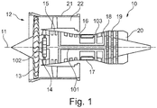
- a gas turbine engine is generally indicated at 10, having a principal and rotational axis 11.
- the engine 10 comprises, in axial flow series, an air intake 12, a propulsive fan 13 (could be more than one stage), a gearbox 14, an intermediate pressure compressor 15, a high-pressure compressor 16, a combustion equipment 17, a high-pressure turbine 18, an intermediate-pressure turbine 19 and an exhaust nozzle 20.
- a fan casing 21 generally surrounds the engine 10 and defines the intake 12.
- the gas turbine engine 10 works in the conventional manner so that air entering the intake 12 is accelerated by the propulsive fan 13 to produce two air flows: a first air flow into the intermediate pressure compressor 15 and a second air flow which passes through a bypass duct 22 to provide propulsive thrust.
- the intermediate pressure compressor 15 compresses the air flow directed into it before delivering that air to the high pressure compressor 16 where further compression takes place.
- the compressed air exhausted from the high-pressure compressor 16 is directed into the combustion equipment 17 where it is mixed with fuel and the mixture is combusted.
- the resultant hot combustion products then expand through, and thereby drive the high pressure turbine 18 and intermediate pressure turbine 19 before being exhausted through the nozzle 20 to provide additional propulsive thrust.
- An intermediate pressure shaft 101 also drives the propulsive fan 13 via the gearbox 14.
- the gearbox 14 is a reduction gearbox in that it gears down the rate of rotation of the propulsive fan 13 by comparison with the intermediate pressure compressor 15 and intermediate pressure turbine 19.
- the gearbox 14 is an epicyclic planetary gearbox having a static ring gear, rotating and orbiting planet gears supported by a planet carrier and a rotating sun gear 102.
- the output of the gearbox 14 is through the carrier. In principle other gearbox 14 designs can be used.
- Fig. 1 has a specific shaft arrangement which is understood not to be limiting.
- the embodiments described in the following can also work with a 2- or 3-shaft arrangement.
- geared turbofan engines 10 are known in the art. With increasing power ratings and / or increasing diameters of the propulsive fans 13, the loads on the gas turbine engines 10 are increasing. Therefore, it seems advisable to introduce measures to counteract potential failure modes or extreme events such as e.g. a fan blade off, a core blade off, a bird strike, a surge load, a mainline bearing seizure or an event at the gearbox 14.
- a torque transmission device 60 having a defined torque transmission characteristic are described below. It should be noted that the embodiments can be applied to gas turbo engines other than geared turbofan engines.
- the embodiments of the torque transmission devices 60 use face gear connection comprising interlocking frontal teeth 61, 62 to connect co-axial shafts 1, 2.
- This face gear connection 61, 62 designed such that a directional change and / or a torque magnitude change deviating from a nominal rotation condition causes a disengagement of the frontal teeth connection 61, 62.
- This means that the face gear connection 61, 62 can react to a change in rotation and / or significantly higher torque indicating an extreme event by disengaging the shafts 1, 2.
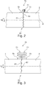
- Fig. 2 a connection of two co-axial shafts 1, 2 is schematically shown.
- the shafts 1, 2 are shown here as cylindrically shaped bodies.
- the shafts 1, 2 can have a much more complex shape, in particular in the radial direction.
- the torque transmission device 60 here comprises a face gear connection with teeth 61, 62 extending in axial direction, formlocking with each other.
- the teeth 61, 62 in this embodiment are symmetrical to a rotation axis R with the nominal rotation direction N indicated by an arrow.
- the teeth 61, 62 have a triangular cross section with linear walls, which is also called a Hirth Coupling.
- a mechanical fuse 70 is schematically shown. For the sake of simplicity only one mechanical fuse 70 is shown here.
- a plurality of mechanical fuses 70 are positioned around the circumference of the shafts 1, 2 in a symmetrical way, i.e. the mechanical fuses 70 have an identical angular distance to each other.
- the mechanical fuse 70 comprises a flange, with flange elements 72, 73 being positioned axially on either side of the face gear connection 61, 62.
- the flange elements 72, 73 are connected by a bolt (or pin) 71 which here is extending in axial direction.
- the face gear connection 61, 62 ensures the reliable transmission of torque. Under excessive torque conditions, i.e. with a torque being much higher than the nominal torque, the toothed formlocking face gear connection 61, 62 as well as the mechanical fuse 70 fail under this predefined overtorque transmitted through the face gear connection 61, 62; i.e. the shafts 1, 2 disengage.
- Fig. 3 a variation of the embodiment depicted in Fig. 2 is shown so that reference can be made to the respective description above.
- This embodiment used curvic teeth instead of triangular shaped teeth.
- the curvic face gear connection comprises teeth 61, 62 in an axially symmetric spacing.
- the cross section of the teeth is curved and not straight as in the embodiment shown in Fig. 2 .
- the curvic face gear connection 61, 62 is just another way in connecting two co-axial shafts 1, 2 through axially oriented teeth 61, 62.
- the embodiment shown in Fig. 3 also comprises a mechanical fuse 70 using flange elements 72, 73, 74.
- the first and second flange elements 72, 73 - generally having a U-shaped cross section - are positioned on either side of the face gear connection 61, 62.
- the open sides of the U-shaped flange elements 72, 73 point away from the face gear connection 61, 62.
- an outer third flange element 74 extends across both flange elements 72, 72 underneath.
- pins 71, 71' are connecting the outer flange element 74 to the inner flange elements 72, 73.
- the long axes of the pins 71, 71' are here oriented perpendicular to the rotation axis R.
- Fig. 2 and 3 can be used for solid shafts or tubular co-axial shafts 1, 2.
- FIG. 4 shows a face gear connection 61, 62 with tubular shafts 1, 2.
- the flange elements 72, 73 of the mechanical fuses 70 are here located at the inside of the shafts 1, 2.
- the pins 71 are positioned in an axial way.
- the curvic teeth 61, 62 are symmetric with respect to the rotating axis R.
- Fig. 5 an embodiment with a face gear connection with asymmetric shaped teeth 61, 62 is shown.
- the saw-tooth shaped teeth 61, 62 can transmit torque in one direction and separate the co-axial shafts 1, 2, in case the rotation direction changes.
- the first shaft 1 drives the second shaft 2 in the nominal rotation direction N.
- the axial force A generated by the sloped teeth 61, 62 is indicated.
- the amount of torque required to disengage the face gear connection 61, 62 can be controlled in a number of ways.
- the axial stiffness of the shafts 1, 2 only permits a predetermined axial load.
- An alternative way to control the torque can use a shaft 1 with an end restraint which is free to move axially, or the shaft 1 itself is not restrained in the axial direction.
- the shaft 1 that is free to move axially also experiences a torque from another source, for example a propulsive fan 13. Therefore, two different torques act on the shafts 1, 2.
- a torque transmission device 60 is operating on the output side of the gearbox 14.
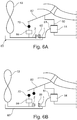
- Fig. 6A and 6B show a front section of the engine 10 with the planetary gearbox 14 in different positions.
- the planetary gearbox 14 comprises a fixed ring gear mount 80 and a torque output via a carrier 81.
- the planetary gearbox 14 is driven through it sun gear.
- the carrier 81 is coupled to the first shaft 1.
- the first shaft 1 and the second shaft 2 are connected through the torque transmission device 60.
- the ring gear mount 80 is connected to some fixed structure 82 of the gas turbine engine 10.
- a mechanical fuse 70 is positioned between the fixed structure 82 and the second shaft 2 and connected to a bearing 84.
- the torque from the carrier is transmitted via the torque transmission device 60 to the second shaft 2 and then to the propulsive fan 13.
- the torque transmission device 60 is coupled with the mechanical fuse 70 which is configured to break under predetermined torque conditions.
- the torque transmission device 60 and the mechanical fuse 70 are in a engaged first position.
- the breaking of the mechanical fuse 70 is shown in Fig. 6B .
- the torque shows a directional change and / or a magnitude change deviating from the nominal rotation condition causing a disengagement of the frontal teeth connection of the torque transmission device.
- the mechanical fuse 70 is broken. Both disengagement events are causing an axial movement of the second shaft 2 and the propulsive fan 13.
- a fan catcher 83 limits the axial movement of the propulsive fan 13 under these non-nominal conditions (i.e. a second position).
- Fig. 7A an engaged first position of the frontal section of the geared turbofan engine 10 as gas turbine engine is shown.
- the planetary gearbox 14 comprises a fixed ring gear mount 80 and a torque output via a carrier 81.
- the carrier 81 is coupled to the first shaft 1.
- the first shaft 1 and the second shaft 2 are connected through the torque transmission device 60.
- the ring gear mount 80 is connected to some fixed structure 82 of the gas turbine engine 10. But in this embodiment no mechanical fuse 70 is used.
- the drive train from the gearbox 14 to the propulsive fan 13 comprises a torque transmission device 60 designed such that a directional change and / or torque magnitude change deviated from a nominal rotation N condition causes a disengagement of the frontal teeth connection 61, 62 of the torque transmission device 60.
- the disengagement is facilitated by the tailored design of the stiffnesses S of structural parts, i.e. the first shaft 1, the second shaft 2, the fixed structure 82 and a link 85 from the fixed structure 82 to the bearing 85.
- the torque transmission takes place via the torque transmission device 60. This means that under nominal conditions the parts 1, 2, 82, 85 are so stiff that the torque cannot open the torque transmission device 60, i.e. there a in a first position.
- the stiffness of the parts 1, 2, 82, 85 is so designed, that the parts 1, 2, 82, 85 are deformed in a controlled manner, so that he torque transmission device 60 is becoming disengaged.
- the shaft 2 has as stiffness which allows the disengagement. In other embodiments the stiffness of two or more parts together allows the disengagement.
- the stiffness of other parts involved on the output side of the gearbox 14 can be specifically tailored to allow a controlled disengagement of the torque transmission device 60.
Landscapes
- Engineering & Computer Science (AREA)
- Mechanical Engineering (AREA)
- General Engineering & Computer Science (AREA)
- Chemical & Material Sciences (AREA)
- Combustion & Propulsion (AREA)
- Retarders (AREA)
- General Details Of Gearings (AREA)
Applications Claiming Priority (1)
| Application Number | Priority Date | Filing Date | Title |
|---|---|---|---|
| EP17168699 | 2017-04-28 |
Publications (1)
| Publication Number | Publication Date |
|---|---|
| EP3396115A1 true EP3396115A1 (de) | 2018-10-31 |
Family
ID=58644948
Family Applications (1)
| Application Number | Title | Priority Date | Filing Date |
|---|---|---|---|
| EP17188589.0A Withdrawn EP3396115A1 (de) | 2017-04-28 | 2017-08-30 | Gasturbinentriebwerk |
Country Status (1)
| Country | Link |
|---|---|
| EP (1) | EP3396115A1 (de) |
Cited By (5)
| Publication number | Priority date | Publication date | Assignee | Title |
|---|---|---|---|---|
| CN109630206A (zh) * | 2018-12-16 | 2019-04-16 | 中国航发沈阳发动机研究所 | 一种多级轮盘转子结构 |
| EP3705704A1 (de) * | 2019-03-06 | 2020-09-09 | Rolls-Royce plc | Wellenvorrichtung für ein gasturbinentriebwerk |
| EP3800379A1 (de) * | 2019-10-03 | 2021-04-07 | Rolls-Royce Corporation | Statische geschweifte dichtung für gehäuseanordnung eines planetengetriebesystems |
| US20210270147A1 (en) * | 2020-02-27 | 2021-09-02 | Rolls-Royce Deutschland Ltd & Co Kg | Torque limiting device in a connection between a gearbox and a stationary structure in a gas turbine engine and a gas turbine engine |
| CN116457553A (zh) * | 2020-11-20 | 2023-07-18 | 赛峰飞机发动机公司 | 装备有密封装置的涡轮发动机转子元件组件 |
Citations (1)
| Publication number | Priority date | Publication date | Assignee | Title |
|---|---|---|---|---|
| FR3022890A1 (fr) * | 2014-06-25 | 2016-01-01 | Snecma | Turbomachine comportant un moyen de decouplage d'une soufflante |
-
2017
- 2017-08-30 EP EP17188589.0A patent/EP3396115A1/de not_active Withdrawn
Patent Citations (1)
| Publication number | Priority date | Publication date | Assignee | Title |
|---|---|---|---|---|
| FR3022890A1 (fr) * | 2014-06-25 | 2016-01-01 | Snecma | Turbomachine comportant un moyen de decouplage d'une soufflante |
Non-Patent Citations (1)
| Title |
|---|
| GLEASON: "Curvic Coupling Design", 1 November 1986 (1986-11-01), XP055459989, Retrieved from the Internet <URL:https://www.geartechnology.com/issues/1186x/Back-to-Basics.pdf> [retrieved on 20180315] * |
Cited By (7)
| Publication number | Priority date | Publication date | Assignee | Title |
|---|---|---|---|---|
| CN109630206A (zh) * | 2018-12-16 | 2019-04-16 | 中国航发沈阳发动机研究所 | 一种多级轮盘转子结构 |
| EP3705704A1 (de) * | 2019-03-06 | 2020-09-09 | Rolls-Royce plc | Wellenvorrichtung für ein gasturbinentriebwerk |
| US11168618B2 (en) | 2019-03-06 | 2021-11-09 | Rolls-Royce Plc | Shaft apparatus for a gas turbine engine |
| EP3800379A1 (de) * | 2019-10-03 | 2021-04-07 | Rolls-Royce Corporation | Statische geschweifte dichtung für gehäuseanordnung eines planetengetriebesystems |
| US20210270147A1 (en) * | 2020-02-27 | 2021-09-02 | Rolls-Royce Deutschland Ltd & Co Kg | Torque limiting device in a connection between a gearbox and a stationary structure in a gas turbine engine and a gas turbine engine |
| US11879383B2 (en) * | 2020-02-27 | 2024-01-23 | Rolls-Royce Deutschland Ltd & Co Kg | Torque limiting device in a connection between a gearbox and a stationary structure in a gas turbine engine and a gas turbine engine |
| CN116457553A (zh) * | 2020-11-20 | 2023-07-18 | 赛峰飞机发动机公司 | 装备有密封装置的涡轮发动机转子元件组件 |
Similar Documents
| Publication | Publication Date | Title |
|---|---|---|
| US10954813B2 (en) | Planetary gearbox system and method for operating a planetary gearbox system | |
| US11391290B2 (en) | Turbomachine comprising a means of uncoupling a fan | |
| EP3396115A1 (de) | Gasturbinentriebwerk | |
| US10753409B2 (en) | Mechanical clutch device and method for operating a mechanical clutch device | |
| EP3296525B1 (de) | Gasturbinenmotor mit getriebe-fan | |
| EP2085586B1 (de) | Niederdruckturbine und entsprechendes Gasturbinentriebwerk | |
| EP3444445A1 (de) | Mechanische sicherungsvorrichtung und verfahren zum betrieb einer mechanischen sicherungsvorrichtung | |
| EP3572637B1 (de) | Gasturbinenmotorkupplungsanordnung | |
| US10669949B2 (en) | Gas turbine engine with a geared turbofan arrangement | |
| US11808212B2 (en) | Drive shaft comprising a fusible section and method for protecting such a drive shaft against an overtorque | |
| EP3296524B1 (de) | Gasturbinenmotor mit getriebefananordnung | |
| EP3121469A1 (de) | Antriebswellenanordnung | |
| EP3396144B1 (de) | Gasturbinenmotor mit getriebefananordnung | |
| EP3882447A1 (de) | Entkoppler für motoranlasser | |
| US10502144B2 (en) | Gas turbine engine with a geared turbofan arrangement | |
| EP3575550A1 (de) | Gasturbinenmotor mit ausfallsicherem wellenschema und entsprechendes verfahren | |
| EP3705704B1 (de) | Wellenvorrichtung für ein gasturbinentriebwerk |
Legal Events
| Date | Code | Title | Description |
|---|---|---|---|
| PUAI | Public reference made under article 153(3) epc to a published international application that has entered the european phase |
Free format text: ORIGINAL CODE: 0009012 |
|
| AK | Designated contracting states |
Kind code of ref document: A1 Designated state(s): AL AT BE BG CH CY CZ DE DK EE ES FI FR GB GR HR HU IE IS IT LI LT LU LV MC MK MT NL NO PL PT RO RS SE SI SK SM TR |
|
| AX | Request for extension of the european patent |
Extension state: BA ME |
|
| STAA | Information on the status of an ep patent application or granted ep patent |
Free format text: STATUS: THE APPLICATION IS DEEMED TO BE WITHDRAWN |
|
| 18D | Application deemed to be withdrawn |
Effective date: 20190501 |