EP3396137B1 - Gasturbinensystem und verfahren zur steuerung davon - Google Patents
Gasturbinensystem und verfahren zur steuerung davon Download PDFInfo
- Publication number
- EP3396137B1 EP3396137B1 EP18168890.4A EP18168890A EP3396137B1 EP 3396137 B1 EP3396137 B1 EP 3396137B1 EP 18168890 A EP18168890 A EP 18168890A EP 3396137 B1 EP3396137 B1 EP 3396137B1
- Authority
- EP
- European Patent Office
- Prior art keywords
- speed regulation
- regulation rate
- power generator
- output
- denotes
- Prior art date
- Legal status (The legal status is an assumption and is not a legal conclusion. Google has not performed a legal analysis and makes no representation as to the accuracy of the status listed.)
- Active
Links
Images

Classifications
-
- F—MECHANICAL ENGINEERING; LIGHTING; HEATING; WEAPONS; BLASTING
- F02—COMBUSTION ENGINES; HOT-GAS OR COMBUSTION-PRODUCT ENGINE PLANTS
- F02C—GAS-TURBINE PLANTS; AIR INTAKES FOR JET-PROPULSION PLANTS; CONTROLLING FUEL SUPPLY IN AIR-BREATHING JET-PROPULSION PLANTS
- F02C9/00—Controlling gas-turbine plants; Controlling fuel supply in air- breathing jet-propulsion plants
- F02C9/26—Control of fuel supply
- F02C9/28—Regulating systems responsive to plant or ambient parameters, e.g. temperature, pressure, rotor speed
-
- H—ELECTRICITY
- H02—GENERATION; CONVERSION OR DISTRIBUTION OF ELECTRIC POWER
- H02P—CONTROL OR REGULATION OF ELECTRIC MOTORS, ELECTRIC GENERATORS OR DYNAMO-ELECTRIC CONVERTERS; CONTROLLING TRANSFORMERS, REACTORS OR CHOKE COILS
- H02P9/00—Arrangements for controlling electric generators for the purpose of obtaining a desired output
- H02P9/04—Control effected upon non-electric prime mover and dependent upon electric output value of the generator
-
- F—MECHANICAL ENGINEERING; LIGHTING; HEATING; WEAPONS; BLASTING
- F01—MACHINES OR ENGINES IN GENERAL; ENGINE PLANTS IN GENERAL; STEAM ENGINES
- F01D—NON-POSITIVE DISPLACEMENT MACHINES OR ENGINES, e.g. STEAM TURBINES
- F01D15/00—Adaptations of machines or engines for special use; Combinations of engines with devices driven thereby
- F01D15/10—Adaptations for driving, or combinations with, electric generators
-
- F—MECHANICAL ENGINEERING; LIGHTING; HEATING; WEAPONS; BLASTING
- F01—MACHINES OR ENGINES IN GENERAL; ENGINE PLANTS IN GENERAL; STEAM ENGINES
- F01D—NON-POSITIVE DISPLACEMENT MACHINES OR ENGINES, e.g. STEAM TURBINES
- F01D21/00—Shutting-down of machines or engines, e.g. in emergency; Regulating, controlling, or safety means not otherwise provided for
- F01D21/003—Arrangements for testing or measuring
-
- F—MECHANICAL ENGINEERING; LIGHTING; HEATING; WEAPONS; BLASTING
- F02—COMBUSTION ENGINES; HOT-GAS OR COMBUSTION-PRODUCT ENGINE PLANTS
- F02C—GAS-TURBINE PLANTS; AIR INTAKES FOR JET-PROPULSION PLANTS; CONTROLLING FUEL SUPPLY IN AIR-BREATHING JET-PROPULSION PLANTS
- F02C7/00—Features, components parts, details or accessories, not provided for in, or of interest apart form groups F02C1/00 - F02C6/00; Air intakes for jet-propulsion plants
- F02C7/22—Fuel supply systems
-
- F—MECHANICAL ENGINEERING; LIGHTING; HEATING; WEAPONS; BLASTING
- F02—COMBUSTION ENGINES; HOT-GAS OR COMBUSTION-PRODUCT ENGINE PLANTS
- F02C—GAS-TURBINE PLANTS; AIR INTAKES FOR JET-PROPULSION PLANTS; CONTROLLING FUEL SUPPLY IN AIR-BREATHING JET-PROPULSION PLANTS
- F02C3/00—Gas-turbine plants characterised by the use of combustion products as the working fluid
- F02C3/04—Gas-turbine plants characterised by the use of combustion products as the working fluid having a turbine driving a compressor
-
- F—MECHANICAL ENGINEERING; LIGHTING; HEATING; WEAPONS; BLASTING
- F05—INDEXING SCHEMES RELATING TO ENGINES OR PUMPS IN VARIOUS SUBCLASSES OF CLASSES F01-F04
- F05D—INDEXING SCHEME FOR ASPECTS RELATING TO NON-POSITIVE-DISPLACEMENT MACHINES OR ENGINES, GAS-TURBINES OR JET-PROPULSION PLANTS
- F05D2220/00—Application
- F05D2220/70—Application in combination with
- F05D2220/76—Application in combination with an electrical generator
- F05D2220/764—Application in combination with an electrical generator of the alternating current (A.C.) type
-
- F—MECHANICAL ENGINEERING; LIGHTING; HEATING; WEAPONS; BLASTING
- F05—INDEXING SCHEMES RELATING TO ENGINES OR PUMPS IN VARIOUS SUBCLASSES OF CLASSES F01-F04
- F05D—INDEXING SCHEME FOR ASPECTS RELATING TO NON-POSITIVE-DISPLACEMENT MACHINES OR ENGINES, GAS-TURBINES OR JET-PROPULSION PLANTS
- F05D2270/00—Control
- F05D2270/01—Purpose of the control system
- F05D2270/02—Purpose of the control system to control rotational speed (n)
- F05D2270/024—Purpose of the control system to control rotational speed (n) to keep rotational speed constant
-
- F—MECHANICAL ENGINEERING; LIGHTING; HEATING; WEAPONS; BLASTING
- F05—INDEXING SCHEMES RELATING TO ENGINES OR PUMPS IN VARIOUS SUBCLASSES OF CLASSES F01-F04
- F05D—INDEXING SCHEME FOR ASPECTS RELATING TO NON-POSITIVE-DISPLACEMENT MACHINES OR ENGINES, GAS-TURBINES OR JET-PROPULSION PLANTS
- F05D2270/00—Control
- F05D2270/01—Purpose of the control system
- F05D2270/05—Purpose of the control system to affect the output of the engine
-
- F—MECHANICAL ENGINEERING; LIGHTING; HEATING; WEAPONS; BLASTING
- F05—INDEXING SCHEMES RELATING TO ENGINES OR PUMPS IN VARIOUS SUBCLASSES OF CLASSES F01-F04
- F05D—INDEXING SCHEME FOR ASPECTS RELATING TO NON-POSITIVE-DISPLACEMENT MACHINES OR ENGINES, GAS-TURBINES OR JET-PROPULSION PLANTS
- F05D2270/00—Control
- F05D2270/01—Purpose of the control system
- F05D2270/06—Purpose of the control system to match engine to driven device
- F05D2270/061—Purpose of the control system to match engine to driven device in particular the electrical frequency of driven generator
-
- F—MECHANICAL ENGINEERING; LIGHTING; HEATING; WEAPONS; BLASTING
- F05—INDEXING SCHEMES RELATING TO ENGINES OR PUMPS IN VARIOUS SUBCLASSES OF CLASSES F01-F04
- F05D—INDEXING SCHEME FOR ASPECTS RELATING TO NON-POSITIVE-DISPLACEMENT MACHINES OR ENGINES, GAS-TURBINES OR JET-PROPULSION PLANTS
- F05D2270/00—Control
- F05D2270/30—Control parameters, e.g. input parameters
- F05D2270/304—Spool rotational speed
-
- F—MECHANICAL ENGINEERING; LIGHTING; HEATING; WEAPONS; BLASTING
- F05—INDEXING SCHEMES RELATING TO ENGINES OR PUMPS IN VARIOUS SUBCLASSES OF CLASSES F01-F04
- F05D—INDEXING SCHEME FOR ASPECTS RELATING TO NON-POSITIVE-DISPLACEMENT MACHINES OR ENGINES, GAS-TURBINES OR JET-PROPULSION PLANTS
- F05D2270/00—Control
- F05D2270/30—Control parameters, e.g. input parameters
- F05D2270/335—Output power or torque
-
- H—ELECTRICITY
- H02—GENERATION; CONVERSION OR DISTRIBUTION OF ELECTRIC POWER
- H02P—CONTROL OR REGULATION OF ELECTRIC MOTORS, ELECTRIC GENERATORS OR DYNAMO-ELECTRIC CONVERTERS; CONTROLLING TRANSFORMERS, REACTORS OR CHOKE COILS
- H02P2101/00—Special adaptation of control arrangements for generators
- H02P2101/25—Special adaptation of control arrangements for generators for combustion engines
Definitions
- the present invention relates to a gas turbine system and a method of controlling the same, and more particularly, to a gas turbine system and a method of controlling the same that the gas turbine system can regulate a reference speed regulation rate that references when a fuel amount control unit controls the amount of fuel supplied to a combustor in order to meet a target speed regulation rate.
- a system or an apparatus having a turbine such as a gas turbine or a steam turbine, as a power generation apparatus converting thermal energy of gas or fluid into a rotation force that is mechanical energy, includes a rotor axially rotated by gas or fluid and a stator supporting and surrounding the rotor.
- the gas turbine used in a power plant for generating electricity can include a compressor supplying high-pressure air that compresses air to a combustor, the combustor for generating combustion gas, and a turbine operated by the combustion gas discharged from the combustor.
- the compressor of the gas turbine is integrally coupled with the shaft of the turbine to axially rotate like the turbine, and sucks and compresses external air while performing the axial rotation.
- the compressed air is supplied to the combustor, and the combustor generates high-temperature, high-pressure combustion gas by supplying fuel to the compressed air to combust the mixture, and supplies it to the turbine.
- the high-temperature, high-pressure combustion gas supplied to the turbine drives a rotary wing of the turbine to rotate the rotor of the turbine.
- the system frequency In the power system supplying electricity, for stable operation of the entire power system, the system frequency needs to be continuously maintained at the rated frequency (60Hz in Korea).
- a plurality of power plants are generally connected to the system to share the power, and if the supply and the load match, the system frequency stabilizes at the rated frequency.
- the supply becomes insufficient and thereby the system frequency is lowered.
- other power plants additionally supply the lacking power to stabilize the system frequency.
- a speed regulation rate as an indicator representing how much power each power plant additionally supplies.
- the speed regulation rate represents the ratio of the rate of change of frequency to the rate of change of output of power generator as a percentage.
- the power plant will additionally supply the power depending on the speed regulation rate, but the actually measured speed regulation rate cannot reach the target speed regulation rate due to a time difference in the control response time and errors in the control logic, etc.
- the power to be additionally supplied does not meet the requirements, and thereby there is the problem in maintaining the system frequency at the rated frequency.
- EP 3 054 129 A1 discloses a correction system and method for gas turbine proportional droop governor.
- the method includes receiving a turbine system operating parameter.
- the turbine system operating parameter includes an indication of a frequency variation of an electric power system associated with the turbine system.
- the method includes determining a correction factor to vary the output of the turbine system according to the frequency variation, wherein the correction factor is based on a droop power response and a nominal droop power ratio.
- the droop power response is calculated based on a gas turbine power output and a speed-load error.
- the method further includes varying the output of the turbine system based at least in part on the correction factor.
- US 2014/260293 A1 discloses systems and methods of droop response control of turbines.
- the system includes a controller configured to control an operational behavior of a turbine system.
- the controller includes a droop response system configured to detect one or more operational characteristics of the turbine system as an indication of a frequency variation of an electric power system associated with the turbine system.
- the droop response system is further configured to generate a response to vary an output of the turbine system in response to the indication of the frequency variation.
- the controller includes a multivariable droop response correction system configured to determine one or more possible errors associated with the one or more operational characteristics of the turbine system, and to generate a plurality of correction factors to apply to the response generated by the droop response system.
- the plurality of correction factors is configured to correct the response generated by the droop response system.
- GB 2019618 A discloses speed regulators for gas turbine-generator sets.
- the object of the present invention is to provide a gas turbine system and a method of controlling the same in which a fuel amount control unit can control a reference speed regulation rate based on the measured actual speed regulation rate, in order to meet the target speed regulation rate.
- a gas turbine control device for a gas turbine system according to claim 1 is disclosed.
- any one part is “on” the other part, it may mean that the part is directly on the other part or any other part is interposed therebetween. On the contrary, when it is described that any one part is “directly on” the other part, there is no other part interposed therebetween.
- first,” “second,” “third” and the like are used to illustrate various parts, components, areas, layers and/or sections, but are not limited thereto. The terms are only used to differentiate a certain part, component, area, layer or section from other part, component, area, layer or section. Accordingly, a first part, component, area, layer or section, which will be mentioned hereinafter, may be referred to as a second part, component, area, layer or section without departing from the scope of the present invention.
- FIG. 1 illustrates a gas turbine system in accordance with one embodiment of the present invention.
- the gas turbine system may include a compressor 10, a turbine 20, a combustor 30, a shaft 40, a power generator 50, and a control apparatus 100.
- the compressor 10 may perform a function of producing high-pressure compressed air by sucking and compressing external air.
- the compressed air may be transferred to the combustor 30.
- the combustor 30 may inject fuel into the compressed air transferred from the compressor 10 and combust the fuel-air mixture to generate high-pressure, high-temperature combustion gas for output to the turbine 20.
- the high-pressure, high-temperature combustion gas supplied to the turbine 20 rotates rotor blades of the turbine, thereby rotating a rotor of the turbine 20.
- the temperature and pressure of the combustion gas supplied to the turbine 20 are lowered while the combustion gas drives the rotor blades of the turbine. Then, the combustion gas is discharged as exhaust gas to the atmosphere.
- the power generator 50 may generate power using the rotation of the rotor of the turbine 20.
- the control device 100 can generally perform various controls for efficient driving of the gas turbine system.
- a method for regulating the rotational speed of the rotor of the turbine 20 may be divided into a load limit control method and a governor free control method.
- the load limit control method refers to a method that fixes the rotational speed of the rotor of the turbine 20 at a constant speed
- the governor free control method refers to a method that automatically controls the rotational speed of the rotor of the turbine 20 according to a frequency change of a power system.
- a system frequency for stable operation of the entire power system needs to be retained at the rated frequency (60Hz in the case of Korea). Therefore, in consideration of facility protection, operators of gas turbine systems prefer the load limit control method, which can prevent a sudden fluctuation of the gas turbine system.
- the speed regulation rate refers to a percentage ratio of a frequency change rate (a change rate of the rotor rotation speed of the turbine 20) to a change rate of the power of the power generator 80.
- the speed regulation rate refers to a percentage ratio of a frequency change rate (a change rate of the rotor rotation speed of the turbine 20) to a change rate of the power of the power generator 80.
- Equation 1 N 1 ⁇ N 2 N N ⁇ P N P 2 ⁇ P 1 ⁇ 100
- Equation 2 P 1 + P N ⁇ N 1 ⁇ N 2 N N ⁇ 100
- N 1 , N 2 and N N are rotor speed values (expressed in revolutions per minute, or rpm) of the turbine 20, and P 1 , P 2 and P N are power values of the power generator 80. More specifically, N 1 denotes the immediately previous rotor speed, N 2 denotes the current rotor speed, N N denotes the rated rotor speed, P 1 denotes the previous power of the power generator 80, P 2 denotes a power that the power generator should generate when the rotor speed changes from N 1 to N 2 , and P N denotes the rated power.
- the system frequency may undergo a sudden drop from the rated frequency due to an event occurring in the system, and arbitrary values associated with the event may be a speed regulation rate ⁇ of 3%, a rated power P N of 28.8MW, a previous power P 1 of 21.6MW, and a system frequency drop to 59.7Hz from a rated frequency of 60Hz.
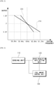
- FIG. 2 shows two outputs (210, 220) of the power generator 50 depending on the system frequency, at two different speed regulation rates, respectively. That is, a line 220 represents the case that the speed regulation rate is 2%, and a line 210 represents the case that the speed regulation rate is 4%.
- the power generator produces an output P. Meanwhile, if the system frequency drops below the rated frequency, the output to be produced depending on the speed regulation rate should be increased, and if the system frequency exceeds the rated frequency, the output to be produced depending on the speed regulation rate should be decreased. Therefore, for a speed regulation rate of 2%, the power generator should produce 1.5 times the output (P) at the rated frequency when the rate of change of the frequency has changed by 1% (0.6Hz), and for a speed regulation rate of 4%, the power generator should produce 1.5 times the output (P) at the rated frequency when the rate of change of the frequency has changed by 2% (1.2Hz). That is, it can be seen that the output to be produced should be changed more sharply for lower speed regulation rates.
- the amount of fuel supplied to the combustor 30 should be increased to generate more high-temperature, high-pressure combustion gas.
- the control device 100 of the present invention can control the amount of fuel supplied to the combustor 30 in order to meet the above-described target speed regulation rate.
- the amount of compressed air supplied from the compressor 10 to the combustor 30 can be also controlled.
- Other control elements on other gas turbine systems can be also controlled.
- control device 100 is designed to adaptively achieve the target speed regulation rate.
- FIG. 3 shows the control device 100 in accordance with one embodiment of the present invention.
- control device 100 may include a sensing unit 110, a speed regulation rate setting unit 120, and a fuel amount control unit 130.
- the sensing unit 110 may measure the rotor speed of the turbine 20 and the output of the power generator 50. As described above, since the rotor speed of the turbine 20 is proportional to the system frequency, the change of the system frequency may be recognized by measuring the rotor speed of the turbine 20, specifically, by counting the revolutions per minute achieved by the turbine rotor.
- the fuel amount control unit 130 may determine the output to be produced in the power generator 50 based on a reference speed regulation rate (to be described later) that is set in the speed regulation rate setting unit 120 and the rotor speed of the turbine 20 that is measured in the sensing unit 110. The fuel amount control unit 130 may then control the gas turbine system in order for the power generator 50 to produce the determined output. Particularly, the amount of fuel supplied to the combustor 30 can be controlled. That is, if a higher output should be produced in the power generator 50, the gas turbine system can be controlled so that more fuel is supplied to the combustor 30, and if a lower output should be produced, the gas turbine system can be controlled so that less fuel is supplied to the combustor 30.
- the output (P c ) to be produced in the power generator 50 can be obtained by the following Equation 3.
- P c P o + P N ⁇ ref ⁇ N o ⁇ N c N N
- N N denotes the rated rotor speed of the turbine 20
- N o denotes the rotor speed at the previous reference speed regulation rate
- N c denotes the current rotor speed
- P N denotes the rated output of the power generator 50
- P o denotes the power generator output at the previous reference speed regulation rate
- ⁇ ref denotes a reference speed regulation rate that is newly set.
- the speed regulation rate setting unit 120 can set a reference speed regulation rate ( ⁇ ref ) that is referenced for determining the amount of fuel to be supplied to the combustor 30 from the fuel amount control unit 130.
- a target speed regulation rate ( ⁇ t ) can be set as the reference speed regulation rate ( ⁇ ref ), but as described above, it is possible that an actual speed regulation rate ( ⁇ r ) does not match the target speed regulation rate ( ⁇ t ) due to various reasons.
- the reference speed regulation rate ( ⁇ ref ) can be again set based on the actual speed regulation rate ( ⁇ r ).
- the actual speed regulation rate ( ⁇ r ) can be obtained from the following Equation 4.
- ⁇ r N o ⁇ N c N N ⁇ P N P c ⁇ P o ⁇ 100
- N N denotes the rated rotor speed
- N o denotes the immediately preceding rotor speed
- N c denotes the current rotor speed
- P N denotes the rated output, i.e., the maximum power of the power generator 50
- P o denotes the power generator output for a rotor speed of N o
- P c denotes the power generator output for a rotor speed of N c .
- rotor speed and output power may be accumulative averages over time. That is, the actual speed regulation rate ( ⁇ t ) is not calculated based on instantaneous measurement results, and may instead be calculated based on results accumulated and measured during a predetermined time period.
- the actual speed regulation rate ( ⁇ t ) is 3% by Equation 4.
- the target speed regulation rate ( ⁇ t ) is 3%, the actual rate matches the target rate, so that the reference speed regulation rate ( ⁇ ref ) that is currently set is maintained.
- the reference speed regulation rate ( ⁇ ref ) needs to be modified in order to match the target speed regulation rate.
- the speed regulation rate setting unit 120 can set the reference speed regulation rate ( ⁇ ref ) to a rate lower than the present rate.
- the speed regulation rate setting unit 120 can calculate the actual speed regulation rate ( ⁇ r ) using Equation 4 based on the output (P2) produced by the power generator 50, and can obtain a new reference speed regulation rate ( ⁇ ref ) based on the target speed regulation rate ( ⁇ t ) using the following Equation 5.
- ⁇ ref ⁇ oref ⁇ ⁇ t ⁇ ⁇ r ⁇ t ⁇ ⁇ r + ⁇ oref ⁇ ⁇ r ⁇ ⁇ oref ⁇ ⁇ t
- Equation 5 illustrates one example that sets a new reference speed regulation rate ( ⁇ ref ).
- the output of the power generator 50 is obtained using Equation 3, and the difference between the output of the power generator 50 obtained by the new reference speed regulation rate ( ⁇ ref ) and that obtained by the previous reference speed regulation rate ( ⁇ oref ) matches the difference between the output obtained by the target speed regulation rate ( ⁇ t ) and that obtained by the actual speed regulation rate ( ⁇ r ).
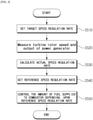
- FIG. 4 illustrates a method of controlling to set the reference speed regulation rate and to match the target speed regulation rate in the control device 100 in accordance with one embodiment of the present invention.
- the control device 100 in accordance with one embodiment of the present invention may firstly set the target speed regulation rate for the gas turbine system in order for the gas turbine system to operate to meet the target speed regulation rate (S510). Then, the rotor speed of the turbine 20 and the output of the power generator 50 may be measured (S520). At this time, with the gas turbine system operating to meet the target speed regulation rate, the system frequency can be determined based on the rotor speed the turbine 20. If the system frequency is the rated frequency, the control by the speed regulation rate is not required, in which case the output of the power generator 50 at the rated frequency can be measured and stored.
- the control device 100 can set the reference speed regulation rate ( ⁇ ref ) that is referenced in order for the fuel amount control unit 130 to control the amount of fuel.
- the initial reference speed regulation rate ( ⁇ ref ) may be set to be identical to the target speed regulation rate ( ⁇ t ), and the actual speed regulation rate ( ⁇ r ) may be calculated based on the rotor speed of the turbine 20 and the output of the power generator 50 accumulated and measured during a predetermined time period (S530).
- a new reference speed regulation rate ( ⁇ ref ) can be set (S540), and the fuel amount control unit 130 can control the amount of fuel supplied to the combustor depending on the reference speed regulation rate ( ⁇ ref ) that is newly set (S550).
- the speed regulation rate setting unit 120 of the control device 100 can repetitively perform the steps S520 to S540, periodically, until the target speed regulation rate ( ⁇ t ) is satisfied.
- the speed regulation rate setting unit 120 can periodically set the reference speed regulation rate ( ⁇ ref ), so that the gas turbine system can be controlled to regulate the target speed regulation rate ( ⁇ t ).
- the output of the power generator 50 is obtained using Equation 3, and the new reference speed regulation rate is set so that the difference between the relative outputs of the power generator 50, as obtained by the new reference speed regulation rate and by the previous reference speed regulation rate, matches the difference obtained by the target rate and the actual rate.
- control device proposed in the present invention can provide the effect that the reference speed regulation rate can be set based on the actual speed regulation rate and the amount of fuel can be adjusted based on the reference speed regulation rate, thus achieving the target speed regulation rate in the gas turbine system.
Landscapes
- Engineering & Computer Science (AREA)
- Chemical & Material Sciences (AREA)
- Combustion & Propulsion (AREA)
- Mechanical Engineering (AREA)
- General Engineering & Computer Science (AREA)
- Power Engineering (AREA)
- Control Of Turbines (AREA)
- Control Of Eletrric Generators (AREA)
Claims (8)
- Gasturbinensteuervorrichtung (100) für ein Gasturbinensystem, das eine Brennkammervorrichtung (30) zum Erzeugen von Verbrennungsgas; eine Turbine (20), die einen Rotor aufweist, der durch das Verbrennungsgas gedreht werden soll; und einen Leistungsgenerator (50), der durch die Drehung des Rotors angetrieben werden soll, umfasst, wobei die Vorrichtung (100) Folgendes umfasst:eine Erfassungseinheit (110) zum Messen der Rotordrehzahl und einer Ausgabe des Leistungsgenerators (50);eine Einheit (120) zur Einstellung der Drehzahlregulierungsrate zum Berechnen einer tatsächlichen Drehzahlregulierungsrate (δr) basierend auf der gemessenen Rotordrehzahl und der gemessenen Ausgabe des Leistungsgenerators (50), und zum Einstellen einer Referenzdrehzahlregulierungsrate (δref) basierend auf der tatsächlichen Drehzahlregulierungsrate und einer Solldrehzahlregulierungsrate (δt); undeine Brennstoffmengen-Steuerungseinheit (130) zum Steuern einer Menge von Brennstoff, die der Brennkammervorrichtung (30) zugeführt wird, basierend auf der eingestellten Referenzdrehzahlregulierungsrate;wobei die Brennstoffmengen-Steuerungseinheit (130) konfiguriert ist, die Menge von Brennstoff, die der Brennkammervorrichtung (30) zugeführt wird, durch das Bestimmen einer Ausgabe, die in dem Leistungsgenerator (50) erzeugt werden soll, basierend auf der gemessenen Rotordrehzahl und der eingestellten Referenzdrehzahlregulierungsrate zu steuern; undwobei die Einheit (120) zur Einstellung der Drehzahlregulierungsrate konfiguriert ist, die Referenzdrehzahlregulierungsrate derart einzustellen, dass die Differenz zwischen der Ausgabe des Leistungsgenerators (50), die durch die Referenzdrehzahlregulierungsrate (δref) erhalten wird, und der Ausgabe des Leistungsgenerators (50), die durch die Referenzdrehzahlregulierungsrate (δref) während einer vorherigen Periode erhalten worden ist, mit der Differenz zwischen der Ausgabe des Leistungsgenerators (50), die durch die Solldrehzahlregulierungsrate (δt) erhalten wird, und der Ausgabe des Leistungsgenerators (50), die durch die tatsächliche Drehzahlregulierungsrate (δr) erhalten wird, übereinstimmt; undwobei die Brennstoffmengen-Steuerungseinheit (130) konfiguriert ist, die Ausgabe, die in dem Leistungsgenerator (50) erzeugt werden soll, zu bestimmen, entsprechend:wobei NN eine Nennrotordrehzahl der Turbine (20) bezeichnet, N0 die Rotordrehzahl bei einer vorherigen Referenzdrehzahlregulierungsrate bezeichnet, NC eine aktuelle Rotordrehzahl bezeichnet, PN eine Nennleistung des Leistungsgenerators (50) bezeichnet, P0 die Leistungsgeneratorausgabe bei der vorherigen Referenzdrehzahlregulierungsrate bezeichnet, und δref die eingestellte Referenzdrehzahlregulierungsrate bezeichnet.

- Gasturbinensteuervorrichtung (100) nach dem vorhergehenden Anspruch, wobei die Erfassungseinheit (110) konfiguriert ist, die Rotordrehzahl und die Ausgabe des Leistungsgenerators (50) durch kumulatives Mitteln der während einer vorbestimmten Zeitdauer gemessenen Werte zu messen, und
wobei die Einheit (120) zur Einstellung der Drehzahlregulierungsrate konfiguriert ist, die Referenzdrehzahlregulierungsrate entsprechend der vorbestimmten Zeitdauer periodisch einzustellen. - Gasturbinensteuervorrichtung (100) nach Anspruch 2, wobei die Einheit (120) zur Einstellung der Drehzahlregulierungsrate konfiguriert ist, die tatsächliche Drehzahlregulierungsrate (δr) zu berechnen, entsprechend:

- Gasturbinensteuervorrichtung (100) nach einem der vorhergehenden Ansprüche, wobei die Einheit (120) zur Einstellung der Drehzahlregulierungsrate konfiguriert ist, die Ausgabe des Leistungsgenerators (50) zu berechnen, entsprechend:

- Gasturbinensteuervorrichtung (100) nach einem der vorhergehenden Ansprüche, wobei der Rotor eine Rotordrehzahl aufweist, die proportional zu einer Systemfrequenz ist, und eine Ausgabe des Leistungsgenerators (50) in Abhängigkeit von einer Solldrehzahlregulierungsrate eingestellt wird, um die Systemfrequenz auf eine Nennfrequenz wiederherzustellen.
- Gasturbinensystem, das Folgendes enthält:einen Kompressor (10) zum Ansaugen und Komprimieren von Außenluft;eine Brennkammervorrichtung (30) zum Verbrennen von Brennstoff und der Luft, die im Kompressor (10) komprimiert worden ist, um ein Verbrennungsgas zu erzeugen;eine Turbine (20), die einen Rotor aufweist, der durch das Verbrennungsgas gedreht werden soll;einen Leistungsgenerator (50), der durch die Drehung des Rotors angetrieben werden soll; undeine Gasturbinensteuervorrichtung (100) nach einem der vorhergehenden Ansprüche.
- Verfahren zum Steuern eines Gasturbinensystems, das eine Brennkammervorrichtung (30) zum Erzeugen von Verbrennungsgas; eine Turbine (20), die einen Rotor aufweist, der durch das Verbrennungsgas gedreht werden soll; und einen Leistungsgenerator (50), der durch die Rotation des Rotors angetrieben werden soll, umfasst, wobei das Verfahren Folgendes umfasst:Einstellen einer Solldrehzahlregulierungsrate (δt);Messen der Rotordrehzahl und der Ausgabe des Leistungsgenerators (50);Berechnen einer tatsächlichen Drehzahlregulierungsrate (δr) basierend auf der gemessenen Rotordrehzahl und der gemessenen Ausgabe des Leistungsgenerators (50);Einstellen einer Referenzdrehzahlregulierungsrate (δref) basierend auf der tatsächlichen Drehzahlregulierungsrate (δr) und der Solldrehzahlregulierungsrate; undSteuern einer Menge von Brennstoff, die der Brennkammervorrichtung (30) zugeführt werden soll, in Abhängigkeit von der eingestellten Referenzdrehzahlregulierungsrate, wobei die Menge von Brennstoff, die der Brennkammervorrichtung (30) zugeführt wird, durch das Bestimmen einer Ausgabe, die in dem Leistungsgenerator (50) erzeugt werden soll, basierend auf der gemessenen Rotordrehzahl und der eingestellten Referenzdrehzahlregulierungsrate, gesteuert wird; undwobei die Referenzdrehzahlregulierungsrate derart eingestellt ist, dass die Differenz zwischen der Ausgabe des Leistungsgenerators (50), die durch die Referenzdrehzahlregulierungsrate (δref) erhalten wird, und der Ausgabe des Leistungsgenerators (50), die durch die Referenzdrehzahlregulierungsrate (δref) während einer vorherigen Periode erhalten worden ist, mit der Differenz zwischen der Ausgabe des Leistungsgenerators (50), die durch die Solldrehzahlregulierungsrate (δt) erhalten wird, und der Ausgabe des Leistungsgenerators (50), die durch die tatsächliche Drehzahlregulierungsrate (δr) erhalten wird, übereinstimmt; undwobei die Ausgabe, die in dem Leistungsgenerator (50) erzeugt werden soll, bestimmt wird, entsprechend:wobei NN eine Nennrotordrehzahl der Turbine (20) bezeichnet, N0 die Rotordrehzahl bei einer vorherigen Referenzdrehzahlregulierungsrate bezeichnet, NC eine aktuelle Rotordrehzahl bezeichnet, PN eine Nennleistung des Leistungsgenerators (50) bezeichnet, P0 die Leistungsgeneratorausgabe bei der vorherigen Referenzdrehzahlregulierungsrate bezeichnet und δref die eingestellte Referenzdrehzahlregulierungsrate bezeichnet.

- Verfahren zum Steuern eines Gasturbinensystems nach Anspruch 7, wobei das Messen kumulatives Mitteln der während einer vorbestimmten Zeitdauer gemessenen Werte umfasst, und
wobei das Einstellen der Referenzdrehzahlregulierungsrate entsprechend der vorbestimmten Zeitdauer periodisch wiederholt wird.
Applications Claiming Priority (1)
| Application Number | Priority Date | Filing Date | Title |
|---|---|---|---|
| KR1020170053795A KR101893689B1 (ko) | 2017-04-26 | 2017-04-26 | 가스터빈 시스템 및 제어 방법 |
Publications (2)
| Publication Number | Publication Date |
|---|---|
| EP3396137A1 EP3396137A1 (de) | 2018-10-31 |
| EP3396137B1 true EP3396137B1 (de) | 2022-01-19 |
Family
ID=62148105
Family Applications (1)
| Application Number | Title | Priority Date | Filing Date |
|---|---|---|---|
| EP18168890.4A Active EP3396137B1 (de) | 2017-04-26 | 2018-04-24 | Gasturbinensystem und verfahren zur steuerung davon |
Country Status (4)
| Country | Link |
|---|---|
| US (1) | US10432119B2 (de) |
| EP (1) | EP3396137B1 (de) |
| JP (1) | JP6582331B2 (de) |
| KR (1) | KR101893689B1 (de) |
Families Citing this family (6)
| Publication number | Priority date | Publication date | Assignee | Title |
|---|---|---|---|---|
| KR101971337B1 (ko) * | 2017-04-24 | 2019-04-22 | 두산중공업 주식회사 | 가스터빈 시스템 및 제어 방법 |
| US11349264B2 (en) * | 2019-08-05 | 2022-05-31 | Raytheon Technologies Corporation | Capacitor-based connector for coaxial cable |
| GB202009197D0 (en) * | 2020-06-17 | 2020-07-29 | Rolls Royce Plc | Computer-implemented method |
| IT202100004130A1 (it) * | 2021-02-23 | 2022-08-23 | Nuovo Pignone Tecnologie Srl | System and method of operating an industrial gas turbine for supplying synthetic inertia to an electrical power grid |
| CN113803121B (zh) * | 2021-10-29 | 2023-12-22 | 国能龙源蓝天节能技术有限公司 | 低压汽轮机的自动控制方法及系统、发电系统 |
| KR102846617B1 (ko) | 2023-08-09 | 2025-08-14 | 한국전력공사 | 주파수 제어 성능 제고를 위한 발전기 제어 시스템 및 방법 |
Family Cites Families (44)
| Publication number | Priority date | Publication date | Assignee | Title |
|---|---|---|---|---|
| US3357177A (en) * | 1966-06-02 | 1967-12-12 | Gen Electric | Gas turbine engine fuel control system |
| US3488948A (en) * | 1968-04-29 | 1970-01-13 | Gen Electric | Gas turbine engine transient fuel control |
| US4208591A (en) * | 1973-06-20 | 1980-06-17 | Westinghouse Electric Corp. | Gas turbine power plant control apparatus including a turbine load control system |
| US4051669A (en) * | 1973-06-20 | 1977-10-04 | Westinghouse Electric Corporation | Gas turbine power plant control apparatus having a multiple backup control system |
| US3924141A (en) * | 1973-06-20 | 1975-12-02 | Westinghouse Electric Corp | Gas turbine power plant control apparatus including a two-shot shutdown system |
| US4019315A (en) * | 1973-06-20 | 1977-04-26 | Westinghouse Electric Corporation | Gas turbine power plant control apparatus including a temperature reset starting control system and an ignition pressure control system |
| US3892975A (en) * | 1973-06-20 | 1975-07-01 | Westinghouse Electric Corp | Gas turbine power plant control apparatus having improved monitoring and alarm elements |
| US3911285A (en) * | 1973-06-20 | 1975-10-07 | Westinghouse Electric Corp | Gas turbine power plant control apparatus having a multiple backup control system |
| US3943373A (en) * | 1973-06-20 | 1976-03-09 | Westinghouse Electric Corporation | Gas turbine power plant control apparatus including a speed/load hold and lock system |
| US4445180A (en) * | 1973-11-06 | 1984-04-24 | Westinghouse Electric Corp. | Plant unit master control for fossil fired boiler implemented with a digital computer |
| US4204401A (en) * | 1976-07-19 | 1980-05-27 | The Hydragon Corporation | Turbine engine with exhaust gas recirculation |
| US4271664A (en) * | 1977-07-21 | 1981-06-09 | Hydragon Corporation | Turbine engine with exhaust gas recirculation |
| US4314441A (en) * | 1977-07-22 | 1982-02-09 | Westinghouse Electric Corp. | Gas turbine power plant control apparatus including an ambient temperature responsive control system |
| US4242592A (en) * | 1977-10-11 | 1980-12-30 | Westinghouse Electric Corp. | Gas turbine power plant control apparatus including an ambient temperature responsive control system |
| US4188781A (en) * | 1978-04-25 | 1980-02-19 | General Electric Company | Non-linear dual mode regulator circuit |
| JPS6030404A (ja) * | 1983-07-28 | 1985-02-16 | Toshiba Corp | 複合サイクル・プラントの制御装置 |
| US5465570A (en) * | 1993-12-22 | 1995-11-14 | United Technologies Corporation | Fuel control system for a staged combustor |
| DE69720950T2 (de) | 1997-02-07 | 2004-03-11 | Alstom (Switzerland) Ltd. | Verfahren zur Steuerung einer Kraftwerksanlage |
| JP3002190B1 (ja) * | 1998-12-10 | 2000-01-24 | 川崎重工業株式会社 | タービン発電方法及び装置 |
| JP3887777B2 (ja) * | 2001-12-10 | 2007-02-28 | 株式会社日立製作所 | ガスタービン発電設備のガバナフリー制御方法及び制御装置 |
| US7143584B2 (en) * | 2002-02-15 | 2006-12-05 | Ebara Corporation | Gas turbine apparatus |
| JP2006207417A (ja) * | 2005-01-26 | 2006-08-10 | Denso Corp | 過給機付エンジン制御システム |
| US7805207B2 (en) * | 2008-03-28 | 2010-09-28 | Mitsubishi Electric Research Laboratories, Inc. | Method and apparatus for adaptive parallel proportional-integral-derivative controller |
| US8126629B2 (en) * | 2008-04-25 | 2012-02-28 | General Electric Company | Method and system for operating gas turbine engine systems |
| US8474271B2 (en) * | 2011-08-08 | 2013-07-02 | General Electric Company | System and method for hot ambient and grid frequency compensation for a gas turbine |
| US9334753B2 (en) * | 2011-10-12 | 2016-05-10 | General Electric Company | Control system and methods for controlling the operation of power generation systems |
| US20130257054A1 (en) * | 2012-03-29 | 2013-10-03 | General Electric Company | Gas Turbine - Variable Frequency Transformer Power Systems and Methods |
| US8849542B2 (en) * | 2012-06-29 | 2014-09-30 | United Technologies Corporation | Real time linearization of a component-level gas turbine engine model for model-based control |
| US9243519B2 (en) * | 2012-09-06 | 2016-01-26 | General Electric Company | Systems and methods for accelerating droop response to frequency variation of an electrical grid in a combined cycle power plant |
| US20140150438A1 (en) * | 2012-11-30 | 2014-06-05 | General Electric Company | System and method for operating a gas turbine in a turndown mode |
| US9562479B2 (en) * | 2013-03-13 | 2017-02-07 | General Electric Company | Systems and methods of droop response control of turbines |
| US20150184549A1 (en) * | 2013-12-31 | 2015-07-02 | General Electric Company | Methods and systems for enhancing control of power plant generating units |
| US9957843B2 (en) * | 2013-12-31 | 2018-05-01 | General Electric Company | Methods and systems for enhancing control of power plant generating units |
| US9404426B2 (en) * | 2013-12-31 | 2016-08-02 | General Electric Company | Methods and systems for enhancing control of power plant generating units |
| US10669959B2 (en) * | 2014-09-02 | 2020-06-02 | Mitsubishi Hitachi Power Systems, Ltd. | Control device, system, control method, power control device, gas turbine, and power control method |
| US10094297B2 (en) * | 2014-09-09 | 2018-10-09 | Hitachi, Ltd. | Power generation system and power generation method |
| US20160147204A1 (en) * | 2014-11-26 | 2016-05-26 | General Electric Company | Methods and systems for enhancing control of power plant generating units |
| US9932850B2 (en) * | 2015-02-03 | 2018-04-03 | General Electric Company | Correction system and method for gas turbine proportional droop governor |
| US9960598B2 (en) * | 2015-03-03 | 2018-05-01 | General Electric Company | Methods and systems for enhancing control of power plant generating units |
| US9932907B2 (en) * | 2015-03-03 | 2018-04-03 | General Electric Company | Methods and systems for enhancing control of power plant generating units |
| US9926852B2 (en) * | 2015-03-03 | 2018-03-27 | General Electric Company | Methods and systems for enhancing control of power plant generating units |
| US10287988B2 (en) * | 2015-03-27 | 2019-05-14 | General Electric Company | Methods and systems for enhancing operation of power plant generating units and systems |
| US10534328B2 (en) * | 2016-06-21 | 2020-01-14 | General Electric Company | Methods and systems for enhancing control of power plant generating units |
| KR101971337B1 (ko) * | 2017-04-24 | 2019-04-22 | 두산중공업 주식회사 | 가스터빈 시스템 및 제어 방법 |
-
2017
- 2017-04-26 KR KR1020170053795A patent/KR101893689B1/ko active Active
-
2018
- 2018-03-13 JP JP2018044931A patent/JP6582331B2/ja active Active
- 2018-04-14 US US15/953,407 patent/US10432119B2/en active Active
- 2018-04-24 EP EP18168890.4A patent/EP3396137B1/de active Active
Also Published As
| Publication number | Publication date |
|---|---|
| JP2018184949A (ja) | 2018-11-22 |
| JP6582331B2 (ja) | 2019-10-02 |
| KR101893689B1 (ko) | 2018-08-30 |
| US10432119B2 (en) | 2019-10-01 |
| US20180316293A1 (en) | 2018-11-01 |
| EP3396137A1 (de) | 2018-10-31 |
Similar Documents
| Publication | Publication Date | Title |
|---|---|---|
| EP3396137B1 (de) | Gasturbinensystem und verfahren zur steuerung davon | |
| EP2378085B1 (de) | Automatisiertes System und Verfahren zur Primärfrequenzgang Überwachung 
in einen Turbogenerator. | |
| US10184406B2 (en) | Multi-shaft variable speed gas turbine apparatus and method of controlling the same | |
| JP6812107B2 (ja) | ガスタービン比例ドループ調速機のための補正システムおよび方法 | |
| CN107810324B (zh) | 用于生成风力涡轮机控制时间表的方法和系统 | |
| CN101994647A (zh) | 风力涡轮的控制方法、中央控制器及其系统 | |
| CN104704701A (zh) | 线路阻抗补偿系统 | |
| JP7802904B2 (ja) | グリッド周波数の過渡事象に対する迅速な負荷サポートのための方法およびシステム | |
| KR102836883B1 (ko) | 송전선로 상의 스위칭 이벤트 동안 과도적 부하에서 발전소의 작동 | |
| US7161257B2 (en) | Active anti-islanding system and method | |
| EP3249770B1 (de) | Systeme und verfahren zur einstellung von operationen einer gasturbine nach einem vorübergehenden ereignis | |
| EP3396136B1 (de) | Gasturbinensystem und steuerungsvorrichtung und verfahren dafür | |
| US9632011B2 (en) | System and method for testing a gas turbine | |
| RU2360137C1 (ru) | Система автоматического управления энергетической установкой | |
| EP3396117B1 (de) | Gasturbinensystem und steuerungsvorrichtung und -verfahren dafür |
Legal Events
| Date | Code | Title | Description |
|---|---|---|---|
| PUAI | Public reference made under article 153(3) epc to a published international application that has entered the european phase |
Free format text: ORIGINAL CODE: 0009012 |
|
| STAA | Information on the status of an ep patent application or granted ep patent |
Free format text: STATUS: REQUEST FOR EXAMINATION WAS MADE |
|
| 17P | Request for examination filed |
Effective date: 20180424 |
|
| AK | Designated contracting states |
Kind code of ref document: A1 Designated state(s): AL AT BE BG CH CY CZ DE DK EE ES FI FR GB GR HR HU IE IS IT LI LT LU LV MC MK MT NL NO PL PT RO RS SE SI SK SM TR |
|
| AX | Request for extension of the european patent |
Extension state: BA ME |
|
| RBV | Designated contracting states (corrected) |
Designated state(s): AL AT BE BG CH CY CZ DE DK EE ES FI FR GB GR HR HU IE IS IT LI LT LU LV MC MK MT NL NO PL PT RO RS SE SI SK SM TR |
|
| GRAP | Despatch of communication of intention to grant a patent |
Free format text: ORIGINAL CODE: EPIDOSNIGR1 |
|
| STAA | Information on the status of an ep patent application or granted ep patent |
Free format text: STATUS: GRANT OF PATENT IS INTENDED |
|
| INTG | Intention to grant announced |
Effective date: 20210810 |
|
| GRAS | Grant fee paid |
Free format text: ORIGINAL CODE: EPIDOSNIGR3 |
|
| GRAA | (expected) grant |
Free format text: ORIGINAL CODE: 0009210 |
|
| STAA | Information on the status of an ep patent application or granted ep patent |
Free format text: STATUS: THE PATENT HAS BEEN GRANTED |
|
| AK | Designated contracting states |
Kind code of ref document: B1 Designated state(s): AL AT BE BG CH CY CZ DE DK EE ES FI FR GB GR HR HU IE IS IT LI LT LU LV MC MK MT NL NO PL PT RO RS SE SI SK SM TR |
|
| REG | Reference to a national code |
Ref country code: GB Ref legal event code: FG4D |
|
| REG | Reference to a national code |
Ref country code: CH Ref legal event code: EP |
|
| REG | Reference to a national code |
Ref country code: DE Ref legal event code: R096 Ref document number: 602018029691 Country of ref document: DE |
|
| REG | Reference to a national code |
Ref country code: AT Ref legal event code: REF Ref document number: 1463921 Country of ref document: AT Kind code of ref document: T Effective date: 20220215 |
|
| REG | Reference to a national code |
Ref country code: IE Ref legal event code: FG4D |
|
| REG | Reference to a national code |
Ref country code: LT Ref legal event code: MG9D |
|
| REG | Reference to a national code |
Ref country code: NL Ref legal event code: MP Effective date: 20220119 |
|
| REG | Reference to a national code |
Ref country code: AT Ref legal event code: MK05 Ref document number: 1463921 Country of ref document: AT Kind code of ref document: T Effective date: 20220119 |
|
| PG25 | Lapsed in a contracting state [announced via postgrant information from national office to epo] |
Ref country code: NL Free format text: LAPSE BECAUSE OF FAILURE TO SUBMIT A TRANSLATION OF THE DESCRIPTION OR TO PAY THE FEE WITHIN THE PRESCRIBED TIME-LIMIT Effective date: 20220119 |
|
| PG25 | Lapsed in a contracting state [announced via postgrant information from national office to epo] |
Ref country code: SE Free format text: LAPSE BECAUSE OF FAILURE TO SUBMIT A TRANSLATION OF THE DESCRIPTION OR TO PAY THE FEE WITHIN THE PRESCRIBED TIME-LIMIT Effective date: 20220119 Ref country code: RS Free format text: LAPSE BECAUSE OF FAILURE TO SUBMIT A TRANSLATION OF THE DESCRIPTION OR TO PAY THE FEE WITHIN THE PRESCRIBED TIME-LIMIT Effective date: 20220119 Ref country code: PT Free format text: LAPSE BECAUSE OF FAILURE TO SUBMIT A TRANSLATION OF THE DESCRIPTION OR TO PAY THE FEE WITHIN THE PRESCRIBED TIME-LIMIT Effective date: 20220519 Ref country code: NO Free format text: LAPSE BECAUSE OF FAILURE TO SUBMIT A TRANSLATION OF THE DESCRIPTION OR TO PAY THE FEE WITHIN THE PRESCRIBED TIME-LIMIT Effective date: 20220419 Ref country code: LT Free format text: LAPSE BECAUSE OF FAILURE TO SUBMIT A TRANSLATION OF THE DESCRIPTION OR TO PAY THE FEE WITHIN THE PRESCRIBED TIME-LIMIT Effective date: 20220119 Ref country code: HR Free format text: LAPSE BECAUSE OF FAILURE TO SUBMIT A TRANSLATION OF THE DESCRIPTION OR TO PAY THE FEE WITHIN THE PRESCRIBED TIME-LIMIT Effective date: 20220119 Ref country code: ES Free format text: LAPSE BECAUSE OF FAILURE TO SUBMIT A TRANSLATION OF THE DESCRIPTION OR TO PAY THE FEE WITHIN THE PRESCRIBED TIME-LIMIT Effective date: 20220119 Ref country code: BG Free format text: LAPSE BECAUSE OF FAILURE TO SUBMIT A TRANSLATION OF THE DESCRIPTION OR TO PAY THE FEE WITHIN THE PRESCRIBED TIME-LIMIT Effective date: 20220419 |
|
| PG25 | Lapsed in a contracting state [announced via postgrant information from national office to epo] |
Ref country code: PL Free format text: LAPSE BECAUSE OF FAILURE TO SUBMIT A TRANSLATION OF THE DESCRIPTION OR TO PAY THE FEE WITHIN THE PRESCRIBED TIME-LIMIT Effective date: 20220119 Ref country code: LV Free format text: LAPSE BECAUSE OF FAILURE TO SUBMIT A TRANSLATION OF THE DESCRIPTION OR TO PAY THE FEE WITHIN THE PRESCRIBED TIME-LIMIT Effective date: 20220119 Ref country code: GR Free format text: LAPSE BECAUSE OF FAILURE TO SUBMIT A TRANSLATION OF THE DESCRIPTION OR TO PAY THE FEE WITHIN THE PRESCRIBED TIME-LIMIT Effective date: 20220420 Ref country code: FI Free format text: LAPSE BECAUSE OF FAILURE TO SUBMIT A TRANSLATION OF THE DESCRIPTION OR TO PAY THE FEE WITHIN THE PRESCRIBED TIME-LIMIT Effective date: 20220119 Ref country code: AT Free format text: LAPSE BECAUSE OF FAILURE TO SUBMIT A TRANSLATION OF THE DESCRIPTION OR TO PAY THE FEE WITHIN THE PRESCRIBED TIME-LIMIT Effective date: 20220119 |
|
| PG25 | Lapsed in a contracting state [announced via postgrant information from national office to epo] |
Ref country code: IS Free format text: LAPSE BECAUSE OF FAILURE TO SUBMIT A TRANSLATION OF THE DESCRIPTION OR TO PAY THE FEE WITHIN THE PRESCRIBED TIME-LIMIT Effective date: 20220519 |
|
| REG | Reference to a national code |
Ref country code: DE Ref legal event code: R097 Ref document number: 602018029691 Country of ref document: DE |
|
| PG25 | Lapsed in a contracting state [announced via postgrant information from national office to epo] |
Ref country code: SM Free format text: LAPSE BECAUSE OF FAILURE TO SUBMIT A TRANSLATION OF THE DESCRIPTION OR TO PAY THE FEE WITHIN THE PRESCRIBED TIME-LIMIT Effective date: 20220119 Ref country code: SK Free format text: LAPSE BECAUSE OF FAILURE TO SUBMIT A TRANSLATION OF THE DESCRIPTION OR TO PAY THE FEE WITHIN THE PRESCRIBED TIME-LIMIT Effective date: 20220119 Ref country code: RO Free format text: LAPSE BECAUSE OF FAILURE TO SUBMIT A TRANSLATION OF THE DESCRIPTION OR TO PAY THE FEE WITHIN THE PRESCRIBED TIME-LIMIT Effective date: 20220119 Ref country code: EE Free format text: LAPSE BECAUSE OF FAILURE TO SUBMIT A TRANSLATION OF THE DESCRIPTION OR TO PAY THE FEE WITHIN THE PRESCRIBED TIME-LIMIT Effective date: 20220119 Ref country code: DK Free format text: LAPSE BECAUSE OF FAILURE TO SUBMIT A TRANSLATION OF THE DESCRIPTION OR TO PAY THE FEE WITHIN THE PRESCRIBED TIME-LIMIT Effective date: 20220119 Ref country code: CZ Free format text: LAPSE BECAUSE OF FAILURE TO SUBMIT A TRANSLATION OF THE DESCRIPTION OR TO PAY THE FEE WITHIN THE PRESCRIBED TIME-LIMIT Effective date: 20220119 |
|
| PLBE | No opposition filed within time limit |
Free format text: ORIGINAL CODE: 0009261 |
|
| STAA | Information on the status of an ep patent application or granted ep patent |
Free format text: STATUS: NO OPPOSITION FILED WITHIN TIME LIMIT |
|
| PG25 | Lapsed in a contracting state [announced via postgrant information from national office to epo] |
Ref country code: AL Free format text: LAPSE BECAUSE OF FAILURE TO SUBMIT A TRANSLATION OF THE DESCRIPTION OR TO PAY THE FEE WITHIN THE PRESCRIBED TIME-LIMIT Effective date: 20220119 |
|
| REG | Reference to a national code |
Ref country code: CH Ref legal event code: PL |
|
| 26N | No opposition filed |
Effective date: 20221020 |
|
| GBPC | Gb: european patent ceased through non-payment of renewal fee |
Effective date: 20220424 |
|
| REG | Reference to a national code |
Ref country code: BE Ref legal event code: MM Effective date: 20220430 |
|
| PG25 | Lapsed in a contracting state [announced via postgrant information from national office to epo] |
Ref country code: MC Free format text: LAPSE BECAUSE OF FAILURE TO SUBMIT A TRANSLATION OF THE DESCRIPTION OR TO PAY THE FEE WITHIN THE PRESCRIBED TIME-LIMIT Effective date: 20220119 Ref country code: LU Free format text: LAPSE BECAUSE OF NON-PAYMENT OF DUE FEES Effective date: 20220424 Ref country code: LI Free format text: LAPSE BECAUSE OF NON-PAYMENT OF DUE FEES Effective date: 20220430 Ref country code: GB Free format text: LAPSE BECAUSE OF NON-PAYMENT OF DUE FEES Effective date: 20220424 Ref country code: FR Free format text: LAPSE BECAUSE OF NON-PAYMENT OF DUE FEES Effective date: 20220430 Ref country code: CH Free format text: LAPSE BECAUSE OF NON-PAYMENT OF DUE FEES Effective date: 20220430 |
|
| PG25 | Lapsed in a contracting state [announced via postgrant information from national office to epo] |
Ref country code: SI Free format text: LAPSE BECAUSE OF FAILURE TO SUBMIT A TRANSLATION OF THE DESCRIPTION OR TO PAY THE FEE WITHIN THE PRESCRIBED TIME-LIMIT Effective date: 20220119 Ref country code: BE Free format text: LAPSE BECAUSE OF NON-PAYMENT OF DUE FEES Effective date: 20220430 |
|
| PG25 | Lapsed in a contracting state [announced via postgrant information from national office to epo] |
Ref country code: IE Free format text: LAPSE BECAUSE OF NON-PAYMENT OF DUE FEES Effective date: 20220424 |
|
| PG25 | Lapsed in a contracting state [announced via postgrant information from national office to epo] |
Ref country code: IT Free format text: LAPSE BECAUSE OF FAILURE TO SUBMIT A TRANSLATION OF THE DESCRIPTION OR TO PAY THE FEE WITHIN THE PRESCRIBED TIME-LIMIT Effective date: 20220119 |
|
| PG25 | Lapsed in a contracting state [announced via postgrant information from national office to epo] |
Ref country code: HU Free format text: LAPSE BECAUSE OF FAILURE TO SUBMIT A TRANSLATION OF THE DESCRIPTION OR TO PAY THE FEE WITHIN THE PRESCRIBED TIME-LIMIT; INVALID AB INITIO Effective date: 20180424 |
|
| PG25 | Lapsed in a contracting state [announced via postgrant information from national office to epo] |
Ref country code: MK Free format text: LAPSE BECAUSE OF FAILURE TO SUBMIT A TRANSLATION OF THE DESCRIPTION OR TO PAY THE FEE WITHIN THE PRESCRIBED TIME-LIMIT Effective date: 20220119 Ref country code: CY Free format text: LAPSE BECAUSE OF FAILURE TO SUBMIT A TRANSLATION OF THE DESCRIPTION OR TO PAY THE FEE WITHIN THE PRESCRIBED TIME-LIMIT Effective date: 20220119 |
|
| PG25 | Lapsed in a contracting state [announced via postgrant information from national office to epo] |
Ref country code: TR Free format text: LAPSE BECAUSE OF FAILURE TO SUBMIT A TRANSLATION OF THE DESCRIPTION OR TO PAY THE FEE WITHIN THE PRESCRIBED TIME-LIMIT Effective date: 20220119 |
|
| PG25 | Lapsed in a contracting state [announced via postgrant information from national office to epo] |
Ref country code: MT Free format text: LAPSE BECAUSE OF FAILURE TO SUBMIT A TRANSLATION OF THE DESCRIPTION OR TO PAY THE FEE WITHIN THE PRESCRIBED TIME-LIMIT Effective date: 20220119 |
|
| PGFP | Annual fee paid to national office [announced via postgrant information from national office to epo] |
Ref country code: DE Payment date: 20250225 Year of fee payment: 8 |