EP3396148B1 - Assemblage moteur dans un compartiment - Google Patents
Assemblage moteur dans un compartiment Download PDFInfo
- Publication number
- EP3396148B1 EP3396148B1 EP18169110.6A EP18169110A EP3396148B1 EP 3396148 B1 EP3396148 B1 EP 3396148B1 EP 18169110 A EP18169110 A EP 18169110A EP 3396148 B1 EP3396148 B1 EP 3396148B1
- Authority
- EP
- European Patent Office
- Prior art keywords
- engine compartment
- engine
- internal combustion
- air
- inlet
- Prior art date
- Legal status (The legal status is an assumption and is not a legal conclusion. Google has not performed a legal analysis and makes no representation as to the accuracy of the status listed.)
- Active
Links
Images



Classifications
-
- F—MECHANICAL ENGINEERING; LIGHTING; HEATING; WEAPONS; BLASTING
- F02—COMBUSTION ENGINES; HOT-GAS OR COMBUSTION-PRODUCT ENGINE PLANTS
- F02M—SUPPLYING COMBUSTION ENGINES IN GENERAL WITH COMBUSTIBLE MIXTURES OR CONSTITUENTS THEREOF
- F02M35/00—Combustion-air cleaners, air intakes, intake silencers, or induction systems specially adapted for, or arranged on, internal-combustion engines
- F02M35/10—Air intakes; Induction systems
- F02M35/10242—Devices or means connected to or integrated into air intakes; Air intakes combined with other engine or vehicle parts
- F02M35/10268—Heating, cooling or thermal insulating means
-
- B—PERFORMING OPERATIONS; TRANSPORTING
- B64—AIRCRAFT; AVIATION; COSMONAUTICS
- B64D—EQUIPMENT FOR FITTING IN OR TO AIRCRAFT; FLIGHT SUITS; PARACHUTES; ARRANGEMENT OR MOUNTING OF POWER PLANTS OR PROPULSION TRANSMISSIONS IN AIRCRAFT
- B64D33/00—Arrangement in aircraft of power plant parts or auxiliaries not otherwise provided for
- B64D33/02—Arrangement in aircraft of power plant parts or auxiliaries not otherwise provided for of combustion air intakes
-
- B—PERFORMING OPERATIONS; TRANSPORTING
- B64—AIRCRAFT; AVIATION; COSMONAUTICS
- B64D—EQUIPMENT FOR FITTING IN OR TO AIRCRAFT; FLIGHT SUITS; PARACHUTES; ARRANGEMENT OR MOUNTING OF POWER PLANTS OR PROPULSION TRANSMISSIONS IN AIRCRAFT
- B64D33/00—Arrangement in aircraft of power plant parts or auxiliaries not otherwise provided for
- B64D33/08—Arrangement in aircraft of power plant parts or auxiliaries not otherwise provided for of power plant cooling systems
- B64D33/10—Radiator arrangement
-
- F—MECHANICAL ENGINEERING; LIGHTING; HEATING; WEAPONS; BLASTING
- F01—MACHINES OR ENGINES IN GENERAL; ENGINE PLANTS IN GENERAL; STEAM ENGINES
- F01C—ROTARY-PISTON OR OSCILLATING-PISTON MACHINES OR ENGINES
- F01C1/00—Rotary-piston machines or engines
-
- F—MECHANICAL ENGINEERING; LIGHTING; HEATING; WEAPONS; BLASTING
- F01—MACHINES OR ENGINES IN GENERAL; ENGINE PLANTS IN GENERAL; STEAM ENGINES
- F01P—COOLING OF MACHINES OR ENGINES IN GENERAL; COOLING OF INTERNAL-COMBUSTION ENGINES
- F01P3/00—Liquid cooling
- F01P3/20—Cooling circuits not specific to a single part of engine or machine
-
- F—MECHANICAL ENGINEERING; LIGHTING; HEATING; WEAPONS; BLASTING
- F02—COMBUSTION ENGINES; HOT-GAS OR COMBUSTION-PRODUCT ENGINE PLANTS
- F02B—INTERNAL-COMBUSTION PISTON ENGINES; COMBUSTION ENGINES IN GENERAL
- F02B37/00—Engines characterised by provision of pumps driven at least for part of the time by exhaust
- F02B37/04—Engines with exhaust drive and other drive of pumps, e.g. with exhaust-driven pump and mechanically-driven second pump
- F02B37/10—Engines with exhaust drive and other drive of pumps, e.g. with exhaust-driven pump and mechanically-driven second pump at least one pump being alternatively or simultaneously driven by exhaust and other drive, e.g. by pressurised fluid from a reservoir or an engine-driven pump
- F02B37/105—Engines with exhaust drive and other drive of pumps, e.g. with exhaust-driven pump and mechanically-driven second pump at least one pump being alternatively or simultaneously driven by exhaust and other drive, e.g. by pressurised fluid from a reservoir or an engine-driven pump exhaust drive and pump being both connected through gearing to engine-driven shaft
-
- F—MECHANICAL ENGINEERING; LIGHTING; HEATING; WEAPONS; BLASTING
- F02—COMBUSTION ENGINES; HOT-GAS OR COMBUSTION-PRODUCT ENGINE PLANTS
- F02B—INTERNAL-COMBUSTION PISTON ENGINES; COMBUSTION ENGINES IN GENERAL
- F02B37/00—Engines characterised by provision of pumps driven at least for part of the time by exhaust
- F02B37/12—Control of the pumps
- F02B37/16—Control of the pumps by bypassing charging air
-
- F—MECHANICAL ENGINEERING; LIGHTING; HEATING; WEAPONS; BLASTING
- F02—COMBUSTION ENGINES; HOT-GAS OR COMBUSTION-PRODUCT ENGINE PLANTS
- F02B—INTERNAL-COMBUSTION PISTON ENGINES; COMBUSTION ENGINES IN GENERAL
- F02B41/00—Engines characterised by special means for improving conversion of heat or pressure energy into mechanical power
- F02B41/02—Engines with prolonged expansion
- F02B41/10—Engines with prolonged expansion in exhaust turbines
-
- F—MECHANICAL ENGINEERING; LIGHTING; HEATING; WEAPONS; BLASTING
- F02—COMBUSTION ENGINES; HOT-GAS OR COMBUSTION-PRODUCT ENGINE PLANTS
- F02C—GAS-TURBINE PLANTS; AIR INTAKES FOR JET-PROPULSION PLANTS; CONTROLLING FUEL SUPPLY IN AIR-BREATHING JET-PROPULSION PLANTS
- F02C6/00—Plural gas-turbine plants; Combinations of gas-turbine plants with other apparatus; Adaptations of gas-turbine plants for special use
- F02C6/04—Gas-turbine plants providing heated or pressurised working fluid for other apparatus, e.g. without mechanical power output
- F02C6/10—Gas-turbine plants providing heated or pressurised working fluid for other apparatus, e.g. without mechanical power output supplying working fluid to a user, e.g. a chemical process, which returns working fluid to a turbine of the plant
- F02C6/12—Turbochargers, i.e. plants for augmenting mechanical power output of internal-combustion piston engines by increase of charge pressure
-
- F—MECHANICAL ENGINEERING; LIGHTING; HEATING; WEAPONS; BLASTING
- F02—COMBUSTION ENGINES; HOT-GAS OR COMBUSTION-PRODUCT ENGINE PLANTS
- F02C—GAS-TURBINE PLANTS; AIR INTAKES FOR JET-PROPULSION PLANTS; CONTROLLING FUEL SUPPLY IN AIR-BREATHING JET-PROPULSION PLANTS
- F02C7/00—Features, components parts, details or accessories, not provided for in, or of interest apart form groups F02C1/00 - F02C6/00; Air intakes for jet-propulsion plants
- F02C7/04—Air intakes for gas-turbine plants or jet-propulsion plants
- F02C7/057—Control or regulation
-
- F—MECHANICAL ENGINEERING; LIGHTING; HEATING; WEAPONS; BLASTING
- F02—COMBUSTION ENGINES; HOT-GAS OR COMBUSTION-PRODUCT ENGINE PLANTS
- F02C—GAS-TURBINE PLANTS; AIR INTAKES FOR JET-PROPULSION PLANTS; CONTROLLING FUEL SUPPLY IN AIR-BREATHING JET-PROPULSION PLANTS
- F02C7/00—Features, components parts, details or accessories, not provided for in, or of interest apart form groups F02C1/00 - F02C6/00; Air intakes for jet-propulsion plants
- F02C7/12—Cooling of plants
- F02C7/14—Cooling of plants of fluids in the plant, e.g. lubricant or fuel
-
- F—MECHANICAL ENGINEERING; LIGHTING; HEATING; WEAPONS; BLASTING
- F02—COMBUSTION ENGINES; HOT-GAS OR COMBUSTION-PRODUCT ENGINE PLANTS
- F02M—SUPPLYING COMBUSTION ENGINES IN GENERAL WITH COMBUSTIBLE MIXTURES OR CONSTITUENTS THEREOF
- F02M31/00—Apparatus for thermally treating combustion-air, fuel, or fuel-air mixture
- F02M31/02—Apparatus for thermally treating combustion-air, fuel, or fuel-air mixture for heating
- F02M31/04—Apparatus for thermally treating combustion-air, fuel, or fuel-air mixture for heating combustion-air or fuel-air mixture
- F02M31/042—Combustion air
-
- F—MECHANICAL ENGINEERING; LIGHTING; HEATING; WEAPONS; BLASTING
- F02—COMBUSTION ENGINES; HOT-GAS OR COMBUSTION-PRODUCT ENGINE PLANTS
- F02M—SUPPLYING COMBUSTION ENGINES IN GENERAL WITH COMBUSTIBLE MIXTURES OR CONSTITUENTS THEREOF
- F02M31/00—Apparatus for thermally treating combustion-air, fuel, or fuel-air mixture
- F02M31/02—Apparatus for thermally treating combustion-air, fuel, or fuel-air mixture for heating
- F02M31/04—Apparatus for thermally treating combustion-air, fuel, or fuel-air mixture for heating combustion-air or fuel-air mixture
- F02M31/10—Apparatus for thermally treating combustion-air, fuel, or fuel-air mixture for heating combustion-air or fuel-air mixture by hot liquids, e.g. lubricants or cooling water
-
- F—MECHANICAL ENGINEERING; LIGHTING; HEATING; WEAPONS; BLASTING
- F02—COMBUSTION ENGINES; HOT-GAS OR COMBUSTION-PRODUCT ENGINE PLANTS
- F02M—SUPPLYING COMBUSTION ENGINES IN GENERAL WITH COMBUSTIBLE MIXTURES OR CONSTITUENTS THEREOF
- F02M35/00—Combustion-air cleaners, air intakes, intake silencers, or induction systems specially adapted for, or arranged on, internal-combustion engines
- F02M35/02—Air cleaners
- F02M35/08—Air cleaners with means for removing dust, particles or liquids from cleaners; with means for indicating clogging; with by-pass means; Regeneration of cleaners
- F02M35/088—Water, snow or ice proofing; Separation or drainage of water, snow or ice
-
- F—MECHANICAL ENGINEERING; LIGHTING; HEATING; WEAPONS; BLASTING
- F02—COMBUSTION ENGINES; HOT-GAS OR COMBUSTION-PRODUCT ENGINE PLANTS
- F02M—SUPPLYING COMBUSTION ENGINES IN GENERAL WITH COMBUSTIBLE MIXTURES OR CONSTITUENTS THEREOF
- F02M35/00—Combustion-air cleaners, air intakes, intake silencers, or induction systems specially adapted for, or arranged on, internal-combustion engines
- F02M35/10—Air intakes; Induction systems
- F02M35/10006—Air intakes; Induction systems characterised by the position of elements of the air intake system in direction of the air intake flow, i.e. between ambient air inlet and supply to the combustion chamber
- F02M35/10013—Means upstream of the air filter; Connection to the ambient air
-
- F—MECHANICAL ENGINEERING; LIGHTING; HEATING; WEAPONS; BLASTING
- F02—COMBUSTION ENGINES; HOT-GAS OR COMBUSTION-PRODUCT ENGINE PLANTS
- F02M—SUPPLYING COMBUSTION ENGINES IN GENERAL WITH COMBUSTIBLE MIXTURES OR CONSTITUENTS THEREOF
- F02M35/00—Combustion-air cleaners, air intakes, intake silencers, or induction systems specially adapted for, or arranged on, internal-combustion engines
- F02M35/10—Air intakes; Induction systems
- F02M35/1015—Air intakes; Induction systems characterised by the engine type
- F02M35/10157—Supercharged engines
-
- F—MECHANICAL ENGINEERING; LIGHTING; HEATING; WEAPONS; BLASTING
- F02—COMBUSTION ENGINES; HOT-GAS OR COMBUSTION-PRODUCT ENGINE PLANTS
- F02M—SUPPLYING COMBUSTION ENGINES IN GENERAL WITH COMBUSTIBLE MIXTURES OR CONSTITUENTS THEREOF
- F02M35/00—Combustion-air cleaners, air intakes, intake silencers, or induction systems specially adapted for, or arranged on, internal-combustion engines
- F02M35/10—Air intakes; Induction systems
- F02M35/10242—Devices or means connected to or integrated into air intakes; Air intakes combined with other engine or vehicle parts
- F02M35/10255—Arrangements of valves; Multi-way valves
-
- B—PERFORMING OPERATIONS; TRANSPORTING
- B64—AIRCRAFT; AVIATION; COSMONAUTICS
- B64D—EQUIPMENT FOR FITTING IN OR TO AIRCRAFT; FLIGHT SUITS; PARACHUTES; ARRANGEMENT OR MOUNTING OF POWER PLANTS OR PROPULSION TRANSMISSIONS IN AIRCRAFT
- B64D33/00—Arrangement in aircraft of power plant parts or auxiliaries not otherwise provided for
- B64D33/02—Arrangement in aircraft of power plant parts or auxiliaries not otherwise provided for of combustion air intakes
- B64D2033/0266—Arrangement in aircraft of power plant parts or auxiliaries not otherwise provided for of combustion air intakes specially adapted for particular type of power plants
- B64D2033/028—Arrangement in aircraft of power plant parts or auxiliaries not otherwise provided for of combustion air intakes specially adapted for particular type of power plants for piston engines
-
- B—PERFORMING OPERATIONS; TRANSPORTING
- B64—AIRCRAFT; AVIATION; COSMONAUTICS
- B64D—EQUIPMENT FOR FITTING IN OR TO AIRCRAFT; FLIGHT SUITS; PARACHUTES; ARRANGEMENT OR MOUNTING OF POWER PLANTS OR PROPULSION TRANSMISSIONS IN AIRCRAFT
- B64D29/00—Power-plant nacelles, fairings or cowlings
- B64D29/02—Power-plant nacelles, fairings or cowlings associated with wings
-
- F—MECHANICAL ENGINEERING; LIGHTING; HEATING; WEAPONS; BLASTING
- F01—MACHINES OR ENGINES IN GENERAL; ENGINE PLANTS IN GENERAL; STEAM ENGINES
- F01P—COOLING OF MACHINES OR ENGINES IN GENERAL; COOLING OF INTERNAL-COMBUSTION ENGINES
- F01P1/00—Air cooling
- F01P2001/005—Cooling engine rooms
-
- F—MECHANICAL ENGINEERING; LIGHTING; HEATING; WEAPONS; BLASTING
- F01—MACHINES OR ENGINES IN GENERAL; ENGINE PLANTS IN GENERAL; STEAM ENGINES
- F01P—COOLING OF MACHINES OR ENGINES IN GENERAL; COOLING OF INTERNAL-COMBUSTION ENGINES
- F01P2060/00—Cooling circuits using auxiliaries
- F01P2060/02—Intercooler
-
- F—MECHANICAL ENGINEERING; LIGHTING; HEATING; WEAPONS; BLASTING
- F01—MACHINES OR ENGINES IN GENERAL; ENGINE PLANTS IN GENERAL; STEAM ENGINES
- F01P—COOLING OF MACHINES OR ENGINES IN GENERAL; COOLING OF INTERNAL-COMBUSTION ENGINES
- F01P2060/00—Cooling circuits using auxiliaries
- F01P2060/04—Lubricant cooler
-
- F—MECHANICAL ENGINEERING; LIGHTING; HEATING; WEAPONS; BLASTING
- F01—MACHINES OR ENGINES IN GENERAL; ENGINE PLANTS IN GENERAL; STEAM ENGINES
- F01P—COOLING OF MACHINES OR ENGINES IN GENERAL; COOLING OF INTERNAL-COMBUSTION ENGINES
- F01P3/00—Liquid cooling
- F01P3/18—Arrangements or mounting of liquid-to-air heat-exchangers
-
- F—MECHANICAL ENGINEERING; LIGHTING; HEATING; WEAPONS; BLASTING
- F01—MACHINES OR ENGINES IN GENERAL; ENGINE PLANTS IN GENERAL; STEAM ENGINES
- F01P—COOLING OF MACHINES OR ENGINES IN GENERAL; COOLING OF INTERNAL-COMBUSTION ENGINES
- F01P5/00—Pumping cooling-air or liquid coolants
- F01P5/02—Pumping cooling-air; Arrangements of cooling-air pumps, e.g. fans or blowers
-
- F—MECHANICAL ENGINEERING; LIGHTING; HEATING; WEAPONS; BLASTING
- F01—MACHINES OR ENGINES IN GENERAL; ENGINE PLANTS IN GENERAL; STEAM ENGINES
- F01P—COOLING OF MACHINES OR ENGINES IN GENERAL; COOLING OF INTERNAL-COMBUSTION ENGINES
- F01P7/00—Controlling of coolant flow
- F01P7/02—Controlling of coolant flow the coolant being cooling-air
- F01P7/04—Controlling of coolant flow the coolant being cooling-air by varying pump speed, e.g. by changing pump-drive gear ratio
-
- F—MECHANICAL ENGINEERING; LIGHTING; HEATING; WEAPONS; BLASTING
- F02—COMBUSTION ENGINES; HOT-GAS OR COMBUSTION-PRODUCT ENGINE PLANTS
- F02B—INTERNAL-COMBUSTION PISTON ENGINES; COMBUSTION ENGINES IN GENERAL
- F02B33/00—Engines characterised by provision of pumps for charging or scavenging
- F02B33/32—Engines with pumps other than of reciprocating-piston type
- F02B33/34—Engines with pumps other than of reciprocating-piston type with rotary pumps
- F02B33/40—Engines with pumps other than of reciprocating-piston type with rotary pumps of non-positive-displacement type
-
- F—MECHANICAL ENGINEERING; LIGHTING; HEATING; WEAPONS; BLASTING
- F02—COMBUSTION ENGINES; HOT-GAS OR COMBUSTION-PRODUCT ENGINE PLANTS
- F02B—INTERNAL-COMBUSTION PISTON ENGINES; COMBUSTION ENGINES IN GENERAL
- F02B57/00—Internal-combustion aspects of rotary engines in which the combusted gases displace one or more reciprocating pistons
-
- F—MECHANICAL ENGINEERING; LIGHTING; HEATING; WEAPONS; BLASTING
- F05—INDEXING SCHEMES RELATING TO ENGINES OR PUMPS IN VARIOUS SUBCLASSES OF CLASSES F01-F04
- F05D—INDEXING SCHEME FOR ASPECTS RELATING TO NON-POSITIVE-DISPLACEMENT MACHINES OR ENGINES, GAS-TURBINES OR JET-PROPULSION PLANTS
- F05D2260/00—Function
- F05D2260/20—Heat transfer, e.g. cooling
- F05D2260/213—Heat transfer, e.g. cooling by the provision of a heat exchanger within the cooling circuit
-
- Y—GENERAL TAGGING OF NEW TECHNOLOGICAL DEVELOPMENTS; GENERAL TAGGING OF CROSS-SECTIONAL TECHNOLOGIES SPANNING OVER SEVERAL SECTIONS OF THE IPC; TECHNICAL SUBJECTS COVERED BY FORMER USPC CROSS-REFERENCE ART COLLECTIONS [XRACs] AND DIGESTS
- Y02—TECHNOLOGIES OR APPLICATIONS FOR MITIGATION OR ADAPTATION AGAINST CLIMATE CHANGE
- Y02T—CLIMATE CHANGE MITIGATION TECHNOLOGIES RELATED TO TRANSPORTATION
- Y02T10/00—Road transport of goods or passengers
- Y02T10/10—Internal combustion engine [ICE] based vehicles
- Y02T10/12—Improving ICE efficiencies
-
- Y—GENERAL TAGGING OF NEW TECHNOLOGICAL DEVELOPMENTS; GENERAL TAGGING OF CROSS-SECTIONAL TECHNOLOGIES SPANNING OVER SEVERAL SECTIONS OF THE IPC; TECHNICAL SUBJECTS COVERED BY FORMER USPC CROSS-REFERENCE ART COLLECTIONS [XRACs] AND DIGESTS
- Y02—TECHNOLOGIES OR APPLICATIONS FOR MITIGATION OR ADAPTATION AGAINST CLIMATE CHANGE
- Y02T—CLIMATE CHANGE MITIGATION TECHNOLOGIES RELATED TO TRANSPORTATION
- Y02T50/00—Aeronautics or air transport
- Y02T50/60—Efficient propulsion technologies, e.g. for aircraft
Definitions
- the application relates generally to engine compartments comprising internal combustion engines and, more particularly, to systems and methods used to feed air to such engines.
- EP 3 059 419 A1 discloses a prior art engine assembly according to the preamble of claim 1.
- an engine compartment comprising an engine assembly as set forth in claim 1.
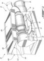
- an engine assembly 10 is generally shown and includes an internal combustion engine 12.
- the internal combustion engine 12 comprises one or more rotary engines, for example Wankel engines, or one or more reciprocating pistons.
- the internal combustion engine 12 drives a shaft 14 that is used for driving a rotatable load (not shown).
- the engine assembly 10 may alternately be configured to drive any other appropriate type of load, including, but not limited to, one or more generator(s), propeller(s), accessory(ies), rotor mast(s), compressor(s), or any other appropriate type of load or combination thereof.
- the engine assembly 10 a compound cycle engine system or compound cycle engine such as described in Lents et al.'s US patent No. 7,753,036 issued July 13, 2010 or as described in Julien et al.'s US patent No. 7,775,044 issued August 17, 2010 , or as described in Thomassin et al.'s U.S. patent publication No. 2015/0275749 published October 1, 2015 , or as described in Bolduc et al.'s U.S. patent publication No. 2015/0275756 published October 1, 2015 .
- the compound cycle engine system may be used as a prime mover engine, such as on an aircraft or other vehicle, or in any other suitable application.
- the engine assembly 10 is disposed inside an engine compartment 100.
- the engine compartment 100 is a nacelle, for fuselage or wing mounted engines, or a bay defined inside a vehicle (not shown) and adapted to receive the engine assembly 10.
- the engine compartment 100 has an inlet 102 and an outlet 104.
- the internal combustion engine 12 has an air intake 18 that may be selectively fluidly connected with a selected one of an interior 108 of the engine compartment 100 and an environment 110 outside thereof (e.g., to atmosphere).
- the inlet 102 and the outlet 104 of the engine compartment 100 are in fluid communication with the environment 110.
- the engine assembly 10 further comprises a heat exchanger 20 having one or more first conduit(s) 22 (one in the embodiment shown) fluidly connected to a fluid circuitry 23 of the internal combustion engine 12.
- the heat exchanger 20 further has one or more second conduit(s) 24 (one in the embodiment shown) fluidly connecting the interior 108 of the engine compartment 100 to the environment 110 through the inlet 102.
- the first conduit 22 is configured to receive hot fluids, for example liquid coolant or lubricant (e.g. oil), of the internal combustion engine 12 and/or the engine assembly 10; multiple conduits could be provided, for example to independently receive a liquid coolant and a lubricant.
- the heat exchanger 20 is configured to provide heat exchange relationship between the hot fluid(s) circulating in the first conduit 22 and an airflow F circulating in the second conduit 24.
- the heat exchanger 20 extends over the inlet 102 of the engine compartment 100 to define a portion of a wall 112 of the engine compartment 100.
- the engine assembly 10 further includes a forced air system 28 operable in use to provide an air flow from the environment 110 to the outlet 104 via the second conduit 24 of the heat exchanger and the engine compartment 100, i.e., the flow F circulates from the environment 110 through the inlet 102, through the second conduit 24 of the heat exchanger 20, into the engine compartment 100, and out through the outlet 104.
- the airflow F passing in the second conduit 24 of the heat exchanger 20 picks up heat from the hot fluid(s) circulating through the first conduit 22 while entering in the engine compartment 100 such that the air of the engine compartment interior 108 is warmer than outside air in the environment 110.
- the forced air system 28 is disposed adjacent the outlet 104 of the engine compartment 100; the forced air system 28 is operable to expel air from the interior 108 of the engine compartment toward the environment 110. By doing so, a pressure differential occurs between the interior 108 and the environment 110 which causes the outside air of the environment to be drawn in the engine compartment through the inlet 102 and hence through the heat exchanger 20.
- Other configurations, which are not part of the invention, are also possible.
- the internal combustion engine 12 may receive either outside air from the environment 110 or warmer inside air from the engine compartment 100.
- the engine assembly 10 further has a selector valve 30 configurable to selectively fluidly connect the air intake 18 of the internal combustion engine 12 with a first assembly inlet 74 communicating with the interior 108 of the engine compartment 100 in a first valve position, and with a second assembly inlet 76 in fluid communication with the environment 110 independently of the compartment 100 in a second valve position.
- the selector valve 30 also has an intermediate valve position where the valve fluidly connects the air intake 18 of the internal combustion engine 12 with both of the assembly inlets 74, 76 so the internal combustion engine 12 can receive a mix of air from the environment 110 and inside air from the engine compartment 100.
- a temperature of the air fed to the internal combustion engine 12 is variable in function of the operating conditions. For example, in a situation in which outside air is below a given threshold, the selector valve 30 allows to feed the internal combustion engine 12 with the air of the engine compartment 100 rather than, or in addition to, air from the environment 110. In warmer operating conditions, or in any occasion where cooler air is desirable, the air from the environment 110 may be fed to the internal combustion engine 10.
- the engine assembly 10 further includes a compressor 32 for compressing the air before it is fed to the air intake 18 of the internal combustion engine 12, and a turbine section 34 receiving the exhaust gases from the internal combustion engine 12. It is understood that variations are possible, and that, for example, the compressor 32 and/or turbine section 34 may be omitted.
- the internal combustion engine 12, the compressor 32, and the turbine section 34 are in driving engagement with a gearbox 36.
- the gear box 36 is configured to allow the turbine section 34 to compound power with the shaft 14 and to allow the turbine section 34 and/or the internal combustion engine 12 to drive the compressor 32.
- the compressor 32, the turbine section 34, and the gearbox 36 are serially disposed along a rotational axis R.
- a rotational axis R' of the internal combustion engine 12 is radially offset from the rotational axis R of the compressor 32 and of the turbine section 34.
- shafts 35, 37, and 39 are used to connect the compressor 32, the turbine section 34, and the internal combustion engine 12 to the gearbox 36, respectively.
- Alternate configurations are possible, including, but not limited to, the compressor 32, turbine section 34, and internal combustion engine 12 disposed coaxially, or two or more of the shafts 35, 37, 39 extending at an angle (perpendicularly or otherwise) to each other.
- the engine assembly 10 further comprises an intake plenum 60 having an outlet 62 ( Fig. 4 ) fluidly connected to an inlet 38 of the compressor 32, while an outlet 40 of the compressor 32 is in fluid communication with the air intake 18 of the internal combustion engine 12, for example through a conduit 42.
- the intake plenum 60 is in selective fluid communication with one or both of the assembly inlets 74, 76 through the selector valve 30, and is accordingly configured to receive air either from the interior 108 of the engine compartment 100 or from the environment 110, or from both. Therefore, the internal combustion engine 12 receives the pressurized air from the compressor 32, and the internal combustion engine 12 is in selective fluid communication with one or both of the assembly inlets 74, 76 through the compressor 32 and intake plenum 60.
- the internal combustion engine 12 provides an exhaust flow of high pressure hot gas exiting at high peak velocity.
- the exhaust flow is in the form of exhaust pulses.
- an exhaust 44 of the internal combustion engine 12 (corresponding to or communicating with an exhaust port of a respective rotary engine/reciprocating pistons of the internal combustion engine 12) is in fluid communication with an inlet 46 of the turbine section 34 via a conduit 48. Accordingly, the exhaust flow from the internal combustion engine 12 is supplied to the turbine section 34.
- the turbine section 34 comprises two turbine stages 34a and 34b in serial fluid communication. Other configurations are contemplated.
- the flow of exhaust gases exits an outlet 50 of the turbine section 34 and is expelled out of the engine compartment 100, for example to the environment 110.
- Figs. 2-4 illustrate an exemplary configuration for the engine 10 of Fig. 1 ; other configurations are contemplated.
- the walls 112 of the engine compartment 100 define the compartment inlet 102.
- the heat exchanger 20 covers the compartment inlet 102 such that at least a portion of a wall or an entirety of a wall of the engine compartment 100 is defined by the heat exchanger 20.
- the engine compartment 100 is defined by walls extending from and connected around a perimeter of the heat exchanger 20, with the inlet side of the heat exchanger 20 being directly exposed to the environment, and the opposed outlet side of the heat exchanger 20 being directly exposed to the interior 108 of the compartment 100.
- the heat exchanger 20 is thus partly inside the compartment 100 and partly exposed to the environment 110.
- the heat exchanger 20 comprises an oil cooler 20a and a liquid cooler 20b.
- the liquid cooler 20b is configured to cool a liquid coolant of the internal combustion engine 12.
- the engine assembly 10 further includes an air manifold 82 for distributing the air to the internal combustion engine 12.
- the air manifold 82 has an inlet fluidly connected to the compressor outlet 40 through the conduit 42.
- the air manifold 82 has an outlet fluidly connected with the air intake 18 of the internal combustion engine 12.
- the air manifold 82 incorporates an intercooler, so as to cool the compressed air between the compressor 32 and the internal combustion engine 12.
- Other configurations are also possible.
- the engine assembly includes an exhaust conduit 64 having an inlet 66 fluidly connected to the outlet 50 of the turbine section 34.
- An outlet of the exhaust conduit 64 opens to the environment 110 to expel the exhaust gases in the environment 110.
- the forced air system 28 includes a fan, which is disposed (in the embodiment shown) at an extremity of a conduit 70 fluidly connected with the engine compartment 100.
- the fan may be driven by a motor (not shown), for example an electric or hydraulic motor. Alternately, the fan may be driven by the internal combustion engine 12 and/or the turbine section 34.
- the fan may be a constant speed fan or a variable speed fan.
- the forced air system 28 draws air in the engine compartment 100 through the heat exchanger 20 and out of the engine compartment 100 through the outlet 104 ( Fig. 1 ).
- the exhaust from the turbine section 34 can be mixed with the cooling flow of the forced air system 28, for example in the conduit 70, either downstream or upstream of forced air system 28; in a particular embodiment where the forced air system 28 is a fan, the exhaust flow is mixed with the cooling flow downstream of the fan to avoid exposing the blades of the fan to the hot and dirty exhaust gases.
- the selector valve 30 is disposed in the intake plenum 60 and includes a door 72.
- the intake plenum 60 selectively communicates with the assembly inlet 74 in fluid communication with the interior 108 and the assembly inlet 76 in direct fluid communication with the environment 110, depending on the valve position as defined by the door 72.
- the door 72 is pivotable to selectively allow fluid communication between the intake plenum 60 and one or both of the assembly inlets 74, 76, for example to selectively allow fluid communication between the intake plenum 60 and one the assembly inlets 74, 76 while blocking fluid communication between the intake plenum 60 and the other one of the assembly inlets 74, 76.
- the outlet 62 of the intake plenum 60 is fluidly connected with the inlet 38 of the compressor 32.
- the internal combustion engine air intake 18 is fluidly connected with the intake plenum outlet 62 through the compressor 32.
- the intake plenum 60 includes an air filter 80 disposed therein.
- the air filter 80 is configured to remove impurity of the air before it is fed to the compressor 32 and internal combustion engine 12.
- the air filter 80 is positioned between the intake plenum outlet 62 and the assembly inlets 74, 76.
- the air filter 80 thus filters the air regardless of its origin (environment 110 and/or engine compartment 100).
- Other configurations are also possible; for example, a filter bypass could be provided so that the flow from the assembly inlets 74, 76 can circulate to the intake plenum outlet 62 without going through the filter 80, for use for example when the filter 80 is partially or completely blocked.
- the engine compartment 100 is heated by cooling a fluid circulating of the internal combustion engine 12.
- the fluid may be, for example, oil or a liquid coolant of the engine 12. It is therefore possible to feed the internal combustion engine 12 with a selected one of the outside air of the environment 110 and the air in the engine compartment 100 in function of the operating conditions by configuring the selector valve 30 in a selected one of the first and second valve positions.
- the heating of the outside air is carried through the heat exchanger 20 disposed adjacent the compartment inlet 102.
- the heat exchanger provides heat exchange relationship between the fluid of the internal combustion engine 12 and the outside air circulating through the heat exchanger 20.
- a position of a selector valve 30 is selected to allow fluid communication between the air intake 18 of the internal combustion engine 12 and the selected one of the environment 110 and the engine compartment 100.
- the selector valve 30 may also block fluid communication between the air intake 18 and the other one of the environment 110 and the engine compartment 100, or alternately allow fluid communication between the air intake 18 and both the environment 110 and engine compartment 100.
- the position of the selector valve 30 allows fluid communication between the intake plenum 60 and one of the assembly inlets 74, 76 while blocking fluid communication between the intake plenum 60 and the other one of assembly inlets 74, 76.
- the valve 30 can also be positioned so that simultaneous communication of the intake plenum 60 with both inlets 74, 76 is allowed, so that a mixed flow from both sources can be provided to feed the internal combustion engine 12.
- the air of the engine compartment 100 and/or the air of the environment 110 is compressed by the compressor 32 before being directed to the air intake 18 of the engine 12.
- the compressor 32 may be omitted.
- the position of the selector valve 30 varies in function of a temperature of the outside air. Accordingly, if the temperature of the outside air is below a threshold, the internal combustion engine 12 is fed with the air of the engine compartment 100.
- the threshold is about 32°F (0°C); other values are also possible.
- the position of the selector valve 30 varies in accordance with other parameters of the engine assembly 10; for example, so that the internal combustion engine 12 is fed at least in part with the air of the engine compartment 100 during cold start or relights at temperatures different than below 32°F (0°C).
- a controller (not shown) is used to control the position of the selector valve 30, based on the temperature of the outside air and other conditions related to icing probabilities, for example as determined by a suitable sensor, and/or based on other parameters of the engine assembly 10. Therefore, such a controller may comprise a temperature determining module and a selector valve controlling module. In the depicted embodiment, controlling the selector valve 30 comprises controlling movements of the pivotable door 72.
- the assembly 10 thus allows for a selection of a source of air for the engine 12 depending on operating conditions, while providing for a simple configuration taking advantage of "waste" heat generated by the heat exchanger 20 to selectively provide a source of heated air.
Landscapes
- Engineering & Computer Science (AREA)
- Chemical & Material Sciences (AREA)
- Combustion & Propulsion (AREA)
- Mechanical Engineering (AREA)
- General Engineering & Computer Science (AREA)
- Aviation & Aerospace Engineering (AREA)
- Chemical Kinetics & Catalysis (AREA)
- General Chemical & Material Sciences (AREA)
- Supercharger (AREA)
Claims (14)
- Compartiment moteur (100), comprenant :une entrée (102), le compartiment moteur (100) étant connecté fluidiquement à un environnement (110) à travers l'entrée (102) ;une sortie (104) ; etun assemblage moteur (10) disposé à l'intérieur du compartiment moteur (100), l'assemblage moteur (10) comprenant :un moteur à combustion interne (12) reçu à l'intérieur du compartiment moteur (100) ;un échangeur de chaleur (20) ayant un premier conduit (22) connecté fluidiquement à un circuit de fluide (23) du moteur à combustion interne (12) et un second conduit (24) connectant fluidiquement l'intérieur (108) du compartiment moteur (100) à un environnement (110) à l'extérieur du compartiment (100), le premier conduit (22) étant en relation d'échange de chaleur avec le second conduit (24) ;un système à air pulsé (28) comprenant un ventilateur pouvant fonctionner pour expulser l'air de l'intérieur (108) du compartiment moteur (100) vers l'environnement (110) de manière à fournir un écoulement d'air (F) de l'environnement (110) vers la sortie (104) par le biais du second conduit (24) de l'échangeur de chaleur (20) et le compartiment moteur (100) ;une soupape de sélection (30) configurable pour connecter sélectivement et fluidiquement une admission d'air (18) du moteur à combustion interne (12) à l'intérieur (108) du compartiment moteur (100) dans une première position de soupape et à l'environnement (110) dans une seconde position de soupape ; et un plénum d'admission (60) en communication fluidique avec l'admission d'air (18) du moteur à combustion interne (12) ;une première entrée d'assemblage (74) en communication fluidique avec l'intérieur (108) du compartiment moteur (100) ; etune seconde entrée d'assemblage (76) en communication fluidique directe avec l'environnement (110), la soupape de sélection (30) connectant sélectivement et fluidiquement le plénum d'admission (60) à la première entrée (74) dans la première position de soupape et à la seconde entrée (76) dans la seconde position de soupape.
- Compartiment moteur (100) selon la revendication 1, dans lequel l'échangeur de chaleur (20) définit une partie d'une paroi (112) du compartiment moteur (100).
- Compartiment moteur (100) selon la revendication 2, dans lequel l'échangeur de chaleur (20) s'étend sur l'entrée (102), et le second conduit (24) de l'échangeur de chaleur (20) est connecté fluidiquement à l'environnement (108) par le biais de l'entrée (102).
- Compartiment moteur (100) selon une quelconque revendication précédente, dans lequel la soupape de sélection (30) est également configurable pour connecter simultanément fluidiquement l'admission d'air (18) du moteur à combustion interne (12) à l'intérieur (108) du compartiment moteur (100) et à l'environnement (110).
- Compartiment moteur (100) selon une quelconque revendication précédente, dans lequel une partie de l'échangeur de chaleur (20) est à l'intérieur du compartiment moteur (100).
- Compartiment moteur (100) selon une quelconque revendication précédente, dans lequel le moteur à combustion interne (12) est un moteur rotatif.
- Compartiment moteur (100) selon une quelconque revendication précédente, comprenant également un compresseur (32) ayant une entrée (38) connectée sélectivement et fluidiquement à l'intérieur (108) du compartiment moteur (100) dans la première position de soupape et à l'environnement (110) dans la seconde position de soupape, et une sortie (40) connectée fluidiquement à l'admission d'air (18) du moteur à combustion interne (12).
- Compartiment moteur (100) selon une quelconque revendication précédente, comprenant également une turbine (34) ayant une entrée (46) connectée fluidiquement à un échappement (44) du moteur à combustion interne (12), la turbine (34) étant en prise d'entraînement avec le moteur à combustion interne (12).
- Procédé d'alimentation en air du moteur à combustion interne (12) du compartiment moteur (100) selon une quelconque revendication précédente, le procédé comprenant :l'aspiration d'air extérieur dans le compartiment moteur (100) à travers l'entrée (102), qui est définie dans les parois (112) du compartiment moteur (100) ;le chauffage de l'air extérieur tout en entrant dans le compartiment moteur (100) à travers l'entrée (102) de sorte que l'air dans le compartiment moteur (100) est plus chaud que l'air extérieur, l'air étant chauffé par refroidissement d'un fluide du moteur à combustion interne (12) ; etla configuration de la soupape de sélection (30) dans une position sélectionnée parmi les première et seconde positions de soupape pour alimenter en air le moteur à combustion interne (12), le moteur à combustion interne (12) étant alimenté par l'air présent dans le compartiment moteur (100) dans la première position de soupape et étant alimenté par l'air extérieur dans la seconde position de soupape.
- Procédé selon la revendication 9, dans lequel le chauffage de l'air extérieur comprend le chauffage de l'air extérieur à travers l'échangeur de chaleur (20) disposé à proximité de l'entrée (102) et la fourniture d'une relation d'échange de chaleur entre le fluide du moteur à combustion interne (12) et l'air extérieur circulant à travers l'échangeur de chaleur (20) .
- Procédé selon la revendication 9 ou 10, dans lequel la configuration de la soupape de sélection (30) dans la position sélectionnée parmi les première et seconde positions de soupape permet une communication fluidique entre l'admission d'air (18) du moteur à combustion interne (12) et l'un parmi l'environnement (110) autour du compartiment moteur (100) et l'intérieur (108) du compartiment moteur (100), et bloque la communication fluidique entre l'admission d'air (18) et l'autre parmi l'environnement (110) et l'intérieur (108) du compartiment moteur (100).
- Procédé selon l'une quelconque des revendications 9 à 11, dans lequel la configuration de la soupape de sélection (30) dans la position sélectionnée parmi les première et seconde positions de soupape comprend la permission d'une communication fluidique entre le plénum d'admission (60) et l'une ou les deux parmi la première entrée (74) et la seconde entrée (76), le plénum d'admission (60) ayant une sortie (62) connectée fluidiquement à l'admission d'air (18) du moteur à combustion interne (12), la première entrée (74) étant connectée fluidiquement à un intérieur (108) du compartiment moteur (100), la seconde entrée (76) étant connectée fluidiquement à un environnement (110) autour du compartiment moteur (100).
- Procédé selon l'une quelconque des revendications 9 à 12, comprenant également la compression de l'air avant d'alimenter en air le moteur à combustion interne (12).
- Procédé selon l'une quelconque des revendications 9 à 13, comprenant également la détermination du fait de savoir si une température de l'air extérieur est inférieure à un seuil, et la configuration de la soupape de sélection dans la première position de soupape (30) si la température est inférieure au seuil.
Applications Claiming Priority (1)
| Application Number | Priority Date | Filing Date | Title |
|---|---|---|---|
| US15/496,446 US10883457B2 (en) | 2017-04-25 | 2017-04-25 | Engine compartment heating assembly |
Publications (2)
| Publication Number | Publication Date |
|---|---|
| EP3396148A1 EP3396148A1 (fr) | 2018-10-31 |
| EP3396148B1 true EP3396148B1 (fr) | 2024-08-28 |
Family
ID=62063350
Family Applications (1)
| Application Number | Title | Priority Date | Filing Date |
|---|---|---|---|
| EP18169110.6A Active EP3396148B1 (fr) | 2017-04-25 | 2018-04-24 | Assemblage moteur dans un compartiment |
Country Status (3)
| Country | Link |
|---|---|
| US (1) | US10883457B2 (fr) |
| EP (1) | EP3396148B1 (fr) |
| CA (1) | CA2998152A1 (fr) |
Families Citing this family (3)
| Publication number | Priority date | Publication date | Assignee | Title |
|---|---|---|---|---|
| US10875660B1 (en) * | 2019-06-05 | 2020-12-29 | Pratt & Whitney Canada Corp. | Aircraft power plant |
| US10967983B2 (en) * | 2019-06-05 | 2021-04-06 | Pratt & Whitney Canada Corp. | Aircraft power plant |
| US12031473B2 (en) * | 2022-10-21 | 2024-07-09 | Pratt & Whitney Canada Corp. | Aircraft propulsion system with intermittent combustion engine, hydraulic motor, and cooling system |
Family Cites Families (11)
| Publication number | Priority date | Publication date | Assignee | Title |
|---|---|---|---|---|
| US4924826A (en) | 1989-04-27 | 1990-05-15 | Vinson Paul S | Temperature responsive engine compartment |
| EP1611331B1 (fr) | 2003-02-24 | 2010-09-01 | Pratt & Whitney Canada Corp. | Moteur rotatif turbo-combine integre a faible taux de compression volumetrique |
| US7753036B2 (en) | 2007-07-02 | 2010-07-13 | United Technologies Corporation | Compound cycle rotary engine |
| US20120180477A1 (en) | 2011-01-14 | 2012-07-19 | Gregory Alan Marsh | Thermal management systems and methods |
| US9926843B2 (en) | 2012-07-20 | 2018-03-27 | Pratt & Whitney Canada Corp. | Compound cycle engine |
| US10107195B2 (en) | 2012-07-20 | 2018-10-23 | Pratt & Whitney Canada Corp. | Compound cycle engine |
| US9303549B2 (en) | 2012-11-02 | 2016-04-05 | General Electric Company | Engine cooling system and method for an engine |
| US8978628B2 (en) | 2013-06-06 | 2015-03-17 | The Boeing Company | Engine cooling system |
| US9879591B2 (en) * | 2015-02-20 | 2018-01-30 | Pratt & Whitney Canada Corp. | Engine intake assembly with selector valve |
| US9896998B2 (en) | 2015-02-20 | 2018-02-20 | Pratt & Whitney Canada Corp. | Compound engine assembly with modulated flow |
| US10710738B2 (en) | 2015-06-25 | 2020-07-14 | Pratt & Whitney Canada Corp. | Auxiliary power unit with intercooler |
-
2017
- 2017-04-25 US US15/496,446 patent/US10883457B2/en active Active
-
2018
- 2018-03-14 CA CA2998152A patent/CA2998152A1/fr active Pending
- 2018-04-24 EP EP18169110.6A patent/EP3396148B1/fr active Active
Also Published As
| Publication number | Publication date |
|---|---|
| CA2998152A1 (fr) | 2018-10-25 |
| US10883457B2 (en) | 2021-01-05 |
| EP3396148A1 (fr) | 2018-10-31 |
| US20180306147A1 (en) | 2018-10-25 |
Similar Documents
| Publication | Publication Date | Title |
|---|---|---|
| EP3109166B1 (fr) | Ensemble moteur combiné avec de l'air de prélèvement | |
| EP3109161B1 (fr) | Ensemble moteur composé à entraînement direct de générateur | |
| EP3112271B1 (fr) | Unité de puissance auxiliaire à récupération de l'excès d'air | |
| EP3109167B1 (fr) | Unité de puissance auxiliaire avec refroidisseur intermédiaire | |
| CA2961115C (fr) | Systeme de commande directionnelle et methode de fourniture de commande directionnelle | |
| US11525388B2 (en) | Active control flow system and method of cooling and providing active flow control | |
| EP3059419B1 (fr) | Ensemble moteur composé à débit de radiateur modulé | |
| CA2921377C (fr) | Ensemble de moteur combine a conduit d'entree commun | |
| US11092122B2 (en) | Engine assembly with engine and cooler compartments | |
| EP3396148B1 (fr) | Assemblage moteur dans un compartiment | |
| US10823041B2 (en) | Engine assembly with plenum and remote fan | |
| RU232136U1 (ru) | Квадрокоптер с комбинированной силовой установкой |
Legal Events
| Date | Code | Title | Description |
|---|---|---|---|
| PUAI | Public reference made under article 153(3) epc to a published international application that has entered the european phase |
Free format text: ORIGINAL CODE: 0009012 |
|
| STAA | Information on the status of an ep patent application or granted ep patent |
Free format text: STATUS: THE APPLICATION HAS BEEN PUBLISHED |
|
| AK | Designated contracting states |
Kind code of ref document: A1 Designated state(s): AL AT BE BG CH CY CZ DE DK EE ES FI FR GB GR HR HU IE IS IT LI LT LU LV MC MK MT NL NO PL PT RO RS SE SI SK SM TR |
|
| AX | Request for extension of the european patent |
Extension state: BA ME |
|
| STAA | Information on the status of an ep patent application or granted ep patent |
Free format text: STATUS: REQUEST FOR EXAMINATION WAS MADE |
|
| 17P | Request for examination filed |
Effective date: 20190430 |
|
| RBV | Designated contracting states (corrected) |
Designated state(s): AL AT BE BG CH CY CZ DE DK EE ES FI FR GB GR HR HU IE IS IT LI LT LU LV MC MK MT NL NO PL PT RO RS SE SI SK SM TR |
|
| STAA | Information on the status of an ep patent application or granted ep patent |
Free format text: STATUS: EXAMINATION IS IN PROGRESS |
|
| 17Q | First examination report despatched |
Effective date: 20200224 |
|
| RIC1 | Information provided on ipc code assigned before grant |
Ipc: F02B 57/00 20060101ALN20231019BHEP Ipc: B64D 29/02 20060101ALN20231019BHEP Ipc: F01P 5/02 20060101ALN20231019BHEP Ipc: F02C 6/12 20060101ALN20231019BHEP Ipc: F02B 33/40 20060101ALN20231019BHEP Ipc: F01P 7/04 20060101ALN20231019BHEP Ipc: B64D 33/10 20060101ALN20231019BHEP Ipc: F02M 35/08 20060101ALI20231019BHEP Ipc: F02M 31/10 20060101ALI20231019BHEP Ipc: F02M 31/04 20060101ALI20231019BHEP Ipc: F02C 7/14 20060101ALI20231019BHEP Ipc: F02B 41/10 20060101ALI20231019BHEP Ipc: F02B 37/16 20060101ALI20231019BHEP Ipc: F02B 37/10 20060101ALI20231019BHEP Ipc: B64D 33/02 20060101ALI20231019BHEP Ipc: F01P 3/20 20060101ALI20231019BHEP Ipc: F02C 7/057 20060101ALI20231019BHEP Ipc: F02C 7/04 20060101ALI20231019BHEP Ipc: F01C 1/00 20060101ALI20231019BHEP Ipc: F02M 35/10 20060101AFI20231019BHEP |
|
| GRAP | Despatch of communication of intention to grant a patent |
Free format text: ORIGINAL CODE: EPIDOSNIGR1 |
|
| STAA | Information on the status of an ep patent application or granted ep patent |
Free format text: STATUS: GRANT OF PATENT IS INTENDED |
|
| INTG | Intention to grant announced |
Effective date: 20231127 |
|
| GRAJ | Information related to disapproval of communication of intention to grant by the applicant or resumption of examination proceedings by the epo deleted |
Free format text: ORIGINAL CODE: EPIDOSDIGR1 |
|
| STAA | Information on the status of an ep patent application or granted ep patent |
Free format text: STATUS: EXAMINATION IS IN PROGRESS |
|
| GRAP | Despatch of communication of intention to grant a patent |
Free format text: ORIGINAL CODE: EPIDOSNIGR1 |
|
| INTC | Intention to grant announced (deleted) | ||
| STAA | Information on the status of an ep patent application or granted ep patent |
Free format text: STATUS: GRANT OF PATENT IS INTENDED |
|
| RIC1 | Information provided on ipc code assigned before grant |
Ipc: F02B 57/00 20060101ALN20240408BHEP Ipc: B64D 29/02 20060101ALN20240408BHEP Ipc: F01P 5/02 20060101ALN20240408BHEP Ipc: F02C 6/12 20060101ALN20240408BHEP Ipc: F02B 33/40 20060101ALN20240408BHEP Ipc: F01P 7/04 20060101ALN20240408BHEP Ipc: B64D 33/10 20060101ALN20240408BHEP Ipc: F02M 35/08 20060101ALI20240408BHEP Ipc: F02M 31/10 20060101ALI20240408BHEP Ipc: F02M 31/04 20060101ALI20240408BHEP Ipc: F02C 7/14 20060101ALI20240408BHEP Ipc: F02B 41/10 20060101ALI20240408BHEP Ipc: F02B 37/16 20060101ALI20240408BHEP Ipc: F02B 37/10 20060101ALI20240408BHEP Ipc: B64D 33/02 20060101ALI20240408BHEP Ipc: F01P 3/20 20060101ALI20240408BHEP Ipc: F02C 7/057 20060101ALI20240408BHEP Ipc: F02C 7/04 20060101ALI20240408BHEP Ipc: F01C 1/00 20060101ALI20240408BHEP Ipc: F02M 35/10 20060101AFI20240408BHEP |
|
| INTG | Intention to grant announced |
Effective date: 20240502 |
|
| GRAS | Grant fee paid |
Free format text: ORIGINAL CODE: EPIDOSNIGR3 |
|
| GRAA | (expected) grant |
Free format text: ORIGINAL CODE: 0009210 |
|
| STAA | Information on the status of an ep patent application or granted ep patent |
Free format text: STATUS: THE PATENT HAS BEEN GRANTED |
|
| AK | Designated contracting states |
Kind code of ref document: B1 Designated state(s): AL AT BE BG CH CY CZ DE DK EE ES FI FR GB GR HR HU IE IS IT LI LT LU LV MC MK MT NL NO PL PT RO RS SE SI SK SM TR |
|
| REG | Reference to a national code |
Ref country code: GB Ref legal event code: FG4D |
|
| REG | Reference to a national code |
Ref country code: CH Ref legal event code: EP |
|
| REG | Reference to a national code |
Ref country code: DE Ref legal event code: R096 Ref document number: 602018073551 Country of ref document: DE |
|
| REG | Reference to a national code |
Ref country code: IE Ref legal event code: FG4D |
|
| REG | Reference to a national code |
Ref country code: LT Ref legal event code: MG9D |
|
| PG25 | Lapsed in a contracting state [announced via postgrant information from national office to epo] |
Ref country code: NO Free format text: LAPSE BECAUSE OF FAILURE TO SUBMIT A TRANSLATION OF THE DESCRIPTION OR TO PAY THE FEE WITHIN THE PRESCRIBED TIME-LIMIT Effective date: 20241128 |
|
| REG | Reference to a national code |
Ref country code: AT Ref legal event code: MK05 Ref document number: 1718193 Country of ref document: AT Kind code of ref document: T Effective date: 20240828 |
|
| PG25 | Lapsed in a contracting state [announced via postgrant information from national office to epo] |
Ref country code: NL Free format text: LAPSE BECAUSE OF FAILURE TO SUBMIT A TRANSLATION OF THE DESCRIPTION OR TO PAY THE FEE WITHIN THE PRESCRIBED TIME-LIMIT Effective date: 20240828 Ref country code: FI Free format text: LAPSE BECAUSE OF FAILURE TO SUBMIT A TRANSLATION OF THE DESCRIPTION OR TO PAY THE FEE WITHIN THE PRESCRIBED TIME-LIMIT Effective date: 20240828 Ref country code: PT Free format text: LAPSE BECAUSE OF FAILURE TO SUBMIT A TRANSLATION OF THE DESCRIPTION OR TO PAY THE FEE WITHIN THE PRESCRIBED TIME-LIMIT Effective date: 20241230 Ref country code: GR Free format text: LAPSE BECAUSE OF FAILURE TO SUBMIT A TRANSLATION OF THE DESCRIPTION OR TO PAY THE FEE WITHIN THE PRESCRIBED TIME-LIMIT Effective date: 20241129 Ref country code: PL Free format text: LAPSE BECAUSE OF FAILURE TO SUBMIT A TRANSLATION OF THE DESCRIPTION OR TO PAY THE FEE WITHIN THE PRESCRIBED TIME-LIMIT Effective date: 20240828 |
|
| PG25 | Lapsed in a contracting state [announced via postgrant information from national office to epo] |
Ref country code: BG Free format text: LAPSE BECAUSE OF FAILURE TO SUBMIT A TRANSLATION OF THE DESCRIPTION OR TO PAY THE FEE WITHIN THE PRESCRIBED TIME-LIMIT Effective date: 20240828 |
|
| PG25 | Lapsed in a contracting state [announced via postgrant information from national office to epo] |
Ref country code: LV Free format text: LAPSE BECAUSE OF FAILURE TO SUBMIT A TRANSLATION OF THE DESCRIPTION OR TO PAY THE FEE WITHIN THE PRESCRIBED TIME-LIMIT Effective date: 20240828 |
|
| REG | Reference to a national code |
Ref country code: NL Ref legal event code: MP Effective date: 20240828 |
|
| PG25 | Lapsed in a contracting state [announced via postgrant information from national office to epo] |
Ref country code: IS Free format text: LAPSE BECAUSE OF FAILURE TO SUBMIT A TRANSLATION OF THE DESCRIPTION OR TO PAY THE FEE WITHIN THE PRESCRIBED TIME-LIMIT Effective date: 20241228 Ref country code: AT Free format text: LAPSE BECAUSE OF FAILURE TO SUBMIT A TRANSLATION OF THE DESCRIPTION OR TO PAY THE FEE WITHIN THE PRESCRIBED TIME-LIMIT Effective date: 20240828 |
|
| PG25 | Lapsed in a contracting state [announced via postgrant information from national office to epo] |
Ref country code: HR Free format text: LAPSE BECAUSE OF FAILURE TO SUBMIT A TRANSLATION OF THE DESCRIPTION OR TO PAY THE FEE WITHIN THE PRESCRIBED TIME-LIMIT Effective date: 20240828 |
|
| PG25 | Lapsed in a contracting state [announced via postgrant information from national office to epo] |
Ref country code: ES Free format text: LAPSE BECAUSE OF FAILURE TO SUBMIT A TRANSLATION OF THE DESCRIPTION OR TO PAY THE FEE WITHIN THE PRESCRIBED TIME-LIMIT Effective date: 20240828 Ref country code: RS Free format text: LAPSE BECAUSE OF FAILURE TO SUBMIT A TRANSLATION OF THE DESCRIPTION OR TO PAY THE FEE WITHIN THE PRESCRIBED TIME-LIMIT Effective date: 20241128 |
|
| PG25 | Lapsed in a contracting state [announced via postgrant information from national office to epo] |
Ref country code: RS Free format text: LAPSE BECAUSE OF FAILURE TO SUBMIT A TRANSLATION OF THE DESCRIPTION OR TO PAY THE FEE WITHIN THE PRESCRIBED TIME-LIMIT Effective date: 20241128 Ref country code: PT Free format text: LAPSE BECAUSE OF FAILURE TO SUBMIT A TRANSLATION OF THE DESCRIPTION OR TO PAY THE FEE WITHIN THE PRESCRIBED TIME-LIMIT Effective date: 20241230 Ref country code: PL Free format text: LAPSE BECAUSE OF FAILURE TO SUBMIT A TRANSLATION OF THE DESCRIPTION OR TO PAY THE FEE WITHIN THE PRESCRIBED TIME-LIMIT Effective date: 20240828 Ref country code: NO Free format text: LAPSE BECAUSE OF FAILURE TO SUBMIT A TRANSLATION OF THE DESCRIPTION OR TO PAY THE FEE WITHIN THE PRESCRIBED TIME-LIMIT Effective date: 20241128 Ref country code: NL Free format text: LAPSE BECAUSE OF FAILURE TO SUBMIT A TRANSLATION OF THE DESCRIPTION OR TO PAY THE FEE WITHIN THE PRESCRIBED TIME-LIMIT Effective date: 20240828 Ref country code: LV Free format text: LAPSE BECAUSE OF FAILURE TO SUBMIT A TRANSLATION OF THE DESCRIPTION OR TO PAY THE FEE WITHIN THE PRESCRIBED TIME-LIMIT Effective date: 20240828 Ref country code: IS Free format text: LAPSE BECAUSE OF FAILURE TO SUBMIT A TRANSLATION OF THE DESCRIPTION OR TO PAY THE FEE WITHIN THE PRESCRIBED TIME-LIMIT Effective date: 20241228 Ref country code: HR Free format text: LAPSE BECAUSE OF FAILURE TO SUBMIT A TRANSLATION OF THE DESCRIPTION OR TO PAY THE FEE WITHIN THE PRESCRIBED TIME-LIMIT Effective date: 20240828 Ref country code: GR Free format text: LAPSE BECAUSE OF FAILURE TO SUBMIT A TRANSLATION OF THE DESCRIPTION OR TO PAY THE FEE WITHIN THE PRESCRIBED TIME-LIMIT Effective date: 20241129 Ref country code: FI Free format text: LAPSE BECAUSE OF FAILURE TO SUBMIT A TRANSLATION OF THE DESCRIPTION OR TO PAY THE FEE WITHIN THE PRESCRIBED TIME-LIMIT Effective date: 20240828 Ref country code: ES Free format text: LAPSE BECAUSE OF FAILURE TO SUBMIT A TRANSLATION OF THE DESCRIPTION OR TO PAY THE FEE WITHIN THE PRESCRIBED TIME-LIMIT Effective date: 20240828 Ref country code: BG Free format text: LAPSE BECAUSE OF FAILURE TO SUBMIT A TRANSLATION OF THE DESCRIPTION OR TO PAY THE FEE WITHIN THE PRESCRIBED TIME-LIMIT Effective date: 20240828 Ref country code: AT Free format text: LAPSE BECAUSE OF FAILURE TO SUBMIT A TRANSLATION OF THE DESCRIPTION OR TO PAY THE FEE WITHIN THE PRESCRIBED TIME-LIMIT Effective date: 20240828 |
|
| PG25 | Lapsed in a contracting state [announced via postgrant information from national office to epo] |
Ref country code: DK Free format text: LAPSE BECAUSE OF FAILURE TO SUBMIT A TRANSLATION OF THE DESCRIPTION OR TO PAY THE FEE WITHIN THE PRESCRIBED TIME-LIMIT Effective date: 20240828 Ref country code: SM Free format text: LAPSE BECAUSE OF FAILURE TO SUBMIT A TRANSLATION OF THE DESCRIPTION OR TO PAY THE FEE WITHIN THE PRESCRIBED TIME-LIMIT Effective date: 20240828 Ref country code: RO Free format text: LAPSE BECAUSE OF FAILURE TO SUBMIT A TRANSLATION OF THE DESCRIPTION OR TO PAY THE FEE WITHIN THE PRESCRIBED TIME-LIMIT Effective date: 20240828 |
|
| PG25 | Lapsed in a contracting state [announced via postgrant information from national office to epo] |
Ref country code: EE Free format text: LAPSE BECAUSE OF FAILURE TO SUBMIT A TRANSLATION OF THE DESCRIPTION OR TO PAY THE FEE WITHIN THE PRESCRIBED TIME-LIMIT Effective date: 20240828 |
|
| PG25 | Lapsed in a contracting state [announced via postgrant information from national office to epo] |
Ref country code: CZ Free format text: LAPSE BECAUSE OF FAILURE TO SUBMIT A TRANSLATION OF THE DESCRIPTION OR TO PAY THE FEE WITHIN THE PRESCRIBED TIME-LIMIT Effective date: 20240828 |
|
| PG25 | Lapsed in a contracting state [announced via postgrant information from national office to epo] |
Ref country code: SK Free format text: LAPSE BECAUSE OF FAILURE TO SUBMIT A TRANSLATION OF THE DESCRIPTION OR TO PAY THE FEE WITHIN THE PRESCRIBED TIME-LIMIT Effective date: 20240828 Ref country code: IT Free format text: LAPSE BECAUSE OF FAILURE TO SUBMIT A TRANSLATION OF THE DESCRIPTION OR TO PAY THE FEE WITHIN THE PRESCRIBED TIME-LIMIT Effective date: 20240828 |
|
| REG | Reference to a national code |
Ref country code: DE Ref legal event code: R097 Ref document number: 602018073551 Country of ref document: DE |
|
| PLBE | No opposition filed within time limit |
Free format text: ORIGINAL CODE: 0009261 |
|
| STAA | Information on the status of an ep patent application or granted ep patent |
Free format text: STATUS: NO OPPOSITION FILED WITHIN TIME LIMIT |
|
| PGFP | Annual fee paid to national office [announced via postgrant information from national office to epo] |
Ref country code: DE Payment date: 20250319 Year of fee payment: 8 |
|
| 26N | No opposition filed |
Effective date: 20250530 |
|
| PG25 | Lapsed in a contracting state [announced via postgrant information from national office to epo] |
Ref country code: SE Free format text: LAPSE BECAUSE OF FAILURE TO SUBMIT A TRANSLATION OF THE DESCRIPTION OR TO PAY THE FEE WITHIN THE PRESCRIBED TIME-LIMIT Effective date: 20240828 |
|
| REG | Reference to a national code |
Ref country code: CH Ref legal event code: H13 Free format text: ST27 STATUS EVENT CODE: U-0-0-H10-H13 (AS PROVIDED BY THE NATIONAL OFFICE) Effective date: 20251125 |
|
| PG25 | Lapsed in a contracting state [announced via postgrant information from national office to epo] |
Ref country code: LU Free format text: LAPSE BECAUSE OF NON-PAYMENT OF DUE FEES Effective date: 20250424 |
|
| PG25 | Lapsed in a contracting state [announced via postgrant information from national office to epo] |
Ref country code: MC Free format text: LAPSE BECAUSE OF FAILURE TO SUBMIT A TRANSLATION OF THE DESCRIPTION OR TO PAY THE FEE WITHIN THE PRESCRIBED TIME-LIMIT Effective date: 20240828 |
|
| REG | Reference to a national code |
Ref country code: BE Ref legal event code: MM Effective date: 20250430 |
|
| PG25 | Lapsed in a contracting state [announced via postgrant information from national office to epo] |
Ref country code: BE Free format text: LAPSE BECAUSE OF NON-PAYMENT OF DUE FEES Effective date: 20250430 |
|
| PG25 | Lapsed in a contracting state [announced via postgrant information from national office to epo] |
Ref country code: CH Free format text: LAPSE BECAUSE OF NON-PAYMENT OF DUE FEES Effective date: 20250430 |
|
| PGFP | Annual fee paid to national office [announced via postgrant information from national office to epo] |
Ref country code: GB Payment date: 20260319 Year of fee payment: 9 |
|
| PG25 | Lapsed in a contracting state [announced via postgrant information from national office to epo] |
Ref country code: IE Free format text: LAPSE BECAUSE OF NON-PAYMENT OF DUE FEES Effective date: 20250424 |
|
| PGFP | Annual fee paid to national office [announced via postgrant information from national office to epo] |
Ref country code: FR Payment date: 20260320 Year of fee payment: 9 |