EP3396162B1 - Elektrischer kompressor - Google Patents
Elektrischer kompressor Download PDFInfo
- Publication number
- EP3396162B1 EP3396162B1 EP18167339.3A EP18167339A EP3396162B1 EP 3396162 B1 EP3396162 B1 EP 3396162B1 EP 18167339 A EP18167339 A EP 18167339A EP 3396162 B1 EP3396162 B1 EP 3396162B1
- Authority
- EP
- European Patent Office
- Prior art keywords
- electric compressor
- refrigerant
- port
- input port
- stator
- Prior art date
- Legal status (The legal status is an assumption and is not a legal conclusion. Google has not performed a legal analysis and makes no representation as to the accuracy of the status listed.)
- Active
Links
Images


Classifications
-
- F—MECHANICAL ENGINEERING; LIGHTING; HEATING; WEAPONS; BLASTING
- F04—POSITIVE - DISPLACEMENT MACHINES FOR LIQUIDS; PUMPS FOR LIQUIDS OR ELASTIC FLUIDS
- F04C—ROTARY-PISTON, OR OSCILLATING-PISTON, POSITIVE-DISPLACEMENT MACHINES FOR LIQUIDS; ROTARY-PISTON, OR OSCILLATING-PISTON, POSITIVE-DISPLACEMENT PUMPS
- F04C29/00—Component parts, details or accessories of pumps or pumping installations, not provided for in groups F04C18/00 - F04C28/00
- F04C29/12—Arrangements for admission or discharge of the working fluid, e.g. constructional features of the inlet or outlet
-
- F—MECHANICAL ENGINEERING; LIGHTING; HEATING; WEAPONS; BLASTING
- F04—POSITIVE - DISPLACEMENT MACHINES FOR LIQUIDS; PUMPS FOR LIQUIDS OR ELASTIC FLUIDS
- F04B—POSITIVE-DISPLACEMENT MACHINES FOR LIQUIDS; PUMPS
- F04B35/00—Piston pumps specially adapted for elastic fluids and characterised by the driving means to their working members, or by combination with, or adaptation to, specific driving engines or motors, not otherwise provided for
- F04B35/04—Piston pumps specially adapted for elastic fluids and characterised by the driving means to their working members, or by combination with, or adaptation to, specific driving engines or motors, not otherwise provided for the means being electric
-
- F—MECHANICAL ENGINEERING; LIGHTING; HEATING; WEAPONS; BLASTING
- F04—POSITIVE - DISPLACEMENT MACHINES FOR LIQUIDS; PUMPS FOR LIQUIDS OR ELASTIC FLUIDS
- F04B—POSITIVE-DISPLACEMENT MACHINES FOR LIQUIDS; PUMPS
- F04B39/00—Component parts, details, or accessories, of pumps or pumping systems specially adapted for elastic fluids, not otherwise provided for in, or of interest apart from, groups F04B25/00 - F04B37/00
- F04B39/06—Cooling; Heating; Prevention of freezing
-
- F—MECHANICAL ENGINEERING; LIGHTING; HEATING; WEAPONS; BLASTING
- F04—POSITIVE - DISPLACEMENT MACHINES FOR LIQUIDS; PUMPS FOR LIQUIDS OR ELASTIC FLUIDS
- F04B—POSITIVE-DISPLACEMENT MACHINES FOR LIQUIDS; PUMPS
- F04B39/00—Component parts, details, or accessories, of pumps or pumping systems specially adapted for elastic fluids, not otherwise provided for in, or of interest apart from, groups F04B25/00 - F04B37/00
- F04B39/12—Casings; Cylinders; Cylinder heads; Fluid connections
- F04B39/121—Casings
-
- F—MECHANICAL ENGINEERING; LIGHTING; HEATING; WEAPONS; BLASTING
- F04—POSITIVE - DISPLACEMENT MACHINES FOR LIQUIDS; PUMPS FOR LIQUIDS OR ELASTIC FLUIDS
- F04C—ROTARY-PISTON, OR OSCILLATING-PISTON, POSITIVE-DISPLACEMENT MACHINES FOR LIQUIDS; ROTARY-PISTON, OR OSCILLATING-PISTON, POSITIVE-DISPLACEMENT PUMPS
- F04C23/00—Combinations of two or more pumps, each being of rotary-piston or oscillating-piston type, specially adapted for elastic fluids; Pumping installations specially adapted for elastic fluids; Multi-stage pumps specially adapted for elastic fluids
- F04C23/008—Hermetic pumps
-
- F—MECHANICAL ENGINEERING; LIGHTING; HEATING; WEAPONS; BLASTING
- F04—POSITIVE - DISPLACEMENT MACHINES FOR LIQUIDS; PUMPS FOR LIQUIDS OR ELASTIC FLUIDS
- F04C—ROTARY-PISTON, OR OSCILLATING-PISTON, POSITIVE-DISPLACEMENT MACHINES FOR LIQUIDS; ROTARY-PISTON, OR OSCILLATING-PISTON, POSITIVE-DISPLACEMENT PUMPS
- F04C29/00—Component parts, details or accessories of pumps or pumping installations, not provided for in groups F04C18/00 - F04C28/00
- F04C29/04—Heating; Cooling; Heat insulation
- F04C29/045—Heating; Cooling; Heat insulation of the electric motor in hermetic pumps
-
- F—MECHANICAL ENGINEERING; LIGHTING; HEATING; WEAPONS; BLASTING
- F04—POSITIVE - DISPLACEMENT MACHINES FOR LIQUIDS; PUMPS FOR LIQUIDS OR ELASTIC FLUIDS
- F04C—ROTARY-PISTON, OR OSCILLATING-PISTON, POSITIVE-DISPLACEMENT MACHINES FOR LIQUIDS; ROTARY-PISTON, OR OSCILLATING-PISTON, POSITIVE-DISPLACEMENT PUMPS
- F04C29/00—Component parts, details or accessories of pumps or pumping installations, not provided for in groups F04C18/00 - F04C28/00
- F04C29/04—Heating; Cooling; Heat insulation
- F04C29/047—Cooling of electronic devices installed inside the pump housing, e.g. inverters
-
- F—MECHANICAL ENGINEERING; LIGHTING; HEATING; WEAPONS; BLASTING
- F04—POSITIVE - DISPLACEMENT MACHINES FOR LIQUIDS; PUMPS FOR LIQUIDS OR ELASTIC FLUIDS
- F04C—ROTARY-PISTON, OR OSCILLATING-PISTON, POSITIVE-DISPLACEMENT MACHINES FOR LIQUIDS; ROTARY-PISTON, OR OSCILLATING-PISTON, POSITIVE-DISPLACEMENT PUMPS
- F04C18/00—Rotary-piston pumps specially adapted for elastic fluids
- F04C18/02—Rotary-piston pumps specially adapted for elastic fluids of arcuate-engagement type, i.e. with circular translatory movement of co-operating members, each member having the same number of teeth or tooth-equivalents
- F04C18/0207—Rotary-piston pumps specially adapted for elastic fluids of arcuate-engagement type, i.e. with circular translatory movement of co-operating members, each member having the same number of teeth or tooth-equivalents both members having co-operating elements in spiral form
- F04C18/0215—Rotary-piston pumps specially adapted for elastic fluids of arcuate-engagement type, i.e. with circular translatory movement of co-operating members, each member having the same number of teeth or tooth-equivalents both members having co-operating elements in spiral form where only one member is moving
Definitions
- the present invention relates to electric compressors equipping a motor vehicle, for example, for the circulation of a refrigerant fluid FR inside a refrigerant circuit FR of the motor vehicle. It relates to such an electric compressor.
- a motor vehicle is commonly equipped with a refrigerant circuit FR which is provided to change a temperature of an air flow prior to its admission into a passenger compartment of the motor vehicle.
- the refrigerant circuit FR comprises in particular a compressor for compressing a refrigerant fluid FR which circulates inside the refrigerant circuit FR.
- the compressor is in particular an electric compressor which comprises a compression mechanism driven by an electric motor, in order to pressurize the refrigerant fluid FR in the refrigerant circuit FR.
- the electric compressor further comprises a control module for converting the electrical energy available on board the motor vehicle into electrical energy suitable for the electric motor of the electric compressor.
- EP2873858 which describes such an electric compressor comprising a housing housing a mechanism for compressing the refrigerant fluid FR.
- the housing also houses the electric motor for operating the compression mechanism, the electric motor comprising a rotor rotating about an axis of rotation and a stator comprising electric coils wound around a core.
- the housing also houses a control module for controlling the electric motor.
- the electric motor, the control mechanism and the control module are aligned along a longitudinal axis of the electric compressor. More specifically, the electric motor is located in an axially intermediate position between the compression mechanism and the control module.
- the housing includes an inlet port of the refrigerant fluid FR in the electric compressor.
- the input port is the means by which the refrigerant FR is admitted inside the electric compressor.
- the input port is arranged radially with respect to an axis of rotation of the rotor, the axis of rotation of the rotor being parallel, or even coincidental, with the longitudinal axis of the electric compressor.
- the input port is included within a radial plane which is orthogonal to the axis of rotation of the rotor.
- the input port is located opposite the electrical coils of the stator.
- This configuration is not optimal because the refrigerant FR enters the interior of the electric compressor in a radial direction, orthogonal to the longitudinal axis of the electric compressor. It follows that the refrigerant fluid FR strikes an electric coil body located axially substantially in the middle of the coils, that is to say located substantially equidistant from the longitudinal ends of said electric coils. This results in a significant loss of charge for the refrigerant fluid FR that is desirable to minimize. This also results in a reduction in the cooling of the longitudinal ends of the coils while the latter are the parts of the coils which tend to heat up the most. Subsequently, it also results in a low cooling of the control module that can lead to failures of the electric compressor.
- the object of the present invention is to at least partially meet the above problems and to furthermore provide other advantages by proposing a new electric compressor.
- Another object of the present invention is to optimize the cooling of such an electric compressor, and more particularly of the electric motor and the control module.
- Another object is to propose an electric compressor whose arrangement makes it possible to minimize pressure losses during the circulation of the refrigerant fluid FR inside the electric compressor.
- Another object is generally to improve an efficiency of the electric compressor.
- Another purpose is to make more compact an electric compressor in particular to facilitate a connection of the electric compressor on the refrigerant circuit FR.
- the housing comprises at least one coolant inlet port in the electric compressor, said inlet port being arranged radially with respect to the axis of rotation of the rotor.
- the input port is arranged tangentially to the electric motor and the input port is located between the control module and an axial end of a stator core located on the side of said control module.
- the electric compressor according to the first aspect of the invention allows to inject the refrigerant inside the housing near the parts of the electric compressor that emit the most heat when the electric compressor is in operation. Therefore, the cooling of the electric compressor is optimized since the refrigerant circulating in the housing passes favorably at the axial ends of the stator core and against a wall separating the control module of the electric motor.
- the advantageous configuration of the input port of the electric compressor makes it possible to facilitate the injection of the refrigerant into the box and finally makes it possible to minimize the pressure drop of the refrigerant fluid: the efficiency of the electric compressor is improved.
- a refrigerant circuit comprising an electric compressor according to the first aspect of the invention or to one any of its improvements, a gas cooler, an expansion member and at least one heat exchanger;
- the rotor of the electric compressor rotates in a direction of rotation, the refrigerant circulating in a direction of flow inside the refrigerant circuit, the direction of rotation and the direction of flow being the same direction at the from the port of entry.
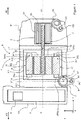
- the names “longitudinal”, “radial”, “front” and “rear” refer to the orientation, in an Oxyz orthonormal frame, of an electric compressor 1 illustrated in FIGS. FIGURES 1 to 3 .
- the axis Ox represents the longitudinal direction
- the axis Oy and the axis Oz represent radial directions of the object in question, in particular the electric compressor 1.
- a longitudinal plane is parallel to the plane Oxz or on the plane Oxy and a radial plane is parallel to the plane Oyz.
- the front and rear positions are defined along the longitudinal axis X.
- a radial position is defined as being located within a plane parallel to the plane Oyz.
- An electric compressor 1 according to the first aspect of the invention or according to any one of its improvements is more particularly intended to compress a refrigerating fluid FR flowing inside a refrigerant circuit 9 fitted to a motor vehicle, such as that illustrated on the FIGURE 4 .
- the electric compressor 1 can be used for the compression of fluids of different types, and the electric compressor 1 can be mounted on any type of circuit as mobile as fixed.
- the refrigerant circuit 9 with which the electric compressor 1 is intended to collaborate can equip any type of motorized vehicle, without restriction as to their type.
- the electric compressor 1 extends along the longitudinal axis X. It is understood here that the longitudinal axis X is the axis in which the electric compressor 1 has its largest dimension.
- the electric compressor is generally of cylindrical conformation whose axis of revolution coincides with the longitudinal axis X.
- the electric compressor 1 comprises a compression mechanism 2 which is intended to compress the refrigerant fluid FR admitted inside the electric compressor 1.
- the compression mechanism 2 comprises at least one movable element 21 which is rotated on itself to compress the refrigerant fluid FR.
- the compression mechanism 2 is a spiral mechanism comprising for example two spirals nested one inside the other, including a mobile spiral, forming the movable element 21, and a fixed spiral.
- the electric compressor 1 also comprises an electric motor 3 for driving the compression mechanism 2 in rotation.
- the electric motor 3 comprises a stator 31 which is a fixed element and a rotor 32 which is a member movable in rotation inside the stator. 31.
- the electric motor 3 also comprises a drive shaft 33 which extends along an axis of rotation A1 preferably parallel to, or even coincident with the longitudinal axis X.
- the drive shaft 33 is integral with the rotor 32.
- motor shaft 33 is also integral with the movable element 21 of the compression element 2.
- the electric compressor 1 further comprises a control module 4 which is intended to drive the electric motor 3, and in particular the rotation of the drive shaft 33.
- the control module 4 notably comprises an inverter 5 which makes it possible to convert available electrical energy. on board the motor vehicle in electrical energy adapted for the electric motor 3 of the electric compressor 1.
- the compression mechanism 2, the electric motor 3 and the control module 4 are aligned parallel to the axis of rotation A1. More specifically, the electric motor 3 is located in an axially intermediate position between the compression mechanism 2 and the control module 4. In other words, the electric motor 3 is interposed between the compression mechanism 2 and the control module 4 along. of the axis of rotation A1 of the electric motor 3.
- the left side is defined as forming the rear AR of the electric compressor 1 and the right side is defined as forming the front AV of the electric compressor 1.
- the control module 4 is located at the rear rear of the electric compressor 1 and the compression mechanism 2 is located at the front of the AV of the electric compressor 1.
- the compression mechanism 2, the electric motor 3 and the control module 4 are housed inside a housing 6 of the electric compressor 1.
- the housing 6 forms an enclosure for the housing and / or the protection of the compression mechanism 2, the electric motor 3 and the control module 4.
- the housing 6 is for example formed of an aluminum alloy.
- the housing 6 also includes not shown fastening means for fixing the electric compressor 1 to the motor vehicle on which it is mounted.
- the housing 6 comprises a first housing element 61 for storing the compression mechanism 2, a second housing element 62 for storing an electric motor 3 and a third housing element 63 for storing the control module 4.
- the elements case 61, 62, 63 and form cavities compatible with each other, so that, collectively, the housing elements 61, 62, 63 form a single cavity within which are completely housed the compression mechanism 2, the electric motor 3 and the control module 4, the refrigerant fluid circulating inside said single cavity.
- the third housing element 63 comprises a partition 631 separating the cavity of said third housing element 63 from the cavity of the second housing element 62, the cavity of the second housing element 62 and the cavity of the first housing element 61 forming together a single cavity.
- housing members 61, 62, 63 are assembled to each other by screwing, by interlocking, by snapping or any other means of assembly, preferably reversible.
- any of the housing elements 61, 62, 63 may be formed of a plastic material, such as a polycarbonate in particular.
- the housing 6 is equipped with an inlet port 7 of the refrigerant fluid FR inside the electric compressor 1.
- the inlet port 7 is arranged to allow a fluid circulation of the refrigerant fluid FR between the outside of the electric compressor and the interior of the electric compressor 1.
- the input port is the element of the housing 6 through which the refrigerant FR is admitted inside the electric compressor 1.
- the input port 7 is arranged to enable the electric compressor to be connected to the refrigerant circuit with which it is intended to collaborate, the inlet port 7 allowing the refrigerant to penetrate inside the electric compressor at the level of the second housing element 62.
- the input port 7 is generally arranged in a cylindrical barrel which is formed around an input axis A2.
- the input axis A2 is taken inside a radial plane P1 of the electric compressor 1, the radial plane P1 being orthogonal to the axis of rotation A1.
- the input port 7 has an inlet orifice 71 of the refrigerant FR which extends orthogonally to the input axis A2.
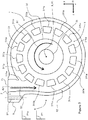
- the input port 7 is arranged tangentially to the electric motor 3. More particularly, the input port 7 is tangent to the stator 31 of the electric motor 3. As a result, the input port 7 is arranged so that tangential to the motor shaft 33 of the electric motor 3. It is understood in this that the input axis A2 is tangential to a circle C inscribed in the radial plane P1 and centered on the axis of rotation A1, as is visible on the FIGURE 2 . In other words, the axis of rotation A1 and the input axis A2 are not intersecting with each other. These provisions are such that the refrigerant FR penetrating inside the electric compressor 1 through the input port 7 flows tangentially to the electric motor 3, and more particularly to the stator 31 of the electric motor 1.
- an angle formed by the input axis A2 and the tangent to the circle C inscribed in the radial plane P1 and taken at said input port and / or at the axis of the inlet A2 is between 0 ° and 45 ° to allow the refrigerating fluid FR to flow more easily when it enters the interior of the electric compressor 1 via said inlet port 7.
- the stator 31 comprises coils 311 at least partially surrounded around a core 312.
- the coils 311 are radially distributed around the rotation shaft 33 while being extended parallel to the longitudinal axis X.
- the coils 311 are arranged at equal distance from the longitudinal axis X.
- Each coil 311 comprises two coil heads 311a, 311b formed at each of the longitudinal ends of the coil 311.
- each coil 311 is equipped with a rear coil head 311a and a front coil head 311b, each coil head 311a, 311b forming a longitudinal end of the coil 311.
- the rear coil heads 311a are at least partly enclosed or intersecting with a rear plane P1a and the coil heads rear 311b are at least partly included or intersecting with a plane before P1b, the rear plane P1a and the front plane P1b being radial planes parallel to each other.
- the input port 7 is also arranged axially between the control module 4 and the stator 31. More particularly, the input port 7 is arranged between the control module 4 and the core 312.
- the input port 7 is formed inside a radial plane P1 which is interposed between the control module 4 and the rear radial plane P1a comprising the coil heads 311a, 311b.
- the input port 7 is tangent to the coil heads 311a, 311b which form the longitudinal ends of the core 312.
- the input port 7 is arranged facing the rear coil heads 311a and tangentially to the rear coil heads 311a, so that the radial plane P1 comprising the input port 7 and the rear radial plane P1a comprising the rear coil heads 311a are merged.
- the input port 7 is arranged vis-à-vis the rear coil heads 311a.
- the coil heads 311a, 311b being the areas of the coils 311 which tend to heat up the most during the implementation of the electric compressor 1, this results in an optimization of the cooling of the electric compressor 1. Moreover, this arrangement allows also to promote the contact between the refrigerant and the partition 631 carrier of the control module 4, so as to cool it more effectively.
- the input port 7 may be arranged slightly offset from the rear coil heads 311a, either on the side of the core 312 - in the direction of the compression mechanism 2 - or on the side of the control module 4. By slightly shifted, it is understood that the input port 7 is axially offset so that said input port 7 is axially attached against an axial end of the rear coil heads 311, or the side of the core 312, or the side of the control module 4.
- a direction of rotation S1 of the drive shaft 33 and a flow direction S2 of the refrigerant FR are for example both of the same direction relative to the axis of rotation A1 of the rotor 32, and in particular trigonometric senses as illustrated on the FIGURE 3 .
- the direction of rotation S1 and the direction of movement S2 are likely to be one and the other of the clockwise directions.
- the input port 7 is provided with a protrusion 8 which forms an outer projection with respect to the longitudinal axis X.
- the protrusion 8 preferably comprises a fastener 81 of a conduit that comprises the refrigerant circuit 9 illustrated on the FIGURE 4 .
- the fastener 81 is for example formed of a cylindrical orifice adapted to receive a finger or a screw that comprises a flange for fixing the conduit inside the inlet orifice 71.
- the fastener 81 extends radially outwardly of the electric compressor 1.
- the input port 7 advantageously equips the second housing element 62 while an outlet port 10 of the refrigerant fluid FR out of the electric compressor 1 equips the first housing element 61.
- the outlet port 10 is provided with an extension 101 which preferably comprises an assembly member 102 of a duct which comprises the refrigerant circuit 9 illustrated in FIG. FIGURE 4 .
- the FIGURE 4 illustrates an exemplary embodiment of a refrigerant circuit 9 FR according to the second aspect of the invention.
- the refrigerant circuit FR is closed and the refrigerant fluid FR circulates inside said refrigerant fluid circuit FR through ducts allowing fluid circulation of the refrigerant fluid FR.
- the refrigerant circuit 9 successively comprises, according to the flow direction S2 of the refrigerant fluid FR inside the refrigerant circuit 9, the electric compressor 1 according to the first aspect of the invention and as previously described for compressing the refrigerating fluid FR, a condenser or a gas cooler 91 for cooling the refrigerant FR, an expansion member 92 inside which the cooling fluid FR undergoes a lowering of its pressure and a heat exchanger 93.
- the heat exchanger 93 is housed inside a ventilation, heating and / or air conditioning installation 94 inside which a flow of air FA circulates.
- the heat exchanger 93 allows a heat transfer between the refrigerant fluid FR and the airflow FA coming into contact with it and / or passing through it.
- the heat exchanger 93 is used as an evaporator for cooling the airflow FA, during the passage of the air flow FA to the contact and / or part of the heat exchanger 93.
- the invention relates to an electric compressor 1, an inlet port 7 of the refrigerant fluid FR in said electric compressor 1 is arranged radially with respect to the axis of rotation A1 of the rotor 32 of the electric motor 3 resulting in rotation of the compression mechanism 2 of said electric compressor 1, said input port 7 being also arranged tangentially to the electric motor 3 and located between the control module 4 and an axial end 311a of a core 312 of the stator 31 located on the side of said control module 4, in order to facilitate the fluid flow of the refrigerating fluid FR entering the electric compressor 1.
Landscapes
- Engineering & Computer Science (AREA)
- Mechanical Engineering (AREA)
- General Engineering & Computer Science (AREA)
- Compressor (AREA)
- Applications Or Details Of Rotary Compressors (AREA)
Claims (9)
- Elektrischer Kompressor (1) eines Kältemittels (FR), wobei der Elektrokompressor (1) ein Gehäuse (6) aufweist, das mindestens beherbergt:- einen Kompressionsmechanismus (2) des Kältemittels (FR);- einen Elektromotor (3) zum Betätigen des Kompressionsmechanismus (2), wobei der Elektromotor (2) einen Rotor (32), der sich um eine Drehachse (A1) dreht, und einen Stator (31) aufweist, der Spulen aufweist elektrische Drähte (311), die um einen Kern (312) gewickelt sind;- ein Steuermodul (4) zum Steuern des Elektromotors (3), wobei sich der Elektromotor (3) in einer axialen Zwischenposition zwischen dem Kompressionsmechanismus (2) und dem Steuermodul (4) befindet;wobei das Gehäuse (6) mindestens eine Einlassöffnung (7) für das Kältemittel (FR) in dem elektrischen Kompressor (1) aufweist, wobei die Einlassöffnung (7) radial in Bezug auf das Kältemittel angeordnet ist Drehung (A1) des Rotors (32), dadurch gekennzeichnet, dass der Eingangsanschluss (7) tangential zum Elektromotor (3) angeordnet ist und dass sich der Eingangsanschluss (7) zwischen dem Modul befindet Steuerung (4) und ein axiales Ende (311a) eines Kerns (312) des Stators (31), der an der Seite des Steuermoduls (4) angeordnet ist.
- Elektrischer Kompressor (1) nach dem vorhergehenden Anspruch, wobei der Eingangsanschluss (7) den Stator (31) tangiert.
- Elektrischer Kompressor (1) nach einem der vorhergehenden Ansprüche, wobei der Eingangsanschluss (7) das axiale Ende (311a) des Kerns (312) des Stators (31) tangiert.
- Elektrischer Kompressor (1) nach Anspruch 3, wobei der Eingangsanschluss (7) gegenüber dem axialen Ende (311a) des Kerns (312) des Stators (31) ausgebildet ist.
- Elektrischer Kompressor (1) nach einem der vorhergehenden Ansprüche, bei dem die Eingangsöffnung (7) in einer zylindrischen Eingangswellenwelle (A2) angeordnet ist, die einen eingravierten Kreis (C) berührt eine Radialebene (P1) und zentriert auf der Drehachse (A1).
- Elektrischer Kompressor (1) nach einem der vorhergehenden Ansprüche, wobei der Eingangsanschluss (7) einen Vorsprung (8) umfasst, der ein Befestigungselement (81) umfasst, das mit einem komplementären Befestigungselement zusammenwirken kann, das ein Mittel zum Befestigen einer Leitung.
- Elektrischer Kompressor (1) nach einem der vorhergehenden Ansprüche, wobei der Kompressionsmechanismus (2) ein Spiralmechanismus ist.
- Kältemittelkreislauf (9) mit einem elektrischen Kompressor (1) nach einem der vorhergehenden Ansprüche, einem Gaskühler (91), einem Expansionselement (92) und mindestens einem Wärmetauscher (93).
- Kältemittelkreislauf (9) nach Anspruch 8, umfassend einen elektrischen Kompressor (1), dessen Rotor (32) sich in einer Drehrichtung (S1) dreht, wobei das Kältemittel (FR) innerhalb des Fluidkreislaufs fließt Kältemittel (9) in einer Umlaufrichtung (S2), in der die Drehrichtung (S1) des Rotors (32) und die Strömungsrichtung (S2) des Kältemittels (FR) in der gleichen Richtung am Kanal liegen Eingang (7)
Applications Claiming Priority (1)
| Application Number | Priority Date | Filing Date | Title |
|---|---|---|---|
| FR1753658A FR3065758B1 (fr) | 2017-04-27 | 2017-04-27 | Compresseur electrique |
Publications (2)
| Publication Number | Publication Date |
|---|---|
| EP3396162A1 EP3396162A1 (de) | 2018-10-31 |
| EP3396162B1 true EP3396162B1 (de) | 2019-12-11 |
Family
ID=59070924
Family Applications (1)
| Application Number | Title | Priority Date | Filing Date |
|---|---|---|---|
| EP18167339.3A Active EP3396162B1 (de) | 2017-04-27 | 2018-04-13 | Elektrischer kompressor |
Country Status (2)
| Country | Link |
|---|---|
| EP (1) | EP3396162B1 (de) |
| FR (1) | FR3065758B1 (de) |
Family Cites Families (4)
| Publication number | Priority date | Publication date | Assignee | Title |
|---|---|---|---|---|
| US6908290B2 (en) * | 2003-05-01 | 2005-06-21 | Visteon Global Technologies, Inc. | Air conditioning compressor having reduced suction pulsation |
| JP5018451B2 (ja) * | 2007-12-18 | 2012-09-05 | 株式会社豊田自動織機 | 電動圧縮機 |
| EP2873858B1 (de) * | 2012-05-18 | 2020-08-12 | Valeo Japan Co., Ltd. | Elektrischer verdichter |
| FR3023328B1 (fr) * | 2014-07-07 | 2019-03-22 | Valeo Japan Co., Ltd. | Plaque d'un compresseur electrique et compresseur electrique comprenant une telle plaque |
-
2017
- 2017-04-27 FR FR1753658A patent/FR3065758B1/fr not_active Expired - Fee Related
-
2018
- 2018-04-13 EP EP18167339.3A patent/EP3396162B1/de active Active
Non-Patent Citations (1)
| Title |
|---|
| None * |
Also Published As
| Publication number | Publication date |
|---|---|
| FR3065758B1 (fr) | 2019-05-03 |
| FR3065758A1 (fr) | 2018-11-02 |
| EP3396162A1 (de) | 2018-10-31 |
Similar Documents
| Publication | Publication Date | Title |
|---|---|---|
| WO2021255103A1 (fr) | Module de refroidissement pour véhicule automobile électrique ou hybride à turbomachine tangentielle | |
| EP2667030A1 (de) | Gehäuse eines elektrischen Kompressors, das eine Dissipationsvorrichtung umfasst, und Kompressor mit einem solchen Gehäuse | |
| EP4240606B1 (de) | Kühlmodul für ein elektro- oder hybridkraftfahrzeug mit einer tangentialflussturbomaschine mit einem zusätzlichen wärmetauscher | |
| WO2017187046A1 (fr) | Systeme de gestion d'air d'admission pour un moteur thermique de véhicule automobile | |
| EP3396162B1 (de) | Elektrischer kompressor | |
| WO2010063897A1 (fr) | Echangeur de chaleur à spires et dispositif de climatisation comprenant un tel échangeur de chaleur. | |
| EP4314563B1 (de) | Kühlmodul für ein elektro- oder hybridkraftfahrzeug mit einer tangentialflussturbomaschine | |
| WO2024083565A1 (fr) | Module de refroidissement pour véhicule automobile électrique ou hybride | |
| FR3132468A1 (fr) | Dispositif de gestion thermique pour véhicule automobile électrique ou hybride | |
| WO2018060615A1 (fr) | Système de gestion d'air d'admission pour un moteur thermique de véhicule automobile | |
| FR3113699A1 (fr) | Module de refroidissement pour véhicule automobile électrique à turbomachine tangentielle | |
| WO2022023012A1 (fr) | Module de refroidissement pour véhicule automobile électrique ou hybride | |
| WO2022106147A1 (fr) | Module de refroidissement pour véhicule automobile électrique ou hybride à turbomachine tangentielle avec échangeur de chaleur supplémentaire | |
| WO2022053501A1 (fr) | Module d'échange thermique et véhicule automobile correspondant | |
| FR3055366B1 (fr) | Systeme de gestion d'air d'admission pour un moteur thermique de vehicule automobile | |
| EP4313640A1 (de) | Heizungs-, lüftungs- und/oder klimaanlage für ein kraftfahrzeug | |
| WO2016005890A1 (fr) | Plaque d'un compresseur électrique et compresseur électrique comprenant une telle plaque | |
| WO2024235889A1 (fr) | Guide d'air et module de refroidissement pour véhicule automobile | |
| WO2025056221A1 (fr) | Ensemble de machine électrique pour un véhicule automobile comprenant au moins une machine électrique à flux axial et au moins un dispositif d'échange thermique | |
| FR3121076A1 (fr) | Module de refroidissement pour véhicule automobile électrique ou hybride à turbomachine tangentielle avec refroidissement de l’électronique de puissance | |
| FR3114049A1 (fr) | Ensemble de modules de refroidissement à turbomachine tangentielle pour face avant de véhicule automobile électrique ou hybride | |
| WO2003038285A1 (fr) | Groupe moto-ventilateur | |
| FR2831930A1 (fr) | Groupe moto-ventilateur comportant un module de commande integre universel |
Legal Events
| Date | Code | Title | Description |
|---|---|---|---|
| PUAI | Public reference made under article 153(3) epc to a published international application that has entered the european phase |
Free format text: ORIGINAL CODE: 0009012 |
|
| STAA | Information on the status of an ep patent application or granted ep patent |
Free format text: STATUS: THE APPLICATION HAS BEEN PUBLISHED |
|
| AK | Designated contracting states |
Kind code of ref document: A1 Designated state(s): AL AT BE BG CH CY CZ DE DK EE ES FI FR GB GR HR HU IE IS IT LI LT LU LV MC MK MT NL NO PL PT RO RS SE SI SK SM TR |
|
| AX | Request for extension of the european patent |
Extension state: BA ME |
|
| STAA | Information on the status of an ep patent application or granted ep patent |
Free format text: STATUS: REQUEST FOR EXAMINATION WAS MADE |
|
| 17P | Request for examination filed |
Effective date: 20190415 |
|
| RBV | Designated contracting states (corrected) |
Designated state(s): AL AT BE BG CH CY CZ DE DK EE ES FI FR GB GR HR HU IE IS IT LI LT LU LV MC MK MT NL NO PL PT RO RS SE SI SK SM TR |
|
| GRAP | Despatch of communication of intention to grant a patent |
Free format text: ORIGINAL CODE: EPIDOSNIGR1 |
|
| STAA | Information on the status of an ep patent application or granted ep patent |
Free format text: STATUS: GRANT OF PATENT IS INTENDED |
|
| RIC1 | Information provided on ipc code assigned before grant |
Ipc: F04C 29/12 20060101ALI20190523BHEP Ipc: F04B 39/06 20060101ALI20190523BHEP Ipc: F04C 23/00 20060101AFI20190523BHEP Ipc: F04C 29/04 20060101ALI20190523BHEP |
|
| INTG | Intention to grant announced |
Effective date: 20190624 |
|
| GRAS | Grant fee paid |
Free format text: ORIGINAL CODE: EPIDOSNIGR3 |
|
| GRAA | (expected) grant |
Free format text: ORIGINAL CODE: 0009210 |
|
| STAA | Information on the status of an ep patent application or granted ep patent |
Free format text: STATUS: THE PATENT HAS BEEN GRANTED |
|
| AK | Designated contracting states |
Kind code of ref document: B1 Designated state(s): AL AT BE BG CH CY CZ DE DK EE ES FI FR GB GR HR HU IE IS IT LI LT LU LV MC MK MT NL NO PL PT RO RS SE SI SK SM TR |
|
| REG | Reference to a national code |
Ref country code: GB Ref legal event code: FG4D Free format text: NOT ENGLISH |
|
| REG | Reference to a national code |
Ref country code: CH Ref legal event code: EP |
|
| REG | Reference to a national code |
Ref country code: AT Ref legal event code: REF Ref document number: 1212459 Country of ref document: AT Kind code of ref document: T Effective date: 20191215 |
|
| REG | Reference to a national code |
Ref country code: DE Ref legal event code: R096 Ref document number: 602018001539 Country of ref document: DE |
|
| REG | Reference to a national code |
Ref country code: IE Ref legal event code: FG4D Free format text: LANGUAGE OF EP DOCUMENT: FRENCH |
|
| REG | Reference to a national code |
Ref country code: NL Ref legal event code: MP Effective date: 20191211 |
|
| REG | Reference to a national code |
Ref country code: LT Ref legal event code: MG4D |
|
| PG25 | Lapsed in a contracting state [announced via postgrant information from national office to epo] |
Ref country code: NO Free format text: LAPSE BECAUSE OF FAILURE TO SUBMIT A TRANSLATION OF THE DESCRIPTION OR TO PAY THE FEE WITHIN THE PRESCRIBED TIME-LIMIT Effective date: 20200311 Ref country code: LT Free format text: LAPSE BECAUSE OF FAILURE TO SUBMIT A TRANSLATION OF THE DESCRIPTION OR TO PAY THE FEE WITHIN THE PRESCRIBED TIME-LIMIT Effective date: 20191211 Ref country code: GR Free format text: LAPSE BECAUSE OF FAILURE TO SUBMIT A TRANSLATION OF THE DESCRIPTION OR TO PAY THE FEE WITHIN THE PRESCRIBED TIME-LIMIT Effective date: 20200312 Ref country code: SE Free format text: LAPSE BECAUSE OF FAILURE TO SUBMIT A TRANSLATION OF THE DESCRIPTION OR TO PAY THE FEE WITHIN THE PRESCRIBED TIME-LIMIT Effective date: 20191211 Ref country code: LV Free format text: LAPSE BECAUSE OF FAILURE TO SUBMIT A TRANSLATION OF THE DESCRIPTION OR TO PAY THE FEE WITHIN THE PRESCRIBED TIME-LIMIT Effective date: 20191211 Ref country code: BG Free format text: LAPSE BECAUSE OF FAILURE TO SUBMIT A TRANSLATION OF THE DESCRIPTION OR TO PAY THE FEE WITHIN THE PRESCRIBED TIME-LIMIT Effective date: 20200311 Ref country code: FI Free format text: LAPSE BECAUSE OF FAILURE TO SUBMIT A TRANSLATION OF THE DESCRIPTION OR TO PAY THE FEE WITHIN THE PRESCRIBED TIME-LIMIT Effective date: 20191211 |
|
| PG25 | Lapsed in a contracting state [announced via postgrant information from national office to epo] |
Ref country code: RS Free format text: LAPSE BECAUSE OF FAILURE TO SUBMIT A TRANSLATION OF THE DESCRIPTION OR TO PAY THE FEE WITHIN THE PRESCRIBED TIME-LIMIT Effective date: 20191211 Ref country code: HR Free format text: LAPSE BECAUSE OF FAILURE TO SUBMIT A TRANSLATION OF THE DESCRIPTION OR TO PAY THE FEE WITHIN THE PRESCRIBED TIME-LIMIT Effective date: 20191211 |
|
| PG25 | Lapsed in a contracting state [announced via postgrant information from national office to epo] |
Ref country code: AL Free format text: LAPSE BECAUSE OF FAILURE TO SUBMIT A TRANSLATION OF THE DESCRIPTION OR TO PAY THE FEE WITHIN THE PRESCRIBED TIME-LIMIT Effective date: 20191211 |
|
| PG25 | Lapsed in a contracting state [announced via postgrant information from national office to epo] |
Ref country code: ES Free format text: LAPSE BECAUSE OF FAILURE TO SUBMIT A TRANSLATION OF THE DESCRIPTION OR TO PAY THE FEE WITHIN THE PRESCRIBED TIME-LIMIT Effective date: 20191211 Ref country code: PT Free format text: LAPSE BECAUSE OF FAILURE TO SUBMIT A TRANSLATION OF THE DESCRIPTION OR TO PAY THE FEE WITHIN THE PRESCRIBED TIME-LIMIT Effective date: 20200506 Ref country code: NL Free format text: LAPSE BECAUSE OF FAILURE TO SUBMIT A TRANSLATION OF THE DESCRIPTION OR TO PAY THE FEE WITHIN THE PRESCRIBED TIME-LIMIT Effective date: 20191211 Ref country code: CZ Free format text: LAPSE BECAUSE OF FAILURE TO SUBMIT A TRANSLATION OF THE DESCRIPTION OR TO PAY THE FEE WITHIN THE PRESCRIBED TIME-LIMIT Effective date: 20191211 Ref country code: RO Free format text: LAPSE BECAUSE OF FAILURE TO SUBMIT A TRANSLATION OF THE DESCRIPTION OR TO PAY THE FEE WITHIN THE PRESCRIBED TIME-LIMIT Effective date: 20191211 Ref country code: EE Free format text: LAPSE BECAUSE OF FAILURE TO SUBMIT A TRANSLATION OF THE DESCRIPTION OR TO PAY THE FEE WITHIN THE PRESCRIBED TIME-LIMIT Effective date: 20191211 |
|
| PG25 | Lapsed in a contracting state [announced via postgrant information from national office to epo] |
Ref country code: IS Free format text: LAPSE BECAUSE OF FAILURE TO SUBMIT A TRANSLATION OF THE DESCRIPTION OR TO PAY THE FEE WITHIN THE PRESCRIBED TIME-LIMIT Effective date: 20200411 Ref country code: SK Free format text: LAPSE BECAUSE OF FAILURE TO SUBMIT A TRANSLATION OF THE DESCRIPTION OR TO PAY THE FEE WITHIN THE PRESCRIBED TIME-LIMIT Effective date: 20191211 Ref country code: SM Free format text: LAPSE BECAUSE OF FAILURE TO SUBMIT A TRANSLATION OF THE DESCRIPTION OR TO PAY THE FEE WITHIN THE PRESCRIBED TIME-LIMIT Effective date: 20191211 |
|
| REG | Reference to a national code |
Ref country code: DE Ref legal event code: R097 Ref document number: 602018001539 Country of ref document: DE |
|
| REG | Reference to a national code |
Ref country code: AT Ref legal event code: MK05 Ref document number: 1212459 Country of ref document: AT Kind code of ref document: T Effective date: 20191211 |
|
| PLBE | No opposition filed within time limit |
Free format text: ORIGINAL CODE: 0009261 |
|
| STAA | Information on the status of an ep patent application or granted ep patent |
Free format text: STATUS: NO OPPOSITION FILED WITHIN TIME LIMIT |
|
| PG25 | Lapsed in a contracting state [announced via postgrant information from national office to epo] |
Ref country code: DK Free format text: LAPSE BECAUSE OF FAILURE TO SUBMIT A TRANSLATION OF THE DESCRIPTION OR TO PAY THE FEE WITHIN THE PRESCRIBED TIME-LIMIT Effective date: 20191211 |
|
| 26N | No opposition filed |
Effective date: 20200914 |
|
| PG25 | Lapsed in a contracting state [announced via postgrant information from national office to epo] |
Ref country code: AT Free format text: LAPSE BECAUSE OF FAILURE TO SUBMIT A TRANSLATION OF THE DESCRIPTION OR TO PAY THE FEE WITHIN THE PRESCRIBED TIME-LIMIT Effective date: 20191211 Ref country code: MC Free format text: LAPSE BECAUSE OF FAILURE TO SUBMIT A TRANSLATION OF THE DESCRIPTION OR TO PAY THE FEE WITHIN THE PRESCRIBED TIME-LIMIT Effective date: 20191211 Ref country code: SI Free format text: LAPSE BECAUSE OF FAILURE TO SUBMIT A TRANSLATION OF THE DESCRIPTION OR TO PAY THE FEE WITHIN THE PRESCRIBED TIME-LIMIT Effective date: 20191211 |
|
| PG25 | Lapsed in a contracting state [announced via postgrant information from national office to epo] |
Ref country code: LU Free format text: LAPSE BECAUSE OF NON-PAYMENT OF DUE FEES Effective date: 20200413 Ref country code: IT Free format text: LAPSE BECAUSE OF FAILURE TO SUBMIT A TRANSLATION OF THE DESCRIPTION OR TO PAY THE FEE WITHIN THE PRESCRIBED TIME-LIMIT Effective date: 20191211 |
|
| REG | Reference to a national code |
Ref country code: BE Ref legal event code: MM Effective date: 20200430 |
|
| PG25 | Lapsed in a contracting state [announced via postgrant information from national office to epo] |
Ref country code: BE Free format text: LAPSE BECAUSE OF NON-PAYMENT OF DUE FEES Effective date: 20200430 Ref country code: PL Free format text: LAPSE BECAUSE OF FAILURE TO SUBMIT A TRANSLATION OF THE DESCRIPTION OR TO PAY THE FEE WITHIN THE PRESCRIBED TIME-LIMIT Effective date: 20191211 |
|
| PG25 | Lapsed in a contracting state [announced via postgrant information from national office to epo] |
Ref country code: IE Free format text: LAPSE BECAUSE OF NON-PAYMENT OF DUE FEES Effective date: 20200413 |
|
| PG25 | Lapsed in a contracting state [announced via postgrant information from national office to epo] |
Ref country code: CH Free format text: LAPSE BECAUSE OF NON-PAYMENT OF DUE FEES Effective date: 20210430 Ref country code: LI Free format text: LAPSE BECAUSE OF NON-PAYMENT OF DUE FEES Effective date: 20210430 |
|
| PG25 | Lapsed in a contracting state [announced via postgrant information from national office to epo] |
Ref country code: TR Free format text: LAPSE BECAUSE OF FAILURE TO SUBMIT A TRANSLATION OF THE DESCRIPTION OR TO PAY THE FEE WITHIN THE PRESCRIBED TIME-LIMIT Effective date: 20191211 Ref country code: MT Free format text: LAPSE BECAUSE OF FAILURE TO SUBMIT A TRANSLATION OF THE DESCRIPTION OR TO PAY THE FEE WITHIN THE PRESCRIBED TIME-LIMIT Effective date: 20191211 Ref country code: CY Free format text: LAPSE BECAUSE OF FAILURE TO SUBMIT A TRANSLATION OF THE DESCRIPTION OR TO PAY THE FEE WITHIN THE PRESCRIBED TIME-LIMIT Effective date: 20191211 |
|
| PG25 | Lapsed in a contracting state [announced via postgrant information from national office to epo] |
Ref country code: MK Free format text: LAPSE BECAUSE OF FAILURE TO SUBMIT A TRANSLATION OF THE DESCRIPTION OR TO PAY THE FEE WITHIN THE PRESCRIBED TIME-LIMIT Effective date: 20191211 |
|
| GBPC | Gb: european patent ceased through non-payment of renewal fee |
Effective date: 20220413 |
|
| PG25 | Lapsed in a contracting state [announced via postgrant information from national office to epo] |
Ref country code: GB Free format text: LAPSE BECAUSE OF NON-PAYMENT OF DUE FEES Effective date: 20220413 |
|
| P01 | Opt-out of the competence of the unified patent court (upc) registered |
Effective date: 20230629 |
|
| PGFP | Annual fee paid to national office [announced via postgrant information from national office to epo] |
Ref country code: DE Payment date: 20250411 Year of fee payment: 8 |
|
| PGFP | Annual fee paid to national office [announced via postgrant information from national office to epo] |
Ref country code: FR Payment date: 20250429 Year of fee payment: 8 |