EP3396168B1 - Dispositif pompe immergé de petites dimensions - Google Patents
Dispositif pompe immergé de petites dimensions Download PDFInfo
- Publication number
- EP3396168B1 EP3396168B1 EP16879467.5A EP16879467A EP3396168B1 EP 3396168 B1 EP3396168 B1 EP 3396168B1 EP 16879467 A EP16879467 A EP 16879467A EP 3396168 B1 EP3396168 B1 EP 3396168B1
- Authority
- EP
- European Patent Office
- Prior art keywords
- submersible
- pump unit
- submersible pump
- motor
- unit according
- Prior art date
- Legal status (The legal status is an assumption and is not a legal conclusion. Google has not performed a legal analysis and makes no representation as to the accuracy of the status listed.)
- Not-in-force
Links
Images



Classifications
-
- F—MECHANICAL ENGINEERING; LIGHTING; HEATING; WEAPONS; BLASTING
- F04—POSITIVE - DISPLACEMENT MACHINES FOR LIQUIDS; PUMPS FOR LIQUIDS OR ELASTIC FLUIDS
- F04D—NON-POSITIVE-DISPLACEMENT PUMPS
- F04D13/00—Pumping installations or systems
- F04D13/02—Units comprising pumps and their driving means
- F04D13/06—Units comprising pumps and their driving means the pump being electrically driven
- F04D13/08—Units comprising pumps and their driving means the pump being electrically driven for submerged use
- F04D13/086—Units comprising pumps and their driving means the pump being electrically driven for submerged use the pump and drive motor are both submerged
-
- F—MECHANICAL ENGINEERING; LIGHTING; HEATING; WEAPONS; BLASTING
- F04—POSITIVE - DISPLACEMENT MACHINES FOR LIQUIDS; PUMPS FOR LIQUIDS OR ELASTIC FLUIDS
- F04D—NON-POSITIVE-DISPLACEMENT PUMPS
- F04D13/00—Pumping installations or systems
- F04D13/02—Units comprising pumps and their driving means
- F04D13/06—Units comprising pumps and their driving means the pump being electrically driven
- F04D13/08—Units comprising pumps and their driving means the pump being electrically driven for submerged use
- F04D13/10—Units comprising pumps and their driving means the pump being electrically driven for submerged use adapted for use in mining bore holes
-
- E—FIXED CONSTRUCTIONS
- E21—EARTH OR ROCK DRILLING; MINING
- E21B—EARTH OR ROCK DRILLING; OBTAINING OIL, GAS, WATER, SOLUBLE OR MELTABLE MATERIALS OR A SLURRY OF MINERALS FROM WELLS
- E21B43/00—Methods or apparatus for obtaining oil, gas, water, soluble or meltable materials or a slurry of minerals from wells
- E21B43/12—Methods or apparatus for controlling the flow of the obtained fluid to or in wells
- E21B43/121—Lifting well fluids
- E21B43/128—Adaptation of pump systems with down-hole electric drives
-
- F—MECHANICAL ENGINEERING; LIGHTING; HEATING; WEAPONS; BLASTING
- F04—POSITIVE - DISPLACEMENT MACHINES FOR LIQUIDS; PUMPS FOR LIQUIDS OR ELASTIC FLUIDS
- F04D—NON-POSITIVE-DISPLACEMENT PUMPS
- F04D29/00—Details, component parts, or accessories
- F04D29/08—Sealings
- F04D29/086—Sealings especially adapted for liquid pumps
-
- F—MECHANICAL ENGINEERING; LIGHTING; HEATING; WEAPONS; BLASTING
- F04—POSITIVE - DISPLACEMENT MACHINES FOR LIQUIDS; PUMPS FOR LIQUIDS OR ELASTIC FLUIDS
- F04D—NON-POSITIVE-DISPLACEMENT PUMPS
- F04D29/00—Details, component parts, or accessories
- F04D29/40—Casings; Connections of working fluid
- F04D29/406—Casings; Connections of working fluid especially adapted for liquid pumps
-
- F—MECHANICAL ENGINEERING; LIGHTING; HEATING; WEAPONS; BLASTING
- F04—POSITIVE - DISPLACEMENT MACHINES FOR LIQUIDS; PUMPS FOR LIQUIDS OR ELASTIC FLUIDS
- F04D—NON-POSITIVE-DISPLACEMENT PUMPS
- F04D29/00—Details, component parts, or accessories
- F04D29/40—Casings; Connections of working fluid
- F04D29/42—Casings; Connections of working fluid for radial or helico-centrifugal pumps
- F04D29/426—Casings; Connections of working fluid for radial or helico-centrifugal pumps especially adapted for liquid pumps
-
- F—MECHANICAL ENGINEERING; LIGHTING; HEATING; WEAPONS; BLASTING
- F04—POSITIVE - DISPLACEMENT MACHINES FOR LIQUIDS; PUMPS FOR LIQUIDS OR ELASTIC FLUIDS
- F04D—NON-POSITIVE-DISPLACEMENT PUMPS
- F04D29/00—Details, component parts, or accessories
- F04D29/40—Casings; Connections of working fluid
- F04D29/52—Casings; Connections of working fluid for axial pumps
- F04D29/528—Casings; Connections of working fluid for axial pumps especially adapted for liquid pumps
-
- F—MECHANICAL ENGINEERING; LIGHTING; HEATING; WEAPONS; BLASTING
- F04—POSITIVE - DISPLACEMENT MACHINES FOR LIQUIDS; PUMPS FOR LIQUIDS OR ELASTIC FLUIDS
- F04D—NON-POSITIVE-DISPLACEMENT PUMPS
- F04D29/00—Details, component parts, or accessories
- F04D29/60—Mounting; Assembling; Disassembling
- F04D29/62—Mounting; Assembling; Disassembling of radial or helico-centrifugal pumps
- F04D29/628—Mounting; Assembling; Disassembling of radial or helico-centrifugal pumps especially adapted for liquid pumps
-
- F—MECHANICAL ENGINEERING; LIGHTING; HEATING; WEAPONS; BLASTING
- F04—POSITIVE - DISPLACEMENT MACHINES FOR LIQUIDS; PUMPS FOR LIQUIDS OR ELASTIC FLUIDS
- F04D—NON-POSITIVE-DISPLACEMENT PUMPS
- F04D29/00—Details, component parts, or accessories
- F04D29/60—Mounting; Assembling; Disassembling
- F04D29/64—Mounting; Assembling; Disassembling of axial pumps
- F04D29/648—Mounting; Assembling; Disassembling of axial pumps especially adapted for liquid pumps
-
- F—MECHANICAL ENGINEERING; LIGHTING; HEATING; WEAPONS; BLASTING
- F04—POSITIVE - DISPLACEMENT MACHINES FOR LIQUIDS; PUMPS FOR LIQUIDS OR ELASTIC FLUIDS
- F04D—NON-POSITIVE-DISPLACEMENT PUMPS
- F04D29/00—Details, component parts, or accessories
- F04D29/70—Suction grids; Strainers; Dust separation; Cleaning
- F04D29/708—Suction grids; Strainers; Dust separation; Cleaning specially for liquid pumps
-
- F—MECHANICAL ENGINEERING; LIGHTING; HEATING; WEAPONS; BLASTING
- F16—ENGINEERING ELEMENTS AND UNITS; GENERAL MEASURES FOR PRODUCING AND MAINTAINING EFFECTIVE FUNCTIONING OF MACHINES OR INSTALLATIONS; THERMAL INSULATION IN GENERAL
- F16L—PIPES; JOINTS OR FITTINGS FOR PIPES; SUPPORTS FOR PIPES, CABLES OR PROTECTIVE TUBING; MEANS FOR THERMAL INSULATION IN GENERAL
- F16L37/00—Couplings of the quick-acting type
- F16L37/08—Couplings of the quick-acting type in which the connection between abutting or axially overlapping ends is maintained by locking members
- F16L37/12—Couplings of the quick-acting type in which the connection between abutting or axially overlapping ends is maintained by locking members using hooks, pawls, or other movable or insertable locking members
- F16L37/138—Couplings of the quick-acting type in which the connection between abutting or axially overlapping ends is maintained by locking members using hooks, pawls, or other movable or insertable locking members using an axially movable sleeve
-
- F—MECHANICAL ENGINEERING; LIGHTING; HEATING; WEAPONS; BLASTING
- F16—ENGINEERING ELEMENTS AND UNITS; GENERAL MEASURES FOR PRODUCING AND MAINTAINING EFFECTIVE FUNCTIONING OF MACHINES OR INSTALLATIONS; THERMAL INSULATION IN GENERAL
- F16L—PIPES; JOINTS OR FITTINGS FOR PIPES; SUPPORTS FOR PIPES, CABLES OR PROTECTIVE TUBING; MEANS FOR THERMAL INSULATION IN GENERAL
- F16L37/00—Couplings of the quick-acting type
- F16L37/22—Couplings of the quick-acting type in which the connection is maintained by means of balls, rollers or helical springs under radial pressure between the parts
-
- F—MECHANICAL ENGINEERING; LIGHTING; HEATING; WEAPONS; BLASTING
- F16—ENGINEERING ELEMENTS AND UNITS; GENERAL MEASURES FOR PRODUCING AND MAINTAINING EFFECTIVE FUNCTIONING OF MACHINES OR INSTALLATIONS; THERMAL INSULATION IN GENERAL
- F16L—PIPES; JOINTS OR FITTINGS FOR PIPES; SUPPORTS FOR PIPES, CABLES OR PROTECTIVE TUBING; MEANS FOR THERMAL INSULATION IN GENERAL
- F16L37/00—Couplings of the quick-acting type
- F16L37/08—Couplings of the quick-acting type in which the connection between abutting or axially overlapping ends is maintained by locking members
- F16L37/12—Couplings of the quick-acting type in which the connection between abutting or axially overlapping ends is maintained by locking members using hooks, pawls, or other movable or insertable locking members
- F16L37/14—Joints secured by inserting between mating surfaces an element, e.g. a piece of wire, a pin, a chain
Definitions
- the invention relates to oil production equipment, more particularly, to small-sized submersible pump units that are run in holes on a carrying cable within an additional pipe.
- Submersible pump unit designed for pumping out of oil-water-gas mixture from wells that have engineering constraints in the form of reduced flow area the stock of which inevitably grows as fields maturate, and from offshoots the diameter of which is less than the diameter of the vertical well bore are known in the prior art.
- a submersible pump unit run in a casing pipe on a carrying cable comprising of a load-bearing coupling, oil-filled submersible motor, motor seal, shiftable module, centrifugal pump, inlet module and a packer with a valve ( US 4928771 published on 29.05.1990 ).
- the disadvantage of said submersible pump unit is that when it is operated the casing pipe is affected by high pressure of the fluid being pumped out that is equal to the discharge pressure of a pump. Furthermore, the casing pipe is affected by corrosion, wear, and deposition of hardness and paraffin is possible on its surface. Also, flangeless coupling is not disclosed in this solution.
- submersible pump unit The disadvantage of such submersible pump unit is low reliability of the oil-filled submersible motor due to low oil capacity within single motor seal. Furthermore, the submersible unit is used, for the most part, to pump out iodine-bromide water deposited near the surface that contains no mechanical inclusions since the check valve located at the lower part of the suction duct does not prevent the motor from clogging. Also, flangeless coupling is not disclosed in this solution.
- the disadvantage of the submersible pump unit is that low location of the motor provides for installation of electric supply cable outside the pump section and motor seal. This makes the pump unit dimensions bigger and results in increase of the additional pipe diameter and, consequently, the diameter of a pipe the unit is run in. Furthermore, a cable installed within the annular clearance between the pump unit, motor seal and additional pipe requires anti-corrosion protection since the velocity of liquid being pumped out in the flow part may reach up to tens of meters a second. Also, flangeless coupling is not disclosed in this solution.
- Small-sized submersible pump unit run on a carrying cable comprising a load-bearing coupling, submersible telemetry unit, submersible oil-filled motor, electromagnetic coupling, motor seal, flexible coupling, shiftable module, pump and back end connected together using a threaded flangeless coupling ( US 2014/0069629 published on 13.03.2014).
- the disadvantage of the submersible pump unit taken as a prototype is its poor reliability during operation which can be principally explained by reduced inner diameter of flow area at the threaded connection portion that results in reduction of volume of formation fluid lifted to the surface which is accompanied by overheating of the submersible motor.
- Usage of threaded flangeless coupling of housings and components thereof requires their accurate axial alignment prior to coupling and usage of special tools that makes mounting more difficult and increases the time of the unit mounting on a well.
- a submersible pump according to the preamble of claim 1 is disclosed in RU2310772 (published on 20.11.2007).
- the technical problem is improvement of the pump unit functioning reliability and improvement of mounting convenience.
- the technical result is improvement of reliability of small-sized submersible pump unit in operation, elimination of submersible motor overheating, and simplification of the pump unit mounting.
- Flangeless coupling of the claimed design guarantees stability of the flow area diameter without reduction of the volume of formation fluid being lifted to the surface and, therefore, excludes overheating of the submersible oil-filled motor.
- flangeless coupling of the claimed design provides for reliable connection of the small-sized submersible pump unit components, is simple, readily producible and convenient for mounting on a well.
- protection of the pump unit against hydraulic impacts during running, and against ingress of formation fluid during operation is provided, as well as elimination of mechanical wear and jamming of operating devices of the pump unit which is achieved by installation of additional upper motor seal over the submersible telemetry unit, and the shiftable module houses a check valve.
- Additional upper motor seal of the claimed design functioning in tandem with the lower motor seal provides reliable protection against ingress of formation fluid to inner cavities of the submersible oil-filled motor, quick-operating compensation for oil volume change with pressure equalization caused by temperature fluctuations during operation, and against the unit motor stopping.
- check valve located in the shiftable module prevents mechanical particles from the additional column from deposition at the upper pump stages, thus providing protection of the pump operating devices from wear and improving reliability of the small-sized pump unit during operation process.
- a small-sized submersible pump unit comprising a submersible motor, shiftable module, and pump, the housings of which are connected with each other by flangeless couplings is provided, for which a flangeless coupling is designed with embedded ring segments as it is defined in claim 1.
- Additional aspects disclose that a submersible telemetry unit is installed over the submersible motor.
- the upper motor seal has a leak-tight central duct with electric conductors the ends of which are fastened in receptacles.
- the pump unit additionally comprises a lower motor seal between the submersible motor and the shiftable module.
- the pump unit additionally comprises a load-bearing coupling.
- the pump unit additionally comprises a back end.
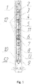
- load-bearing coupling 2 upper motor seal 3, submersible telemetry unit 4, oil-filled submersible motor 5, lower motor seal 6, shiftable module 7, centrifugal pump 8, back end 9 with external seal element 10 connected by means of capillary tubing 11 with submersible telemetry unit 4 are connected in series to carrying cable 1 in the claimed small-sized submersible pump unit.
- Component housings of small-sized submersible pump unit have the outer diameter of 55 mm and are joined together by means of flangeless couplings. The submersible pump unit is placed in additional pipe 13 with the inner diameter of 66 mm.
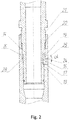
- Each component housing of the unit has covered and covering parts at the opposite ends joined by means of flangeless coupling, 14 and 15 correspondingly.
- Embedded ring segments 16 are put in the cavity formed by blind rectangular grooves 17 provided in covered part 14 of the housing and by rectangular through-opening 18 in covering part 15 of the adjacent housing.
- embedded ring segments 16 in the amount of 3 pieces are located at regular intervals from each other in circumferential direction.
- Embedded ring segments 16 are adjacent to the bottom and cross walls of blind groove 17, and their cylindrical external surface 19 is flush with covered part 14 of the housing and is overlaid by covering part 15 of the adjacent housing which is fastened by sleeve nut 20 screwed at external thread 21 of covered part 14 of the housing.
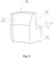
- embedded ring segment 16 may be attached to spring split bushing 22 put on covering part 15 of the adjacent housing, moreover, lead tapered internal surface 23 is made at embedded ring segment 16.
- Shape and dimensions of embedded ring segment 16 are determined on the basis of strength calculations.
- Step 24 of cylindrical external surface 19 of embedded ring segment 16 is inclined to groove 17 from diametral plane at ⁇ angle of 8-12 degrees.
- Angled wall 25 adjacent to step 24 has the same inclination angle of through opening 18 ensuring the maximum contacting surface of covering part 15 of the housing with embedded ring segment 16.
- Embedded ring segment 16 may be connected to spring split bushing 22 serving as an attachment point by means of sliding joint using screw 26.
- Spring split bushing 22 is installed at grooved part 27 of covering part 15 and is capable of moving in axial and circumferential directions.
- External thread 21 at covered part 14 of the housing ends near the face plane of covering part 15 of the housing.
- Covering part 15 of the housing is equipped with rest 28 fastening the position at which through opening 18 aligns with blind groove 17.
- the outer diameter of flangeless coupling 12 does not exceed the housing diameter of any submersible pump unit component and pump flow area 8 in the junction points of housings has no reduction that allows saving of pumped formation fluid volume.
- Upper motor seal 3 located above submersible motor 5 comprises assembled housing 29 with head 30 and bed 31 at the ends.
- Labyrinth style chamber 32, nipple 33, and flexible diaphragm 34 sealably fastened at lower support 35 are sequentially arranged below head 30.
- Leak-tight central duct 36 through internal cavities of head 30, upper support 37 and lower support 35, as well as through central holes of nipple 33 and beds 31 is formed along the axis of upper motor seal 3.
- Labyrinth style chamber 32 located between nipple 33 and head 30 has upper support 37, tube 38 inserted into head 30 and hydraulically connected to inner annulus (formation fluid) by means of valve 39 connected with hole 40.
- Head 30 has duct 41 for oil flow connecting labyrinth style 32 with hole 42 sealed with plug and designed for air removal in case of oil filling of motor seal cavities and motor 5 during installation.
- Diaphragm vessel 43 is formed around diaphragm 34.
- Depressurizing check valve 45 is installed in nipple lower part 33 inside fluid passage 44.
- Passage 44 in the upper part is connected to inner annulus for air removal through hole 46 sealed with a plug, as well as to leak-tight central duct 36.
- Isolated electric conductors 47 are laid inside oil-filled leak-tight central duct 36. Upper and lower ends of conductors 47 are attached by means of threaded connection to liners 48 located in receptacles 49 arranged in head 30 and bed 31.
- Electric conductors 47 in upper motor seal 4, submersible telemetry unit 4 and submersible motor 5 are arranged within the loop limited by flangeless coupling 12, thereby the submersible pump unit with dimensions of 55 mm maximum may be used.
- Check valve 51 with possibility of duct 50 closure is installed in outlet duct 50 of shiftable module 7 in order to prevent entering of fine particles from additional pipe 13 into pump 8.
- seal element 10 between back end 9 and additional pipe 13 may be provided by means of elastomeric coating expanding when contacting with formation fluid or mechanical packer.
- Well strainer 52 is connected to back end 9 for work in the wells with high content of solid particles.
- Submersible pump unit is mounted as follows.
- Additional pipe 13 with the inner diameter of 66 mm is put to the design depth into the casing pipe with engineering constraints and is fastened at the well head by means of X-mas tree. Then the submersible pump unit components housings of which have the outer diameter of 55 mm are run in additional pipe 13 in sequence starting with back end 9 with attached external seal element 10 and capillary tubing 11. Upper end of capillary tubing 11 is connected to submersible telemetry unit 4. Load-bearing coupling 2 with carrying cable 1 are run in last of all. Unit components are joined together by means of flangeless couplings 12 which are mounted in sequence at covered 14 and covering 15 parts of the adjacent housings, more particularly, 8-7, 7-6, 6-5, 5-4, 4-3, 3-2 in the following sequence.
- Covered part 14 of the housing with screwed on sleeve nut 20 is inserted into covering part 15 of the adjacent housing, matching their blind groove 17 and through-opening 18 and putting embedded ring segments 16 into the formed cavities.
- Embedded ring segments 16 are preliminary arranged at spring split bushing 22 in order to ease the installation by excluding manual embedding.
- Cylindrical drilling-through 19 at embedded ring segments 16 are overlaid by covering part 15 of the adjacent housing during further axial movement of covered part 14. Fastening of embedded ring segments 16 and correspondingly position of the adjacent housings are provided by sleeve nut 20 moving along external thread 21. As a result mutual axial and radial offsets of the connected unit component housings are avoided.
- Upper motor seal 3 functioning in tandem with lower motor seal 6 provides reliable protection against ingress of formation fluid to inner cavities of submersible oil-filled motor 5, quick-operating compensation for oil volume change with pressure equalization caused by temperature fluctuations during operation, and against motor 5 stopping as a part of the pump unit.
- Measurement of pump 8 inlet pressure is provided due to capillary tubing 11 connecting back end 9 with submersible telemetry unit 4.
- Check valve 51 in shiftable module 7 and outlet duct 50 are closed thereby preventing deposition of mechanical particles at the upper stages of pump 8 from additional column 13 when pump 8 is turned off, for example in case of blockage of well strainer 52 when exposed to the formation fluid head in additional column 13.
- the formation fluid is directly supplied to back end 9 and then to pump 8.
Landscapes
- Engineering & Computer Science (AREA)
- General Engineering & Computer Science (AREA)
- Mechanical Engineering (AREA)
- Mining & Mineral Resources (AREA)
- Geology (AREA)
- Life Sciences & Earth Sciences (AREA)
- Physics & Mathematics (AREA)
- Environmental & Geological Engineering (AREA)
- Fluid Mechanics (AREA)
- General Life Sciences & Earth Sciences (AREA)
- Geochemistry & Mineralogy (AREA)
- Structures Of Non-Positive Displacement Pumps (AREA)
- Geophysics (AREA)
- Remote Sensing (AREA)
- Control Of Non-Positive-Displacement Pumps (AREA)
Claims (8)
- Unité de pompe submersible de petite taille comprenant un moteur submersible (5), un module pouvant être décalé (7) et une pompe (8) dont les logements sont connectés l'un à l'autre par des raccords sans brides (12),un raccord sans brides (12) est conçu avec des segments annulaires incorporés (16), tandis que les logements raccordés ont chacun une partie de recouvrement (15) et une partie couverte (14), et la partie couverte (14) d'un des logements comprend une rainure rectangulaire aveugle (17), et la partie de recouvrement (15) d'un autre logement comprend une ouverture traversante rectangulaire (18), et lesdites rainure (17) et ouverture (18) forment une cavité comprenant un segment annulaire incorporé (16),caractérisée en ce quele segment annulaire incorporé (16) a une surface externe cylindrique (19) alignée avec la partie recouverte (14) qui est chevauchée par la partie de recouvrement (15), tandis que la partie recouverte (14) a un filetage (21), et la partie de recouvrement (15) est fixée par un manchon fileté (20) vissé sur le filetage (21) de la partie recouverte (14),dans laquelle la partie de recouvrement (15) a une bague fendue à ressort (22) placée sur elle,le segment annulaire incorporé (16) est connecté à la bague fendue à ressort (22), et une surface interne effilée (23) est réalisée sur le segment annulaire incorporé (16) au niveau de la surface externe cylindrique (19),dans laquelle la partie recouverte (14) est recouverte axialement de manière non filetée par la partie de recouvrement (15).
- Unité de pompe submersible selon la revendication 1, caractérisée en ce qu'il y a une unité de télémétrie submersible (4) installée sur le moteur submersible (5).
- Unité de pompe submersible selon la revendication 2, caractérisée en ce qu'il y a un joint de moteur supérieur (3) installé sur l'unité de télémétrie submersible (4).
- Unité de pompe submersible selon la revendication 3, caractérisée en ce que le joint de moteur supérieur (3) a un fourreau central étanche (36) avec des conducteurs électriques (47) dont les extrémités sont fixées dans des connecteurs femelles (49).
- Unité de pompe submersible selon la revendication 1, caractérisée en ce qu'elle comprend en outre un joint de moteur inférieur (6) entre le moteur submersible (5) et le module pouvant être décalé (7).
- Unité de pompe submersible selon la revendication 1, caractérisée en ce qu'un clapet antiretour (45) est situé dans le module pouvant être décalé (7).
- Unité de pompe submersible selon la revendication 1, caractérisée en ce qu'elle comprend en outre un raccord porteur (2) configuré pour établir une connexion à un câble porteur (1).
- Unité de pompe submersible selon la revendication 1, caractérisée en ce qu'elle comprend en outre une extrémité arrière (9).
Applications Claiming Priority (3)
| Application Number | Priority Date | Filing Date | Title |
|---|---|---|---|
| RU2015156079A RU2615108C1 (ru) | 2015-12-25 | 2015-12-25 | Быстроразъемное бесфланцевое соединение цилиндрических деталей |
| RU2016120229A RU2617386C1 (ru) | 2016-05-24 | 2016-05-24 | Бесфланцевое соединение цилиндрических деталей |
| PCT/RU2016/000889 WO2017111661A1 (fr) | 2015-12-25 | 2016-12-15 | Dispositif pompe immergé de petites dimensions |
Publications (3)
| Publication Number | Publication Date |
|---|---|
| EP3396168A1 EP3396168A1 (fr) | 2018-10-31 |
| EP3396168A4 EP3396168A4 (fr) | 2020-04-29 |
| EP3396168B1 true EP3396168B1 (fr) | 2021-09-01 |
Family
ID=59090871
Family Applications (1)
| Application Number | Title | Priority Date | Filing Date |
|---|---|---|---|
| EP16879467.5A Not-in-force EP3396168B1 (fr) | 2015-12-25 | 2016-12-15 | Dispositif pompe immergé de petites dimensions |
Country Status (5)
| Country | Link |
|---|---|
| US (1) | US10935030B2 (fr) |
| EP (1) | EP3396168B1 (fr) |
| CA (1) | CA3009623C (fr) |
| MY (1) | MY191310A (fr) |
| WO (1) | WO2017111661A1 (fr) |
Families Citing this family (6)
| Publication number | Priority date | Publication date | Assignee | Title |
|---|---|---|---|---|
| US20190264550A1 (en) * | 2018-02-23 | 2019-08-29 | Extract Production Services, LLC | Electric submersible pumping unit |
| RU193139U1 (ru) * | 2018-11-29 | 2019-10-16 | ОБЩЕСТВО С ОГРАНИЧЕННОЙ ОТВЕТСТВЕННОСТЬЮ "ЛУКОЙЛ ЭПУ Сервис" | Устройство гидравлической защиты погружного маслозаполненного электродвигателя |
| CN110500284B (zh) * | 2019-09-09 | 2021-04-27 | 山东五子星矿用设备股份有限公司 | 一种矿用大流量高压泵及方法 |
| CN110942898B (zh) * | 2019-11-22 | 2022-08-26 | 中车株洲电机有限公司 | 一种动车牵引变压器油泵补油方法 |
| US11713659B2 (en) | 2020-03-25 | 2023-08-01 | Baker Hughes Oilfield Operations, Llc | Retrievable hydraulically actuated well pump |
| CN118375615B (zh) * | 2024-06-26 | 2024-08-23 | 山东宏科水电设备有限公司 | 一体化泵站专用泵 |
Family Cites Families (20)
| Publication number | Priority date | Publication date | Assignee | Title |
|---|---|---|---|---|
| US3472538A (en) * | 1968-02-28 | 1969-10-14 | Pan American Petroleum Corp | Joint for coupling two tubular members together |
| SU408054A1 (ru) | 1972-03-22 | 1973-12-10 | Погружная насосная установка | |
| US3827728A (en) * | 1972-10-30 | 1974-08-06 | Vetco Offshore Ind Inc | Pipe connectors |
| US4928771A (en) | 1989-07-25 | 1990-05-29 | Baker Hughes Incorporated | Cable suspended pumping system |
| US5409324A (en) * | 1993-06-25 | 1995-04-25 | North Houston Machine, Inc. | High strength, quick connect/disconnect coupling |
| CO5290317A1 (es) * | 1999-07-02 | 2003-06-27 | Shell Int Research | Metodo de desplegar un sistema de transduccion de fluido accionado electricamente en un pozo |
| US6860525B2 (en) * | 2003-04-17 | 2005-03-01 | Dtc International, Inc. | Breech lock connector for a subsea riser |
| RU2310772C1 (ru) | 2006-03-27 | 2007-11-20 | Закрытое Акционерное Общество "Новомет-Пермь" | Погружная многосекционная насосная установка |
| ES2310381T3 (es) * | 2006-04-26 | 2009-01-01 | Bauer Maschinen Gmbh | Acoplamiento de tubos para elementos tubulares. |
| DE202008008856U1 (de) * | 2008-10-02 | 2008-12-04 | Hans Sasserath & Co. Kg | Rohrverbindung |
| US8651837B2 (en) * | 2010-05-05 | 2014-02-18 | Baker Hughes Incorporated | Modular bellows with instrumentation umbilical conduit for electrical submersible pump system |
| RU109513U1 (ru) | 2011-02-01 | 2011-10-20 | Закрытое Акционерное Общество "Новомет-Пермь" | Малогабаритный погружной насосный агрегат |
| US8613311B2 (en) | 2011-02-20 | 2013-12-24 | Saudi Arabian Oil Company | Apparatus and methods for well completion design to avoid erosion and high friction loss for power cable deployed electric submersible pump systems |
| US8505984B2 (en) * | 2011-09-02 | 2013-08-13 | Kris Henderson | Connection assembly for tubular goods |
| RU120695U1 (ru) | 2012-05-22 | 2012-09-27 | Общество с ограниченной ответственностью "Русская электротехническая компания" (ООО "РУСЭЛКОМ") | Модуль клапана обратного |
| US20140069629A1 (en) | 2012-09-10 | 2014-03-13 | Richard McCann | Wellbore esp system with improved magnetic gear |
| US9777561B2 (en) * | 2013-12-31 | 2017-10-03 | Baker Hughes Incorporated | Threaded connectors between submersible well pump modules |
| US9175692B2 (en) * | 2014-01-08 | 2015-11-03 | Summit Esp, Llc | Motor shroud for an electric submersible pump |
| RU2571790C1 (ru) | 2014-04-18 | 2015-12-20 | Общество с ограниченной ответственностью Предприятие "ФХС-ПНГ" | Способ вторичного вскрытия пластов на депрессии со спуском перфоратора под глубинный насос и устройство для его осуществления (варианты) |
| US9970272B2 (en) * | 2014-06-06 | 2018-05-15 | Baker Hughes, A Ge Company, Llc | Oil pressure regulator for electrical submersible pump motor |
-
2016
- 2016-12-15 MY MYPI2018000969A patent/MY191310A/en unknown
- 2016-12-15 WO PCT/RU2016/000889 patent/WO2017111661A1/fr not_active Ceased
- 2016-12-15 EP EP16879467.5A patent/EP3396168B1/fr not_active Not-in-force
- 2016-12-15 US US16/061,388 patent/US10935030B2/en not_active Expired - Fee Related
- 2016-12-15 CA CA3009623A patent/CA3009623C/fr active Active
Also Published As
| Publication number | Publication date |
|---|---|
| MY191310A (en) | 2022-06-15 |
| CA3009623A1 (fr) | 2017-06-29 |
| CA3009623C (fr) | 2021-07-06 |
| EP3396168A1 (fr) | 2018-10-31 |
| WO2017111661A1 (fr) | 2017-06-29 |
| EP3396168A4 (fr) | 2020-04-29 |
| US10935030B2 (en) | 2021-03-02 |
| US20180355871A1 (en) | 2018-12-13 |
Similar Documents
| Publication | Publication Date | Title |
|---|---|---|
| EP3396168B1 (fr) | Dispositif pompe immergé de petites dimensions | |
| RU2606196C2 (ru) | Насос и секция насоса | |
| US10941779B2 (en) | Abrasion resistant inserts in centrifugal well pump stages | |
| EP2948680B1 (fr) | Bouchon de réducteur de contrainte de citerne | |
| US8919453B2 (en) | Scalloped landing ring | |
| CA2618556A1 (fr) | Ensemble moteur et pompe immerges electrique | |
| US20030178203A1 (en) | Deploying a cable through a guide conduit in a well | |
| CA2912288A1 (fr) | Joint de face auxiliaire de section de joint de pompe submersible | |
| AU2001270615A1 (en) | Deploying a cable through a guide conduit in a well | |
| CN110234836A (zh) | 带罩电潜泵 | |
| US20240084664A1 (en) | Seal assembly for a rotating control device | |
| US5842521A (en) | Downhole pressure relief valve for well pump | |
| US10087728B2 (en) | Method and apparatus for installing and removing an electric submersible pump | |
| RU2637681C1 (ru) | Трубная головка | |
| US11970926B2 (en) | Electric submersible pump completion with wet-mate receptacle, electrical coupling (stinger), and hydraulic anchor | |
| RU2638062C1 (ru) | Арматура устьевая двухствольная (варианты) | |
| US20180209247A1 (en) | Method and apparatus for supporting cables within coil tubing | |
| EP2376740B1 (fr) | Agencement de communication entre une tête de puits et une conduite de fond de trou | |
| US20130341051A1 (en) | Metal to metal packoff for use in a wellhead assembly | |
| US20160097258A1 (en) | Internal Subsurface Safety Valve For Rotating Downhole Pumps | |
| AU2017379548B2 (en) | Subsea wellhead monitoring and controlling | |
| US2917000A (en) | Subsurface hydraulic pump assembly | |
| RU152084U1 (ru) | Обратный клапан установки электроцентробежного насоса | |
| RU2835485C1 (ru) | Пакер входного модуля скважинного насоса с электрическим приводом | |
| RU55866U1 (ru) | Составной кожух погружной центробежной насосной установки и муфта для соединения секций кожуха |
Legal Events
| Date | Code | Title | Description |
|---|---|---|---|
| STAA | Information on the status of an ep patent application or granted ep patent |
Free format text: STATUS: THE INTERNATIONAL PUBLICATION HAS BEEN MADE |
|
| PUAI | Public reference made under article 153(3) epc to a published international application that has entered the european phase |
Free format text: ORIGINAL CODE: 0009012 |
|
| STAA | Information on the status of an ep patent application or granted ep patent |
Free format text: STATUS: REQUEST FOR EXAMINATION WAS MADE |
|
| 17P | Request for examination filed |
Effective date: 20180717 |
|
| AK | Designated contracting states |
Kind code of ref document: A1 Designated state(s): AL AT BE BG CH CY CZ DE DK EE ES FI FR GB GR HR HU IE IS IT LI LT LU LV MC MK MT NL NO PL PT RO RS SE SI SK SM TR |
|
| AX | Request for extension of the european patent |
Extension state: BA ME |
|
| DAV | Request for validation of the european patent (deleted) | ||
| DAX | Request for extension of the european patent (deleted) | ||
| A4 | Supplementary search report drawn up and despatched |
Effective date: 20191001 |
|
| RIC1 | Information provided on ipc code assigned before grant |
Ipc: F04D 29/52 20060101ALI20190925BHEP Ipc: F16L 37/14 20060101ALI20190925BHEP Ipc: F04D 13/10 20060101AFI20190925BHEP Ipc: F04D 29/40 20060101ALI20190925BHEP Ipc: F04D 29/64 20060101ALI20190925BHEP Ipc: F04D 29/62 20060101ALI20190925BHEP Ipc: E21B 17/08 20060101ALI20190925BHEP Ipc: F04D 29/42 20060101ALI20190925BHEP |
|
| DA4 | Supplementary search report drawn up and despatched (deleted) | ||
| RA4 | Supplementary search report drawn up and despatched (corrected) |
Effective date: 20200331 |
|
| RIC1 | Information provided on ipc code assigned before grant |
Ipc: F16L 37/14 20060101ALN20200324BHEP Ipc: F04D 29/42 20060101ALI20200324BHEP Ipc: F04D 29/40 20060101ALI20200324BHEP Ipc: E21B 43/12 20060101ALI20200324BHEP Ipc: F04D 13/10 20060101ALI20200324BHEP Ipc: F04D 29/52 20060101ALI20200324BHEP Ipc: F16L 37/138 20060101ALN20200324BHEP Ipc: F04D 29/64 20060101ALI20200324BHEP Ipc: F04D 29/62 20060101AFI20200324BHEP |
|
| REG | Reference to a national code |
Ref country code: DE Ref legal event code: R079 Ref document number: 602016063281 Country of ref document: DE Free format text: PREVIOUS MAIN CLASS: F04D0013100000 Ipc: F04D0029620000 |
|
| RIC1 | Information provided on ipc code assigned before grant |
Ipc: E21B 43/12 20060101ALI20210224BHEP Ipc: F04D 29/40 20060101ALI20210224BHEP Ipc: F16L 37/138 20060101ALN20210224BHEP Ipc: F04D 13/10 20060101ALI20210224BHEP Ipc: F04D 29/62 20060101AFI20210224BHEP Ipc: F16L 37/14 20060101ALN20210224BHEP |
|
| GRAP | Despatch of communication of intention to grant a patent |
Free format text: ORIGINAL CODE: EPIDOSNIGR1 |
|
| STAA | Information on the status of an ep patent application or granted ep patent |
Free format text: STATUS: GRANT OF PATENT IS INTENDED |
|
| RIC1 | Information provided on ipc code assigned before grant |
Ipc: F16L 37/14 20060101ALN20210323BHEP Ipc: F16L 37/138 20060101ALN20210323BHEP Ipc: E21B 43/12 20060101ALI20210323BHEP Ipc: F04D 29/40 20060101ALI20210323BHEP Ipc: F04D 13/10 20060101ALI20210323BHEP Ipc: F04D 29/62 20060101AFI20210323BHEP |
|
| INTG | Intention to grant announced |
Effective date: 20210408 |
|
| GRAS | Grant fee paid |
Free format text: ORIGINAL CODE: EPIDOSNIGR3 |
|
| GRAA | (expected) grant |
Free format text: ORIGINAL CODE: 0009210 |
|
| STAA | Information on the status of an ep patent application or granted ep patent |
Free format text: STATUS: THE PATENT HAS BEEN GRANTED |
|
| AK | Designated contracting states |
Kind code of ref document: B1 Designated state(s): AL AT BE BG CH CY CZ DE DK EE ES FI FR GB GR HR HU IE IS IT LI LT LU LV MC MK MT NL NO PL PT RO RS SE SI SK SM TR |
|
| REG | Reference to a national code |
Ref country code: GB Ref legal event code: FG4D |
|
| REG | Reference to a national code |
Ref country code: CH Ref legal event code: EP Ref country code: AT Ref legal event code: REF Ref document number: 1426528 Country of ref document: AT Kind code of ref document: T Effective date: 20210915 |
|
| REG | Reference to a national code |
Ref country code: DE Ref legal event code: R096 Ref document number: 602016063281 Country of ref document: DE |
|
| REG | Reference to a national code |
Ref country code: IE Ref legal event code: FG4D |
|
| REG | Reference to a national code |
Ref country code: DK Ref legal event code: T3 Effective date: 20211123 |
|
| REG | Reference to a national code |
Ref country code: NO Ref legal event code: T2 Effective date: 20210901 |
|
| REG | Reference to a national code |
Ref country code: LT Ref legal event code: MG9D |
|
| REG | Reference to a national code |
Ref country code: NL Ref legal event code: MP Effective date: 20210901 |
|
| PG25 | Lapsed in a contracting state [announced via postgrant information from national office to epo] |
Ref country code: ES Free format text: LAPSE BECAUSE OF FAILURE TO SUBMIT A TRANSLATION OF THE DESCRIPTION OR TO PAY THE FEE WITHIN THE PRESCRIBED TIME-LIMIT Effective date: 20210901 Ref country code: FI Free format text: LAPSE BECAUSE OF FAILURE TO SUBMIT A TRANSLATION OF THE DESCRIPTION OR TO PAY THE FEE WITHIN THE PRESCRIBED TIME-LIMIT Effective date: 20210901 Ref country code: HR Free format text: LAPSE BECAUSE OF FAILURE TO SUBMIT A TRANSLATION OF THE DESCRIPTION OR TO PAY THE FEE WITHIN THE PRESCRIBED TIME-LIMIT Effective date: 20210901 Ref country code: LT Free format text: LAPSE BECAUSE OF FAILURE TO SUBMIT A TRANSLATION OF THE DESCRIPTION OR TO PAY THE FEE WITHIN THE PRESCRIBED TIME-LIMIT Effective date: 20210901 Ref country code: BG Free format text: LAPSE BECAUSE OF FAILURE TO SUBMIT A TRANSLATION OF THE DESCRIPTION OR TO PAY THE FEE WITHIN THE PRESCRIBED TIME-LIMIT Effective date: 20211201 Ref country code: RS Free format text: LAPSE BECAUSE OF FAILURE TO SUBMIT A TRANSLATION OF THE DESCRIPTION OR TO PAY THE FEE WITHIN THE PRESCRIBED TIME-LIMIT Effective date: 20210901 Ref country code: SE Free format text: LAPSE BECAUSE OF FAILURE TO SUBMIT A TRANSLATION OF THE DESCRIPTION OR TO PAY THE FEE WITHIN THE PRESCRIBED TIME-LIMIT Effective date: 20210901 |
|
| REG | Reference to a national code |
Ref country code: AT Ref legal event code: MK05 Ref document number: 1426528 Country of ref document: AT Kind code of ref document: T Effective date: 20210901 |
|
| PG25 | Lapsed in a contracting state [announced via postgrant information from national office to epo] |
Ref country code: PL Free format text: LAPSE BECAUSE OF FAILURE TO SUBMIT A TRANSLATION OF THE DESCRIPTION OR TO PAY THE FEE WITHIN THE PRESCRIBED TIME-LIMIT Effective date: 20210901 Ref country code: LV Free format text: LAPSE BECAUSE OF FAILURE TO SUBMIT A TRANSLATION OF THE DESCRIPTION OR TO PAY THE FEE WITHIN THE PRESCRIBED TIME-LIMIT Effective date: 20210901 Ref country code: GR Free format text: LAPSE BECAUSE OF FAILURE TO SUBMIT A TRANSLATION OF THE DESCRIPTION OR TO PAY THE FEE WITHIN THE PRESCRIBED TIME-LIMIT Effective date: 20211202 |
|
| PG25 | Lapsed in a contracting state [announced via postgrant information from national office to epo] |
Ref country code: AT Free format text: LAPSE BECAUSE OF FAILURE TO SUBMIT A TRANSLATION OF THE DESCRIPTION OR TO PAY THE FEE WITHIN THE PRESCRIBED TIME-LIMIT Effective date: 20210901 |
|
| PG25 | Lapsed in a contracting state [announced via postgrant information from national office to epo] |
Ref country code: IS Free format text: LAPSE BECAUSE OF FAILURE TO SUBMIT A TRANSLATION OF THE DESCRIPTION OR TO PAY THE FEE WITHIN THE PRESCRIBED TIME-LIMIT Effective date: 20220101 Ref country code: SM Free format text: LAPSE BECAUSE OF FAILURE TO SUBMIT A TRANSLATION OF THE DESCRIPTION OR TO PAY THE FEE WITHIN THE PRESCRIBED TIME-LIMIT Effective date: 20210901 Ref country code: SK Free format text: LAPSE BECAUSE OF FAILURE TO SUBMIT A TRANSLATION OF THE DESCRIPTION OR TO PAY THE FEE WITHIN THE PRESCRIBED TIME-LIMIT Effective date: 20210901 Ref country code: RO Free format text: LAPSE BECAUSE OF FAILURE TO SUBMIT A TRANSLATION OF THE DESCRIPTION OR TO PAY THE FEE WITHIN THE PRESCRIBED TIME-LIMIT Effective date: 20210901 Ref country code: PT Free format text: LAPSE BECAUSE OF FAILURE TO SUBMIT A TRANSLATION OF THE DESCRIPTION OR TO PAY THE FEE WITHIN THE PRESCRIBED TIME-LIMIT Effective date: 20220103 Ref country code: NL Free format text: LAPSE BECAUSE OF FAILURE TO SUBMIT A TRANSLATION OF THE DESCRIPTION OR TO PAY THE FEE WITHIN THE PRESCRIBED TIME-LIMIT Effective date: 20210901 Ref country code: EE Free format text: LAPSE BECAUSE OF FAILURE TO SUBMIT A TRANSLATION OF THE DESCRIPTION OR TO PAY THE FEE WITHIN THE PRESCRIBED TIME-LIMIT Effective date: 20210901 Ref country code: CZ Free format text: LAPSE BECAUSE OF FAILURE TO SUBMIT A TRANSLATION OF THE DESCRIPTION OR TO PAY THE FEE WITHIN THE PRESCRIBED TIME-LIMIT Effective date: 20210901 Ref country code: AL Free format text: LAPSE BECAUSE OF FAILURE TO SUBMIT A TRANSLATION OF THE DESCRIPTION OR TO PAY THE FEE WITHIN THE PRESCRIBED TIME-LIMIT Effective date: 20210901 |
|
| REG | Reference to a national code |
Ref country code: DE Ref legal event code: R097 Ref document number: 602016063281 Country of ref document: DE |
|
| REG | Reference to a national code |
Ref country code: DE Ref legal event code: R119 Ref document number: 602016063281 Country of ref document: DE |
|
| PLBE | No opposition filed within time limit |
Free format text: ORIGINAL CODE: 0009261 |
|
| STAA | Information on the status of an ep patent application or granted ep patent |
Free format text: STATUS: NO OPPOSITION FILED WITHIN TIME LIMIT |
|
| PG25 | Lapsed in a contracting state [announced via postgrant information from national office to epo] |
Ref country code: MC Free format text: LAPSE BECAUSE OF FAILURE TO SUBMIT A TRANSLATION OF THE DESCRIPTION OR TO PAY THE FEE WITHIN THE PRESCRIBED TIME-LIMIT Effective date: 20210901 |
|
| REG | Reference to a national code |
Ref country code: CH Ref legal event code: PL |
|
| 26N | No opposition filed |
Effective date: 20220602 |
|
| PG25 | Lapsed in a contracting state [announced via postgrant information from national office to epo] |
Ref country code: SI Free format text: LAPSE BECAUSE OF FAILURE TO SUBMIT A TRANSLATION OF THE DESCRIPTION OR TO PAY THE FEE WITHIN THE PRESCRIBED TIME-LIMIT Effective date: 20210901 |
|
| REG | Reference to a national code |
Ref country code: BE Ref legal event code: MM Effective date: 20211231 |
|
| PG25 | Lapsed in a contracting state [announced via postgrant information from national office to epo] |
Ref country code: LU Free format text: LAPSE BECAUSE OF NON-PAYMENT OF DUE FEES Effective date: 20211215 Ref country code: IE Free format text: LAPSE BECAUSE OF NON-PAYMENT OF DUE FEES Effective date: 20211215 Ref country code: DE Free format text: LAPSE BECAUSE OF NON-PAYMENT OF DUE FEES Effective date: 20220701 |
|
| PG25 | Lapsed in a contracting state [announced via postgrant information from national office to epo] |
Ref country code: BE Free format text: LAPSE BECAUSE OF NON-PAYMENT OF DUE FEES Effective date: 20211231 |
|
| PG25 | Lapsed in a contracting state [announced via postgrant information from national office to epo] |
Ref country code: LI Free format text: LAPSE BECAUSE OF NON-PAYMENT OF DUE FEES Effective date: 20211231 Ref country code: CH Free format text: LAPSE BECAUSE OF NON-PAYMENT OF DUE FEES Effective date: 20211231 |
|
| PG25 | Lapsed in a contracting state [announced via postgrant information from national office to epo] |
Ref country code: CY Free format text: LAPSE BECAUSE OF FAILURE TO SUBMIT A TRANSLATION OF THE DESCRIPTION OR TO PAY THE FEE WITHIN THE PRESCRIBED TIME-LIMIT Effective date: 20210901 |
|
| PG25 | Lapsed in a contracting state [announced via postgrant information from national office to epo] |
Ref country code: HU Free format text: LAPSE BECAUSE OF FAILURE TO SUBMIT A TRANSLATION OF THE DESCRIPTION OR TO PAY THE FEE WITHIN THE PRESCRIBED TIME-LIMIT; INVALID AB INITIO Effective date: 20161215 |
|
| PGFP | Annual fee paid to national office [announced via postgrant information from national office to epo] |
Ref country code: GB Payment date: 20231220 Year of fee payment: 8 |
|
| PGFP | Annual fee paid to national office [announced via postgrant information from national office to epo] |
Ref country code: NO Payment date: 20231222 Year of fee payment: 8 Ref country code: IT Payment date: 20231228 Year of fee payment: 8 Ref country code: FR Payment date: 20231222 Year of fee payment: 8 Ref country code: DK Payment date: 20231227 Year of fee payment: 8 |
|
| PG25 | Lapsed in a contracting state [announced via postgrant information from national office to epo] |
Ref country code: MK Free format text: LAPSE BECAUSE OF FAILURE TO SUBMIT A TRANSLATION OF THE DESCRIPTION OR TO PAY THE FEE WITHIN THE PRESCRIBED TIME-LIMIT Effective date: 20210901 |
|
| PG25 | Lapsed in a contracting state [announced via postgrant information from national office to epo] |
Ref country code: TR Free format text: LAPSE BECAUSE OF FAILURE TO SUBMIT A TRANSLATION OF THE DESCRIPTION OR TO PAY THE FEE WITHIN THE PRESCRIBED TIME-LIMIT Effective date: 20210901 |
|
| PG25 | Lapsed in a contracting state [announced via postgrant information from national office to epo] |
Ref country code: MT Free format text: LAPSE BECAUSE OF FAILURE TO SUBMIT A TRANSLATION OF THE DESCRIPTION OR TO PAY THE FEE WITHIN THE PRESCRIBED TIME-LIMIT Effective date: 20210901 |
|
| REG | Reference to a national code |
Ref country code: DK Ref legal event code: EBP Effective date: 20241231 |
|
| GBPC | Gb: european patent ceased through non-payment of renewal fee |
Effective date: 20241215 |
|
| PG25 | Lapsed in a contracting state [announced via postgrant information from national office to epo] |
Ref country code: NO Free format text: LAPSE BECAUSE OF NON-PAYMENT OF DUE FEES Effective date: 20241231 Ref country code: IT Free format text: LAPSE BECAUSE OF NON-PAYMENT OF DUE FEES Effective date: 20241215 |
|
| PG25 | Lapsed in a contracting state [announced via postgrant information from national office to epo] |
Ref country code: GB Free format text: LAPSE BECAUSE OF NON-PAYMENT OF DUE FEES Effective date: 20241215 |
|
| PG25 | Lapsed in a contracting state [announced via postgrant information from national office to epo] |
Ref country code: FR Free format text: LAPSE BECAUSE OF NON-PAYMENT OF DUE FEES Effective date: 20241231 |
|
| PG25 | Lapsed in a contracting state [announced via postgrant information from national office to epo] |
Ref country code: DK Free format text: LAPSE BECAUSE OF NON-PAYMENT OF DUE FEES Effective date: 20241231 |