EP3396182A1 - Palier lisse à résistance axiale au glissement - Google Patents
Palier lisse à résistance axiale au glissement Download PDFInfo
- Publication number
- EP3396182A1 EP3396182A1 EP17167808.9A EP17167808A EP3396182A1 EP 3396182 A1 EP3396182 A1 EP 3396182A1 EP 17167808 A EP17167808 A EP 17167808A EP 3396182 A1 EP3396182 A1 EP 3396182A1
- Authority
- EP
- European Patent Office
- Prior art keywords
- sliding
- bearing
- resistance
- sliding unit
- unit
- Prior art date
- Legal status (The legal status is an assumption and is not a legal conclusion. Google has not performed a legal analysis and makes no representation as to the accuracy of the status listed.)
- Withdrawn
Links
- 238000006073 displacement reaction Methods 0.000 claims abstract description 67
- 238000004519 manufacturing process Methods 0.000 claims abstract description 3
- 239000000463 material Substances 0.000 claims description 28
- 229910000831 Steel Inorganic materials 0.000 claims description 14
- 230000003068 static effect Effects 0.000 claims description 14
- 239000010959 steel Substances 0.000 claims description 14
- 238000010586 diagram Methods 0.000 claims description 8
- 229910045601 alloy Inorganic materials 0.000 claims description 7
- 239000000956 alloy Substances 0.000 claims description 7
- RYGMFSIKBFXOCR-UHFFFAOYSA-N Copper Chemical compound [Cu] RYGMFSIKBFXOCR-UHFFFAOYSA-N 0.000 claims description 5
- 229910052802 copper Inorganic materials 0.000 claims description 5
- 239000010949 copper Substances 0.000 claims description 5
- 230000007797 corrosion Effects 0.000 claims description 5
- 238000005260 corrosion Methods 0.000 claims description 5
- LQBJWKCYZGMFEV-UHFFFAOYSA-N lead tin Chemical compound [Sn].[Pb] LQBJWKCYZGMFEV-UHFFFAOYSA-N 0.000 claims description 5
- 238000005121 nitriding Methods 0.000 claims description 5
- 229910000915 Free machining steel Inorganic materials 0.000 claims description 4
- 238000005266 casting Methods 0.000 claims description 4
- 239000002184 metal Substances 0.000 claims description 4
- 229910052751 metal Inorganic materials 0.000 claims description 4
- 229910001018 Cast iron Inorganic materials 0.000 claims description 3
- 229910000881 Cu alloy Inorganic materials 0.000 claims description 3
- 229910001315 Tool steel Inorganic materials 0.000 claims description 3
- 229910000734 martensite Inorganic materials 0.000 claims description 3
- 229920001169 thermoplastic Polymers 0.000 claims description 3
- 239000004416 thermosoftening plastic Substances 0.000 claims description 3
- 229910000746 Structural steel Inorganic materials 0.000 claims description 2
- 238000003825 pressing Methods 0.000 claims description 2
- -1 sintered Inorganic materials 0.000 claims description 2
- 229920001187 thermosetting polymer Polymers 0.000 claims description 2
- 230000015572 biosynthetic process Effects 0.000 description 4
- 230000006378 damage Effects 0.000 description 4
- 238000003860 storage Methods 0.000 description 4
- 230000009466 transformation Effects 0.000 description 4
- 229910000906 Bronze Inorganic materials 0.000 description 3
- 239000010974 bronze Substances 0.000 description 3
- KUNSUQLRTQLHQQ-UHFFFAOYSA-N copper tin Chemical compound [Cu].[Sn] KUNSUQLRTQLHQQ-UHFFFAOYSA-N 0.000 description 3
- 230000001419 dependent effect Effects 0.000 description 2
- 230000000694 effects Effects 0.000 description 2
- 239000000314 lubricant Substances 0.000 description 2
- 239000000725 suspension Substances 0.000 description 2
- 229910000975 Carbon steel Inorganic materials 0.000 description 1
- 229910001060 Gray iron Inorganic materials 0.000 description 1
- 229910001209 Low-carbon steel Inorganic materials 0.000 description 1
- 230000002411 adverse Effects 0.000 description 1
- 238000005520 cutting process Methods 0.000 description 1
- 238000001514 detection method Methods 0.000 description 1
- 239000004519 grease Substances 0.000 description 1
- 238000003780 insertion Methods 0.000 description 1
- 230000037431 insertion Effects 0.000 description 1
- 238000009434 installation Methods 0.000 description 1
- 150000002739 metals Chemical class 0.000 description 1
- 238000000034 method Methods 0.000 description 1
- 238000005065 mining Methods 0.000 description 1
- 238000012986 modification Methods 0.000 description 1
- 230000004048 modification Effects 0.000 description 1
- CWQXQMHSOZUFJS-UHFFFAOYSA-N molybdenum disulfide Chemical compound S=[Mo]=S CWQXQMHSOZUFJS-UHFFFAOYSA-N 0.000 description 1
- 230000009972 noncorrosive effect Effects 0.000 description 1
- 238000005381 potential energy Methods 0.000 description 1
- 230000001953 sensory effect Effects 0.000 description 1
- 238000009416 shuttering Methods 0.000 description 1
- 238000005245 sintering Methods 0.000 description 1
- 239000010935 stainless steel Substances 0.000 description 1
- 238000004381 surface treatment Methods 0.000 description 1
- 230000005641 tunneling Effects 0.000 description 1
Images


Classifications
-
- F—MECHANICAL ENGINEERING; LIGHTING; HEATING; WEAPONS; BLASTING
- F16—ENGINEERING ELEMENTS AND UNITS; GENERAL MEASURES FOR PRODUCING AND MAINTAINING EFFECTIVE FUNCTIONING OF MACHINES OR INSTALLATIONS; THERMAL INSULATION IN GENERAL
- F16C—SHAFTS; FLEXIBLE SHAFTS; ELEMENTS OR CRANKSHAFT MECHANISMS; ROTARY BODIES OTHER THAN GEARING ELEMENTS; BEARINGS
- F16C29/00—Bearings for parts moving only linearly
- F16C29/02—Sliding-contact bearings
-
- E—FIXED CONSTRUCTIONS
- E01—CONSTRUCTION OF ROADS, RAILWAYS, OR BRIDGES
- E01D—CONSTRUCTION OF BRIDGES, ELEVATED ROADWAYS OR VIADUCTS; ASSEMBLY OF BRIDGES
- E01D11/00—Suspension or cable-stayed bridges
-
- F—MECHANICAL ENGINEERING; LIGHTING; HEATING; WEAPONS; BLASTING
- F16—ENGINEERING ELEMENTS AND UNITS; GENERAL MEASURES FOR PRODUCING AND MAINTAINING EFFECTIVE FUNCTIONING OF MACHINES OR INSTALLATIONS; THERMAL INSULATION IN GENERAL
- F16C—SHAFTS; FLEXIBLE SHAFTS; ELEMENTS OR CRANKSHAFT MECHANISMS; ROTARY BODIES OTHER THAN GEARING ELEMENTS; BEARINGS
- F16C3/00—Shafts; Axles; Cranks; Eccentrics
- F16C3/02—Shafts; Axles
- F16C3/03—Shafts; Axles telescopic
- F16C3/035—Shafts; Axles telescopic with built-in bearings
Definitions
- the sliding unit is designed to displace the material of the counter bearing when sliding along on the sliding path. Due to the displacement of the counter-bearing material by the sliding unit, a defined deformation is achieved, by means of which the displacement resistance of the resistance sliding bearing can be predetermined defined.
- the displacement resistance can also be specified in this embodiment in that a defined volume is provided, in which the displaced material can escape.
- the sliding unit has a profiling, which is designed to penetrate into the material of the thrust bearing.
- the profiling helps to specify a defined sliding resistance between the sliding unit and the counter bearing by the deformation of the thrust bearing is determined by the profiling of the sliding unit.
- the chosen shape of the profiling depends on the displacement resistance that is to be achieved by the resistance sliding bearing.
- the profilings may also be formed as wedges, waves, triangles, ellypse or honeycomb form.
- the profiling is designed as teeth which protrude from the body contour of the sliding unit and form tooth valleys between the teeth.
- the formation of teeth and tooth valleys allows a defined transformation of the anvil into the dental valleys.
- the sliding unit is centered in the anvil and guided along the Gleitweges.
- the teeth of the sliding unit are adapted to the impact of the counter bearing.
- the profiling receives here preferably with a profile twist in the direction of torque of a stranded stranded rope.
- the resistance sliding bearing 1 shown here is characterized in that the sliding resistance between the sliding unit 2 and the anvil 3 can be predetermined defined.
- the defined specification of the displacement resistance enables a predictable and reproducible storage by the resistance sliding bearing 1. In this way, defined relief movements can be achieved with the resistance sliding bearing 1 according to the invention. Overload situations between the stored components can be intercepted by the resistance sliding bearing 1, so that destruction of the components, or at least one component, can be effectively prevented by the resistance sliding bearing 1.
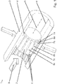
- the piston 2 thereby has a smaller outer diameter than the inner diameter of the formed as a sleeve thrust bearing 3. Contrary to the sliding direction 9, the piston has a larger outer diameter than the inner diameter of the thrust bearing 3 due to the conical shape. In this way, a targeted deformation of the thrust bearing 3 can be achieved by the sliding unit 2.
- FIG. 2 pushes the piston 2 when sliding along the sliding path a in the direction of sliding 9, the sleeve of the thrust bearing 3 to the outside and thereby ensures a defined predeterminable displacement resistance between the thrust bearing 3 and the sliding unit 2.
- the through the narrower sleeve 3 on the Piston 2 exerted force F also serves the exact specification of the displacement resistance of the along the glide path a.
- the sliding unit 2 is pressed in the sliding direction 9 in the counter-bearing 3.
- a force-displacement diagram is recorded, which provides information about the displacement resistance on the remaining glide path a.
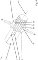
- the FIG. 4 shows another axial resistance sliding bearing 1.
- the abutment 3 is formed here as a piston and the sliding unit 2 as the abutment 3 surrounding sleeve.
- the sleeve of the sliding unit 2 is shown cut away.
- the bearing axis 5 of the resistance sliding bearing 1 is formed, which sets the direction of the sliding a.
- the sliding unit 2 slides along the sliding path a in the sliding direction 9 along the counter-bearing 3.
- two components, not shown, which are connected to one with the sliding unit 2 and the other with the anvil 3 are defined by the resistance sliding bearing 1 defined to each other.
- a defined displacement resistance between the sliding unit 2 and the anvil 3 is crucial.
- the displacement resistance can be given for this purpose essentially by the static friction resistance and the Gleitreibungswiderstand between the sliding unit 2 and the thrust bearing 3.
- a static friction which essentially corresponds to the Gleitreibungswiderstand between the sliding unit 2 and the anvil 3
- a defined displacement resistance between the sliding unit 2 and 3 abutment can be specified.
Landscapes
- Engineering & Computer Science (AREA)
- General Engineering & Computer Science (AREA)
- Mechanical Engineering (AREA)
- Architecture (AREA)
- Civil Engineering (AREA)
- Structural Engineering (AREA)
- Ocean & Marine Engineering (AREA)
- Sliding-Contact Bearings (AREA)
Priority Applications (1)
| Application Number | Priority Date | Filing Date | Title |
|---|---|---|---|
| EP17167808.9A EP3396182A1 (fr) | 2017-04-24 | 2017-04-24 | Palier lisse à résistance axiale au glissement |
Applications Claiming Priority (1)
| Application Number | Priority Date | Filing Date | Title |
|---|---|---|---|
| EP17167808.9A EP3396182A1 (fr) | 2017-04-24 | 2017-04-24 | Palier lisse à résistance axiale au glissement |
Publications (1)
| Publication Number | Publication Date |
|---|---|
| EP3396182A1 true EP3396182A1 (fr) | 2018-10-31 |
Family
ID=58640696
Family Applications (1)
| Application Number | Title | Priority Date | Filing Date |
|---|---|---|---|
| EP17167808.9A Withdrawn EP3396182A1 (fr) | 2017-04-24 | 2017-04-24 | Palier lisse à résistance axiale au glissement |
Country Status (1)
| Country | Link |
|---|---|
| EP (1) | EP3396182A1 (fr) |
Citations (5)
| Publication number | Priority date | Publication date | Assignee | Title |
|---|---|---|---|---|
| US3486396A (en) * | 1967-01-20 | 1969-12-30 | Honda Gijutsu Kenkyusho Kk | Steering apparatus for motor car |
| US3504568A (en) * | 1968-01-26 | 1970-04-07 | Fuji Jyukogyo Kk | Impact-absorbing steering shaft |
| US3899047A (en) * | 1972-04-19 | 1975-08-12 | Nissan Motor | Impact absorbing device and motor vehicle body structure incorporating the same |
| WO2006027094A1 (fr) * | 2004-09-07 | 2006-03-16 | Volkswagen Aktiengesellschaft | Systeme de tube |
| US7288029B1 (en) * | 2005-01-19 | 2007-10-30 | Gkn Driveline North America, Inc. | Propshaft with crash-worthiness |
-
2017
- 2017-04-24 EP EP17167808.9A patent/EP3396182A1/fr not_active Withdrawn
Patent Citations (5)
| Publication number | Priority date | Publication date | Assignee | Title |
|---|---|---|---|---|
| US3486396A (en) * | 1967-01-20 | 1969-12-30 | Honda Gijutsu Kenkyusho Kk | Steering apparatus for motor car |
| US3504568A (en) * | 1968-01-26 | 1970-04-07 | Fuji Jyukogyo Kk | Impact-absorbing steering shaft |
| US3899047A (en) * | 1972-04-19 | 1975-08-12 | Nissan Motor | Impact absorbing device and motor vehicle body structure incorporating the same |
| WO2006027094A1 (fr) * | 2004-09-07 | 2006-03-16 | Volkswagen Aktiengesellschaft | Systeme de tube |
| US7288029B1 (en) * | 2005-01-19 | 2007-10-30 | Gkn Driveline North America, Inc. | Propshaft with crash-worthiness |
Similar Documents
| Publication | Publication Date | Title |
|---|---|---|
| DE102013216524B3 (de) | Druckmessumformer mit verdrehbarer Gehäusehülse | |
| DE102012113053A1 (de) | Verbindungsmittel mit Formgedächtnis | |
| DE112010005816T5 (de) | Bremshebel für eine Bremse eines Kraftfahrzeugs | |
| DE102013011469A1 (de) | Führungseinrichtung für eine Schwimmsattel-Scheibenbremse | |
| DE4409492B4 (de) | Schaltarretierung | |
| EP3396182A1 (fr) | Palier lisse à résistance axiale au glissement | |
| AT505294B1 (de) | Verfahren zum druckdichten verschliessen einer bohrung, sowie druckgehäuse | |
| DE102006014331B4 (de) | Doppelohr-Hydraulikstossdämpfer | |
| DE102014218303A1 (de) | Lenkgetriebe | |
| DE102019205032B4 (de) | Hydraulikkomponente mit einem Komponentengehäuse und einem Anschlussblock | |
| DE2910350C2 (de) | Kolbenstangenführung und -abdichtung, insbesondere für Stoßdämpfer von Kraftfahrzeugen | |
| DE102009007847A1 (de) | Gleitlagerschale | |
| DE9300199U1 (de) | Betätigungsseil für insbesondere Seilzüge | |
| DE102014220337A1 (de) | Verfahren zur Herstellung eines Verbindungselements sowie Verbindungselement und CFK-Bauteil mit einem derartigen Verbindungselement | |
| EP3499096A1 (fr) | Conception d'anneau d'étanchéité sans friction sensible à la pression | |
| DE102005009213B4 (de) | Hydraulischer Schwingungsdämpfer mit ausknicksicherer Zuganschlagfeder | |
| DE10137296B4 (de) | Halteelement zur Festlegung eines Maschinenteils | |
| DE102006061126A1 (de) | Schaltgabeleinrichtung | |
| DE102015212860A1 (de) | Kolben-Vorrichtung, Verfahren zum Herstellen einer derartigen Kolben-Vorrichtung sowie Kolben-Zylinder-Einheit mit einer derartigen Kolben-Vorrichtung | |
| DE2051981A1 (de) | Dichtung mit induzierter Elastizität | |
| EP1995574B1 (fr) | Cellule de pesage | |
| DE102020215509A1 (de) | Aggregat mit einem axial betätigbaren Kolben | |
| DE102013103485A1 (de) | Verfahren zur Herstellung eines stangenförmigen Bauteils | |
| DE4111542C2 (de) | Mehrgleitflächenlager | |
| DE102015210909B3 (de) | Kolben-Zylinder-Anordnung und hydraulisches Kupplungsbetätigungssystem |
Legal Events
| Date | Code | Title | Description |
|---|---|---|---|
| PUAI | Public reference made under article 153(3) epc to a published international application that has entered the european phase |
Free format text: ORIGINAL CODE: 0009012 |
|
| AK | Designated contracting states |
Kind code of ref document: A1 Designated state(s): AL AT BE BG CH CY CZ DE DK EE ES FI FR GB GR HR HU IE IS IT LI LT LU LV MC MK MT NL NO PL PT RO RS SE SI SK SM TR |
|
| AX | Request for extension of the european patent |
Extension state: BA ME |
|
| RAP1 | Party data changed (applicant data changed or rights of an application transferred) |
Owner name: BOCHUMER EISENHUETTE GMBH & CO. KG |
|
| 17P | Request for examination filed |
Effective date: 20190430 |
|
| RBV | Designated contracting states (corrected) |
Designated state(s): AL AT BE BG CH CY CZ DE DK EE ES FI FR GB GR HR HU IE IS IT LI LT LU LV MC MK MT NL NO PL PT RO RS SE SI SK SM TR |
|
| 17Q | First examination report despatched |
Effective date: 20191018 |
|
| STAA | Information on the status of an ep patent application or granted ep patent |
Free format text: STATUS: THE APPLICATION IS DEEMED TO BE WITHDRAWN |
|
| 18D | Application deemed to be withdrawn |
Effective date: 20200229 |