EP3396234B1 - Dispositif d'éclairage - Google Patents
Dispositif d'éclairage Download PDFInfo
- Publication number
- EP3396234B1 EP3396234B1 EP18153190.6A EP18153190A EP3396234B1 EP 3396234 B1 EP3396234 B1 EP 3396234B1 EP 18153190 A EP18153190 A EP 18153190A EP 3396234 B1 EP3396234 B1 EP 3396234B1
- Authority
- EP
- European Patent Office
- Prior art keywords
- housing
- luminaire
- lighting unit
- power supply
- fact
- Prior art date
- Legal status (The legal status is an assumption and is not a legal conclusion. Google has not performed a legal analysis and makes no representation as to the accuracy of the status listed.)
- Active
Links
Images

Classifications
-
- F—MECHANICAL ENGINEERING; LIGHTING; HEATING; WEAPONS; BLASTING
- F21—LIGHTING
- F21V—FUNCTIONAL FEATURES OR DETAILS OF LIGHTING DEVICES OR SYSTEMS THEREOF; STRUCTURAL COMBINATIONS OF LIGHTING DEVICES WITH OTHER ARTICLES, NOT OTHERWISE PROVIDED FOR
- F21V21/00—Supporting, suspending, or attaching arrangements for lighting devices; Hand grips
- F21V21/14—Adjustable mountings
- F21V21/30—Pivoted housings or frames
-
- F—MECHANICAL ENGINEERING; LIGHTING; HEATING; WEAPONS; BLASTING
- F21—LIGHTING
- F21S—NON-PORTABLE LIGHTING DEVICES; SYSTEMS THEREOF; VEHICLE LIGHTING DEVICES SPECIALLY ADAPTED FOR VEHICLE EXTERIORS
- F21S8/00—Lighting devices intended for fixed installation
- F21S8/02—Lighting devices intended for fixed installation of recess-mounted type, e.g. downlighters
- F21S8/026—Lighting devices intended for fixed installation of recess-mounted type, e.g. downlighters intended to be recessed in a ceiling or like overhead structure, e.g. suspended ceiling
-
- H—ELECTRICITY
- H02—GENERATION; CONVERSION OR DISTRIBUTION OF ELECTRIC POWER
- H02G—INSTALLATION OF ELECTRIC CABLES OR LINES, OR OF COMBINED OPTICAL AND ELECTRIC CABLES OR LINES
- H02G3/00—Installations of electric cables or lines or protective tubing therefor in or on buildings, equivalent structures or vehicles
- H02G3/02—Details
- H02G3/08—Distribution boxes; Connection or junction boxes
- H02G3/18—Distribution boxes; Connection or junction boxes providing line outlets
- H02G3/20—Ceiling roses or other lighting sets
-
- F—MECHANICAL ENGINEERING; LIGHTING; HEATING; WEAPONS; BLASTING
- F21—LIGHTING
- F21Y—INDEXING SCHEME ASSOCIATED WITH SUBCLASSES F21K, F21L, F21S and F21V, RELATING TO THE FORM OR THE KIND OF THE LIGHT SOURCES OR OF THE COLOUR OF THE LIGHT EMITTED
- F21Y2115/00—Light-generating elements of semiconductor light sources
- F21Y2115/10—Light-emitting diodes [LED]
Definitions
- the present invention is based on a designed according to the preamble of the main claim lighting device, which is provided for accommodation in conventional flush-mounted installation boxes.
- Such lighting devices are usually intended to provide inside and / or outside of buildings for the targeted illumination of their environment, for the illumination of directly in their environment befindlichem objects and / or for an orientation, ambience or signaling lighting. If such lighting devices used, for example, for installation in ceilings, walls or building facades, a compact design with robust design is often necessary for easy installation. It is increasingly important that such lighting devices have an attractive design and allow the user a tunable to the application light output with a compact design.
- a lighting device intended for installation in conventional flush-mounted boxes, is by the DE 20 2005 018 867 U1 known.
- This lighting device is provided for accommodation in conventional flush-mounted installation boxes, wherein the lighting device has a power supply unit arranged in a first housing and a second housing provided with a support ring for accommodating a lamp module.
- the lighting module is electrically connected to the power supply in connection with the power supply, which in turn is connected to the electrical installation system of a building.
- the luminaire module of this illumination device has at least one LED.
- the lighting device has a in a first housing arranged power supply and to be provided with a carrier, provided for housing a light module second housing, wherein the lighting module for power supply is electrically connected to the power supply in connection, which power supply in turn is connectable to the electrical installation system of a building and wherein the lighting module is a spherical Luminaire, which is guided pivotably on a bearing plate fixed to the second housing.
- a lighting device is already provided because of their considerable dimensions only for surface mounting on a building wall or building ceiling. For a flush mounting such lighting devices are not suitable and can not be integrated particularly well in the design of existing cover programs.
- This LED downlight contains a unit with at least one LED and a power supply and fasteners for mounting the unit in a commercial electrical installation box, especially in a flush box.
- the ball lamp comprises a luminaire housing, in the interior of which a luminaire body, which can be pivoted about a pivoting angle in a predetermined three-dimensional area, is provided with a luminous means receptacle for at least one luminous means.
- a luminous means receptacle for at least one luminous means.
- an auxiliary lens is arranged, which together with the luminaire body forms a spherical or spherical cap-shaped outer surface.
- the luminaire housing comprises at least one support for the attachment lens attached to the luminaire body and the luminaire body.
- suspension elements which press the lamp body and attached thereto additional lens resiliently against the at least one support.
- the suspension elements abut at maximum pivoting of the lamp body stops, which is limited by the stops of the pivot angle so that in each position only the auxiliary lens, but not the lamp body protrudes from the lamp housing, whereby the lamp for all adjustable tilt angle has an unchanged appearance ,
- a car reading light which includes a lamp, a light source, a light main body and a spring.
- the cover of the luminaire has an outer surface formed of a part of a spherical surface.
- the body of the lamp is formed of a metal and has a back surface formed of another part of the surface of the ball.
- the light main body includes a receiving / guiding portion that supports the outer surface.
- the receiving / guiding section carries the lamp so that the lamp is rotatable, thereby allowing the direction of the light emitted from the lamp to be changed.
- the lamp is fitted into the lamp main body, in which the back surface is pressed by means of the spring.
- Either the receiving / guiding portion or the cover is formed of a metal or plastic to avoid problems due to sliding friction in long-term use.
- the illuminated switch has a switching mechanism, a power supply, and a printed circuit carrying at least one lighting component on its front side.
- a switchgear fixture comprising a seal.
- a lighting device has become known.
- a plurality of LED lamps are arranged on a printed circuit board, which can be connected via this to an installation system of a building.
- This lighting device may for example be constructed so that the housing is formed in a closed design made of plastic, wherein the lighting means and the associated power supply are completely absorbed by this and connectable via connections to the mains.
- the design is chosen so that the lighting device can be installed in standard flush-mounted boxes, cable ducts and so on. By using a system shutter, the lighting device can be adapted to the design of an existing cover program.
- the present invention is therefore an object of the invention to provide a lighting device, which can be connected with the use of common installation components (support ring, flush-mounted box) with a particularly compact design in a simple and cost-effective manner to the installation system of a building and which also user-side on particularly simple Can be tuned in terms of light output for specific applications.
- the luminaire housing provided with the luminous means or the luminous means can be fastened to the second housing without tools so that it can be pivoted and / or rotated as desired by the user in order to tune the light output to be able to carry out certain applications.
- This can be realized in a particularly advantageous manner if the luminaire module is provided with a luminaire which has a spherical luminaire housing.
- the compact luminaire housing can be particularly well integrated into the design of existing cover programs of a manufacturer of installation devices.
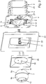
- the luminaire module is electrically connected to the power supply 3 in connection with the power supply, which in turn can be connected to the electrical installation system of a building (not shown for the sake of simplicity).
- the luminaire module has a spherical luminaire 7, which is guided pivotably and / or rotatably in a bearing shell 8 fixed to the second housing 5.
- two pins 10 are present, which cooperate for pivoting and / or rotation limitation, each with a present in the bearing shell 8 control geometry 11.
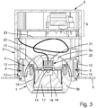
- the lamp module consists of the spherical lamp 7, provided for supporting the spherical lamp 7, consisting of metal bearing shell 8 and two for securing removal of the spherical lamp 7 serving clip elements 6, which on the one hand clipend with the support ring also made of metal. 4 come into operative connection and which on the other hand with its bearing surface 12 slidably depending on the first lamp housing part 9a and / or the second Luminaire housing part 9b of the spherical lamp 7 cooperate.
- the holding effect or removal protection of the two clip elements 6 is generated because they come with their bearing surfaces 12 on the user side above the largest diameter range of the lamp housing 9a, 9b on the spherical lamp 7 to the plant.
- the support ring 4 made of metal is in operative connection by means of a plurality of clip connections 13 both with the second housing part 5 and with the bearing shell 8 made of metal.
- Such an operative connection or the bearing surfaces created thereby between the support ring 4 and the bearing shell 8 ensure that the heat generated by the light source 14 can be effectively released to the environment.
- the first lamp housing part 9a is made of metal, a good heat transfer path is created, which, starting from the light source 14, via the metal first light housing 9a and the metal bearing shell 8 leads to the large, also made of metal support ring 4. Ultimately, the heat is effectively released to the environment over the relatively large area of the support ring 4.
- a circuit board 15 which is equipped with the LED designed as a light bulb 14.
- a light box 16 surrounding the light source 14 and a mounted on the light box 16 light guide 17 are present.
- the optical waveguide 17 is provided with a light emitting area 18 facing it for coupling the light emitted by the illuminant 14, and on the other hand has a light decoupling area assigned to the second housing part 9b on the user side.
- the light extraction region is associated with an eye-like light exit region 19 of the second luminaire housing part 9b.
- the first luminaire housing part 9a is provided with a connection region 20 enabling the electrical connection to the power supply 3.
- the connection region 20 is provided for contacting with a plug 21, to the several, with the power supply 3 in connection standing electrical lines 22 are connected.
- the electrical lines 22 have a loop-like installation within the interior of the second housing 5.
- the movement reserve is necessary to enable the user to unhindered pivoting and / or rotation of the spherical lamp 7. Also, this movement reserve is necessary so that the user can make a replacement of the spherical lamp 7 in a particularly simple manner, if necessary.
- first housing 2 is taken from the installation system of the building normal mains voltage in the amount of about 220 volts.
- second housing 5 is only the so-called "SELV voltage" (in the present case about 5 volts) to allow the user a safe handling of the spherical lamp 7.
- the design central piece 25 has a plurality of fastening springs 26 which cooperate with correspondingly executed fastening recesses 27 of the support ring 4.
- a lighting device provided for accommodation in conventional flush-mounted installation boxes 1 realized.
- a lighting device designed in this way can be connected to the installation system of a building in a simple and cost-effective manner when using conventional installation components (support ring, flush-mounted box) in a particularly compact design.
- the user can vote in a particularly comfortable way, the light output to specific applications by this the light 7 by simple handles as needed pivoted and / or twisted.
Landscapes
- Engineering & Computer Science (AREA)
- General Engineering & Computer Science (AREA)
- Architecture (AREA)
- Civil Engineering (AREA)
- Structural Engineering (AREA)
- Arrangement Of Elements, Cooling, Sealing, Or The Like Of Lighting Devices (AREA)
- Non-Portable Lighting Devices Or Systems Thereof (AREA)
Claims (9)
- Dispositif d'éclairage prévu pour être logé dans des boîtes d'installation encastrées conventionnelles (1), dans lequel le dispositif d'éclairage comporte une unité d'alimentation électrique (3) disposée dans un premier boîtier (2) et un second boîtier (5) muni d'une bague de support métallique (4) et prévu pour recevoir un module d'éclairage, le module d'éclairage étant relié électriquement à l'unité d'alimentation (3) par une liaison conductrice pour fournir l'énergie, laquelle unité d'alimentation (3), à son tour, peut être reliée au système d'installation électrique d'un bâtiment, le module de luminaire comportant un luminaire sphérique (7) qui est guidé de manière pivotante et/ou rotative dans un coussinet métallique (8) fixé au deuxième boîtier (5), au moins deux broches (10) étant présentes sur le boîtier en deux parties (9a, 9b) du luminaire sphérique (7), qui coopèrent chacune avec au moins une géométrie de commande (11) présente dans le coussinet (8) pour limiter le pivotement et/ou la rotation, et dans lequel deux éléments de serrage (6) sont prévus sur le coussinet (8) pour maintenir le boîtier de luminaire (9a, 9b), lesquels éléments de serrage (6) d'une part sont liés à la bague support (4) par clip et d'autre part leur surface support (12) coopère par glissement avec la première partie du boîtier de luminaire (9a) et/ou la seconde partie du boîtier de lumière (9b) du luminaire sphérique (7) qui se trouve sur le côté du boîtier de luminaire (9a, 9b) qui se trouve au-delà de la plus grande plage de diamètre du boîtier de luminaire (9a, 9b) et qui est opposé à l'intérieur du dispositif d'éclairage, et dans lequel une plaquette à circuit imprimé (15) équipée d'au moins un moyen d'éclairage (14) et une boîte à lumière (16) munie d'au moins un corps guide lumière (17) sont placées à l'intérieur du boîtier de luminaire à deux pièces (9a, 9b).
- Dispositif d'éclairage selon la revendication 1, caractérisé en ce que la première partie (9a) du boîtier de luminaire en deux parties faisant face à l'unité d'alimentation (3) est muni d'un raccordement (20) permettant la connexion électrique avec l'unité d'alimentation (3).
- Dispositif d'éclairage selon la revendication 2, caractérisé en ce que le raccordement (20) est disposé comme connexion enfichable.
- Dispositif d'éclairage selon la revendication 2, caractérisé en ce que le raccordement (20) est disposé comme connexion à bornes.
- Dispositif d'éclairage selon l'une des revendications 1 à 4, caractérisé en ce que la deuxième partie (9b) du boîtier de luminaire en deux parties, qui, du côté utilisateur, est guidée vers l'extérieur, est munie d'une zone de sortie de lumière (19) en forme d'oeil.
- Dispositif d'éclairage selon l'une des revendications 1 à 5, caractérisé en ce qu'une base de séparation unique (23) est prévue pour séparer le premier boîtier (2) du second boîtier (5).
- Dispositif d'éclairage selon l'une des revendications 1 à 6, caractérisé en ce qu'une pluralité de conducteurs électriques (22) sont prévus pour la connexion électrique entre l'unité d'alimentation (3) et le luminaire sphérique (7).
- Dispositif d'éclairage selon la revendication 7, caractérisé en ce que les conducteurs électriques (22) sont placés en forme de boucles à l'intérieur du deuxième boîtier (5) pour former une réserve de mouvement.
- Dispositif d'éclairage selon l'une des revendications 1 à 8, caractérisé en ce qu'un cadre dècoratif (24) est prévu pour réaliser une conception élégante côté utilisateur, lequel cadre décoratif peut être fixé à l'anneau de support (4) au moyen d'une pièce centrale décoratif (25) permettant le passage du boîtier de luminaire (9a, 9b).
Applications Claiming Priority (1)
| Application Number | Priority Date | Filing Date | Title |
|---|---|---|---|
| DE102017109135.1A DE102017109135B3 (de) | 2017-04-28 | 2017-04-28 | Beleuchtungseinrichtung für eine Unterputzinstallationsdose mit einer verschwenkbaren und/oder verdrehbaren kugelförmigen Leuchte, die durch zwei Clipselemente befestigt ist |
Publications (2)
| Publication Number | Publication Date |
|---|---|
| EP3396234A1 EP3396234A1 (fr) | 2018-10-31 |
| EP3396234B1 true EP3396234B1 (fr) | 2019-09-18 |
Family
ID=61027492
Family Applications (1)
| Application Number | Title | Priority Date | Filing Date |
|---|---|---|---|
| EP18153190.6A Active EP3396234B1 (fr) | 2017-04-28 | 2018-01-24 | Dispositif d'éclairage |
Country Status (2)
| Country | Link |
|---|---|
| EP (1) | EP3396234B1 (fr) |
| DE (1) | DE102017109135B3 (fr) |
Families Citing this family (1)
| Publication number | Priority date | Publication date | Assignee | Title |
|---|---|---|---|---|
| US9752739B2 (en) * | 2011-08-29 | 2017-09-05 | Hubbell Incorporated | Emergency lighting assembly having heat conducting member |
Family Cites Families (8)
| Publication number | Priority date | Publication date | Assignee | Title |
|---|---|---|---|---|
| US2649535A (en) | 1947-07-05 | 1953-08-18 | Abraham H Feder | Recessed lighting fixture with adjustable spotlight |
| DE19919080A1 (de) | 1999-04-27 | 2000-11-02 | Insta Elektro Gmbh & Co Kg | Beleuchtungseinrichtung |
| DE10322177A1 (de) * | 2003-05-16 | 2004-12-02 | Ludwig Leuchten Kg | LED-Einbauleuchte |
| DE202005018867U1 (de) | 2005-12-02 | 2006-01-26 | Wilhelm Koch Gmbh | Bausatz einer Wandleuchte |
| DE202007006742U1 (de) | 2007-05-10 | 2007-07-19 | Wilhelm Koch Gmbh | Leuchte |
| JP5332770B2 (ja) * | 2008-04-18 | 2013-11-06 | 東芝ライテック株式会社 | 照明器具 |
| AT511172B1 (de) | 2011-02-25 | 2012-12-15 | Hierzer Andreas | Kugelleuchte |
| FR3013160B1 (fr) * | 2013-11-13 | 2015-11-27 | Legrand France | Appareillage electrique d’eclairage a monter dans une boite electrique |
-
2017
- 2017-04-28 DE DE102017109135.1A patent/DE102017109135B3/de not_active Expired - Fee Related
-
2018
- 2018-01-24 EP EP18153190.6A patent/EP3396234B1/fr active Active
Non-Patent Citations (1)
| Title |
|---|
| None * |
Also Published As
| Publication number | Publication date |
|---|---|
| EP3396234A1 (fr) | 2018-10-31 |
| DE102017109135B3 (de) | 2018-05-24 |
Similar Documents
| Publication | Publication Date | Title |
|---|---|---|
| EP2093476B1 (fr) | Profilé de lampes | |
| DE202011051094U1 (de) | Leuchteneinheit für eine Leuchte, sowie Leuchte | |
| EP1983620B1 (fr) | Prise électrique dotée d'un éclairage d'orientation | |
| DE102008064454A1 (de) | Elektrisches Installationsgerät | |
| EP3527886B1 (fr) | Dispositif comprenant un appareil d'instalation électrique/ électronique et un luminiare électrique | |
| EP3114400B1 (fr) | Luminaire ou ensemble lumineux comprenant un élément support allongé et un module lumineux fixé de manière libérable | |
| WO2015132226A1 (fr) | Luminaire comprenant des moyens lumineux pour une émission de lumière directe et indirecte | |
| DE102011054266B3 (de) | Elektrische Schutzkontaktsteckdose | |
| DE202017103604U1 (de) | Beleuchtungseinrichtung | |
| EP2363634B1 (fr) | Lampe à DEL encastrée, notamment plafonnière | |
| EP3527887B1 (fr) | Dispositif comprenant un appareil d'installation électrique / électronique et un luminaire électrique. | |
| DE102017109135B3 (de) | Beleuchtungseinrichtung für eine Unterputzinstallationsdose mit einer verschwenkbaren und/oder verdrehbaren kugelförmigen Leuchte, die durch zwei Clipselemente befestigt ist | |
| EP2187485B1 (fr) | Prise électrique | |
| DE29711379U1 (de) | Beleuchtungsanlage mit Dimmer | |
| EP2138763B1 (fr) | Projecteur et système rail conducteur pour un tel projecteur | |
| DE102016104426A1 (de) | Modul für modulare Außenleuchte | |
| DE19541665C1 (de) | Bewegungsmelder und Beleuchtungsanlage mit Bewegungsmelder | |
| DE202016103954U1 (de) | Leuchte mit zwei Gehäuseteilen | |
| EP3527872B1 (fr) | Lampe électrique | |
| DE102018103375B3 (de) | Elektrische Leuchte | |
| DE202015004198U1 (de) | Leuchtenbaldachin | |
| EP2208923B1 (fr) | Eclairage | |
| DE102011016763B3 (de) | Beleuchtungseinrichtung, Leuchtkörperhalter und Leuchtkörper dafür | |
| DE20013280U1 (de) | Hinweisleuchte | |
| EP0787944A1 (fr) | Support de lampe à encombrement réduit |
Legal Events
| Date | Code | Title | Description |
|---|---|---|---|
| PUAI | Public reference made under article 153(3) epc to a published international application that has entered the european phase |
Free format text: ORIGINAL CODE: 0009012 |
|
| STAA | Information on the status of an ep patent application or granted ep patent |
Free format text: STATUS: THE APPLICATION HAS BEEN PUBLISHED |
|
| AK | Designated contracting states |
Kind code of ref document: A1 Designated state(s): AL AT BE BG CH CY CZ DE DK EE ES FI FR GB GR HR HU IE IS IT LI LT LU LV MC MK MT NL NO PL PT RO RS SE SI SK SM TR |
|
| AX | Request for extension of the european patent |
Extension state: BA ME |
|
| STAA | Information on the status of an ep patent application or granted ep patent |
Free format text: STATUS: REQUEST FOR EXAMINATION WAS MADE |
|
| 17P | Request for examination filed |
Effective date: 20181109 |
|
| RBV | Designated contracting states (corrected) |
Designated state(s): AL AT BE BG CH CY CZ DE DK EE ES FI FR GB GR HR HU IE IS IT LI LT LU LV MC MK MT NL NO PL PT RO RS SE SI SK SM TR |
|
| STAA | Information on the status of an ep patent application or granted ep patent |
Free format text: STATUS: EXAMINATION IS IN PROGRESS |
|
| 17Q | First examination report despatched |
Effective date: 20190329 |
|
| GRAP | Despatch of communication of intention to grant a patent |
Free format text: ORIGINAL CODE: EPIDOSNIGR1 |
|
| STAA | Information on the status of an ep patent application or granted ep patent |
Free format text: STATUS: GRANT OF PATENT IS INTENDED |
|
| RIC1 | Information provided on ipc code assigned before grant |
Ipc: F21V 21/30 20060101ALI20190613BHEP Ipc: F21Y 115/10 20160101ALN20190613BHEP Ipc: F21S 8/02 20060101AFI20190613BHEP |
|
| GRAS | Grant fee paid |
Free format text: ORIGINAL CODE: EPIDOSNIGR3 |
|
| INTG | Intention to grant announced |
Effective date: 20190709 |
|
| GRAA | (expected) grant |
Free format text: ORIGINAL CODE: 0009210 |
|
| STAA | Information on the status of an ep patent application or granted ep patent |
Free format text: STATUS: THE PATENT HAS BEEN GRANTED |
|
| AK | Designated contracting states |
Kind code of ref document: B1 Designated state(s): AL AT BE BG CH CY CZ DE DK EE ES FI FR GB GR HR HU IE IS IT LI LT LU LV MC MK MT NL NO PL PT RO RS SE SI SK SM TR |
|
| REG | Reference to a national code |
Ref country code: GB Ref legal event code: FG4D Free format text: NOT ENGLISH |
|
| REG | Reference to a national code |
Ref country code: CH Ref legal event code: EP |
|
| REG | Reference to a national code |
Ref country code: DE Ref legal event code: R096 Ref document number: 502018000217 Country of ref document: DE |
|
| REG | Reference to a national code |
Ref country code: AT Ref legal event code: REF Ref document number: 1181758 Country of ref document: AT Kind code of ref document: T Effective date: 20191015 |
|
| REG | Reference to a national code |
Ref country code: IE Ref legal event code: FG4D Free format text: LANGUAGE OF EP DOCUMENT: GERMAN |
|
| REG | Reference to a national code |
Ref country code: SE Ref legal event code: TRGR |
|
| REG | Reference to a national code |
Ref country code: NL Ref legal event code: FP |
|
| PG25 | Lapsed in a contracting state [announced via postgrant information from national office to epo] |
Ref country code: HR Free format text: LAPSE BECAUSE OF FAILURE TO SUBMIT A TRANSLATION OF THE DESCRIPTION OR TO PAY THE FEE WITHIN THE PRESCRIBED TIME-LIMIT Effective date: 20190918 Ref country code: BG Free format text: LAPSE BECAUSE OF FAILURE TO SUBMIT A TRANSLATION OF THE DESCRIPTION OR TO PAY THE FEE WITHIN THE PRESCRIBED TIME-LIMIT Effective date: 20191218 Ref country code: LT Free format text: LAPSE BECAUSE OF FAILURE TO SUBMIT A TRANSLATION OF THE DESCRIPTION OR TO PAY THE FEE WITHIN THE PRESCRIBED TIME-LIMIT Effective date: 20190918 Ref country code: NO Free format text: LAPSE BECAUSE OF FAILURE TO SUBMIT A TRANSLATION OF THE DESCRIPTION OR TO PAY THE FEE WITHIN THE PRESCRIBED TIME-LIMIT Effective date: 20191218 Ref country code: FI Free format text: LAPSE BECAUSE OF FAILURE TO SUBMIT A TRANSLATION OF THE DESCRIPTION OR TO PAY THE FEE WITHIN THE PRESCRIBED TIME-LIMIT Effective date: 20190918 |
|
| REG | Reference to a national code |
Ref country code: LT Ref legal event code: MG4D |
|
| PG25 | Lapsed in a contracting state [announced via postgrant information from national office to epo] |
Ref country code: GR Free format text: LAPSE BECAUSE OF FAILURE TO SUBMIT A TRANSLATION OF THE DESCRIPTION OR TO PAY THE FEE WITHIN THE PRESCRIBED TIME-LIMIT Effective date: 20191219 Ref country code: RS Free format text: LAPSE BECAUSE OF FAILURE TO SUBMIT A TRANSLATION OF THE DESCRIPTION OR TO PAY THE FEE WITHIN THE PRESCRIBED TIME-LIMIT Effective date: 20190918 Ref country code: AL Free format text: LAPSE BECAUSE OF FAILURE TO SUBMIT A TRANSLATION OF THE DESCRIPTION OR TO PAY THE FEE WITHIN THE PRESCRIBED TIME-LIMIT Effective date: 20190918 Ref country code: LV Free format text: LAPSE BECAUSE OF FAILURE TO SUBMIT A TRANSLATION OF THE DESCRIPTION OR TO PAY THE FEE WITHIN THE PRESCRIBED TIME-LIMIT Effective date: 20190918 |
|
| PG25 | Lapsed in a contracting state [announced via postgrant information from national office to epo] |
Ref country code: ES Free format text: LAPSE BECAUSE OF FAILURE TO SUBMIT A TRANSLATION OF THE DESCRIPTION OR TO PAY THE FEE WITHIN THE PRESCRIBED TIME-LIMIT Effective date: 20190918 Ref country code: EE Free format text: LAPSE BECAUSE OF FAILURE TO SUBMIT A TRANSLATION OF THE DESCRIPTION OR TO PAY THE FEE WITHIN THE PRESCRIBED TIME-LIMIT Effective date: 20190918 Ref country code: PT Free format text: LAPSE BECAUSE OF FAILURE TO SUBMIT A TRANSLATION OF THE DESCRIPTION OR TO PAY THE FEE WITHIN THE PRESCRIBED TIME-LIMIT Effective date: 20200120 Ref country code: RO Free format text: LAPSE BECAUSE OF FAILURE TO SUBMIT A TRANSLATION OF THE DESCRIPTION OR TO PAY THE FEE WITHIN THE PRESCRIBED TIME-LIMIT Effective date: 20190918 Ref country code: PL Free format text: LAPSE BECAUSE OF FAILURE TO SUBMIT A TRANSLATION OF THE DESCRIPTION OR TO PAY THE FEE WITHIN THE PRESCRIBED TIME-LIMIT Effective date: 20190918 |
|
| PG25 | Lapsed in a contracting state [announced via postgrant information from national office to epo] |
Ref country code: IS Free format text: LAPSE BECAUSE OF FAILURE TO SUBMIT A TRANSLATION OF THE DESCRIPTION OR TO PAY THE FEE WITHIN THE PRESCRIBED TIME-LIMIT Effective date: 20200224 Ref country code: SK Free format text: LAPSE BECAUSE OF FAILURE TO SUBMIT A TRANSLATION OF THE DESCRIPTION OR TO PAY THE FEE WITHIN THE PRESCRIBED TIME-LIMIT Effective date: 20190918 Ref country code: CZ Free format text: LAPSE BECAUSE OF FAILURE TO SUBMIT A TRANSLATION OF THE DESCRIPTION OR TO PAY THE FEE WITHIN THE PRESCRIBED TIME-LIMIT Effective date: 20190918 Ref country code: SM Free format text: LAPSE BECAUSE OF FAILURE TO SUBMIT A TRANSLATION OF THE DESCRIPTION OR TO PAY THE FEE WITHIN THE PRESCRIBED TIME-LIMIT Effective date: 20190918 |
|
| REG | Reference to a national code |
Ref country code: DE Ref legal event code: R097 Ref document number: 502018000217 Country of ref document: DE |
|
| PLBE | No opposition filed within time limit |
Free format text: ORIGINAL CODE: 0009261 |
|
| STAA | Information on the status of an ep patent application or granted ep patent |
Free format text: STATUS: NO OPPOSITION FILED WITHIN TIME LIMIT |
|
| PG2D | Information on lapse in contracting state deleted |
Ref country code: IS |
|
| PG25 | Lapsed in a contracting state [announced via postgrant information from national office to epo] |
Ref country code: DK Free format text: LAPSE BECAUSE OF FAILURE TO SUBMIT A TRANSLATION OF THE DESCRIPTION OR TO PAY THE FEE WITHIN THE PRESCRIBED TIME-LIMIT Effective date: 20190918 Ref country code: IS Free format text: LAPSE BECAUSE OF FAILURE TO SUBMIT A TRANSLATION OF THE DESCRIPTION OR TO PAY THE FEE WITHIN THE PRESCRIBED TIME-LIMIT Effective date: 20200119 |
|
| 26N | No opposition filed |
Effective date: 20200619 |
|
| PG25 | Lapsed in a contracting state [announced via postgrant information from national office to epo] |
Ref country code: MC Free format text: LAPSE BECAUSE OF FAILURE TO SUBMIT A TRANSLATION OF THE DESCRIPTION OR TO PAY THE FEE WITHIN THE PRESCRIBED TIME-LIMIT Effective date: 20190918 |
|
| REG | Reference to a national code |
Ref country code: BE Ref legal event code: MM Effective date: 20200131 |
|
| PG25 | Lapsed in a contracting state [announced via postgrant information from national office to epo] |
Ref country code: LU Free format text: LAPSE BECAUSE OF NON-PAYMENT OF DUE FEES Effective date: 20200124 Ref country code: FR Free format text: LAPSE BECAUSE OF NON-PAYMENT OF DUE FEES Effective date: 20200131 |
|
| PG25 | Lapsed in a contracting state [announced via postgrant information from national office to epo] |
Ref country code: BE Free format text: LAPSE BECAUSE OF NON-PAYMENT OF DUE FEES Effective date: 20200131 |
|
| PG25 | Lapsed in a contracting state [announced via postgrant information from national office to epo] |
Ref country code: IE Free format text: LAPSE BECAUSE OF NON-PAYMENT OF DUE FEES Effective date: 20200124 |
|
| REG | Reference to a national code |
Ref country code: CH Ref legal event code: PL |
|
| PG25 | Lapsed in a contracting state [announced via postgrant information from national office to epo] |
Ref country code: LI Free format text: LAPSE BECAUSE OF NON-PAYMENT OF DUE FEES Effective date: 20210131 Ref country code: CH Free format text: LAPSE BECAUSE OF NON-PAYMENT OF DUE FEES Effective date: 20210131 |
|
| PG25 | Lapsed in a contracting state [announced via postgrant information from national office to epo] |
Ref country code: TR Free format text: LAPSE BECAUSE OF FAILURE TO SUBMIT A TRANSLATION OF THE DESCRIPTION OR TO PAY THE FEE WITHIN THE PRESCRIBED TIME-LIMIT Effective date: 20190918 Ref country code: MT Free format text: LAPSE BECAUSE OF FAILURE TO SUBMIT A TRANSLATION OF THE DESCRIPTION OR TO PAY THE FEE WITHIN THE PRESCRIBED TIME-LIMIT Effective date: 20190918 Ref country code: CY Free format text: LAPSE BECAUSE OF FAILURE TO SUBMIT A TRANSLATION OF THE DESCRIPTION OR TO PAY THE FEE WITHIN THE PRESCRIBED TIME-LIMIT Effective date: 20190918 |
|
| PG25 | Lapsed in a contracting state [announced via postgrant information from national office to epo] |
Ref country code: MK Free format text: LAPSE BECAUSE OF FAILURE TO SUBMIT A TRANSLATION OF THE DESCRIPTION OR TO PAY THE FEE WITHIN THE PRESCRIBED TIME-LIMIT Effective date: 20190918 |
|
| GBPC | Gb: european patent ceased through non-payment of renewal fee |
Effective date: 20220124 |
|
| PG25 | Lapsed in a contracting state [announced via postgrant information from national office to epo] |
Ref country code: GB Free format text: LAPSE BECAUSE OF NON-PAYMENT OF DUE FEES Effective date: 20220124 |
|
| PG25 | Lapsed in a contracting state [announced via postgrant information from national office to epo] |
Ref country code: SI Free format text: LAPSE BECAUSE OF FAILURE TO SUBMIT A TRANSLATION OF THE DESCRIPTION OR TO PAY THE FEE WITHIN THE PRESCRIBED TIME-LIMIT Effective date: 20190918 |
|
| PGFP | Annual fee paid to national office [announced via postgrant information from national office to epo] |
Ref country code: NL Payment date: 20260115 Year of fee payment: 9 |
|
| PGFP | Annual fee paid to national office [announced via postgrant information from national office to epo] |
Ref country code: SE Payment date: 20260115 Year of fee payment: 9 |
|
| PGFP | Annual fee paid to national office [announced via postgrant information from national office to epo] |
Ref country code: DE Payment date: 20251210 Year of fee payment: 9 |
|
| PGFP | Annual fee paid to national office [announced via postgrant information from national office to epo] |
Ref country code: AT Payment date: 20260128 Year of fee payment: 9 |
|
| PGFP | Annual fee paid to national office [announced via postgrant information from national office to epo] |
Ref country code: IT Payment date: 20251219 Year of fee payment: 9 |