EP3396242A1 - Projecteur de lumière ainsi que système de projecteur et meuble de travail pourvu d'un un tel projecteur de lumière - Google Patents
Projecteur de lumière ainsi que système de projecteur et meuble de travail pourvu d'un un tel projecteur de lumière Download PDFInfo
- Publication number
- EP3396242A1 EP3396242A1 EP18169707.9A EP18169707A EP3396242A1 EP 3396242 A1 EP3396242 A1 EP 3396242A1 EP 18169707 A EP18169707 A EP 18169707A EP 3396242 A1 EP3396242 A1 EP 3396242A1
- Authority
- EP
- European Patent Office
- Prior art keywords
- light
- light emitter
- emitter
- ceiling
- illuminant
- Prior art date
- Legal status (The legal status is an assumption and is not a legal conclusion. Google has not performed a legal analysis and makes no representation as to the accuracy of the status listed.)
- Granted
Links
Images


Classifications
-
- F—MECHANICAL ENGINEERING; LIGHTING; HEATING; WEAPONS; BLASTING
- F21—LIGHTING
- F21V—FUNCTIONAL FEATURES OR DETAILS OF LIGHTING DEVICES OR SYSTEMS THEREOF; STRUCTURAL COMBINATIONS OF LIGHTING DEVICES WITH OTHER ARTICLES, NOT OTHERWISE PROVIDED FOR
- F21V7/00—Reflectors for light sources
- F21V7/0008—Reflectors for light sources providing for indirect lighting
-
- F—MECHANICAL ENGINEERING; LIGHTING; HEATING; WEAPONS; BLASTING
- F21—LIGHTING
- F21S—NON-PORTABLE LIGHTING DEVICES; SYSTEMS THEREOF; VEHICLE LIGHTING DEVICES SPECIALLY ADAPTED FOR VEHICLE EXTERIORS
- F21S6/00—Lighting devices intended to be free-standing
- F21S6/002—Table lamps, e.g. for ambient lighting
-
- F—MECHANICAL ENGINEERING; LIGHTING; HEATING; WEAPONS; BLASTING
- F21—LIGHTING
- F21V—FUNCTIONAL FEATURES OR DETAILS OF LIGHTING DEVICES OR SYSTEMS THEREOF; STRUCTURAL COMBINATIONS OF LIGHTING DEVICES WITH OTHER ARTICLES, NOT OTHERWISE PROVIDED FOR
- F21V33/00—Structural combinations of lighting devices with other articles, not otherwise provided for
- F21V33/0004—Personal or domestic articles
- F21V33/0012—Furniture
-
- F—MECHANICAL ENGINEERING; LIGHTING; HEATING; WEAPONS; BLASTING
- F21—LIGHTING
- F21V—FUNCTIONAL FEATURES OR DETAILS OF LIGHTING DEVICES OR SYSTEMS THEREOF; STRUCTURAL COMBINATIONS OF LIGHTING DEVICES WITH OTHER ARTICLES, NOT OTHERWISE PROVIDED FOR
- F21V14/00—Controlling the distribution of the light emitted by adjustment of elements
- F21V14/08—Controlling the distribution of the light emitted by adjustment of elements by movement of the screens or filters
-
- F—MECHANICAL ENGINEERING; LIGHTING; HEATING; WEAPONS; BLASTING
- F21—LIGHTING
- F21V—FUNCTIONAL FEATURES OR DETAILS OF LIGHTING DEVICES OR SYSTEMS THEREOF; STRUCTURAL COMBINATIONS OF LIGHTING DEVICES WITH OTHER ARTICLES, NOT OTHERWISE PROVIDED FOR
- F21V23/00—Arrangement of electric circuit elements in or on lighting devices
- F21V23/04—Arrangement of electric circuit elements in or on lighting devices the elements being switches
- F21V23/0442—Arrangement of electric circuit elements in or on lighting devices the elements being switches activated by means of a sensor, e.g. motion or photodetectors
- F21V23/0464—Arrangement of electric circuit elements in or on lighting devices the elements being switches activated by means of a sensor, e.g. motion or photodetectors the sensor sensing the level of ambient illumination, e.g. dawn or dusk sensors
-
- F—MECHANICAL ENGINEERING; LIGHTING; HEATING; WEAPONS; BLASTING
- F21—LIGHTING
- F21V—FUNCTIONAL FEATURES OR DETAILS OF LIGHTING DEVICES OR SYSTEMS THEREOF; STRUCTURAL COMBINATIONS OF LIGHTING DEVICES WITH OTHER ARTICLES, NOT OTHERWISE PROVIDED FOR
- F21V23/00—Arrangement of electric circuit elements in or on lighting devices
- F21V23/04—Arrangement of electric circuit elements in or on lighting devices the elements being switches
- F21V23/0442—Arrangement of electric circuit elements in or on lighting devices the elements being switches activated by means of a sensor, e.g. motion or photodetectors
- F21V23/0471—Arrangement of electric circuit elements in or on lighting devices the elements being switches activated by means of a sensor, e.g. motion or photodetectors the sensor detecting the proximity, the presence or the movement of an object or a person
-
- F—MECHANICAL ENGINEERING; LIGHTING; HEATING; WEAPONS; BLASTING
- F21—LIGHTING
- F21W—INDEXING SCHEME ASSOCIATED WITH SUBCLASSES F21K, F21L, F21S and F21V, RELATING TO USES OR APPLICATIONS OF LIGHTING DEVICES OR SYSTEMS
- F21W2131/00—Use or application of lighting devices or systems not provided for in codes F21W2102/00-F21W2121/00
- F21W2131/40—Lighting for industrial, commercial, recreational or military use
- F21W2131/402—Lighting for industrial, commercial, recreational or military use for working places
-
- F—MECHANICAL ENGINEERING; LIGHTING; HEATING; WEAPONS; BLASTING
- F21—LIGHTING
- F21Y—INDEXING SCHEME ASSOCIATED WITH SUBCLASSES F21K, F21L, F21S and F21V, RELATING TO THE FORM OR THE KIND OF THE LIGHT SOURCES OR OF THE COLOUR OF THE LIGHT EMITTED
- F21Y2115/00—Light-generating elements of semiconductor light sources
- F21Y2115/10—Light-emitting diodes [LED]
Definitions
- the invention relates to a light emitter for generating a stream of visible light to a ceiling according to the preamble of claim 1 and a light emitter system with at least one such light emitter and a workstation furniture with such a light emitter.
- Such light emitters with a light source for producing artificial light in the visible range and an optical unit which is designed to shape the stream of visible light from the light generated by the light source can be used to irradiate walls and ceilings of rooms and on that way to light rooms.
- lamps are used in different adapted to the particular application embodiments. In this case, it is usually attempted to generate light distribution curves with the luminaires, which permit the best possible illumination for the intended use of the luminaires.
- luminaires with which rooms are illuminated indirectly.
- the luminaires emit light on ceilings and / or walls, thus creating lighting that is often perceived as pleasant.
- ceiling lights are also used, from which the workplaces are illuminated.
- ceiling lights are also used, from which the workplaces are illuminated.
- surface luminaires suspended on a room ceiling or installed in a room ceiling which specifically illuminate one or more workplaces.
- Such surface lights can be made relatively small and focused or larger and wider luminous.
- ceiling lights can be preferably illuminated by means of such ceiling lights and although such lights are relatively less disturbing, since they are not in places where other things are placed or people are staying, they are still relatively inflexible. Particularly in the case of regularly changing workplaces, for example in offices in which, for example, workstation groups are formed depending on the project, such ceiling lights are usually too inflexible since they have to be relocated, reoriented and configured. Also for the interior design such ceiling lights are often undesirable because they are typically fixed and therefore can not be redesigned.
- the object of the following invention is therefore to propose a system or components of a system which enable or enable a flexibly adaptable and configurable, specific illumination of workplaces in a room.
- a light emitter for generating a current of visible light to a ceiling comprises a light source for generating artificial light in the visible region and an optic.
- the optics are designed to shape the current of visible light from the light generated by the illuminant. It is further configured to define a light distribution curve of the light generated by the light source so that a luminaire object with a homogeneous luminance on the ceiling can be generated.
- the term "light distribution curve” is understood to mean a characterization of the light emitted by a luminaire, which can be represented in a graph.
- the light intensities of the luminaire are connected in their different directions of radiation to form a curve.
- the light distribution describes the spatial distribution of the light. Shape and symmetry of the light distribution characterize a depth or width and a symmetry of the radiation.
- luminaire object refers to a homogeneous closed light surface with a defined boundary or sharp edges.
- the luminaire object can have any shape on the ceiling. In particular, it can be formed round or polygonal on the ceiling and, for example, be designed as a spot.
- defined limit in this context means a decrease in the luminance at the ceiling to at most 10%, not more than 5% or almost 0%, which occurs over a maximum of about 30% of a diameter of the luminaire object or a central zone thereof.
- the center zone may be an area of the luminaire object which is not to be assigned to the defined boundary, ie to a border zone.
- the diameter may be an approximate diameter for non-circular shapes of the luminaire object.
- the term "sharp edge" in this context is understood to mean a decrease in luminance of at least about 20%, at least about 25%, at least about 30%, at least about 40% or at least about 50%, preferably to about 0% a maximum of about 10% of the diameter of the luminaire object or a center zone thereof takes place.
- luminance in the context of the invention refers to the brightness of the luminaire object on the ceiling, which acts as an extended, areal light source. It can provide information about the spatial and directional dependence of the light emitted by the luminaire object.
- homogeneous luminance refers to the fact that the brightness over the surface of the luminaire object is substantially the same. Here, by “substantially the same” it can be understood that the brightness in the surface of the luminaire object on the ceiling does not change by more than about 30% or about 20% or about 10% or about 5% or about 3%.
- the light emitter can be provided in particular to emit light from the bottom to the top, in particular to a ceiling. It can be relatively compact and easily realized, for example, as a stele or Lichtstele.
- room ceiling can refer to an upper boundary of a room here. Not necessarily but typically ceilings are aligned horizontally. They may be formed by plastered masonry, panels, stretched textile materials, metals or the like. The ceiling can be the ceiling of a closed or open space.
- visible light stream also referred to herein simply as "luminous flux” or “beam” refers to visible light emitted by the light emitter.
- the luminous flux or beam can be a bundle of rays, wherein ray bundles are understood to mean a number of light rays which run exactly or approximately parallel to one another or else predominantly in a similar direction.
- the luminous flux can also have a propagation angle, as typically occurs in point light sources.
- the luminaire object generated on the ceiling can selectively illuminate a workplace.
- the term "workplace" in this context may refer to a typically horizontal or quasi-horizontal surface on which certain activities occur.
- the workplace can be a table surface and in particular a Surface of an office or desk.
- it can be an area of a room with or without one or more tables.
- it may comprise a flexibly grouped set of desktops, such as those compiled for collaboration in a project.
- it can only be part of a table such as a conference table in a boardroom.
- the term "targeted illumination” can refer to the generation of a preferred LVK by the luminaire object, that is, a luminaire object LVK.
- the workplace should be sufficiently brightened and glare should be avoided.
- the targeted illumination does not create a lighting of the workplace via a basic lighting in the room, but a specific illumination of the workplace, which is independent of the basic lighting.
- the illumination of the workplace differs from the basic lighting of the room. For example, the workplace should often be illuminated brighter to allow comfortable reading and writing or working.
- the light emitter makes it possible to use the luminaire object to create a virtual luminaire or a dematerialized luminaire on the ceiling.
- the nature of the ceiling can be included.
- the term "texture" in the context of the ceiling can refer to a composition of the ceiling, their color, texture or the like.
- the nature of the ceiling can define their reflection properties and their emission characteristics.
- the ceiling can be designed in various ways to be suitable for the production of the luminaire object.
- the ceiling can be a mirror ceiling or contain mirrors. With such a ceiling, the luminous flux can be used relatively directly and unchanged to produce the luminaire object, so that the luminaire object itself can deliver a directed luminous flux.
- the ceiling can be equipped with a lime plaster, which allows the generation of a luminaire object that gives off comparatively diffused light.
- the light emitter according to the invention makes it possible for the ceiling itself to be used efficiently as a component of a lighting system in order to illuminate the workstation.
- the creation of a virtual luminaire with the light emitter according to the invention allows great flexibility in the lighting and design of Jobs. For example, in rooms where the workplaces change regularly, targeted lighting can be provided that can be adapted to changes with relatively little effort. For example, it can be prevented that suspended ceiling lights and / or free-standing or floor lamps must be changed in order to allow for changing conditions each one adapted lighting of the individual workstations. Rather, with or without re-aligning and possibly re-adjusting the light emitter, a workstation at another location in the room can be re-illuminated.
- the inventive light emitter allows new possibilities in interior design.
- the virtual light can be perceived as a built-in light, without actually installation would be necessary.
- the light emitter also makes it possible to illuminate workplaces in rooms in which it is not possible to install or install luminaires in or on the ceiling.
- ceiling lights can be generated on ceilings, which are not very powerful for installation, which are not sufficiently sustainable for installation or extension or may not be changed, for example, denkmalticianrischen reasons.
- no electrical connection to the room deck is needed.
- the light emitter can be advantageous even at relatively low room heights, since no structures protrude from the ceiling.
- a lighting system realized by means of the light emitter according to the invention can have the following advantages:
- the luminaires or the light emitters can be made relatively flexible since no large luminaire head is necessary.
- the system may be advantageous in terms of material costs.
- the indirect lighting over the ceiling can be perceived as particularly pleasant.
- light graphics can be generated.
- the lighting system may be preferred in interior design, since no stand or larger lighting objects must be placed in the room. There is no shadow generated by direct light.
- the light produced can give the impression of Come close to daylight, which is often perceived as pleasant.
- the maintenance and installation can be relatively simple.
- the light emitter according to the invention thus makes it possible to flexibly adapt and design specific illumination of workplaces in a room in a preferred quality.
- the light emitter is designed so that the homogeneous luminance of the luminaire object amounts to a maximum of about 1,500 cd / m 2 , a maximum of about 2,500 cd / m 2 or a maximum of about 3,000 cd / m 2 .
- a preferred illumination of the workplace can be achieved in many applications.
- this luminance it is possible to provide a surface brightness perceivable by the eye of an observer, which makes the entire luminaire object appear as a single surface. This allows the luminaire object to act as a surface luminaire and appear.
- the optic is configured so that a brightness in an area of the luminaire object on the ceiling changes less than about 30%, less than about 20%, less than about 10%, less than about 5%, or less than about 3%.
- the luminance may preferably be homogeneous, so that the luminaire object appear flat and can act.
- the LVK of the light emitter between about 120 ° and about 170 ° and in particular at about 150 ° or about 165 ° each have a greater light intensity than at 180 °.
- the LVK of the light emitter preferably has a maximum light intensity between about 120 ° and about 170 ° and in particular at about 150 ° or 165 °.
- Such a LVK can efficiently generate a homogeneous luminance in the luminaire object.
- the LVK of the light emitter is symmetrical. The light emitter may thus be directed substantially upwards.
- the optical system is designed to shape the light generated by the light source such that the stream of visible light has a focal point which is spaced in a radiation direction from the light source.
- emission direction may refer here to a main direction in which propagates the light beam generated by the light emitter or the beam. In particular, it can run along the axis of the beam.
- the focal point of the stream of visible light in the emission direction is preferably at a distance from the optics.
- a light emitter makes it possible to produce a so-called crossbeam, that is to say a light beam with a taper or waist. This allows the beam or beam of light to expand relatively far away from the light source. As a result, a comparatively compact beam can be achieved, which can be advantageous, for example, for preventing glare effects or for reducing stray light.
- the light emitter comprises a diaphragm, through which the current of visible light can be conducted.
- a diaphragm stray light can be intercepted.
- glare or glare effects can be reduced.
- the aperture is preferably positioned so that it can be arranged farther than the focal point of the stream of visible light from the luminous means when the luminous means generates light.
- the scattered light can be intercepted particularly efficiently and glare can be reduced.
- the term "remotely located” also includes embodiments in which the diaphragm extends closer to the light source further from the light source. It is important that an effective part of the diaphragm is further away from the light source than the remote from the bulb end of the optics or a transparent cover as described below.
- the aperture preferably comprises a sleeve portion through which the stream of visible light passes when the illuminant generates light.
- a sleeve section can enable a simple and efficient realization of the diaphragm.
- the sleeve portion of the diaphragm is preferably designed to be light-absorbing on its inner side.
- the aperture is adjustable.
- a diaphragm makes it possible to realize a glare reduction adapted to the specific use of the light.
- the aperture can be set comparatively high, so that glare-filtering is effective for persons around the light emitter.
- Such a light emitter can therefore be used flexibly in various different applications.
- a distance between the optics and aperture is adjustable. This allows an efficient adjustment of the glare blocking effect of the panel, in particular, if it has a sleeve-shaped section.
- the light emitter comprises a sensor, with which an illuminance of the light redirected from the ceiling to the light emitter light can be detected.
- the light emitter preferably comprises an adjusting device, which is designed to automatically adjust the lighting means such that the illuminance detected by the sensor has approximately a predefined value. With such a light emitter can be achieved that the luminaire object generated by him illuminates an area around the light emitter itself always about equally strong. If the light emitter is changed over, for example to a location with a higher ceiling, the light emitter is reset automatically or manually until the illuminance again has the predefined value. This allows the light emitter to be used flexibly and efficiently in changing applications.
- the predefined value may be at least about 300 lux or at least about 500 lux. Such illuminances are typically desired or preferred for the illumination of workplaces and in particular office workplaces.
- the light emitter has a transparent cover through which the stream of visible light exits the light emitter when the illuminant generates light.
- the cover can serve as dust protection, which can be advantageous in particular for generating a light beam or beam from bottom to top, since otherwise dust and other particles can get into the interior of the light emitter.
- the cover is anti-reflective.
- the light emitter preferably comprises a joint on which the optics and the luminous means are mounted, so that the current of visible light can be aligned. Such a joint allows a simple and efficient alignment of the light beam or beam.
- the light emitter preferably further comprises a foot over which it can be set up on a floor.
- the term "ground” may in this context refer to any surface on which the light emitter should be set up. It may in particular be a floor or a table surface such as a workstation.
- the illuminant is an LED illuminant with at least one light-emitting diode and in particular a COB LED illuminant, a CSP LED illuminant, an LED laser or an LED array.
- COB Chip On Board in this context.
- COB is understood as a technique in which unpackaged semiconductor chips are mounted directly on printed circuit boards to form an electronic assembly.
- LED stands for Light Emitting Diode or LED.
- CSP Chip Scale Package. This can be understood as meaning a chip housing of integrated circuits, wherein the housing can make up a maximum of 20% more area than the die. For this purpose, the connections for mounting without bonding can be connected to the die.
- LED bulbs can be advantageous for many reasons. For example, they are comparatively energy-efficient, so that the light emitter can have a comparatively high degree of effectiveness. Furthermore, they are precisely configurable so that light adapted to an application can be efficiently generated. In addition, they are also comparatively durable. In particular, CSP LED bulbs also allow a relatively small size, so that the bulb can be relatively small.
- the luminous means is designed such that a luminous flux of the light generated by it is at least about 5,000 lumens or at least about 7,000 lumens and in particular between 9,500 lumens and 20,000 lumens or about 12,500 lumens or about 15 'Has 500 lumens.
- a luminous flux enables the luminaire object to be produced, as is preferred in many applications.
- such a luminaire object can be generated, as it is suitable for illuminating workstations in offices.
- the light emitter comprises a presence sensor and a turn-off unit.
- the presence sensor is aligned in the emission direction of the light emitter.
- the switch-off unit is designed to switch off the light source automatically on the basis of a signal generated by the presence sensor.
- Such a light emitter with presence sensor and switch-off unit allows the light emitter is immediately and automatically turned off or dimmed, as soon as a person or an object is in front of him. This can For example, it prevents a person from being blinded by the light emitter and possibly even being damaged. Thus, the safety and comfort of the light emitter can be improved during operation.
- the light emitter comprises a direct light illuminating means for generating artificial light in the visible region and a direct light optic, which are adapted to generate from the light generated by the direct light illuminant direct light directed away from the stream of visible light direct light.
- a direct light optic which are adapted to generate from the light generated by the direct light illuminant direct light directed away from the stream of visible light direct light.
- the stream of visible light can be directed upwards towards the ceiling and the direct light downwards, for example, onto a workstation. This makes it possible for the workstation or a specific area thereof to be illuminated in an ideal manner or in a special way.
- the direct light optics is preferably designed to define a light distribution curve of the direct light generated by the direct light illuminant such that a work station can be illuminated. Workplaces may have special policies or other requirements that must be met. Such direct light optics can be efficiently maintained.
- the direct light optics is formed segmented so that it defines a light distribution curve of the direct light produced by direct light illuminant so that multiple workplaces are separately lit.
- the direct light optics may have, for example, two, three or four segments. At the same time, a corresponding number of workplaces can be specifically illuminated.
- the direct light optics can be formed in one piece or also in several parts.
- the light emitter preferably has a control with which the lighting means and the direct light illuminant can be controlled independently.
- the two bulbs can be set separately and the light emitter can be selectively adjusted to its intended application.
- the controller is a switch that allows the direct light illuminant to be turned on or off. For example, direct light can be switched on when needed at a workstation, for example for reading without the use of a screen, whereas the usual illumination of the workplace is done via the luminaire object.
- Another aspect of the invention relates to a light emitter system comprising a light emitter as described above and a sensor unit independently positionable by the light emitter.
- the sensor unit has a sensor, with which an illuminance of the light diverted from the ceiling to a destination can be detected.
- the sensor unit allows detecting the illuminance at a destination such as a workstation that is independent of the light emitter.
- the light emitter preferably comprises a communication interface and an adjusting device
- the sensor unit comprises a communication interface.
- the communication interface of the light emitter and the communication interface of the sensor unit are configured to transmit signals detected by the sensor of the sensor unit to the light emitter.
- the adjusting device of the light emitter is designed to automatically adjust a light source of the light emitter based on the signal received by the sensor unit such that the illuminance has approximately a predefined value.
- the luminaire object produced itself always illuminates an area around the sensor unit which can be arranged, for example, on a workstation. If the light emitter or the workplace is changed over, which happens regularly, for example, in height-adjustable desks, the light emitter is automatically or manually reset until the illuminance again has the predefined value.
- the predefined value may be at least about 300 lux or at least about 500 lux. Such illuminances are typically desired or preferred for the illumination of workplaces and in particular office workplaces.
- the light emitter system comprises a plurality of light emitters. With such a light emitter system, several workplaces can be coordinated and illuminated.
- the workplace furniture may in particular be a table or a desk or a conference table.
- the workstation itself may just include the lighting.
- the light emitter can be moved or mitwandern with the workplace or office table.
- the luminaire object is moved along the ceiling equally and regardless of where the workplace is positioned in the room, an appropriate lighting can be provided. This allows a very flexible and easy lighting of workplaces.
- Fig. 1 shows a first embodiment of an inventive light emitter system 2, which is set up in an office room with a ceiling 5 and a desk. A top of a desktop of the desk forms a workplace 4.
- the light emitter system 2 comprises a first embodiment of a light emitter 1 and an independently positionable from the light emitter 1 sensor unit 3.
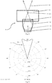
- the light emitter 1 comprises a base plate 11 as a foot, a connected via an adjustable joint 14 with the base plate 11 reflector 12 as optics and a sleeve-shaped aperture 13th
- the base plate 11 is placed on the table top or the workstation 4.
- the light emitter 1 is oriented upward toward the ceiling 5.
- the light emitter 1 comprises a COB LED illuminant 16 as a light source which is mounted in the region of a base of the reflector 12 and which can emit a luminous flux of about 12,500 lumens.
- the reflector 12 is formed as a kind of sleeve with parabolic inner surfaces and is irradiated by the COB LED illuminant 16 emitted light.
- the reflector 12 is designed to form a current of visible light or a luminous flux 41 or a beam from the light generated by the COB LED illuminant 16.
- the luminous flux 41 has a focal point 411 which is upwardly spaced in a radiation direction 161 from the COB LED illuminant 16.
- the aperture 13 is adjustable along the emission direction 161 upwards and downwards. It comprises a substantially sleeve-shaped section penetrated by the luminous flux 41 and light-absorbing on its inner side. In the in Fig. 2 shown setting is the focus 411 of the luminous flux 41 in the sleeve-shaped portion and is thus covered by the aperture 13. The aperture 13 Thus, scattered light from the luminous flux 41 and deblends the light emitter 1 adapted to the particular application.
- the light emitter 1 further comprises a presence sensor 19 and a turn-off unit.
- the presence sensor 19 is aligned in the emission direction 161 and the switch-off unit is designed to automatically switch off the light-emitting means 16 on the basis of a signal generated by the presence sensor 19.
- the reflector 12 is configured to form a light distribution curve 6 of the light generated by the COB LED illuminant 16 as in FIG Fig. 3 to be defined.
- the LVK 6 has a greater light intensity on both sides at about 165 ° than at 180 °. It has at about 165 ° each maximum light intensity.
- the luminous flux 41 generates a virtual luminaire object 51 on the ceiling 5. It is achieved by means of the LVK 6 that the luminaire object 51 has a homogeneous luminance.
- the homogeneous luminance of the luminaire object 51 is at most about 3,000 Cd / m 2 .
- a brightness in the surface of the luminaire 51 changes by less than 3%.
- the luminaire object 51 in turn emits light 42, which corresponds to the reflected light of the luminous flux 41, in the direction of the workstation 4.
- the light 42 of the luminaire object 51 illuminates the workstation 4.
- the sensor unit 3 arranged on the workstation 4 comprises a first communication interface and a sensor with which an illuminance of the light 42 or the light 42 of the luminaire object 51 diverted from the ceiling 5 to the workstation 4 is detected.
- the light emitter 1 is equipped with a second communication interface and an adjusting device. Via the second communication interface and the first communication interface, signals detected by the sensor of the sensor unit 3 can be transmitted to the light emitter 1.
- the adjusting device of the light emitter 1 automatically adjusts the COB LED illuminant 16 on the basis of the signals received by the sensor unit 3, so that the illuminance has a predefined minimum value at the workstation 4 of approximately 500 lux.
- the light emitter 1 further has a transparent cover 17, which covers the reflector 12 upwards. In operation, the luminous flux 41 is passed through the cover 17 after passing through the reflector 12.
- the light emitter 1 further comprises a further sensor 15, which is placed on the base plate 11 and with which the illuminance of the light 42 of the luminaire object 51 is detected.
- the adjusting device of the light emitter 1 automatically adjusts the COB LED illuminant 16 on the basis of signals detected by the further sensor 15, so that the illuminance has the predefined minimum value of approximately 500 lux.
- the further sensor 15 supplements the sensor unit 3 and the two can optionally be switched on and off.
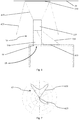
- Fig. 4 shows a second embodiment of an inventive light emitter system 20 with a second embodiment of a light emitter 10.
- the light emitter system 20 is in an office room with a ceiling 5 and a desk set up. A top of a table top of the desk forms a workstation 40.
- the light emitter 19 is formed as a floor lamp with a foot having leg 150.
- the light emitter 10 has a lamp body 130 carried by the leg 150, which is similar in terms of lighting technology to that of the first light emitter of FIG Fig. 2 is trained.
- it comprises an upper COB LED illuminant as lighting means, which can emit a luminous flux of about 12,500 lumens upward via an upper reflector, a lower LED illuminant as direct illuminant and a lower reflector assigned to the lower LED illuminant as direct light optics, which together can output direct light 430 downwards.
- the lamp body 130 is also equipped with an upper reflector, which is designed to form a stream of visible light or a luminous flux 410 or a beam from the light generated by the upper COB LED illuminant.
- the luminous flux 410 is aligned upward toward the ceiling 51.
- the reflector and the lower reflector are configured to provide a light distribution curve 60 of the light generated by the COB LED illuminant and the LED illuminant, as in FIG Fig. 5 to be defined.
- the LVK 60 has an indirect light component 610 and a direct light component 620.
- the indirect light component 610 describes on both sides at about 165 ° a greater light intensity than at 180 °.
- Of the Direct light component 620 is almost opposite to the indirect light component 610. He describes on both sides at about 40 ° a greater light intensity than at 0 °.
- the maximum light intensity of the entire LVK 60 lies in the indirect light component 610 on both sides at about 165 ° each.
- the luminous flux 410 generates a virtual luminaire object 510 on the ceiling 50. It is achieved by means of the LVK 60 that the luminaire object 510 has a homogeneous luminance.
- the homogeneous luminance of the luminaire object 510 is a maximum of about 3,000 Cd / m 2 .
- a brightness in the surface of the luminaire object 510 changes by less than 3%.
- the luminaire object 510 in turn emits light 420, which corresponds to the reflected light of the luminous flux 410, downwards.
- the direct light 430 radiates downwards and illuminates the workplace evenly in an illuminated area 440.
- a third embodiment of an inventive light emitter system 29 is shown with a third embodiment of a light emitter 19.
- the light emitter system 29 is similar to the light emitter system 20 of FIG Fig. 4 formed with a lighting means, a direct light and associated reflectors having lamp body 139. It is arranged in an office room with a ceiling 50 and a workstation 49.
- the upper luminous means and the associated upper reflector are configured to generate an indirect light component 619 of a LVK 69, which is formed analogously to the indirect light component 610 of the LVK 60 of the light radiator 20.
- the lower luminous means or the direct light illuminant and the associated lower reflector are arranged such that an asymmetrical direct light component 629 of the LVK 69 is generated.
- the direct light component 629 is directed only to the right and has a maximum at almost 60 °.
- Fig. 6 As in Fig. 6 is best seen, it allows this design of the LVK 69 on the one hand a basic lighting in the room and on the other hand on the workstation 49 obliquely to produce an illuminated surface 449. This allows the light emitter 19 to be set up laterally next to the illuminated area 449 on the workstation 49.
- the light emitter 19 is equipped with a table base 159 for this purpose.
- the present disclosure also includes embodiments having any combination of features that are mentioned or shown above or below various embodiments. It also comprises individual features in the figures, even if they are shown there in connection with other features and / or are not mentioned above or below. Also, the alternatives of embodiments and individual alternatives described in the figures and the description may be excluded from the subject matter of the invention or from the disclosed subject matter.
- the disclosure includes embodiments which exclusively comprise the features described in the claims and in the exemplary embodiments as well as those which include additional other features.
Landscapes
- Engineering & Computer Science (AREA)
- General Engineering & Computer Science (AREA)
- Health & Medical Sciences (AREA)
- Public Health (AREA)
- Non-Portable Lighting Devices Or Systems Thereof (AREA)
Applications Claiming Priority (2)
| Application Number | Priority Date | Filing Date | Title |
|---|---|---|---|
| CH00569/17A CH713727A1 (de) | 2017-04-28 | 2017-04-28 | Lichtstrahler sowie Lichtstrahlersystem und Arbeitsplatzmöbel mit einem solchen. |
| CH1242018 | 2018-02-02 |
Publications (2)
| Publication Number | Publication Date |
|---|---|
| EP3396242A1 true EP3396242A1 (fr) | 2018-10-31 |
| EP3396242B1 EP3396242B1 (fr) | 2021-11-24 |
Family
ID=62002593
Family Applications (1)
| Application Number | Title | Priority Date | Filing Date |
|---|---|---|---|
| EP18169707.9A Active EP3396242B1 (fr) | 2017-04-28 | 2018-04-27 | Projecteur de lumière ainsi que système de projecteur et meuble de travail pourvu d'un tel projecteur de lumière |
Country Status (1)
| Country | Link |
|---|---|
| EP (1) | EP3396242B1 (fr) |
Cited By (2)
| Publication number | Priority date | Publication date | Assignee | Title |
|---|---|---|---|---|
| EP3910233A1 (fr) | 2020-05-13 | 2021-11-17 | Regent Beleuchtungskörper AG | Luminaire |
| CN118391622A (zh) * | 2024-06-21 | 2024-07-26 | 广州市施亮照明科技有限公司 | 照明装置的控制方法 |
Citations (9)
| Publication number | Priority date | Publication date | Assignee | Title |
|---|---|---|---|---|
| US4001575A (en) * | 1975-05-27 | 1977-01-04 | Johns-Manville Corporation | Luminaire and luminaire arrangement for lighting the ceiling within a room |
| US4218727A (en) * | 1978-07-03 | 1980-08-19 | Sylvan R. Shemitz And Associates, Inc. | Luminaire |
| US4386392A (en) * | 1980-11-17 | 1983-05-31 | Whiteway Manufacturing Co. | Lighting unit for providing indirect light of uniform intensity |
| US4667275A (en) * | 1979-06-08 | 1987-05-19 | Peerless Lighting Corporation | Luminaire for indirect lighting |
| US20120257383A1 (en) * | 2011-04-08 | 2012-10-11 | Lunera Lighting Inc. | Light well providing wide angle up lighting in a led luminaire |
| WO2015074154A1 (fr) * | 2013-11-22 | 2015-05-28 | Fluxwerx Illumination Inc. | Éléments d'extraction de lumière pour une distribution de lumière indirecte |
| US20150285450A1 (en) * | 2012-10-19 | 2015-10-08 | Koninklijke Philips N.V. | Lighting device for indirect illumination |
| US20150373806A1 (en) * | 2013-01-25 | 2015-12-24 | Koninklijke Philips N.V. | Lighting device and lighting system |
| WO2016171505A1 (fr) * | 2015-04-23 | 2016-10-27 | 주식회사 케이엠더블유 | Dispositif d'éclairage à led |
-
2018
- 2018-04-27 EP EP18169707.9A patent/EP3396242B1/fr active Active
Patent Citations (9)
| Publication number | Priority date | Publication date | Assignee | Title |
|---|---|---|---|---|
| US4001575A (en) * | 1975-05-27 | 1977-01-04 | Johns-Manville Corporation | Luminaire and luminaire arrangement for lighting the ceiling within a room |
| US4218727A (en) * | 1978-07-03 | 1980-08-19 | Sylvan R. Shemitz And Associates, Inc. | Luminaire |
| US4667275A (en) * | 1979-06-08 | 1987-05-19 | Peerless Lighting Corporation | Luminaire for indirect lighting |
| US4386392A (en) * | 1980-11-17 | 1983-05-31 | Whiteway Manufacturing Co. | Lighting unit for providing indirect light of uniform intensity |
| US20120257383A1 (en) * | 2011-04-08 | 2012-10-11 | Lunera Lighting Inc. | Light well providing wide angle up lighting in a led luminaire |
| US20150285450A1 (en) * | 2012-10-19 | 2015-10-08 | Koninklijke Philips N.V. | Lighting device for indirect illumination |
| US20150373806A1 (en) * | 2013-01-25 | 2015-12-24 | Koninklijke Philips N.V. | Lighting device and lighting system |
| WO2015074154A1 (fr) * | 2013-11-22 | 2015-05-28 | Fluxwerx Illumination Inc. | Éléments d'extraction de lumière pour une distribution de lumière indirecte |
| WO2016171505A1 (fr) * | 2015-04-23 | 2016-10-27 | 주식회사 케이엠더블유 | Dispositif d'éclairage à led |
Cited By (2)
| Publication number | Priority date | Publication date | Assignee | Title |
|---|---|---|---|---|
| EP3910233A1 (fr) | 2020-05-13 | 2021-11-17 | Regent Beleuchtungskörper AG | Luminaire |
| CN118391622A (zh) * | 2024-06-21 | 2024-07-26 | 广州市施亮照明科技有限公司 | 照明装置的控制方法 |
Also Published As
| Publication number | Publication date |
|---|---|
| EP3396242B1 (fr) | 2021-11-24 |
Similar Documents
| Publication | Publication Date | Title |
|---|---|---|
| EP2239494B1 (fr) | Agencement destiné à l'éclairage ambiant | |
| EP3555521B1 (fr) | Dispositif d'éclairage | |
| DE102010044353A1 (de) | Steh- oder Tischleuchte | |
| EP3172483B1 (fr) | Dispositif d'éclairage général et procédé de commande d'un tel dispositif | |
| WO2011098063A1 (fr) | Luminaire encastré | |
| EP3187773B1 (fr) | Corps lumineux et lampadaire | |
| EP3396242B1 (fr) | Projecteur de lumière ainsi que système de projecteur et meuble de travail pourvu d'un tel projecteur de lumière | |
| EP0677697B1 (fr) | Appareil d'éclairage pour plan de travail | |
| CH700022B1 (de) | Stehleuchte. | |
| CH713727A1 (de) | Lichtstrahler sowie Lichtstrahlersystem und Arbeitsplatzmöbel mit einem solchen. | |
| EP1361391A2 (fr) | Lampe pour l'éclairage d'un poste de travail | |
| EP3745020B1 (fr) | Luminaire | |
| EP2989378B1 (fr) | Lampe à led à distributions lumineuses réglables | |
| EP3081855B1 (fr) | Projecteur | |
| EP3910233B1 (fr) | Luminaire | |
| EP3276255B1 (fr) | Système d'éclairage | |
| WO2022106677A1 (fr) | Système d'éclairage et procédé pour produire une tache de lumière de taille réglable | |
| DE9209625U1 (de) | Leuchte, insbesondere Büroleuchte | |
| AT413438B (de) | Leuchte | |
| CH712751A1 (de) | Beleuchtungssystem. | |
| EP4279799A1 (fr) | Lampe pour bureau ou lampadaire pour postes de travail | |
| DE102022130698A1 (de) | Verfahren und Beleuchtungsvorrichtung zum Beleuchten von Wandflächen | |
| EP4063728A1 (fr) | Luminaire | |
| DE1912909U (de) | Leuchte. |
Legal Events
| Date | Code | Title | Description |
|---|---|---|---|
| PUAI | Public reference made under article 153(3) epc to a published international application that has entered the european phase |
Free format text: ORIGINAL CODE: 0009012 |
|
| STAA | Information on the status of an ep patent application or granted ep patent |
Free format text: STATUS: THE APPLICATION HAS BEEN PUBLISHED |
|
| AK | Designated contracting states |
Kind code of ref document: A1 Designated state(s): AL AT BE BG CH CY CZ DE DK EE ES FI FR GB GR HR HU IE IS IT LI LT LU LV MC MK MT NL NO PL PT RO RS SE SI SK SM TR |
|
| AX | Request for extension of the european patent |
Extension state: BA ME |
|
| STAA | Information on the status of an ep patent application or granted ep patent |
Free format text: STATUS: REQUEST FOR EXAMINATION WAS MADE |
|
| 17P | Request for examination filed |
Effective date: 20190429 |
|
| RBV | Designated contracting states (corrected) |
Designated state(s): AL AT BE BG CH CY CZ DE DK EE ES FI FR GB GR HR HU IE IS IT LI LT LU LV MC MK MT NL NO PL PT RO RS SE SI SK SM TR |
|
| STAA | Information on the status of an ep patent application or granted ep patent |
Free format text: STATUS: EXAMINATION IS IN PROGRESS |
|
| 17Q | First examination report despatched |
Effective date: 20190801 |
|
| GRAP | Despatch of communication of intention to grant a patent |
Free format text: ORIGINAL CODE: EPIDOSNIGR1 |
|
| STAA | Information on the status of an ep patent application or granted ep patent |
Free format text: STATUS: GRANT OF PATENT IS INTENDED |
|
| RIC1 | Information provided on ipc code assigned before grant |
Ipc: F21V 14/08 20060101ALN20200224BHEP Ipc: F21W 131/402 20060101ALN20200224BHEP Ipc: F21S 6/00 20060101ALI20200224BHEP Ipc: F21V 23/04 20060101ALN20200224BHEP Ipc: F21V 7/00 20060101AFI20200224BHEP Ipc: F21V 13/10 20060101ALI20200224BHEP Ipc: F21V 33/00 20060101ALI20200224BHEP Ipc: F21Y 115/10 20160101ALN20200224BHEP |
|
| INTG | Intention to grant announced |
Effective date: 20200311 |
|
| GRAJ | Information related to disapproval of communication of intention to grant by the applicant or resumption of examination proceedings by the epo deleted |
Free format text: ORIGINAL CODE: EPIDOSDIGR1 |
|
| STAA | Information on the status of an ep patent application or granted ep patent |
Free format text: STATUS: EXAMINATION IS IN PROGRESS |
|
| INTC | Intention to grant announced (deleted) | ||
| GRAS | Grant fee paid |
Free format text: ORIGINAL CODE: EPIDOSNIGR3 |
|
| STAA | Information on the status of an ep patent application or granted ep patent |
Free format text: STATUS: GRANT OF PATENT IS INTENDED |
|
| GRAP | Despatch of communication of intention to grant a patent |
Free format text: ORIGINAL CODE: EPIDOSNIGR1 |
|
| RIC1 | Information provided on ipc code assigned before grant |
Ipc: F21V 7/00 20060101AFI20210521BHEP Ipc: F21V 33/00 20060101ALI20210521BHEP Ipc: F21V 13/10 20060101ALI20210521BHEP Ipc: F21S 6/00 20060101ALI20210521BHEP Ipc: F21V 14/08 20060101ALN20210521BHEP Ipc: F21V 23/04 20060101ALN20210521BHEP Ipc: F21Y 115/10 20160101ALN20210521BHEP Ipc: F21W 131/402 20060101ALN20210521BHEP |
|
| INTG | Intention to grant announced |
Effective date: 20210617 |
|
| GRAA | (expected) grant |
Free format text: ORIGINAL CODE: 0009210 |
|
| STAA | Information on the status of an ep patent application or granted ep patent |
Free format text: STATUS: THE PATENT HAS BEEN GRANTED |
|
| AK | Designated contracting states |
Kind code of ref document: B1 Designated state(s): AL AT BE BG CH CY CZ DE DK EE ES FI FR GB GR HR HU IE IS IT LI LT LU LV MC MK MT NL NO PL PT RO RS SE SI SK SM TR |
|
| REG | Reference to a national code |
Ref country code: GB Ref legal event code: FG4D Free format text: NOT ENGLISH |
|
| REG | Reference to a national code |
Ref country code: DE Ref legal event code: R096 Ref document number: 502018007938 Country of ref document: DE |
|
| REG | Reference to a national code |
Ref country code: AT Ref legal event code: REF Ref document number: 1450133 Country of ref document: AT Kind code of ref document: T Effective date: 20211215 |
|
| REG | Reference to a national code |
Ref country code: IE Ref legal event code: FG4D Free format text: LANGUAGE OF EP DOCUMENT: GERMAN |
|
| REG | Reference to a national code |
Ref country code: LT Ref legal event code: MG9D |
|
| REG | Reference to a national code |
Ref country code: NL Ref legal event code: MP Effective date: 20211124 |
|
| PG25 | Lapsed in a contracting state [announced via postgrant information from national office to epo] |
Ref country code: RS Free format text: LAPSE BECAUSE OF FAILURE TO SUBMIT A TRANSLATION OF THE DESCRIPTION OR TO PAY THE FEE WITHIN THE PRESCRIBED TIME-LIMIT Effective date: 20211124 Ref country code: LT Free format text: LAPSE BECAUSE OF FAILURE TO SUBMIT A TRANSLATION OF THE DESCRIPTION OR TO PAY THE FEE WITHIN THE PRESCRIBED TIME-LIMIT Effective date: 20211124 Ref country code: FI Free format text: LAPSE BECAUSE OF FAILURE TO SUBMIT A TRANSLATION OF THE DESCRIPTION OR TO PAY THE FEE WITHIN THE PRESCRIBED TIME-LIMIT Effective date: 20211124 Ref country code: BG Free format text: LAPSE BECAUSE OF FAILURE TO SUBMIT A TRANSLATION OF THE DESCRIPTION OR TO PAY THE FEE WITHIN THE PRESCRIBED TIME-LIMIT Effective date: 20220224 |
|
| PG25 | Lapsed in a contracting state [announced via postgrant information from national office to epo] |
Ref country code: IS Free format text: LAPSE BECAUSE OF FAILURE TO SUBMIT A TRANSLATION OF THE DESCRIPTION OR TO PAY THE FEE WITHIN THE PRESCRIBED TIME-LIMIT Effective date: 20220324 Ref country code: SE Free format text: LAPSE BECAUSE OF FAILURE TO SUBMIT A TRANSLATION OF THE DESCRIPTION OR TO PAY THE FEE WITHIN THE PRESCRIBED TIME-LIMIT Effective date: 20211124 Ref country code: PT Free format text: LAPSE BECAUSE OF FAILURE TO SUBMIT A TRANSLATION OF THE DESCRIPTION OR TO PAY THE FEE WITHIN THE PRESCRIBED TIME-LIMIT Effective date: 20220324 Ref country code: PL Free format text: LAPSE BECAUSE OF FAILURE TO SUBMIT A TRANSLATION OF THE DESCRIPTION OR TO PAY THE FEE WITHIN THE PRESCRIBED TIME-LIMIT Effective date: 20211124 Ref country code: NO Free format text: LAPSE BECAUSE OF FAILURE TO SUBMIT A TRANSLATION OF THE DESCRIPTION OR TO PAY THE FEE WITHIN THE PRESCRIBED TIME-LIMIT Effective date: 20220224 Ref country code: NL Free format text: LAPSE BECAUSE OF FAILURE TO SUBMIT A TRANSLATION OF THE DESCRIPTION OR TO PAY THE FEE WITHIN THE PRESCRIBED TIME-LIMIT Effective date: 20211124 Ref country code: LV Free format text: LAPSE BECAUSE OF FAILURE TO SUBMIT A TRANSLATION OF THE DESCRIPTION OR TO PAY THE FEE WITHIN THE PRESCRIBED TIME-LIMIT Effective date: 20211124 Ref country code: HR Free format text: LAPSE BECAUSE OF FAILURE TO SUBMIT A TRANSLATION OF THE DESCRIPTION OR TO PAY THE FEE WITHIN THE PRESCRIBED TIME-LIMIT Effective date: 20211124 Ref country code: GR Free format text: LAPSE BECAUSE OF FAILURE TO SUBMIT A TRANSLATION OF THE DESCRIPTION OR TO PAY THE FEE WITHIN THE PRESCRIBED TIME-LIMIT Effective date: 20220225 Ref country code: ES Free format text: LAPSE BECAUSE OF FAILURE TO SUBMIT A TRANSLATION OF THE DESCRIPTION OR TO PAY THE FEE WITHIN THE PRESCRIBED TIME-LIMIT Effective date: 20211124 |
|
| PG25 | Lapsed in a contracting state [announced via postgrant information from national office to epo] |
Ref country code: SM Free format text: LAPSE BECAUSE OF FAILURE TO SUBMIT A TRANSLATION OF THE DESCRIPTION OR TO PAY THE FEE WITHIN THE PRESCRIBED TIME-LIMIT Effective date: 20211124 Ref country code: SK Free format text: LAPSE BECAUSE OF FAILURE TO SUBMIT A TRANSLATION OF THE DESCRIPTION OR TO PAY THE FEE WITHIN THE PRESCRIBED TIME-LIMIT Effective date: 20211124 Ref country code: RO Free format text: LAPSE BECAUSE OF FAILURE TO SUBMIT A TRANSLATION OF THE DESCRIPTION OR TO PAY THE FEE WITHIN THE PRESCRIBED TIME-LIMIT Effective date: 20211124 Ref country code: EE Free format text: LAPSE BECAUSE OF FAILURE TO SUBMIT A TRANSLATION OF THE DESCRIPTION OR TO PAY THE FEE WITHIN THE PRESCRIBED TIME-LIMIT Effective date: 20211124 Ref country code: DK Free format text: LAPSE BECAUSE OF FAILURE TO SUBMIT A TRANSLATION OF THE DESCRIPTION OR TO PAY THE FEE WITHIN THE PRESCRIBED TIME-LIMIT Effective date: 20211124 Ref country code: CZ Free format text: LAPSE BECAUSE OF FAILURE TO SUBMIT A TRANSLATION OF THE DESCRIPTION OR TO PAY THE FEE WITHIN THE PRESCRIBED TIME-LIMIT Effective date: 20211124 |
|
| REG | Reference to a national code |
Ref country code: DE Ref legal event code: R097 Ref document number: 502018007938 Country of ref document: DE |
|
| PLBE | No opposition filed within time limit |
Free format text: ORIGINAL CODE: 0009261 |
|
| STAA | Information on the status of an ep patent application or granted ep patent |
Free format text: STATUS: NO OPPOSITION FILED WITHIN TIME LIMIT |
|
| PG25 | Lapsed in a contracting state [announced via postgrant information from national office to epo] |
Ref country code: AL Free format text: LAPSE BECAUSE OF FAILURE TO SUBMIT A TRANSLATION OF THE DESCRIPTION OR TO PAY THE FEE WITHIN THE PRESCRIBED TIME-LIMIT Effective date: 20211124 |
|
| 26N | No opposition filed |
Effective date: 20220825 |
|
| PG25 | Lapsed in a contracting state [announced via postgrant information from national office to epo] |
Ref country code: SI Free format text: LAPSE BECAUSE OF FAILURE TO SUBMIT A TRANSLATION OF THE DESCRIPTION OR TO PAY THE FEE WITHIN THE PRESCRIBED TIME-LIMIT Effective date: 20211124 |
|
| GBPC | Gb: european patent ceased through non-payment of renewal fee |
Effective date: 20220427 |
|
| REG | Reference to a national code |
Ref country code: BE Ref legal event code: MM Effective date: 20220430 |
|
| PG25 | Lapsed in a contracting state [announced via postgrant information from national office to epo] |
Ref country code: MC Free format text: LAPSE BECAUSE OF FAILURE TO SUBMIT A TRANSLATION OF THE DESCRIPTION OR TO PAY THE FEE WITHIN THE PRESCRIBED TIME-LIMIT Effective date: 20211124 Ref country code: LU Free format text: LAPSE BECAUSE OF NON-PAYMENT OF DUE FEES Effective date: 20220427 Ref country code: GB Free format text: LAPSE BECAUSE OF NON-PAYMENT OF DUE FEES Effective date: 20220427 |
|
| PG25 | Lapsed in a contracting state [announced via postgrant information from national office to epo] |
Ref country code: BE Free format text: LAPSE BECAUSE OF NON-PAYMENT OF DUE FEES Effective date: 20220430 |
|
| PG25 | Lapsed in a contracting state [announced via postgrant information from national office to epo] |
Ref country code: IE Free format text: LAPSE BECAUSE OF NON-PAYMENT OF DUE FEES Effective date: 20220427 |
|
| PG25 | Lapsed in a contracting state [announced via postgrant information from national office to epo] |
Ref country code: IT Free format text: LAPSE BECAUSE OF FAILURE TO SUBMIT A TRANSLATION OF THE DESCRIPTION OR TO PAY THE FEE WITHIN THE PRESCRIBED TIME-LIMIT Effective date: 20211124 |
|
| P01 | Opt-out of the competence of the unified patent court (upc) registered |
Effective date: 20230529 |
|
| PG25 | Lapsed in a contracting state [announced via postgrant information from national office to epo] |
Ref country code: HU Free format text: LAPSE BECAUSE OF FAILURE TO SUBMIT A TRANSLATION OF THE DESCRIPTION OR TO PAY THE FEE WITHIN THE PRESCRIBED TIME-LIMIT; INVALID AB INITIO Effective date: 20180427 |
|
| PG25 | Lapsed in a contracting state [announced via postgrant information from national office to epo] |
Ref country code: MK Free format text: LAPSE BECAUSE OF FAILURE TO SUBMIT A TRANSLATION OF THE DESCRIPTION OR TO PAY THE FEE WITHIN THE PRESCRIBED TIME-LIMIT Effective date: 20211124 Ref country code: CY Free format text: LAPSE BECAUSE OF FAILURE TO SUBMIT A TRANSLATION OF THE DESCRIPTION OR TO PAY THE FEE WITHIN THE PRESCRIBED TIME-LIMIT Effective date: 20211124 |
|
| PG25 | Lapsed in a contracting state [announced via postgrant information from national office to epo] |
Ref country code: TR Free format text: LAPSE BECAUSE OF FAILURE TO SUBMIT A TRANSLATION OF THE DESCRIPTION OR TO PAY THE FEE WITHIN THE PRESCRIBED TIME-LIMIT Effective date: 20211124 |
|
| PG25 | Lapsed in a contracting state [announced via postgrant information from national office to epo] |
Ref country code: MT Free format text: LAPSE BECAUSE OF FAILURE TO SUBMIT A TRANSLATION OF THE DESCRIPTION OR TO PAY THE FEE WITHIN THE PRESCRIBED TIME-LIMIT Effective date: 20211124 |
|
| PGFP | Annual fee paid to national office [announced via postgrant information from national office to epo] |
Ref country code: DE Payment date: 20250422 Year of fee payment: 8 |
|
| PGFP | Annual fee paid to national office [announced via postgrant information from national office to epo] |
Ref country code: FR Payment date: 20250425 Year of fee payment: 8 |
|
| PGFP | Annual fee paid to national office [announced via postgrant information from national office to epo] |
Ref country code: CH Payment date: 20250501 Year of fee payment: 8 |
|
| PGFP | Annual fee paid to national office [announced via postgrant information from national office to epo] |
Ref country code: AT Payment date: 20250423 Year of fee payment: 8 |