EP3396244A1 - Beleuchtungskörper - Google Patents
Beleuchtungskörper Download PDFInfo
- Publication number
- EP3396244A1 EP3396244A1 EP17168349.3A EP17168349A EP3396244A1 EP 3396244 A1 EP3396244 A1 EP 3396244A1 EP 17168349 A EP17168349 A EP 17168349A EP 3396244 A1 EP3396244 A1 EP 3396244A1
- Authority
- EP
- European Patent Office
- Prior art keywords
- gable
- base frame
- light fixture
- axis
- side portion
- Prior art date
- Legal status (The legal status is an assumption and is not a legal conclusion. Google has not performed a legal analysis and makes no representation as to the accuracy of the status listed.)
- Granted
Links
Images




Classifications
-
- F—MECHANICAL ENGINEERING; LIGHTING; HEATING; WEAPONS; BLASTING
- F21—LIGHTING
- F21V—FUNCTIONAL FEATURES OR DETAILS OF LIGHTING DEVICES OR SYSTEMS THEREOF; STRUCTURAL COMBINATIONS OF LIGHTING DEVICES WITH OTHER ARTICLES, NOT OTHERWISE PROVIDED FOR
- F21V17/00—Fastening of component parts of lighting devices, e.g. shades, globes, refractors, reflectors, filters, screens, grids or protective cages
- F21V17/10—Fastening of component parts of lighting devices, e.g. shades, globes, refractors, reflectors, filters, screens, grids or protective cages characterised by specific fastening means or way of fastening
- F21V17/105—Fastening of component parts of lighting devices, e.g. shades, globes, refractors, reflectors, filters, screens, grids or protective cages characterised by specific fastening means or way of fastening using magnets
-
- F—MECHANICAL ENGINEERING; LIGHTING; HEATING; WEAPONS; BLASTING
- F21—LIGHTING
- F21V—FUNCTIONAL FEATURES OR DETAILS OF LIGHTING DEVICES OR SYSTEMS THEREOF; STRUCTURAL COMBINATIONS OF LIGHTING DEVICES WITH OTHER ARTICLES, NOT OTHERWISE PROVIDED FOR
- F21V15/00—Protecting lighting devices from damage
- F21V15/01—Housings, e.g. material or assembling of housing parts
- F21V15/015—Devices for covering joints between adjacent lighting devices; End coverings
-
- F—MECHANICAL ENGINEERING; LIGHTING; HEATING; WEAPONS; BLASTING
- F21—LIGHTING
- F21V—FUNCTIONAL FEATURES OR DETAILS OF LIGHTING DEVICES OR SYSTEMS THEREOF; STRUCTURAL COMBINATIONS OF LIGHTING DEVICES WITH OTHER ARTICLES, NOT OTHERWISE PROVIDED FOR
- F21V17/00—Fastening of component parts of lighting devices, e.g. shades, globes, refractors, reflectors, filters, screens, grids or protective cages
- F21V17/10—Fastening of component parts of lighting devices, e.g. shades, globes, refractors, reflectors, filters, screens, grids or protective cages characterised by specific fastening means or way of fastening
- F21V17/107—Fastening of component parts of lighting devices, e.g. shades, globes, refractors, reflectors, filters, screens, grids or protective cages characterised by specific fastening means or way of fastening using hinge joints
-
- F—MECHANICAL ENGINEERING; LIGHTING; HEATING; WEAPONS; BLASTING
- F21—LIGHTING
- F21V—FUNCTIONAL FEATURES OR DETAILS OF LIGHTING DEVICES OR SYSTEMS THEREOF; STRUCTURAL COMBINATIONS OF LIGHTING DEVICES WITH OTHER ARTICLES, NOT OTHERWISE PROVIDED FOR
- F21V3/00—Globes; Bowls; Cover glasses
- F21V3/04—Globes; Bowls; Cover glasses characterised by materials, surface treatments or coatings
- F21V3/06—Globes; Bowls; Cover glasses characterised by materials, surface treatments or coatings characterised by the material
- F21V3/062—Globes; Bowls; Cover glasses characterised by materials, surface treatments or coatings characterised by the material the material being plastics
-
- F—MECHANICAL ENGINEERING; LIGHTING; HEATING; WEAPONS; BLASTING
- F21—LIGHTING
- F21S—NON-PORTABLE LIGHTING DEVICES; SYSTEMS THEREOF; VEHICLE LIGHTING DEVICES SPECIALLY ADAPTED FOR VEHICLE EXTERIORS
- F21S8/00—Lighting devices intended for fixed installation
- F21S8/04—Lighting devices intended for fixed installation intended only for mounting on a ceiling or the like overhead structures
-
- F—MECHANICAL ENGINEERING; LIGHTING; HEATING; WEAPONS; BLASTING
- F21—LIGHTING
- F21V—FUNCTIONAL FEATURES OR DETAILS OF LIGHTING DEVICES OR SYSTEMS THEREOF; STRUCTURAL COMBINATIONS OF LIGHTING DEVICES WITH OTHER ARTICLES, NOT OTHERWISE PROVIDED FOR
- F21V3/00—Globes; Bowls; Cover glasses
Definitions
- the present disclosure relates to a light fixture, and especially an arrangement for facilitating mounting and maintenance of a light fixture.
- a light fixture comprising a base frame extending longitudinally along a first axis, a translucent cover arranged to the base frame and at least one gable.
- the light fixture is characterized in that the at least one gable is rotationally moveable around a second axis relative to the base frame between an open position and a closed position, such that the translucent cover is fixed relative to the base frame by the at least one gable being in the closed position, and that the translucent cover is removable from the base frame when the at least one gable is in the open position.
- the at least one gable can be rotated from an open position to a closed position and when in the open position allows for the translucent cover to be removed without use of force or tools that may cause damage to the translucent cover. Further, after mounting of the light fixture, maintenance of the light fixture may be performed by simply rotating the gables into the open position and removing the translucent cover.
- the base frame provides support and rigidity to the light fixture as well as that it provides an area for mounting the light fixture to a ceiling, wall, or other suitable surface.
- the translucent cover may be translucent or transparent to spread light over an area or direct light in a certain direction.
- the other gable may in such embodiment be fixedly attached to the base frame, or be provided as an integrated portion of the base frame. Only one rotatable gable may provide a simpler and more cost-efficient fixture, with kept functionality of removability of the translucent cover.
- the first axis of the base frame may be perpendicular to the second axis of the base frame.
- the first axis provides the axis of extension of the base frame and the second axis provides the central axis of rotation for the gable.
- the second axis may further be located on a longitudinal end of the base frame.
- a hinge may be arranged to the base frame, wherein the gable is suspended to the base frame by the hinge, and wherein the hinge provides the rotatability of the gable around the second axis.
- the hinge may be arranged at a distance from a side portion of the base frame, where the side portion extends in a direction parallel to the second axis, such as to form a space between the gable and an outer side of the side portion.
- Arranging the hinge at a distance from the side portion moves the axis of rotation of the gable further along the first axis which provides a space between the side portion and the side of the gable facing the side portion.
- Such space may be useful for arrangement of fixture components, such as cables received by the fixture.
- the side portion may further extend in a direction perpendicular to the first axis.
- the hinge is arranged at a distance from an outer surface of the side portion, which outer surface faces an inner side of the gable.
- the gable may be rotatable at least 5 degrees, preferably between 5-45 degrees, more preferably between 5-25 degrees, most preferably between 5-15 degrees, around the second axis between the closed position and the open position. The rotation of the gable provides space for the translucent cover to be released from the base frame.
- the at least on gable may extend in the direction of the first axis such that an end portion of the translucent cover is held fixed relative to the base frame when the at least one gable is in the closed position.
- the gable may extend from one longitudinal end of the base frame towards the other longitudinal end of the base frame such that a portion of the translucent cover is covered by the gable and held into position such that the translucent cover may be prevented from falling off or being removed by other means from the base frame when the gable is in the closed position.
- the end portion of the translucent cover may rest on a holding portion of the gable, when the gable is in the closed position.
- the base frame may comprise a first and a second side portion extending in a direction parallel to the second axis.
- the first and second side portions may comprise an outer side facing the gable and an inner side facing an interior of the base frame.
- the translucent cover may be configured to extend between the inner sides of the first and second side portions, and the gable may comprise a holding portion which in the closed position may be configured to extend past the first and second side portions in direction from the outer side to the inner side thereof to hold the end portion of the translucent cover.
- the first and second side portions may provide a barrier between the space between the gable and the side portion and the space of the interior of the light fixture.
- the first and second side portions may further provide support and an area of attachment to the base frame for the hinge.
- the first and second side portions may further extend in a direction perpendicular to the first axis.
- the base frame may comprise a third and fourth side portion extending along the longitudinal direction of the base frame.
- Each of the third and fourth side portion may comprise an outer side facing the exterior of the base frame and an inner side facing the interior of the base frame.
- the translucent cover may be arranged to abut the inner side of the third and fourth side portion respectively.
- the third and fourth sides together with the first and second sides of the base frame may form a rectangular shape which construct the base frame.
- the abutment between the translucent cover and the third and fourth sides may serve to suspend the translucent cover to the base frame when the gable is in the open position such as to prevent uncontrolled removal of the translucent cover or that it falls or loosens from the frame in an uncontrolled manner.
- the light fixture may further comprise a base side arranged between the first through fourth sides and opposite the translucent cover.
- the base side may be configured to be fastened to a ceiling or wall or other suitable surface to which to arrange the light fixture.
- the holding portion of the gable may extend past the first and second portions and may extend such that it extends past the first and second side portions and covers part of the third and fourth sides and the end portion of the translucent cover while leaving the base side uncovered such as to allow for rotation of the gable without limitation or disturbance from the back side of the base frame.
- the at least one gable may be held in the closed position by means of attaching means.
- the attaching means may serve to keep the gable in the closed position such as to prevent unintentional rotation of the gable into the open position and thus preventing the translucent cover from falling off or getting loose unintentionally.
- the attaching means may provide that a force above a threshold force level is required in order to move the gable to the open position.
- the attaching means may comprise at least one first attaching member and at least one second attaching member configured to adhere to each other.
- the first and second members may adhere to each other when the gable is in the closed position and may be non-adherent when the gable is in the open position.
- One of the attaching members may be arranged on the gable, and the other one on a side portion of the base frame.
- one of the attaching members may be arranged on an inner side of the gable, facing the side portion, and the other attaching member may be arranged on an outer side of the side portion, facing the gable.
- the at least one first and at least one second attaching member may correspond to a at least one first and a at least one second magnetic member respectively.
- the first magnetic member may be a magnet and the second magnetic member may be a magnetic material such as a screw or piece of metal.
- the at least one first magnetic member may be arranged on the at least one gable and at least one second magnetic member is arranged on a side portion of the base frame, where the side portion may extend in a direction parallel to the second axis.
- the first magnetic member being arranged on the gable and the second magnetic member being arranged on the side portion may assure that when the gable is rotated into the closed position, the first magnetic member adheres to the second magnetic member on the side portion, indicating that the gable may be kept in the closed position by the magnetic members. Applying a force larger than the magnetic force between the two magnetic members to the gable, and to the first magnetic member, allows for rotation of the gable into the open position and thus for removal of the translucent cover from the base frame.
- the first magnetic member may be arranged on the side portion and the second magnetic member on the gable.
- the base frame may comprise a through hole arranged on a side portion of the base frame, said side portion extending in a direction parallel to the second axis, wherein the through hole is configured to receive cabling, and wherein the through hole constitutes a protruding part of the side portion.
- the through hole may provide means for providing the interior of the light fixture with cabling allowing for electrical features such as LED, light bulbs, fluorescent lamps, or other electrical mean for generation of light inside the light fixture.
- the hinge may be arranged to extend on either side of the protruding part.
- the hinge extending on either side of the protruding part may allow for rotation of the gable without interference with cabling passing through the trough hole.
- the attaching members may be contained in a space formed by the distance between the outer side of the side portion and an inner side of the gable.
- the distance between the inner side of the gable and the outer side of the side portion may provide space to contain the attaching members.
- the at least one gable may comprise an opening arranged to receive the protruding part when the gable is in the closed position.
- the protruding part may extend through the gable.
- the opening in the gable may allow for the cabling to pass through the gable into the light fixture without being obstructed or affected by rotation of the gable between its open and closed positions.
- the base frame may be configured to carry LED lamps and wherein the translucent cover is arranged to cover the LED lamps.
- a method for enabling maintenance of a light fixture may comprise the steps of rotating the at least one gable around the second axis from the closed position to the open position, and removing the translucent cover. Rotation of the gable around the second axis may allow for removal of the translucent cover from the base frame without causing damage to the translucent cover. Removal of the translucent cover may disclose the interior of the light fixture and thus allow for maintenance of the interior of the light fixture or maintenance of the translucent cover.
- the light fixture 1 according to an embodiment of the invention is illustrated in figure 1 .
- the light fixture 1 comprises a base frame 2 which extends longitudinally along a first axis A and is arranged to be mounted to a surface such as a wall or ceiling.
- the light fixture further comprises a translucent cover 3 arranged on the side of the base frame which is facing away from the wall or ceiling.
- Two gables 4 are rotatably arranged to the base frame 2, one on each longitudinal end of the base frame 2.
- the gables 4 are rotatable between a closed position, illustrated in fig. 1 and an open position, illustrated in fig. 2 .
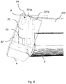
- the gables 4 are rotatable around a second axis B, perpendicular to the first axis A, illustrated in fig. 3 .
- Fig. 3 provides a view of a part of the light fixture 1 with a transparent view of the gable 4 in the closed position.
- the base frame 2 comprises a side portion 221, 222 which comprises an inner side 221 b, 222b facing the interior of the base frame 2 and an outer side 221 a, 222a, facing the interior of the gable 4.
- a first side portion 221 is located on a first side of the base frame 2 and a second side portion 222 located on a second side of the base frame 2.
- the second side portion 222 being identical in terms of function and features as the first side portion 221.
- the gable 4 is arranged to the base frame 2 by a hinge 24.
- the hinge 24 may be arranged with a distance to the to the outer side 221 a, of the side portion 221 of the base frame 2.
- the gable 4 further comprise attaching means that comprise a first attaching member 42 located on a base frame side portion 221, 222 facing side of the gable 4.
- the first attaching member 42 may be a magnet, an adhesive material, velcro, or other suitable material which allows for attachment without the use of additional attaching means such as screws or nails.
- the outer side 221 a of the base frame side portion 221 comprises a second attaching member 23 configured to adhere to the first attaching member 42 when the gable 4 is in the closed position and thus serves to keep the gable 4 in the closed position.
- the second attaching member 23 may be a magnetic material, such as a screw head or piece of metal, or other suitable material adhering to the first attaching member 42.
- a protruding part 25 which extends from the side portion 221, 222 and through the gable 4.
- the protruding part is configured to allow for passage of cabling into the light fixture via a through hole 21.
- the protruding part 25 further allows cabling to pass into the light fixture without causing entanglement of the cabling with the gable 4 when this rotates between its open and closed positions.
- the through hole 21 through the protruding part 25 is illustrated.
- the through hole 21 allows for passage of cabling through the protruding part 25 into the interior of the light fixture 1.
- the gable 4 comprises an opening 41 which is arranged to surround the protruding part 25 when the gable 4 is in the closed position.
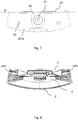
- Fig. 6 illustrates a cross sectional side view of the gable 4.
- the gable 4 comprises two first attaching members 42 arranged one on each side of the opening 41.
- Two corresponding second attaching members 23 are arranged on the outer side 221aof the side portion 221, one on each side of the through hole 21, as illustrated in fig. 7 .
- the base frame 2 comprises a third 223 and fourth 224 side portion which extend between the first 221 and second 222 side portions of the base frame 2, in the longitudinal direction of the base frame 2.
- the third 223 and fourth side portions 224 comprise an outer side facing the exterior of the light fixture 1 and an inner side facing the interior of the light fixture 1.
- the translucent cover 3, when attached to the base frame 2, is configured to abut inner sides of the third 223 and fourth 224 side portions, as illustrated in fig. 8 .
- Fig. 9 and fig. 10 show an exploded view of the base frame 2 and the translucent cover 3.
- the interior of the base frame is adapted to hold LED lamps but can also be used with fluorescent lamps or other means of light transmission.
- the translucent cover 3 aims to spread light evenly or directed to a specific area and also serves to protect the eyes of a user of the light fixture form direct or strong light.
- the base frame 2 and gables 4 are produced from sheet metal, wood, hard plastic or other suitable material for mounting to a wall or ceiling.
- the translucent cover 3 is made of translucent or transparent plastic, which could suitably be a thermo-plastic, preferably PMMA.
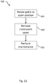
- FIG 11 the method 100 according to an embodiment of the invention is illustrated.
- the gable 4 is rotated 101 from the closed position to the open position by applying a force lager than the force of the attaching members 42, 23.
- the gables 4 are rotated 101 into the open position, the translucent cover 3 can be removed 102. After removal 102 of the translucent cover 3 maintenance 103 is performed.
Landscapes
- Engineering & Computer Science (AREA)
- General Engineering & Computer Science (AREA)
- Non-Portable Lighting Devices Or Systems Thereof (AREA)
- Securing Globes, Refractors, Reflectors Or The Like (AREA)
Priority Applications (2)
| Application Number | Priority Date | Filing Date | Title |
|---|---|---|---|
| EP17168349.3A EP3396244B8 (de) | 2017-04-27 | 2017-04-27 | Beleuchtungskörper |
| DK17168349.3T DK3396244T3 (da) | 2017-04-27 | 2017-04-27 | Lysarmatur |
Applications Claiming Priority (1)
| Application Number | Priority Date | Filing Date | Title |
|---|---|---|---|
| EP17168349.3A EP3396244B8 (de) | 2017-04-27 | 2017-04-27 | Beleuchtungskörper |
Publications (3)
| Publication Number | Publication Date |
|---|---|
| EP3396244A1 true EP3396244A1 (de) | 2018-10-31 |
| EP3396244B1 EP3396244B1 (de) | 2020-10-28 |
| EP3396244B8 EP3396244B8 (de) | 2021-10-13 |
Family
ID=58640708
Family Applications (1)
| Application Number | Title | Priority Date | Filing Date |
|---|---|---|---|
| EP17168349.3A Active EP3396244B8 (de) | 2017-04-27 | 2017-04-27 | Beleuchtungskörper |
Country Status (2)
| Country | Link |
|---|---|
| EP (1) | EP3396244B8 (de) |
| DK (1) | DK3396244T3 (de) |
Citations (8)
| Publication number | Priority date | Publication date | Assignee | Title |
|---|---|---|---|---|
| BE550687A (de) * | ||||
| US2490191A (en) * | 1947-05-10 | 1949-12-06 | Frederick C Baker | Lighting fixture |
| US2524353A (en) | 1947-09-13 | 1950-10-03 | Andrew O Locke | Lighting fixture |
| US2606008A (en) | 1948-10-25 | 1952-08-05 | Hudson Engineering Corp | Cooling tower |
| FR1299027A (fr) * | 1961-06-07 | 1962-07-20 | Le Projecteur Standard | Perfectionnements aux appareils d'éclairage à source lumineuse tubulaire |
| FR1312544A (fr) * | 1961-11-08 | 1962-12-21 | Le Projecteur Standard | Perfectionnements aux appareils d'éclairage à tubes fluorescents et analogues |
| EP2163815A2 (de) * | 2008-09-16 | 2010-03-17 | Beghelli S.p.A. | Beleuchtungsvorrichtung mit wasserfester Abdichtung |
| DE102009026095A1 (de) * | 2009-07-03 | 2011-01-05 | Semperlux Aktiengesellschaft - Lichttechnische Werke - | Beleuchtungsanordnung für Bahnsteige |
Family Cites Families (1)
| Publication number | Priority date | Publication date | Assignee | Title |
|---|---|---|---|---|
| DE202016100265U1 (de) * | 2016-01-21 | 2017-04-24 | Zumtobel Lighting Gmbh | Anordnung zum Bilden eines länglichen Aufnahmeraums für Beleuchtungseinheiten |
-
2017
- 2017-04-27 DK DK17168349.3T patent/DK3396244T3/da active
- 2017-04-27 EP EP17168349.3A patent/EP3396244B8/de active Active
Patent Citations (8)
| Publication number | Priority date | Publication date | Assignee | Title |
|---|---|---|---|---|
| BE550687A (de) * | ||||
| US2490191A (en) * | 1947-05-10 | 1949-12-06 | Frederick C Baker | Lighting fixture |
| US2524353A (en) | 1947-09-13 | 1950-10-03 | Andrew O Locke | Lighting fixture |
| US2606008A (en) | 1948-10-25 | 1952-08-05 | Hudson Engineering Corp | Cooling tower |
| FR1299027A (fr) * | 1961-06-07 | 1962-07-20 | Le Projecteur Standard | Perfectionnements aux appareils d'éclairage à source lumineuse tubulaire |
| FR1312544A (fr) * | 1961-11-08 | 1962-12-21 | Le Projecteur Standard | Perfectionnements aux appareils d'éclairage à tubes fluorescents et analogues |
| EP2163815A2 (de) * | 2008-09-16 | 2010-03-17 | Beghelli S.p.A. | Beleuchtungsvorrichtung mit wasserfester Abdichtung |
| DE102009026095A1 (de) * | 2009-07-03 | 2011-01-05 | Semperlux Aktiengesellschaft - Lichttechnische Werke - | Beleuchtungsanordnung für Bahnsteige |
Also Published As
| Publication number | Publication date |
|---|---|
| EP3396244B8 (de) | 2021-10-13 |
| EP3396244B1 (de) | 2020-10-28 |
| DK3396244T3 (da) | 2021-01-25 |
Similar Documents
| Publication | Publication Date | Title |
|---|---|---|
| US10408436B2 (en) | Tapered lighting fixture junction box | |
| USD561374S1 (en) | Light fixture | |
| USD851317S1 (en) | Lighting fixture | |
| GB2441642A (en) | Ceiling mount | |
| US6568826B1 (en) | Lighting apparatus and method | |
| AU1203101A (en) | Covering for a simulated divided light architectural opening and systems for mounting same | |
| CA2686758A1 (en) | A linear lighting system having a spinal structure and an optical system separately installable thereon | |
| WO2008096014A1 (en) | Universal fitting for mounting components | |
| EP2801680A1 (de) | Vorrichtung und Bausatz zum Schliessen von Anschlusskästen | |
| US10520173B2 (en) | Interface for cover plate | |
| EP3396244B1 (de) | Beleuchtungskörper | |
| CA2531464C (en) | Assembly for vertically positioning a lamp-shade | |
| USD833062S1 (en) | Light fixture frame | |
| JP6320863B2 (ja) | スクリーン装置 | |
| EP2299169B1 (de) | Leuchte mit Verschlussmitteln zum lösbaren Befestigen einer Abdeckung an einer Gehäusewanne | |
| KR200442381Y1 (ko) | 등기구의 덮개 개폐구조 | |
| KR101326740B1 (ko) | 등기구 | |
| US10406674B2 (en) | Removable/re-usable bracket | |
| JP6009807B2 (ja) | カーテンの光漏れ防止具 | |
| JP6410610B2 (ja) | 埋設式ガス栓の取付構造 | |
| AU2003255656A1 (en) | Device for mounting obstructing means on the edge of an opening | |
| JP3189037U (ja) | 蓋体の取付構造 | |
| JPH0527765Y2 (de) | ||
| KR20200007147A (ko) | 각도 조절이 가능한 조명등 | |
| KR200317480Y1 (ko) | 조명기구용 커버장치 |
Legal Events
| Date | Code | Title | Description |
|---|---|---|---|
| PUAI | Public reference made under article 153(3) epc to a published international application that has entered the european phase |
Free format text: ORIGINAL CODE: 0009012 |
|
| STAA | Information on the status of an ep patent application or granted ep patent |
Free format text: STATUS: THE APPLICATION HAS BEEN PUBLISHED |
|
| AK | Designated contracting states |
Kind code of ref document: A1 Designated state(s): AL AT BE BG CH CY CZ DE DK EE ES FI FR GB GR HR HU IE IS IT LI LT LU LV MC MK MT NL NO PL PT RO RS SE SI SK SM TR |
|
| AX | Request for extension of the european patent |
Extension state: BA ME |
|
| STAA | Information on the status of an ep patent application or granted ep patent |
Free format text: STATUS: REQUEST FOR EXAMINATION WAS MADE |
|
| 17P | Request for examination filed |
Effective date: 20190425 |
|
| RBV | Designated contracting states (corrected) |
Designated state(s): AL AT BE BG CH CY CZ DE DK EE ES FI FR GB GR HR HU IE IS IT LI LT LU LV MC MK MT NL NO PL PT RO RS SE SI SK SM TR |
|
| STAA | Information on the status of an ep patent application or granted ep patent |
Free format text: STATUS: EXAMINATION IS IN PROGRESS |
|
| 17Q | First examination report despatched |
Effective date: 20191128 |
|
| GRAP | Despatch of communication of intention to grant a patent |
Free format text: ORIGINAL CODE: EPIDOSNIGR1 |
|
| STAA | Information on the status of an ep patent application or granted ep patent |
Free format text: STATUS: GRANT OF PATENT IS INTENDED |
|
| RIC1 | Information provided on ipc code assigned before grant |
Ipc: F21V 17/10 20060101ALI20200420BHEP Ipc: F21S 8/04 20060101ALN20200420BHEP Ipc: F21V 3/06 20180101ALI20200420BHEP Ipc: F21V 15/015 20060101AFI20200420BHEP Ipc: F21V 3/00 20150101ALN20200420BHEP |
|
| INTG | Intention to grant announced |
Effective date: 20200518 |
|
| GRAS | Grant fee paid |
Free format text: ORIGINAL CODE: EPIDOSNIGR3 |
|
| GRAA | (expected) grant |
Free format text: ORIGINAL CODE: 0009210 |
|
| STAA | Information on the status of an ep patent application or granted ep patent |
Free format text: STATUS: THE PATENT HAS BEEN GRANTED |
|
| AK | Designated contracting states |
Kind code of ref document: B1 Designated state(s): AL AT BE BG CH CY CZ DE DK EE ES FI FR GB GR HR HU IE IS IT LI LT LU LV MC MK MT NL NO PL PT RO RS SE SI SK SM TR |
|
| REG | Reference to a national code |
Ref country code: GB Ref legal event code: FG4D |
|
| REG | Reference to a national code |
Ref country code: CH Ref legal event code: EP |
|
| REG | Reference to a national code |
Ref country code: DE Ref legal event code: R096 Ref document number: 602017026175 Country of ref document: DE |
|
| REG | Reference to a national code |
Ref country code: AT Ref legal event code: REF Ref document number: 1328588 Country of ref document: AT Kind code of ref document: T Effective date: 20201115 |
|
| REG | Reference to a national code |
Ref country code: IE Ref legal event code: FG4D |
|
| REG | Reference to a national code |
Ref country code: FI Ref legal event code: FGE |
|
| REG | Reference to a national code |
Ref country code: DK Ref legal event code: T3 Effective date: 20210121 |
|
| REG | Reference to a national code |
Ref country code: NL Ref legal event code: FP |
|
| REG | Reference to a national code |
Ref country code: NO Ref legal event code: T2 Effective date: 20201028 |
|
| REG | Reference to a national code |
Ref country code: SE Ref legal event code: TRGR |
|
| REG | Reference to a national code |
Ref country code: AT Ref legal event code: MK05 Ref document number: 1328588 Country of ref document: AT Kind code of ref document: T Effective date: 20201028 |
|
| PG25 | Lapsed in a contracting state [announced via postgrant information from national office to epo] |
Ref country code: GR Free format text: LAPSE BECAUSE OF FAILURE TO SUBMIT A TRANSLATION OF THE DESCRIPTION OR TO PAY THE FEE WITHIN THE PRESCRIBED TIME-LIMIT Effective date: 20210129 Ref country code: RS Free format text: LAPSE BECAUSE OF FAILURE TO SUBMIT A TRANSLATION OF THE DESCRIPTION OR TO PAY THE FEE WITHIN THE PRESCRIBED TIME-LIMIT Effective date: 20201028 Ref country code: PT Free format text: LAPSE BECAUSE OF FAILURE TO SUBMIT A TRANSLATION OF THE DESCRIPTION OR TO PAY THE FEE WITHIN THE PRESCRIBED TIME-LIMIT Effective date: 20210301 |
|
| REG | Reference to a national code |
Ref country code: LT Ref legal event code: MG4D |
|
| PG25 | Lapsed in a contracting state [announced via postgrant information from national office to epo] |
Ref country code: ES Free format text: LAPSE BECAUSE OF FAILURE TO SUBMIT A TRANSLATION OF THE DESCRIPTION OR TO PAY THE FEE WITHIN THE PRESCRIBED TIME-LIMIT Effective date: 20201028 Ref country code: AT Free format text: LAPSE BECAUSE OF FAILURE TO SUBMIT A TRANSLATION OF THE DESCRIPTION OR TO PAY THE FEE WITHIN THE PRESCRIBED TIME-LIMIT Effective date: 20201028 Ref country code: PL Free format text: LAPSE BECAUSE OF FAILURE TO SUBMIT A TRANSLATION OF THE DESCRIPTION OR TO PAY THE FEE WITHIN THE PRESCRIBED TIME-LIMIT Effective date: 20201028 Ref country code: IS Free format text: LAPSE BECAUSE OF FAILURE TO SUBMIT A TRANSLATION OF THE DESCRIPTION OR TO PAY THE FEE WITHIN THE PRESCRIBED TIME-LIMIT Effective date: 20210228 Ref country code: LV Free format text: LAPSE BECAUSE OF FAILURE TO SUBMIT A TRANSLATION OF THE DESCRIPTION OR TO PAY THE FEE WITHIN THE PRESCRIBED TIME-LIMIT Effective date: 20201028 Ref country code: BG Free format text: LAPSE BECAUSE OF FAILURE TO SUBMIT A TRANSLATION OF THE DESCRIPTION OR TO PAY THE FEE WITHIN THE PRESCRIBED TIME-LIMIT Effective date: 20210128 |
|
| PG25 | Lapsed in a contracting state [announced via postgrant information from national office to epo] |
Ref country code: HR Free format text: LAPSE BECAUSE OF FAILURE TO SUBMIT A TRANSLATION OF THE DESCRIPTION OR TO PAY THE FEE WITHIN THE PRESCRIBED TIME-LIMIT Effective date: 20201028 |
|
| REG | Reference to a national code |
Ref country code: DE Ref legal event code: R097 Ref document number: 602017026175 Country of ref document: DE |
|
| PG25 | Lapsed in a contracting state [announced via postgrant information from national office to epo] |
Ref country code: RO Free format text: LAPSE BECAUSE OF FAILURE TO SUBMIT A TRANSLATION OF THE DESCRIPTION OR TO PAY THE FEE WITHIN THE PRESCRIBED TIME-LIMIT Effective date: 20201028 Ref country code: SK Free format text: LAPSE BECAUSE OF FAILURE TO SUBMIT A TRANSLATION OF THE DESCRIPTION OR TO PAY THE FEE WITHIN THE PRESCRIBED TIME-LIMIT Effective date: 20201028 Ref country code: CZ Free format text: LAPSE BECAUSE OF FAILURE TO SUBMIT A TRANSLATION OF THE DESCRIPTION OR TO PAY THE FEE WITHIN THE PRESCRIBED TIME-LIMIT Effective date: 20201028 Ref country code: EE Free format text: LAPSE BECAUSE OF FAILURE TO SUBMIT A TRANSLATION OF THE DESCRIPTION OR TO PAY THE FEE WITHIN THE PRESCRIBED TIME-LIMIT Effective date: 20201028 Ref country code: LT Free format text: LAPSE BECAUSE OF FAILURE TO SUBMIT A TRANSLATION OF THE DESCRIPTION OR TO PAY THE FEE WITHIN THE PRESCRIBED TIME-LIMIT Effective date: 20201028 Ref country code: SM Free format text: LAPSE BECAUSE OF FAILURE TO SUBMIT A TRANSLATION OF THE DESCRIPTION OR TO PAY THE FEE WITHIN THE PRESCRIBED TIME-LIMIT Effective date: 20201028 |
|
| PLBE | No opposition filed within time limit |
Free format text: ORIGINAL CODE: 0009261 |
|
| STAA | Information on the status of an ep patent application or granted ep patent |
Free format text: STATUS: NO OPPOSITION FILED WITHIN TIME LIMIT |
|
| GRAT | Correction requested after decision to grant or after decision to maintain patent in amended form |
Free format text: ORIGINAL CODE: EPIDOSNCDEC |
|
| PLAA | Information modified related to event that no opposition was filed |
Free format text: ORIGINAL CODE: 0009299DELT |
|
| PLBE | No opposition filed within time limit |
Free format text: ORIGINAL CODE: 0009261 |
|
| 26N | No opposition filed |
Effective date: 20210729 |
|
| R26N | No opposition filed (corrected) |
Effective date: 20210729 |
|
| RAP4 | Party data changed (patent owner data changed or rights of a patent transferred) |
Owner name: ELEKTRO ELCO AB |
|
| PG25 | Lapsed in a contracting state [announced via postgrant information from national office to epo] |
Ref country code: AL Free format text: LAPSE BECAUSE OF FAILURE TO SUBMIT A TRANSLATION OF THE DESCRIPTION OR TO PAY THE FEE WITHIN THE PRESCRIBED TIME-LIMIT Effective date: 20201028 Ref country code: IT Free format text: LAPSE BECAUSE OF FAILURE TO SUBMIT A TRANSLATION OF THE DESCRIPTION OR TO PAY THE FEE WITHIN THE PRESCRIBED TIME-LIMIT Effective date: 20201028 |
|
| PG25 | Lapsed in a contracting state [announced via postgrant information from national office to epo] |
Ref country code: MC Free format text: LAPSE BECAUSE OF FAILURE TO SUBMIT A TRANSLATION OF THE DESCRIPTION OR TO PAY THE FEE WITHIN THE PRESCRIBED TIME-LIMIT Effective date: 20201028 Ref country code: SI Free format text: LAPSE BECAUSE OF FAILURE TO SUBMIT A TRANSLATION OF THE DESCRIPTION OR TO PAY THE FEE WITHIN THE PRESCRIBED TIME-LIMIT Effective date: 20201028 |
|
| GBPC | Gb: european patent ceased through non-payment of renewal fee |
Effective date: 20210427 |
|
| PG25 | Lapsed in a contracting state [announced via postgrant information from national office to epo] |
Ref country code: LU Free format text: LAPSE BECAUSE OF NON-PAYMENT OF DUE FEES Effective date: 20210427 |
|
| REG | Reference to a national code |
Ref country code: BE Ref legal event code: MM Effective date: 20210430 |
|
| PG25 | Lapsed in a contracting state [announced via postgrant information from national office to epo] |
Ref country code: FR Free format text: LAPSE BECAUSE OF NON-PAYMENT OF DUE FEES Effective date: 20210430 Ref country code: GB Free format text: LAPSE BECAUSE OF NON-PAYMENT OF DUE FEES Effective date: 20210427 Ref country code: CH Free format text: LAPSE BECAUSE OF NON-PAYMENT OF DUE FEES Effective date: 20210430 Ref country code: LI Free format text: LAPSE BECAUSE OF NON-PAYMENT OF DUE FEES Effective date: 20210430 |
|
| PG25 | Lapsed in a contracting state [announced via postgrant information from national office to epo] |
Ref country code: IE Free format text: LAPSE BECAUSE OF NON-PAYMENT OF DUE FEES Effective date: 20210427 |
|
| PG25 | Lapsed in a contracting state [announced via postgrant information from national office to epo] |
Ref country code: IS Free format text: LAPSE BECAUSE OF FAILURE TO SUBMIT A TRANSLATION OF THE DESCRIPTION OR TO PAY THE FEE WITHIN THE PRESCRIBED TIME-LIMIT Effective date: 20210228 |
|
| PG25 | Lapsed in a contracting state [announced via postgrant information from national office to epo] |
Ref country code: BE Free format text: LAPSE BECAUSE OF NON-PAYMENT OF DUE FEES Effective date: 20210430 |
|
| PG25 | Lapsed in a contracting state [announced via postgrant information from national office to epo] |
Ref country code: CY Free format text: LAPSE BECAUSE OF FAILURE TO SUBMIT A TRANSLATION OF THE DESCRIPTION OR TO PAY THE FEE WITHIN THE PRESCRIBED TIME-LIMIT Effective date: 20201028 |
|
| PG25 | Lapsed in a contracting state [announced via postgrant information from national office to epo] |
Ref country code: HU Free format text: LAPSE BECAUSE OF FAILURE TO SUBMIT A TRANSLATION OF THE DESCRIPTION OR TO PAY THE FEE WITHIN THE PRESCRIBED TIME-LIMIT; INVALID AB INITIO Effective date: 20170427 |
|
| PG25 | Lapsed in a contracting state [announced via postgrant information from national office to epo] |
Ref country code: MK Free format text: LAPSE BECAUSE OF FAILURE TO SUBMIT A TRANSLATION OF THE DESCRIPTION OR TO PAY THE FEE WITHIN THE PRESCRIBED TIME-LIMIT Effective date: 20201028 |
|
| PG25 | Lapsed in a contracting state [announced via postgrant information from national office to epo] |
Ref country code: MT Free format text: LAPSE BECAUSE OF FAILURE TO SUBMIT A TRANSLATION OF THE DESCRIPTION OR TO PAY THE FEE WITHIN THE PRESCRIBED TIME-LIMIT Effective date: 20201028 |
|
| PGFP | Annual fee paid to national office [announced via postgrant information from national office to epo] |
Ref country code: DE Payment date: 20250617 Year of fee payment: 9 |
|
| PG25 | Lapsed in a contracting state [announced via postgrant information from national office to epo] |
Ref country code: TR Free format text: LAPSE BECAUSE OF FAILURE TO SUBMIT A TRANSLATION OF THE DESCRIPTION OR TO PAY THE FEE WITHIN THE PRESCRIBED TIME-LIMIT Effective date: 20201028 |
|
| PGFP | Annual fee paid to national office [announced via postgrant information from national office to epo] |
Ref country code: SE Payment date: 20260317 Year of fee payment: 10 |
|
| PGFP | Annual fee paid to national office [announced via postgrant information from national office to epo] |
Ref country code: NO Payment date: 20260318 Year of fee payment: 10 Ref country code: DK Payment date: 20260316 Year of fee payment: 10 |
|
| PGFP | Annual fee paid to national office [announced via postgrant information from national office to epo] |
Ref country code: FI Payment date: 20260317 Year of fee payment: 10 |
|
| PGFP | Annual fee paid to national office [announced via postgrant information from national office to epo] |
Ref country code: NL Payment date: 20260324 Year of fee payment: 10 |