EP3396257B1 - Ensemble de conduites et structure de plancher - Google Patents
Ensemble de conduites et structure de plancher Download PDFInfo
- Publication number
- EP3396257B1 EP3396257B1 EP18167783.2A EP18167783A EP3396257B1 EP 3396257 B1 EP3396257 B1 EP 3396257B1 EP 18167783 A EP18167783 A EP 18167783A EP 3396257 B1 EP3396257 B1 EP 3396257B1
- Authority
- EP
- European Patent Office
- Prior art keywords
- pipe
- guide channel
- conduit panel
- panel
- laying
- Prior art date
- Legal status (The legal status is an assumption and is not a legal conclusion. Google has not performed a legal analysis and makes no representation as to the accuracy of the status listed.)
- Active
Links
Images

Classifications
-
- F—MECHANICAL ENGINEERING; LIGHTING; HEATING; WEAPONS; BLASTING
- F24—HEATING; RANGES; VENTILATING
- F24D—DOMESTIC- OR SPACE-HEATING SYSTEMS, e.g. CENTRAL HEATING SYSTEMS; DOMESTIC HOT-WATER SUPPLY SYSTEMS; ELEMENTS OR COMPONENTS THEREFOR
- F24D3/00—Hot-water central heating systems
- F24D3/12—Tube and panel arrangements for ceiling, wall, or underfloor heating
- F24D3/14—Tube and panel arrangements for ceiling, wall, or underfloor heating incorporated in a ceiling, wall or floor
- F24D3/141—Tube mountings specially adapted therefor
- F24D3/142—Tube mountings specially adapted therefor integrated in prefab construction elements
-
- Y—GENERAL TAGGING OF NEW TECHNOLOGICAL DEVELOPMENTS; GENERAL TAGGING OF CROSS-SECTIONAL TECHNOLOGIES SPANNING OVER SEVERAL SECTIONS OF THE IPC; TECHNICAL SUBJECTS COVERED BY FORMER USPC CROSS-REFERENCE ART COLLECTIONS [XRACs] AND DIGESTS
- Y02—TECHNOLOGIES OR APPLICATIONS FOR MITIGATION OR ADAPTATION AGAINST CLIMATE CHANGE
- Y02B—CLIMATE CHANGE MITIGATION TECHNOLOGIES RELATED TO BUILDINGS, e.g. HOUSING, HOUSE APPLIANCES OR RELATED END-USER APPLICATIONS
- Y02B30/00—Energy efficient heating, ventilation or air conditioning [HVAC]
Definitions
- the invention relates to a pipeline panel for guiding a connecting pipeline of an underfloor heating system.
- the invention also relates to a floor structure.
- Pipeline panels for building underfloor heating systems are known from the prior art. For example, with the so-called wet laying according to type A, pipes are fastened to an insulating layer by means of brackets so that a temperature control medium can flow through and then poured with a screed.
- the DE 20 2016 002 037 U1 discloses a system for surface temperature control in areas with continuous supply lines or connection lines for heating circuit distributors of surface temperature control systems, characterized in that a connection line element and a cover element are provided, wherein pipe guide channels for continuous supply lines or connection lines can be cut into the connection line element, the cover element on the connection line element with can be applied to the incised pipe ducts, for which purpose the cover element has a self-adhesive layer on its underside, the cover element being provided on its upper side with means which are suitable for fastening and laying pipes of a heating circuit for surface temperature control.
- the WO 2008/020695 A1 relates to a cooling / heating panel that is able to give off heat evenly in order to improve the cooling or heating performance.
- the object of the present invention is to disclose a concept for a pipeline panel which contributes to avoiding or reducing the above disadvantages.
- a pipeline panel for guiding a connecting pipeline of an underfloor heating system has an installation plate, in which at least one first pipe guide channel, which is open to an upper side of the installation plate, is introduced for receiving a connecting pipe.
- the first pipe routing channel has at least one profile section with a section beginning and a section end. The first pipe routing channel is designed from the beginning of the section to the end of the section so that a connecting pipeline laid in the pipe routing channel is transferred from a first laying plane at the beginning of the section to a second laying plane at the end of the section with respect to the top.
- the pipeline panel enables a height change for connection pipelines in underfloor heating systems. This has a number of advantages. Basically, the pipeline panel enables height offsets to be compensated when laying pipes, especially the connecting pipelines, as they can occur in house buildings. For example, construction-related steps or ledges can be overcome, with the pipeline panel raising the pipes to a higher level. This enables seamless transitions with different laying levels of the lines.
- the pipeline panel makes a particular contribution to overcoming or at least reducing the disadvantages mentioned at the beginning.
- a surface temperature can be reduced from 28.5 ° C to 21.5 ° C. In this way, for example, excessive temperatures for parquet floors and / or in accordance with DIN EN 1264 can be avoided. Heat dissipation into the unfinished floor, e.g.
- connection pipelines are to be installed under a heating level or screed level for underfloor heating systems, with a pipeline panel compensating for a height difference to the screed level, which can be up to 20 mm, for example.
- the pipeline panel is suitable in the area of doors, for example in the door frame, so that the pipeline panel can also be referred to as a door guide panel.
- a connecting pipe is understood to mean one that establishes a connection from a distributor to a room in which underfloor heating with heating pipes is provided.
- a connecting pipe and a heating pipe can be one and the same pipe, so that the use of adapters or couplings integrated in the floor structure can be dispensed with.
- a connecting pipe and a heating pipe are traversed by a temperature-controlled medium such as water.
- a pipe to be laid can be transferred from a first laying level to a higher, second laying level by means of the pipe panel.
- a height offset for a connecting pipeline is brought about.
- the first pipe routing channel thus does not run parallel to the upper side over its entire course.
- the change in height takes place in at least one course section of the pipe guide channel, but can take place over the entire course of the pipe guide channel.
- the first pipe guide channel has a configuration that causes a change in height with respect to the top.
- the channel in the running section is designed in such a way that the tube runs at a certain angle with respect to the upper side.
- the pipe guide channel can have a constant height change, in sections and / or have step-like height change.
- the first pipe routing channel has an incline or inclination relative to the top of a few percent.
- the incline or incline can be constant, which results in a gentle height offset.
- a channel depth changes relative to the top over the course of the first pipe guide channel in the course section.
- the channel depth refers to the lowest point in the cross-section of the pipe guide channel.
- the installation board is set up to be installed directly on a raw sub-surface.
- the first installation level is different from the second installation level in relation to the upper side.
- the first installation level can also be referred to as the insulation level, and the second installation level can also be referred to as the underfloor heating level.
- the installation plate is, for example, rectangular and has four front edges which are perpendicular to one another and which frame the top.
- the first and further pipe guide channels to be described are essentially semi-cylindrical or U-shaped recesses in the installation plate.
- the pipes or pipelines are fixed in the pipe routing channels without tools.
- the pipes lock or can be clamped in the pipe guide channels.
- pipelines are fastened to the plate using holding elements, tackers or the like.
- the first laying plane runs offset parallel to the top and the second The laying level coincides with the top of the laying plate.
- a pipe received in the pipeline panel rests after the end of the section in the plane of the top of the pipeline panel or on the top.
- another pipeline panel or other carrier plates for pipes can be arranged on the pipeline panel without any problems at the transition between the pipeline panel and the further carrier plate or further panel, for example due to manufacturing-related tolerances. Esp. an exact stringing together of two such plates can be dispensed with.
- the first pipe guide channel runs, for example, from a first end edge in the direction of a second end edge or up to the second end edge.
- the first front edge lies opposite the second front edge.
- the first pipe guide channel runs in a straight line. This enables a gentle change in height for a laid pipe.
- the first front edge has the start of the section. As a result, the height of a pipe that has been picked up is changed directly from the first front edge. This contributes to a simple and compact system, with a pipe guide channel, for example, only having to have a short course with changes in height in order to reach the height necessary for the second laying level.
- first pipe guide channels can also be provided in accordance with the embodiments described and yet to be described. These channels can, for example, run parallel to one another and offset.
- the first pipe routing channel has a sealing element which is designed such that the sealing element, in a state in which a connecting pipe is received in the first pipe routing channel, is arranged between the connecting pipe and the first pipe routing channel and together with the received pipe seals the first pipe guide channel in one direction with respect to a fluid.
- the fluidic is, for example, water or screed (water), which is prevented by the sealing element from being distributed over the first pipe guide channel. For example, this prevents liquid from penetrating into adjacent carrier plates, as described.
- the sealing element is, for example, a sealing lip which is introduced into the first pipe guide channel.
- the sealing element is, for example, U-shaped and lines the pipe guide channel over its inner circumference.
- the shape of the sealing element is adapted, for example, on an inner side to an outer contour of a connecting pipe to be received and on the outer side to an inner contour of the channel.
- one or more holding slots or openings are made in the area of the sealing element, into which a holding element can be introduced and a connecting pipe held in the first pipe routing channel can hold in a jammed manner against the sealing element.
- the holding element is, for example, a holding clip or the like. This ensures or improves the sealing effect.
- the installation plate is made from an insulating material.
- the installation plate is formed from at least two layers arranged one above the other, the layers each having a different insulating material.
- the insulating material or materials is, for example, foam plastic, in particular polystyrene, expanded polystyrene (for example EPS DEO or EPS DES) or polyethylene foam.
- the installation board can also be designed as a mineral fiber board or as a wood fiber board.
- the installation plate is designed to be self-adhesive on an underside opposite the upper side.
- a self-adhesive layer is applied over the entire surface or partially. It is also possible to provide one or more adhesive strips or adhesive tapes. This means that the plate can simply be laid on a substrate and fixed at the same time.
- the installation plate is designed to be fluid-tight.
- the plate has a corresponding material or at least one fluid-repellent, for example water-repellent, layer.
- At least one second pipe guide channel open to the top, for receiving a pipe, which runs essentially parallel to the top, is introduced into the installation plate.
- the second pipe guide channel runs in one plane without changes in height. This forms a single laying plane for a pipe.
- the second pipe guide channel has a channel that remains constant over its course Cross section that does not change in height with respect to the top.
- the second pipe guide channel runs from a third end edge to the first end edge, the second end edge and / or a fourth end edge.
- the second pipe guide channel can thus have several sections and / or branches.
- the second pipe guide channel has at least one arcuate section.
- a connecting pipe line can be deflected by 90 °.
- the second pipe guide channel has a straight section from the third to the fourth end edge, one or two further sections branching off from the straight end to the first and / or second end edge.
- one or more second channels enables a multifunctional panel that is suitable for various uses.
- several such pipeline panels can be lined up one behind the other or next to one another.
- connecting pipelines can be laid across several panels in one laying level, such as the insulation level, and raised to a higher laying level as required. Only a single type of pipeline panel is required for this, which reduces or keeps manufacturing costs low can be. Care must be taken that, for example, a laying distance between two or more first channels corresponds to that of two or more second channels at least in the area of the adjacent front edges, so that seamless transitions are possible.
- the one or all of the pipe guide channels are designed to accommodate multi-layer composite pipes or plastic pipes with a diameter of 14 mm or 16 mm.
- a floor structure for underfloor heating has a first pipeline panel and a second pipeline panel each with a first and second pipe guide channel according to one of the embodiments described above.
- the first pipeline panel and the second pipeline panel are arranged next to one another in such a way that the second pipe routing channel of the first pipeline panel merges seamlessly into the first pipe routing channel of the second pipeline panel.
- a connecting pipe can be accommodated in the second pipe routing channel of the first pipeline panel and the first pipe routing channel of the second pipeline panel so that the connecting pipe in the first pipe panel runs in a first laying plane and is transferred from the first laying plane to a second laying plane by means of the second pipe panel.
- the floor structure can also be referred to as a pipeline system essentially enables the aforementioned advantages and functions.
- the floor structure can have a covering layer that is applied to the top of the two pipeline panels, about a layer of screed.
- one or more carrier plates can be applied to the two pipeline panels, on or in the heating pipes of a heating circuit of an underfloor heating system.
- the carrier plates are provided with a Velcro layer or Velcro layer, to which tubes wrapped with Velcro tape can be fixed, so that a controllable heating circuit is formed.
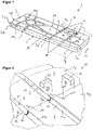
- Figure 1 shows a schematic, perspective view of a pipeline panel 1 for guiding connecting pipelines of an underfloor heating system according to an embodiment of the invention.
- the pipeline panel 1 has a laying plate 2 which is made of two layers 2a and 2b, the upper layer 2a and the lower layer 2b being made of different insulating material, namely expanded polystyrene material.
- the upper layer 2a consists of EPS DEO and the lower layer 2b of EPS DES.
- the installation plate 2 is rectangular in the form of a plate and has a first end edge 3a, a second end edge 3b opposite the first end edge 3a, a third end edge 3c and a fourth end edge 3d opposite the third end edge 3c.
- the installation plate 2 also has an upper side 4 and an underside 5 opposite this.
- the pipeline panel 1 is designed to be laid on a subsurface, such as a floor such as raw concrete, and to guide connecting pipelines of an underfloor heating system.
- the laying plate 2 is designed to be self-adhesive on the underside 5, so that the laying plate 2 can be fixed quickly and easily to the ground.
- first pipe guide channels 6 are introduced, which are open to the top 4 and are designed as approximately semi-cylindrical recesses.
- the first pipe guide channels 6 extend from the first end edge 3a to the second end edge 3b.
- Connecting pipes for example plastic pipes made of cross-linked polyethylene (PEX), with a diameter of 14 or 16 mm can be inserted or pressed into the first pipe guide channels 6 without tools.
- the tubes are held in the first channels 6 in a clamping manner, for example.
- the two first pipe routing channels 6 are designed over the entire course from the first end edge 3a to the second end edge 3b that a pipe accommodated therein from a first laying plane 7, which can also be referred to as the insulation plane, into a second laying plane 8, which is called Screed level can be designated, be transferred.
- a first laying plane 7 coincides with the parting plane of the layers 2a and 2b, but this does not necessarily have to be the case.
- the second laying plane 8 coincides with the upper side 4 of the laying plate 2.
- the first pipe guide channels 6 thus have a gradient 11 over the entire course, starting from a section start 9 to a section end 10, which is constant and continuous.
- the slope 11 can also be formed only in a section of the course of the first pipe guide channels 6.
- a sealing element 12 in the form of a U-shaped sealing lip is also introduced into each of the first pipe guide channels 6.
- These sealing elements 12 are not an obstacle to the reception of connecting pipelines.
- the sealing elements 12 are arranged in the region of the respective section start 9.
- the sealing elements 12 are arranged between the first pipe routing channel 6 and the connecting pipe line and seal the first pipe routing channels 6 in a direction 13 opposite one another a fluid, in particular screed and / or screed water.
- This seal is helpful, for example, since the first pipe guide channels 6 are inclined and thus any fluid can penetrate into further panels or carrier plates for pipes adjoining the pipe guide panel 1.
- the installation plate 2 itself is impermeable to fluid, in particular waterproof due to the material. Additionally or alternatively, the laying plate 2 has one or more water-repellent layers.
- Two second pipe guide channels 14 are also introduced into the laying plate 2, which run from the third end edge 3c to both the first and the second and fourth end edges 3a, 3b, 3d.
- the second pipe guide channels 14 each have a first, rectilinear section 14a which extends from the third front edge 3c to the fourth front edge 3d. From these first sections 14a, second sections 14b each branch off in an arc-shaped or curved manner to the first end edge 3a and in each case third sections 14c in an arc-shaped or curved manner to the second end edge 3b.
- the second pipe guide channels 14 are designed analogously to the first channels 6 for receiving connecting pipe lines, with the difference that these do not have any change in height, for example a slope. They thus run parallel to the upper side 3.
- the second channels 14 are designed in such a way that the tubes received lie in the first laying plane 7. Furthermore, a laying distance of the second channels 14 at least in the first sections 14a in the first laying plane 7 corresponds to the laying distance of the first
- the pipeline panel 1 is a modular, multifunctional panel which is suitable for the functions mentioned at the beginning.
- the pipeline panel 1 shown can also have more than the first and second pipe guide channels 6 and 14 shown.
- the pipeline panel 1 can be provided with predetermined breaking points or predetermined separation points so that, for example, only the first pipe guide channels 6 and the straight first sections 14a are present.
- a plurality of the pipeline panels 1 shown can also be designed in one piece next to one another as an entire pipeline panel with a single installation plate. In turn, predetermined breaking points or separation points can be provided in order to then obtain individual pipeline panels 1 shown.
- FIG 2 two of the pipeline panels 1 described are shown in an exemplary floor structure 30 (first panel 1a and second panel 1b). These are arranged next to one another in such a way that the second pipe guide channels 14 of the second panel 1b with the straight sections 14a merge seamlessly into the first pipe guide channels 6 of the first panel 1a.
- the panels 1a and 1b are therefore aligned rotated by 90 ° to each other.
- connecting pipes can be laid in the first laying level 7 and optionally raised to the higher level of the second laying level 8.
- the pipeline panels 1 described have the panels 1a, 1b according to Figure 2 Holding slots 15 for receiving holding elements 16, which in the example are designed as holding brackets or clips.
- retaining slots 15 are arranged in the area of the sealing elements 12 in such a way that a received connecting pipe in the corresponding pipe guide channel is clamped against the sealing element 12 by the fixing by means of retaining elements. This ensures the sealing effect or improves it.
- FIG Figure 3 shows schematically a floor plan 17 with an installation plan for a floor structure of an underfloor heating system.
- Several panels 1a and 1b are similar in structure according to FIG Figure 2 composed.
- the floor plan 17 shows a room in which, via a distributor 18, several connecting pipes 19 (shown in dashed lines, individual examples with reference numerals) are routed in pairs in the floor to different rooms 20a to 20h in order to form heating circuits H1 to H12 for underfloor heating in these rooms.
- a distributor 18 From the distributor 18, on which all of the connecting pipelines 19 are led close to one another out of the wall or a bare floor, all of the connecting pipelines 19 are routed via distributor plates 21 in the direction of the rooms 20.
- the distributor plates 21 increase the spacing between the individual connecting pipes 19.
- the distributor plates 21 are insulation panels in which the pipes 19 are laid. However, the pipes 19 are not laid on the plates 19. In other words, the pipes 19 are laid in an insulation plane which corresponds to the first laying plane 7 as described above.
- a plurality of pipeline panels 1b (some of them with reference numerals as an example) adjoin the distributor plates 21 as described above, the connecting pipes 19 being guided to the spaces 20 by means of the second pipe guide channels 14 (see above).
- a cover can be applied over the distributor plates 21 and the pipe panels 1b in the second laying level, the screed level, which in turn requires the installation of a separate, controllable heating circuit, for example according to EnEV 2014.
- pipe support plates for fastening heating pipes for screed constructions which are provided or covered with a Velcro layer or a Velcro fleece, can be brought onto the distribution plates 21 and the panels 1b.
- the insulation layer formed by the distribution plates 21 and panels 1b is not damaged in accordance with DIN18560.
- the cover prevents screed or screed water from penetrating.
- the panels 1b instead of the panels 1b, other insulation panels can also be used to distribute the connecting pipes. However, the panels 1 a are necessary to compensate for the height offset.
- pipe panels 1 are used in their other function (reference number 1a), the connecting pipes 19 being guided via the first pipe guide channels 6 into the second laying level, for example the screed level.
Landscapes
- Engineering & Computer Science (AREA)
- Physics & Mathematics (AREA)
- Thermal Sciences (AREA)
- Chemical & Material Sciences (AREA)
- Combustion & Propulsion (AREA)
- Mechanical Engineering (AREA)
- General Engineering & Computer Science (AREA)
- Steam Or Hot-Water Central Heating Systems (AREA)
- Floor Finish (AREA)
Claims (15)
- Ensemble de conduites (1) destiné à guider au moins une conduite de liaison d'un système de chauffage au sol, présentant
une plaque de pose (2) dans laquelle au moins un premier canal de guidage de tube (6) ouvert vers un côté supérieur (4) de la plaque de pose (2) est ménagé pour recevoir une conduite de liaison, sachant que le premier canal de guidage de tube (6) présente au moins un section de tracé avec un début de section (9) et une fin de section (10), caractérisé en ce que le premier canal de guidage de tube (6) est constitué depuis le début de section (9) jusqu'à la fin de section (10) de telle manière qu'une conduite de liaison posée dans le premier canal de guidage de tube (6) soit transférée d'un premier plan de pose (7) au début de section (9) à un deuxième plan de pose (8) à la fin de section (10) par rapport au côté supérieur (4). - Ensemble de conduites (1) selon la revendication 1, sachant que le premier plan de pose (7) présente un tracé parallèle décalé par rapport au côté supérieur (4) et le deuxième plan de pose (8) coïncide avec le côté supérieur (4) de la plaque de pose (2).
- Ensemble de conduites (1) selon la revendication 1 ou 2, sachant que le premier canal de guidage de tube (6) passe depuis une première arête frontale (3a) de la plaque de pose (2) en direction d'une deuxième arête frontale (3b) ou jusqu'à la deuxième arête frontale (3b) de la plaque de pose (2) .
- Ensemble de conduites (1) selon la revendication 3, sachant que la première arête frontale (3a) de la plaque de pose (2) présente le début de section (9).
- Ensemble de conduites (1) selon l'une des revendications précédentes, sachant que le premier canal de guidage de tube (6) présente un élément d'étanchéité (12), lequel est constitué de telle manière que l'élément d'étanchéité (12), dans un état dans lequel une conduite de liaison est reçue dans le premier canal de guidage de tube (6), soit disposé entre la conduite de liaison reçue et le premier canal de guidage de tube (6) et étanchéifie, conjointement avec la conduite de liaison reçue, le premier canal de guidage de tube (6) par rapport à un fluide dans une direction de passage.
- Ensemble de conduites (1) selon la revendication 5, sachant que, dans la zone de l'élément d'étanchéité (12), une ou plusieurs fentes (15) ou ouvertures de maintien sont ménagées, dans lesquelles un élément de maintien (16) peut être inséré et maintenir une conduite de liaison reçue dans le premier canal de guidage de tube (6) en la calant contre l'élément d'étanchéité (12).
- Ensemble de conduites (1) selon l'une des revendications précédentes, sachant que la plaque de pose (2) est fabriquée dans un matériau isolant.
- Ensemble de conduites (1) selon la revendication 7, sachant que la plaque de pose (2) est constituée d'au moins deux couches (2a, 2b) superposées, sachant que les couches (2a, 2b) présentent un matériau isolant respectivement différent.
- Ensemble de conduites (1) selon l'une des revendications précédentes, sachant que la plaque de pose (2) est constituée de manière autocollante sur un côté inférieur (5) opposé au côté supérieur (4).
- Ensemble de conduites (1) selon l'une des revendications précédentes, sachant que la plaque de pose (2) est constituée de manière étanche aux fluides.
- Ensemble de conduites (1) selon l'une des revendications précédentes, sachant qu'au moins un deuxième canal de guidage de tube (14) ouvert vers le côté supérieur (4) et sensiblement parallèle au côté supérieur (4) est ménagé dans la plaque de pose (2) pour recevoir une conduite de liaison.
- Ensemble de conduites (1) selon la revendication 11, sachant que le deuxième canal de guidage de tube (14) passe d'une troisième arête frontale (3c) de la plaque de pose (2) à la première arête frontale (3a), la deuxième arête frontale (3b) et/ou une quatrième arête frontale (3d) de la plaque de pose (2).
- Ensemble de conduites (1) selon l'une des revendications précédentes, sachant que le ou les canaux de guidage de tube (6, 14) sont constitués pour recevoir des tubes composites multicouche ou des tubes en matière plastique d'un diamètre de 14 mm ou de 16 mm.
- Structure de sol (30) pour un chauffage au sol, présentant un premier ensemble de conduites (1a) et un deuxième ensemble de conduites (1b) respectivement selon l'une des revendications 11 à 13 ainsi qu'au moins une conduite de liaison pour un agent de régulation de température fluide, sachant que le premier ensemble de conduites et le deuxième ensemble de conduites sont disposés l'un auprès l'autre de telle manière que- le deuxième canal de guidage de tube (14) du premier ensemble de conduites (1a) se prolonge sans soudure par le premier canal de guidage de tube (6) du deuxième ensemble de conduites (1b), et- la conduite de liaison soit reçue dans le deuxième canal de guidage de tube (14) du premier ensemble de conduites (1a) et dans le premier canal de guidage de tube (6) du deuxième ensemble de conduites (1b) de telle sorte que la conduite de liaison dans le premier ensemble de conduites (1a) passe dans un premier plan de pose (7) et soit transférée du premier plan de pose (7) à un deuxième plan de pose (8) moyennant le deuxième ensemble de conduites (1b).
- Structure de sol (30) selon la revendication 14, sachant que la conduite de liaison est fixée au deuxième ensemble de conduites (1b) via au moins un élément de maintien (16), lequel est disposé au niveau d'un élément d'étanchéité (12) disposé dans le premier canal de guidage de tube (6) de telle manière que la conduite de liaison reçue dans le premier canal de guidage de tube (6) du deuxième ensemble de conduites (1b) soit maintenue en étant calée contre l'élément d'étanchéité (12).
Applications Claiming Priority (1)
| Application Number | Priority Date | Filing Date | Title |
|---|---|---|---|
| DE202017102504.7U DE202017102504U1 (de) | 2017-04-27 | 2017-04-27 | Rohrleitungspanel und Fußbodenaufbau |
Publications (2)
| Publication Number | Publication Date |
|---|---|
| EP3396257A1 EP3396257A1 (fr) | 2018-10-31 |
| EP3396257B1 true EP3396257B1 (fr) | 2020-10-28 |
Family
ID=59119108
Family Applications (1)
| Application Number | Title | Priority Date | Filing Date |
|---|---|---|---|
| EP18167783.2A Active EP3396257B1 (fr) | 2017-04-27 | 2018-04-17 | Ensemble de conduites et structure de plancher |
Country Status (2)
| Country | Link |
|---|---|
| EP (1) | EP3396257B1 (fr) |
| DE (1) | DE202017102504U1 (fr) |
Families Citing this family (2)
| Publication number | Priority date | Publication date | Assignee | Title |
|---|---|---|---|---|
| IT202300004086A1 (it) * | 2023-03-06 | 2024-09-06 | Ecobel Srl | Pannello composito prefabbricato per sistemi radianti |
| EP4575326A1 (fr) * | 2023-12-22 | 2025-06-25 | Uponor Innovation AB | Système de chauffage par le sol, bande d'isolation et procédé de fabrication d'un système de chauffage par le sol |
Family Cites Families (4)
| Publication number | Priority date | Publication date | Assignee | Title |
|---|---|---|---|---|
| EP2052189A1 (fr) * | 2006-08-16 | 2009-04-29 | KANG, Chang-Hee | Panneau chauffant / réfrigérant |
| US9683756B2 (en) * | 2011-05-26 | 2017-06-20 | THERMA-HEXX, Corporation | Modular, fluid thermal transfer device |
| EP3112549A1 (fr) * | 2015-07-01 | 2017-01-04 | KEOKI Company SA | Panneau de construction destiné à la réalisation de parois chauffantes et/ou refroidissantes de bâtiments |
| DE202016002037U1 (de) * | 2016-04-04 | 2016-04-24 | Kermi Gmbh | System zur Flächentemperierung in Bereichen mit durchlaufenden Zuleitungen |
-
2017
- 2017-04-27 DE DE202017102504.7U patent/DE202017102504U1/de not_active Expired - Lifetime
-
2018
- 2018-04-17 EP EP18167783.2A patent/EP3396257B1/fr active Active
Non-Patent Citations (1)
| Title |
|---|
| None * |
Also Published As
| Publication number | Publication date |
|---|---|
| EP3396257A1 (fr) | 2018-10-31 |
| DE202017102504U1 (de) | 2017-06-01 |
Similar Documents
| Publication | Publication Date | Title |
|---|---|---|
| DE202016002037U1 (de) | System zur Flächentemperierung in Bereichen mit durchlaufenden Zuleitungen | |
| EP1462727B1 (fr) | Dispositif pour la pose de tubes traversés par des fluides réfrigérants ou chauffants d'un système de conditionnement thermique à grande surface | |
| EP3396257B1 (fr) | Ensemble de conduites et structure de plancher | |
| DE3135821A1 (de) | Fussbodenbelag mit integrierter warmwasser-fussbodenheizung | |
| AT14858U1 (de) | Modulares Bodenbelagselement und Bodenheizungssystem, dass aus mehreren solcher Elemente gebildet ist | |
| DE102017105557B4 (de) | Einrichtung zum Temperieren von Räumen | |
| EP0023043B1 (fr) | Chauffage de surface | |
| CH617999A5 (en) | Plate-shaped structural element for radiant heating systems | |
| DE202009000976U1 (de) | Mehrschichtige Platte und Wärmeleitplatte | |
| DE102017129823B4 (de) | System und Verfahren zur Installation einer Fußbodenheizung in einem Transferraum | |
| EP3001110B1 (fr) | Systeme de chauffage surfacique | |
| EP4134594B1 (fr) | Système électrique de mise en température de surface | |
| EP3892794A1 (fr) | Système de revêtement pour un plancher, un mur et/ou un plafond | |
| EP3181773B1 (fr) | Maconnerie pour production d'énergie | |
| DE102015102237B3 (de) | Deckenklimatisierungseinrichtung | |
| EP4689498A1 (fr) | Élément pour la formation d'un mur ou d'un toit d'un bâtiment | |
| EP3168542B1 (fr) | Système destiné à tempérer des surfaces, système d'échangeur de chaleur, procédé et procédé de montage | |
| WO2007042331A1 (fr) | Plaque d'echangeur thermique | |
| DE202020000242U1 (de) | Plattenförmige Verlegevorrichtung sowie System und Anordnung mit mehreren dieser Verlegevorrichtungen | |
| EP3324128B1 (fr) | Dispositif et méthode pour tempérer des planchers ou des murs dans des bâtiments en diminuant la génération de chaleur indésirable dans la zone des tubes de liaison et montage | |
| AT8931U1 (de) | Bodenaufbau mit auf stützen verlegten platten | |
| DE102020000361B4 (de) | Plattenförmige Verlegevorrichtung sowie System und Anordnung mit mehreren dieser Verlegevorrichtungen | |
| DE102014117729A1 (de) | Anordnung von Wärmedämmmodulen | |
| WO2018091346A1 (fr) | Système servant à l'installation d'un chauffage de surface | |
| DE202015105173U1 (de) | Auflageelement für flexible bandförmige Heizelemente einer Flächenheizung |
Legal Events
| Date | Code | Title | Description |
|---|---|---|---|
| PUAI | Public reference made under article 153(3) epc to a published international application that has entered the european phase |
Free format text: ORIGINAL CODE: 0009012 |
|
| STAA | Information on the status of an ep patent application or granted ep patent |
Free format text: STATUS: THE APPLICATION HAS BEEN PUBLISHED |
|
| AK | Designated contracting states |
Kind code of ref document: A1 Designated state(s): AL AT BE BG CH CY CZ DE DK EE ES FI FR GB GR HR HU IE IS IT LI LT LU LV MC MK MT NL NO PL PT RO RS SE SI SK SM TR |
|
| AX | Request for extension of the european patent |
Extension state: BA ME |
|
| STAA | Information on the status of an ep patent application or granted ep patent |
Free format text: STATUS: REQUEST FOR EXAMINATION WAS MADE |
|
| 17P | Request for examination filed |
Effective date: 20190417 |
|
| RBV | Designated contracting states (corrected) |
Designated state(s): AL AT BE BG CH CY CZ DE DK EE ES FI FR GB GR HR HU IE IS IT LI LT LU LV MC MK MT NL NO PL PT RO RS SE SI SK SM TR |
|
| GRAP | Despatch of communication of intention to grant a patent |
Free format text: ORIGINAL CODE: EPIDOSNIGR1 |
|
| STAA | Information on the status of an ep patent application or granted ep patent |
Free format text: STATUS: GRANT OF PATENT IS INTENDED |
|
| INTG | Intention to grant announced |
Effective date: 20200519 |
|
| GRAS | Grant fee paid |
Free format text: ORIGINAL CODE: EPIDOSNIGR3 |
|
| GRAA | (expected) grant |
Free format text: ORIGINAL CODE: 0009210 |
|
| STAA | Information on the status of an ep patent application or granted ep patent |
Free format text: STATUS: THE PATENT HAS BEEN GRANTED |
|
| AK | Designated contracting states |
Kind code of ref document: B1 Designated state(s): AL AT BE BG CH CY CZ DE DK EE ES FI FR GB GR HR HU IE IS IT LI LT LU LV MC MK MT NL NO PL PT RO RS SE SI SK SM TR |
|
| REG | Reference to a national code |
Ref country code: GB Ref legal event code: FG4D Free format text: NOT ENGLISH |
|
| REG | Reference to a national code |
Ref country code: CH Ref legal event code: EP |
|
| REG | Reference to a national code |
Ref country code: AT Ref legal event code: REF Ref document number: 1328605 Country of ref document: AT Kind code of ref document: T Effective date: 20201115 |
|
| REG | Reference to a national code |
Ref country code: DE Ref legal event code: R096 Ref document number: 502018002830 Country of ref document: DE |
|
| REG | Reference to a national code |
Ref country code: IE Ref legal event code: FG4D Free format text: LANGUAGE OF EP DOCUMENT: GERMAN |
|
| REG | Reference to a national code |
Ref country code: NL Ref legal event code: FP |
|
| PG25 | Lapsed in a contracting state [announced via postgrant information from national office to epo] |
Ref country code: FI Free format text: LAPSE BECAUSE OF FAILURE TO SUBMIT A TRANSLATION OF THE DESCRIPTION OR TO PAY THE FEE WITHIN THE PRESCRIBED TIME-LIMIT Effective date: 20201028 Ref country code: PT Free format text: LAPSE BECAUSE OF FAILURE TO SUBMIT A TRANSLATION OF THE DESCRIPTION OR TO PAY THE FEE WITHIN THE PRESCRIBED TIME-LIMIT Effective date: 20210301 Ref country code: RS Free format text: LAPSE BECAUSE OF FAILURE TO SUBMIT A TRANSLATION OF THE DESCRIPTION OR TO PAY THE FEE WITHIN THE PRESCRIBED TIME-LIMIT Effective date: 20201028 Ref country code: NO Free format text: LAPSE BECAUSE OF FAILURE TO SUBMIT A TRANSLATION OF THE DESCRIPTION OR TO PAY THE FEE WITHIN THE PRESCRIBED TIME-LIMIT Effective date: 20210128 Ref country code: GR Free format text: LAPSE BECAUSE OF FAILURE TO SUBMIT A TRANSLATION OF THE DESCRIPTION OR TO PAY THE FEE WITHIN THE PRESCRIBED TIME-LIMIT Effective date: 20210129 |
|
| REG | Reference to a national code |
Ref country code: LT Ref legal event code: MG4D |
|
| PG25 | Lapsed in a contracting state [announced via postgrant information from national office to epo] |
Ref country code: SE Free format text: LAPSE BECAUSE OF FAILURE TO SUBMIT A TRANSLATION OF THE DESCRIPTION OR TO PAY THE FEE WITHIN THE PRESCRIBED TIME-LIMIT Effective date: 20201028 Ref country code: IS Free format text: LAPSE BECAUSE OF FAILURE TO SUBMIT A TRANSLATION OF THE DESCRIPTION OR TO PAY THE FEE WITHIN THE PRESCRIBED TIME-LIMIT Effective date: 20210228 Ref country code: LV Free format text: LAPSE BECAUSE OF FAILURE TO SUBMIT A TRANSLATION OF THE DESCRIPTION OR TO PAY THE FEE WITHIN THE PRESCRIBED TIME-LIMIT Effective date: 20201028 Ref country code: PL Free format text: LAPSE BECAUSE OF FAILURE TO SUBMIT A TRANSLATION OF THE DESCRIPTION OR TO PAY THE FEE WITHIN THE PRESCRIBED TIME-LIMIT Effective date: 20201028 Ref country code: BG Free format text: LAPSE BECAUSE OF FAILURE TO SUBMIT A TRANSLATION OF THE DESCRIPTION OR TO PAY THE FEE WITHIN THE PRESCRIBED TIME-LIMIT Effective date: 20210128 Ref country code: ES Free format text: LAPSE BECAUSE OF FAILURE TO SUBMIT A TRANSLATION OF THE DESCRIPTION OR TO PAY THE FEE WITHIN THE PRESCRIBED TIME-LIMIT Effective date: 20201028 |
|
| PG25 | Lapsed in a contracting state [announced via postgrant information from national office to epo] |
Ref country code: HR Free format text: LAPSE BECAUSE OF FAILURE TO SUBMIT A TRANSLATION OF THE DESCRIPTION OR TO PAY THE FEE WITHIN THE PRESCRIBED TIME-LIMIT Effective date: 20201028 |
|
| REG | Reference to a national code |
Ref country code: DE Ref legal event code: R097 Ref document number: 502018002830 Country of ref document: DE |
|
| PG25 | Lapsed in a contracting state [announced via postgrant information from national office to epo] |
Ref country code: SM Free format text: LAPSE BECAUSE OF FAILURE TO SUBMIT A TRANSLATION OF THE DESCRIPTION OR TO PAY THE FEE WITHIN THE PRESCRIBED TIME-LIMIT Effective date: 20201028 Ref country code: EE Free format text: LAPSE BECAUSE OF FAILURE TO SUBMIT A TRANSLATION OF THE DESCRIPTION OR TO PAY THE FEE WITHIN THE PRESCRIBED TIME-LIMIT Effective date: 20201028 Ref country code: CZ Free format text: LAPSE BECAUSE OF FAILURE TO SUBMIT A TRANSLATION OF THE DESCRIPTION OR TO PAY THE FEE WITHIN THE PRESCRIBED TIME-LIMIT Effective date: 20201028 Ref country code: LT Free format text: LAPSE BECAUSE OF FAILURE TO SUBMIT A TRANSLATION OF THE DESCRIPTION OR TO PAY THE FEE WITHIN THE PRESCRIBED TIME-LIMIT Effective date: 20201028 Ref country code: SK Free format text: LAPSE BECAUSE OF FAILURE TO SUBMIT A TRANSLATION OF THE DESCRIPTION OR TO PAY THE FEE WITHIN THE PRESCRIBED TIME-LIMIT Effective date: 20201028 Ref country code: RO Free format text: LAPSE BECAUSE OF FAILURE TO SUBMIT A TRANSLATION OF THE DESCRIPTION OR TO PAY THE FEE WITHIN THE PRESCRIBED TIME-LIMIT Effective date: 20201028 |
|
| PG25 | Lapsed in a contracting state [announced via postgrant information from national office to epo] |
Ref country code: DK Free format text: LAPSE BECAUSE OF FAILURE TO SUBMIT A TRANSLATION OF THE DESCRIPTION OR TO PAY THE FEE WITHIN THE PRESCRIBED TIME-LIMIT Effective date: 20201028 |
|
| PLBE | No opposition filed within time limit |
Free format text: ORIGINAL CODE: 0009261 |
|
| STAA | Information on the status of an ep patent application or granted ep patent |
Free format text: STATUS: NO OPPOSITION FILED WITHIN TIME LIMIT |
|
| 26N | No opposition filed |
Effective date: 20210729 |
|
| PG25 | Lapsed in a contracting state [announced via postgrant information from national office to epo] |
Ref country code: IT Free format text: LAPSE BECAUSE OF FAILURE TO SUBMIT A TRANSLATION OF THE DESCRIPTION OR TO PAY THE FEE WITHIN THE PRESCRIBED TIME-LIMIT Effective date: 20201028 Ref country code: AL Free format text: LAPSE BECAUSE OF FAILURE TO SUBMIT A TRANSLATION OF THE DESCRIPTION OR TO PAY THE FEE WITHIN THE PRESCRIBED TIME-LIMIT Effective date: 20201028 |
|
| PG25 | Lapsed in a contracting state [announced via postgrant information from national office to epo] |
Ref country code: MC Free format text: LAPSE BECAUSE OF FAILURE TO SUBMIT A TRANSLATION OF THE DESCRIPTION OR TO PAY THE FEE WITHIN THE PRESCRIBED TIME-LIMIT Effective date: 20201028 Ref country code: SI Free format text: LAPSE BECAUSE OF FAILURE TO SUBMIT A TRANSLATION OF THE DESCRIPTION OR TO PAY THE FEE WITHIN THE PRESCRIBED TIME-LIMIT Effective date: 20201028 |
|
| PG25 | Lapsed in a contracting state [announced via postgrant information from national office to epo] |
Ref country code: LU Free format text: LAPSE BECAUSE OF NON-PAYMENT OF DUE FEES Effective date: 20210417 |
|
| REG | Reference to a national code |
Ref country code: BE Ref legal event code: MM Effective date: 20210430 |
|
| PG25 | Lapsed in a contracting state [announced via postgrant information from national office to epo] |
Ref country code: CH Free format text: LAPSE BECAUSE OF NON-PAYMENT OF DUE FEES Effective date: 20210430 Ref country code: LI Free format text: LAPSE BECAUSE OF NON-PAYMENT OF DUE FEES Effective date: 20210430 |
|
| PG25 | Lapsed in a contracting state [announced via postgrant information from national office to epo] |
Ref country code: IE Free format text: LAPSE BECAUSE OF NON-PAYMENT OF DUE FEES Effective date: 20210417 |
|
| PG25 | Lapsed in a contracting state [announced via postgrant information from national office to epo] |
Ref country code: IS Free format text: LAPSE BECAUSE OF FAILURE TO SUBMIT A TRANSLATION OF THE DESCRIPTION OR TO PAY THE FEE WITHIN THE PRESCRIBED TIME-LIMIT Effective date: 20210228 |
|
| PG25 | Lapsed in a contracting state [announced via postgrant information from national office to epo] |
Ref country code: BE Free format text: LAPSE BECAUSE OF NON-PAYMENT OF DUE FEES Effective date: 20210430 |
|
| PG25 | Lapsed in a contracting state [announced via postgrant information from national office to epo] |
Ref country code: CY Free format text: LAPSE BECAUSE OF FAILURE TO SUBMIT A TRANSLATION OF THE DESCRIPTION OR TO PAY THE FEE WITHIN THE PRESCRIBED TIME-LIMIT Effective date: 20201028 |
|
| PG25 | Lapsed in a contracting state [announced via postgrant information from national office to epo] |
Ref country code: HU Free format text: LAPSE BECAUSE OF FAILURE TO SUBMIT A TRANSLATION OF THE DESCRIPTION OR TO PAY THE FEE WITHIN THE PRESCRIBED TIME-LIMIT; INVALID AB INITIO Effective date: 20180417 |
|
| PG25 | Lapsed in a contracting state [announced via postgrant information from national office to epo] |
Ref country code: MK Free format text: LAPSE BECAUSE OF FAILURE TO SUBMIT A TRANSLATION OF THE DESCRIPTION OR TO PAY THE FEE WITHIN THE PRESCRIBED TIME-LIMIT Effective date: 20201028 |
|
| REG | Reference to a national code |
Ref country code: AT Ref legal event code: MM01 Ref document number: 1328605 Country of ref document: AT Kind code of ref document: T Effective date: 20230417 |
|
| PG25 | Lapsed in a contracting state [announced via postgrant information from national office to epo] |
Ref country code: TR Free format text: LAPSE BECAUSE OF FAILURE TO SUBMIT A TRANSLATION OF THE DESCRIPTION OR TO PAY THE FEE WITHIN THE PRESCRIBED TIME-LIMIT Effective date: 20201028 |
|
| PG25 | Lapsed in a contracting state [announced via postgrant information from national office to epo] |
Ref country code: AT Free format text: LAPSE BECAUSE OF NON-PAYMENT OF DUE FEES Effective date: 20230417 |
|
| PG25 | Lapsed in a contracting state [announced via postgrant information from national office to epo] |
Ref country code: AT Free format text: LAPSE BECAUSE OF NON-PAYMENT OF DUE FEES Effective date: 20230417 |
|
| PG25 | Lapsed in a contracting state [announced via postgrant information from national office to epo] |
Ref country code: MT Free format text: LAPSE BECAUSE OF FAILURE TO SUBMIT A TRANSLATION OF THE DESCRIPTION OR TO PAY THE FEE WITHIN THE PRESCRIBED TIME-LIMIT Effective date: 20201028 |
|
| PGFP | Annual fee paid to national office [announced via postgrant information from national office to epo] |
Ref country code: NL Payment date: 20250418 Year of fee payment: 8 |
|
| PGFP | Annual fee paid to national office [announced via postgrant information from national office to epo] |
Ref country code: DE Payment date: 20250422 Year of fee payment: 8 |
|
| PGFP | Annual fee paid to national office [announced via postgrant information from national office to epo] |
Ref country code: GB Payment date: 20250423 Year of fee payment: 8 |
|
| PGFP | Annual fee paid to national office [announced via postgrant information from national office to epo] |
Ref country code: FR Payment date: 20250425 Year of fee payment: 8 |
|
| PGFP | Annual fee paid to national office [announced via postgrant information from national office to epo] |
Ref country code: AT Payment date: 20260410 Year of fee payment: 5 |